INSTRUCTION MANUAL
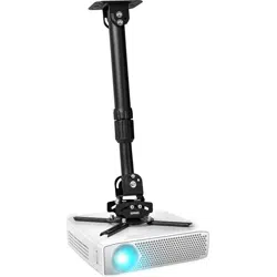
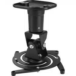
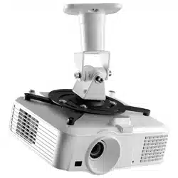
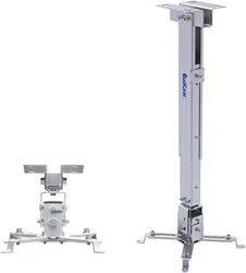
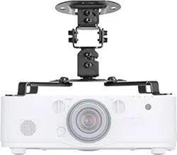
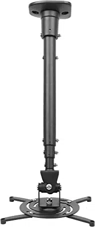
UNIVERSAL PROJECTOR MOUNT
Maximum Load: 13.6 kg (30 lbs)
Tilt Range: up to 25° up and 25° down
Swivel Range: up to 360°
Distance from Ceiling: 58.3 cm to 110.8 cm (23.0” to 43.6”)
Read these instructions before you begin. If you are unsure
of any part of the process, contact a professional contractor or
installer for assistance. Improper installation can result in injury
or damage.
The ceiling or mounting surface must be capable of
supporting the combined weight of the mount and the
projector; if not, the structure must be reinforced.
Locate pipes, wires, or any other hazards in the area where you
wish to install the mount before drilling.
Safety gear and proper tools must be used. Failure to do so
can result in injury or damage.
Follow all instructions and recommendations regarding
adequate ventilation and suitable locations for mounting your
projector. Consult the owner‘s manual for your particular
display for more information.
CAUTION: This mount is intended for use only with the
maximum weight of 13.6 kg (30 lbs). Use with heavier than the
maximum weights indicated may result in instability causing
possible injury.
1
2
3
4
(A) Wood Screw (x2)
(B) Concrete Anchor (x2)
(C) M5 x 14 Screw (x4)
(F) M4 x 40 Screw (x4)
(D) M5 Washer (x4)
(G) M6 x 16 Screw (x4)
(J) S3 Allen Key (x1)
(K) M6 x 35 Screw (x1)
5
SPECIFICATIONS
BOX CONTENTS
HARDWARE KIT
TOOLS REQUIRED
WARNINGS
(I) M4 Washer (x4)
Phillips Head Screw Driver
Electric or Portable Drill
5 mm (3/16”) Drill Bit and Stud Finder for Drywall Installation
8 mm (5/16”) Masonry Bit for Concrete Installation
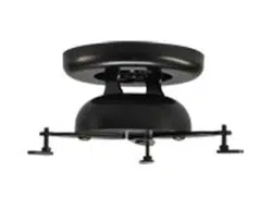
Ceiling Plate (x1)
Mount Body (x1)
Mount Hook (x1)
Mount Base (x1)
Mount Arm (x4)
Extension Pipe (x1)
Instruction Manual (x1)
Hardware Kit (x1)
(E) M4 x 16 Screw (x4)
(H) M6 x 40 Screw (x4)
(L) M6 x 40 Screw (x2)
(M) M6 x 45 Screw (x2)
(N) M6 x 56 Screw (x1)
(O) M6 Spring Washer (x6)
(P) M6 Nut (x6)
IMPORTANT! For safety reasons, the concrete ceiling must be
capable of supporting the combined weight of the mount and
the display. The manufacturer takes no responsibility for failure
caused by a ceiling of insufficient strength.
1
2
3
4
Use a high quality stud finder to locate a ceiling joist where
you wish to install your mount. Mark both edges of the joist to
help identify the exact center.
NOTE: You must use the center of the joist to avoid cracking
or splitting the wood during installation.
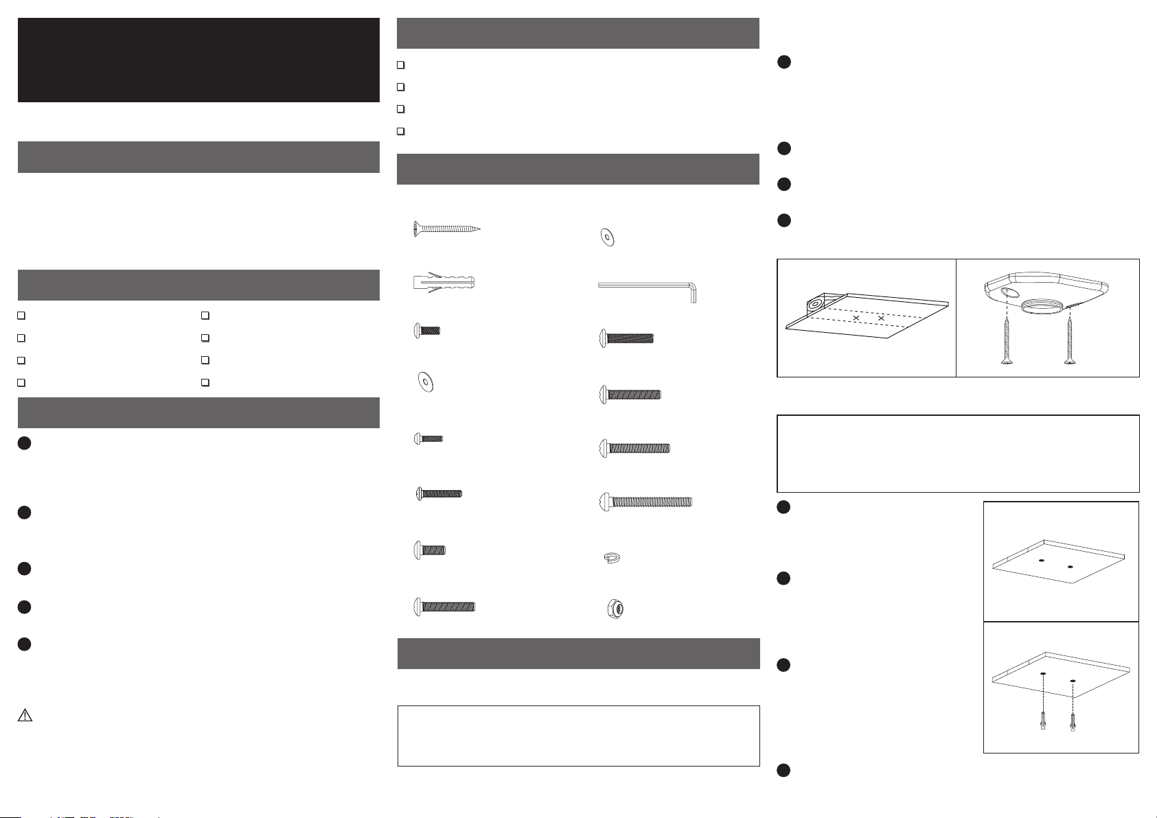
Place the ceiling plate over the joist and mark two locations
for securing the plate to the ceiling.
Set the ceiling plate aside and drill a 5 mm (3/16”) pilot hole at
each marked location (see Fig. 1).
Attach the ceiling plate to the ceiling using the wood screws
(A) provided (see Fig. 2).
1
2
3
4
IMPORTANT! For safety reasons, this mount must be secured
to a wooden ceiling joist. The joist must be capable of
supporting the combined weight of the mount and display.
Part 1A – Mounting to the Ceiling (Drywall)
Part 1A – Mounting to the Ceiling (Drywall) (continued)
INSTALLATION
Fig. 2Fig. 1
Part 1B –Mounting to the Ceiling (Concrete)
Place the ceiling plate in the
desired location and mark two
locations for securing it to the
ceiling.
Set the ceiling plate aside and
drill an 8 mm (5/16”) hole at
each marked location. Remove
any excess dust from the holes
(see Fig. 3).
Insert a concrete anchor (B) into
each hole so that it is flush with
the concrete surface (see Fig. 4).
A hammer can be used to lightly
tap the anchors into place if
necessary.
Attach the ceiling plate to the ceiling using the wood screws
(A) provided (see Fig. 2).
Fig. 3
Fig. 4
Part 3 – Assembling the Mount
0502-20121101
2
3
1
Swivel adjustment can be made by simply turning your
projector in the desired direction.
Tilt adjustments can be made by loosening the screws on
both sides of the mount base, moving the projector to the
desired angle, and then re-tightening the screws.
Height adjustments can be made by removing the screws
from the extension pipe, moving the projector to the desired
height, and replacing the screws.
OPERATION AND ADJUSTMENT
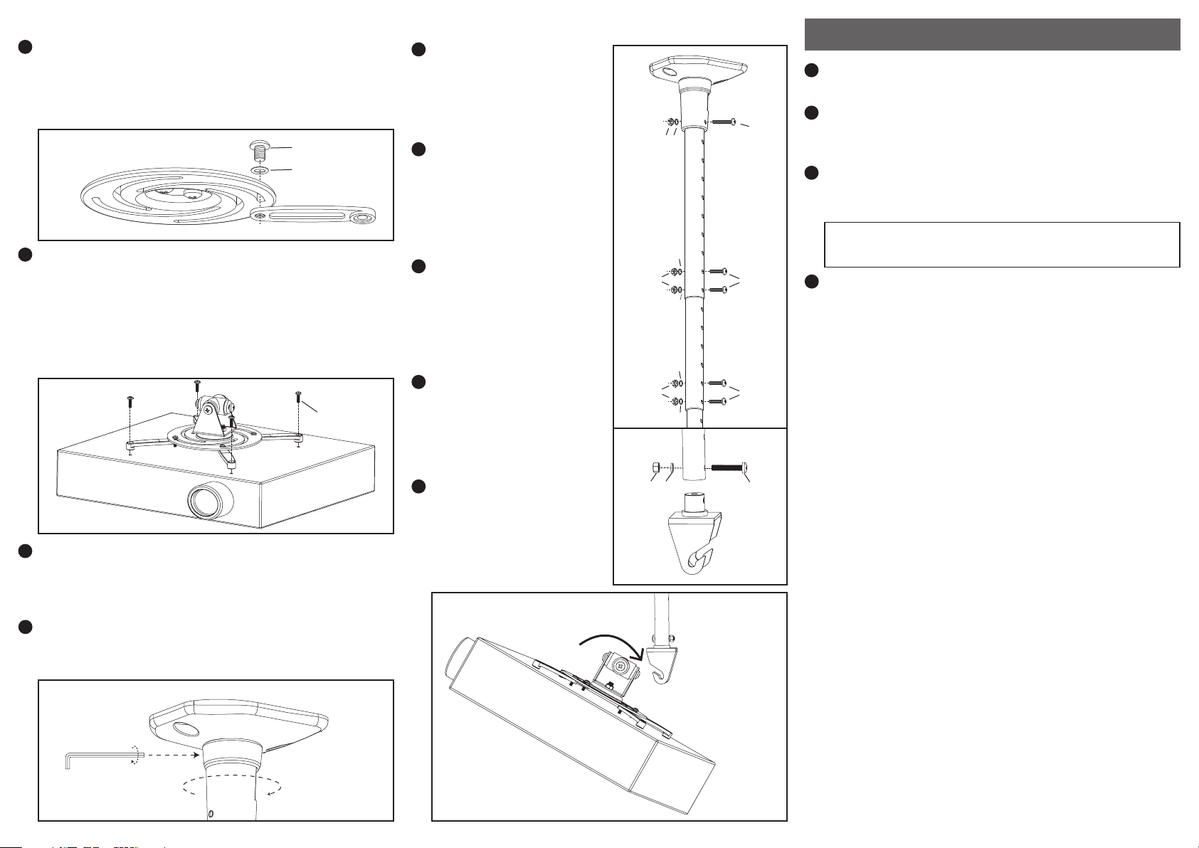
Screw the mount body into the ceiling plate as shown (see
Fig. 7). Tighten the set screw at the top of the mount body
using the S3 Allen key (J) from the hardware kit.
1
Place the mount base with
your projector attached onto
the mount hook (see Fig. 10).
Tighten the screws on the
sides of the mount base to
hold it in place.
Part 3 – Assembling the Mount (continued)
Attach the wider end of the
extension pipe to the mount
body using the M6 x 56 screw
(N) along with an M6 spring
washer (O) and M6 nut (P)
(see Fig. 8) .
Adjust the top and middle
portions of the extension pipe
and secure them using both
M6 x 45 screws (M) from the
hardware kit along with M6
spring washers (O) and M6
nuts (P) (see Fig. 8).
Adjust the middle and bottom
portions of the extension pipe
and secure them using both
M6 x 40 screws (L) from the
hardware kit along with M6
spring washers (O) and M6
nuts (P) (see Fig. 8).
Attach the mount hook to the
bottom of the extension pipe
using the M6 x 35 screw (K)
along with an M6 spring
washer (O) and M6 nut (P)
(see Fig. 9).
2
3
4
5
6
Periodically clean your mount with a dry cloth. Inspect all
screws and hardware at regular intervals to ensure that no
connections have become loose over time. Re-tighten as
needed.
4
1
Attach the mount arms to the mount base as shown using the
M5 x 14 screws (C) and M5 washers (D) from the kit (see Fig. 5).
Attach one mount arm into each slot in the mount base.
Leave the screws loose enough so that the arms can be
moved when attaching the projector.
3
Tighten the M5 x 14 screws (C) used to attach the arms to the
mount base in step 1.
2
Attach your projector to the mount arms as shown (see Fig. 6)
using the appropriate screw from the hardware kit (E, F, G, or
H). If you are using M4 screws (E or F), you will also need to use
the M4 washers (I).
NOTE: If you cannot find a screw from the provided hardware
kit that fits, consult the manufacturer of your display for the
proper size.
Fig. 5
IMPORTANT! For safety, all bolts provided in the hardware
kit must be used at all times.
Part 2 – Attaching the Projector to the Mount
Fig. 6
Fig. 9
Fig. 7
Fig. 10
N
P
O
L
O
P
O
M
O
P
O
Fig. 8
P O
K
E, F, G or H
C
D