
Owner´s Manual
Mode d´emploi
Pre-Amplifier
Préamplificateur
Français
English
2
Thank you and congratulations on your purchase of this Yamaha product.
¡
You can enjoy the high-quality stereo sound of this preamplier at home.
¡
This Owner’s Manual describes the unit’s features, connection procedures, and operations.
¡
To use the product properly and safely, we suggest that you read this manual and Safety Brochure
(separate booklet) thoroughly.
Keep the manual in a safe, accessible place for future reference.
You can download a PDF version of this manual from the following Yamaha website.
https://download.yamaha.com/
Features
¡
Left-right symmetrical design creates a bookmatched structure
¡
Class A operation of full-stage, full-oating balanced signal transmission from input to output
¡
Full-oating and balanced phono EQ amplier with balanced inputs
¡
High-accuracy controls that employ a proprietary bearing structure and high-rigidity lever switches
¡
Twin transformer designed specically for audio, which is completely separate from the control power
supply
¡
Stable mechanical grounding construction dramatically lessens the impact of external vibration.
¡
Tone control circuit that features a proprietary parallel volume system
¡
Newly-designed brass spiked feet
¡
Gain control function that enables ultra ne volume adjustment
About this manual
¡
The illustrations as shown in this manual are for instructional purposes only.
¡
The company names and product names in this manual are the trademarks or registered trademarks of
their respective companies.
¡
“
WARNING
” describes precautions to be followed to avoid the possibility of serious injury or
even death.
¡
“
CAUTION
” describes precautions to be followed to avoid the possibility of injury.
¡
“
NOTICE
” describes precautions to be followed to avoid the possibility of malfunction/damage to the
product, or damage to data.
¡
“
Note
” describes supplemental information about the product.
¡
Before starting to use the product, please be sure to read the separate “Safety Brochure”.
English

3
English
Table of contents
Features . . . . . . . . . . . . . . . . . . . . . . . . 2
About this manual . . . . . . . . . . . . . . . . .2
Supplied accessories . . . . . . . . . . . . . . . . 4
Maintenance . . . . . . . . . . . . . . . . . . . . . 4
Mirror-nish side panels . . . . . . . . . . . . .4
Surfaces other than the mirror-nish
side panels . . . . . . . . . . . . . . . . . . . . . 4
Part Names and Functions
Front panel . . . . . . . . . . . . . . . . . . . . . . 6
Rear panel. . . . . . . . . . . . . . . . . . . . . .10
Balanced and unbalanced connections . . 14
Remote control . . . . . . . . . . . . . . . . . . 16
Installing batteries in the remote control
. . 18
Operating the remote control . . . . . . . . 18
Connections
Connecting an external component . . . . . 20
Connecting a turntable . . . . . . . . . . . . 22
Connecting a recording component . . . . 22
Connecting another preamplier . . . . . . 23
Connecting a power amplier and
an active subwoofer . . . . . . . . . . . . . . 23
Trigger connections . . . . . . . . . . . . . . . 24
Controlling the power on-and-o operation
of a connected component, such as
a power amplier, in sync with this unit . . 24
Controlling the unit’s power on-and-
o operation in sync with a connected
component, such as an AV receiver. . . . .24
Remote connections . . . . . . . . . . . . . . . 25
Operating the unit from another room . . 25
Remote connection between Yamaha
components . . . . . . . . . . . . . . . . . . . 25
Connecting the power cord. . . . . . . . . . .26
Operations
Turning the power on . . . . . . . . . . . . . . 28
Selecting the input and output . . . . . . . . 28
Selecting the input from the EXT.IN jacks
. . 29
Adjusting the turntable input setting . . . . 29
PHONO selector . . . . . . . . . . . . . . . . . 29
Subsonic lter . . . . . . . . . . . . . . . . . . 30
Adjusting the volume level . . . . . . . . . . . 30
Lowering the volume level momentarily
. . 31
Adjusting the tone . . . . . . . . . . . . . . . . 31
Connecting headphones . . . . . . . . . . . . 32
Reference Materials
General specications . . . . . . . . . . . . . . 34
Block diagram . . . . . . . . . . . . . . . . . . . 36
Audio characteristics . . . . . . . . . . . . . . .37
Frequency response (tone control) . . . . . 37
Total harmonic distortion (PHONO). . . . .37
Frequency response (subsonic lter) . . . .38
Volume curve. . . . . . . . . . . . . . . . . . .38
Troubleshooting. . . . . . . . . . . . . . . . . .39
Index . . . . . . . . . . . . . . . . . . . . . . . . . 41
4
Supplied accessories
Please make sure that the following accessories are included in the package.
• Remote control
• Batteries (AAA, R03, UM-4) (x2)
• Power cord
• Owner’s Manual (this book)
• Safety Brochure (separate booklet)
WARNING
Do not use the supplied power cord for other devices.
Maintenance
To use this product for an extended period of time, we recommend that you maintain it regularly.
WARNING
• Check the power cord regularly to see if it is dusty. If so, wipe o the dust completely. Otherwise, re or electric shock might be
caused.
• Do not use aerosol or ammable gas spray for cleaning or lubrication. Otherwise, ammable gas will build up inside the unit,
causing possible explosion or re.
NOTICE
• Use a dry soft cloth to clean the unit. Using cleaning agents, such as benzene or thinner, detergent, or chemically-treated cloth
might cause color changes or deterioration of the surface. If the surface gets very dirty, damp a cloth with detergent (diluted
with water), wring the cloth tightly, and wipe o the dirt.
• If you wipe the surface area in the vicinity of the Yamaha logo with force, the logo might peel o or ber from the cloth might
stick to the surface.
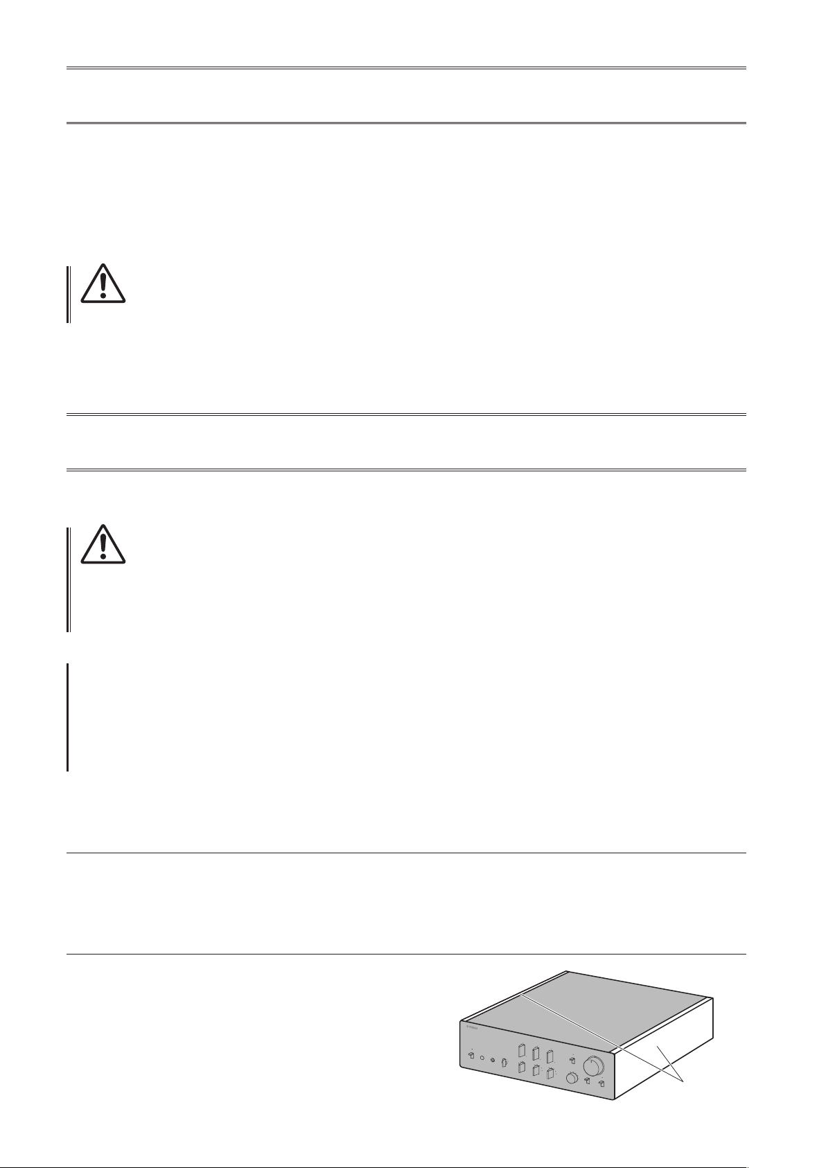
Mirror-nish side panels
We recommend that you use a cleaning cloth such as those made for pianos. If the surface is very dirty, use a soft cloth
that is damp with water and wrung tightly.
Surfaces other than the mirror-nish side panels
Wipe other surfaces using a soft dry cloth. If the surface gets
very dirty, dampen a cloth with detergent diluted in water,
wring the cloth tightly, and then wipe the dirt from the surface.
Mirror-nish
side panels

5
English
Part Names and Functions
This section lists the names and describes the function of
various parts on the front and rear panels, and the remote control.

6
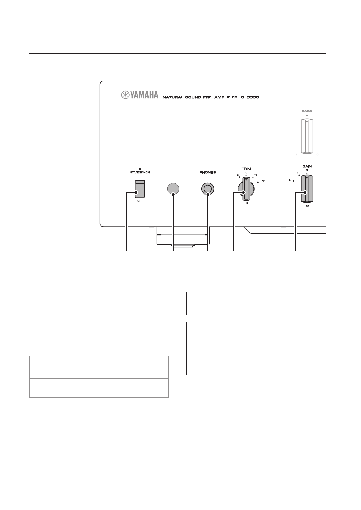
Front panel
A.
STANDBY/ON/OFF (Power)
switch/ indicator
Turns the power to the unit on (standby) or off.
STANDBY/ON
: Switches between standby and on using
the
A
AMP key on the remote control.
OFF
: Turns the power to the unit off.
Power status Indicator
On mode Lit brightly
Standby mode Lit dimly
O mode Off
The unit will enter standby mode not only when you
press the AMP key on the remote control, but also in one
of the following events:
• If the unit is powered on but not operated for eight
hours while the auto power standby function is turned
on, or
• If you turn off the power to the device that is connected
to this unit’s TRIGGER IN jack.
For more information, refer to “
Q
AUTO POWER
STANDBY switch” in the “Rear panel” section (page
13) and to “Trigger connections” (page 24).
Note
After you turn on the unit, it will take a few seconds before
the unit can reproduce sound.
NOTICE
If you plan not to use the unit for an extended period of
time, be sure to unplug the power cord from the AC outlet.
Even when the STANDBY/ON/OFF (Power) switch is turned
o (the power indicator is dark), a minimal amount of
electric current is still owing to the unit.
B.
Remote control sensor
Receives signals from the remote control. For more
information, refer to “Operating the remote control”
(page 18).
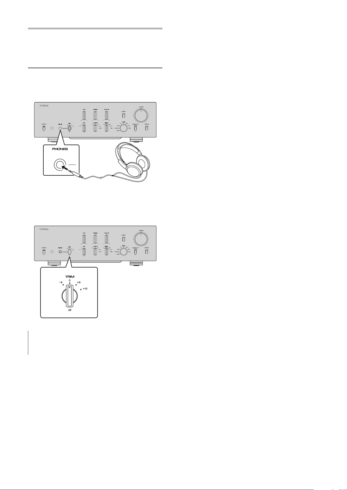
C.
PHONES jack
Connect your headphones here to listen to music
privately. For more information, refer to “Connecting
headphones” (page 32).

7
English
D.
TRIM selector
Switches the headphone amp gain. The unit will adjust
the volume level when headphones are plugged in to
avoid sudden changes in volume by modifying the level
balance between the audio output from the PHONES jack
and from the speakers.
Choices
: −6 dB, 0 dB, +6 dB, +12 dB
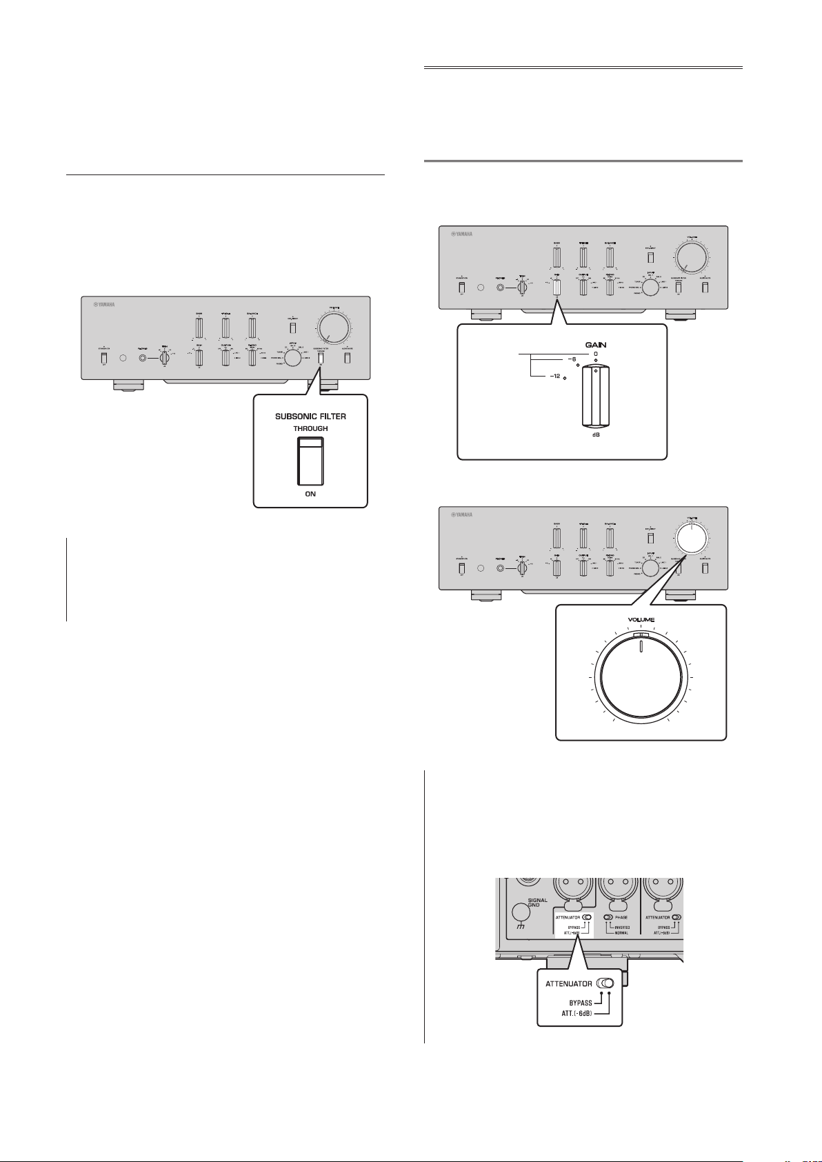
E.
GAIN selector
Switches the preamp gain. The unit will smoothly adapt to
the power amp gain and speaker sensitivity, enabling you
to make ne volume adjustments. For more information,
refer to “Adjusting the volume level” (page 30).
Choices
: −12 dB, −6 dB, 0 dB
F.
OUTPUT selector
Species which OUTPUT jacks will output signals, as
follows:
Use this selector if multiple power ampliers are
connected.
OUTPUT selector
OFF ALL BAL LINE1 LINE2
BAL
jacks
—
Output Output
— —
LINE 1
jacks
—
Output
—
Output
—
LINE 2
jacks
—
Output
— —
Output
G.
PHONO selector
Indicates the type of cartridge installed on the turntable
that is connected to the PHONO jacks on the rear panel
(
MM, MC 300, MC 100, MC 30, MC 10
). For
more information, refer to “Adjusting the turntable input
setting” (page 29).
NOTICE
Before you replace the cartridge, be sure to turn o the
power to this unit.

8
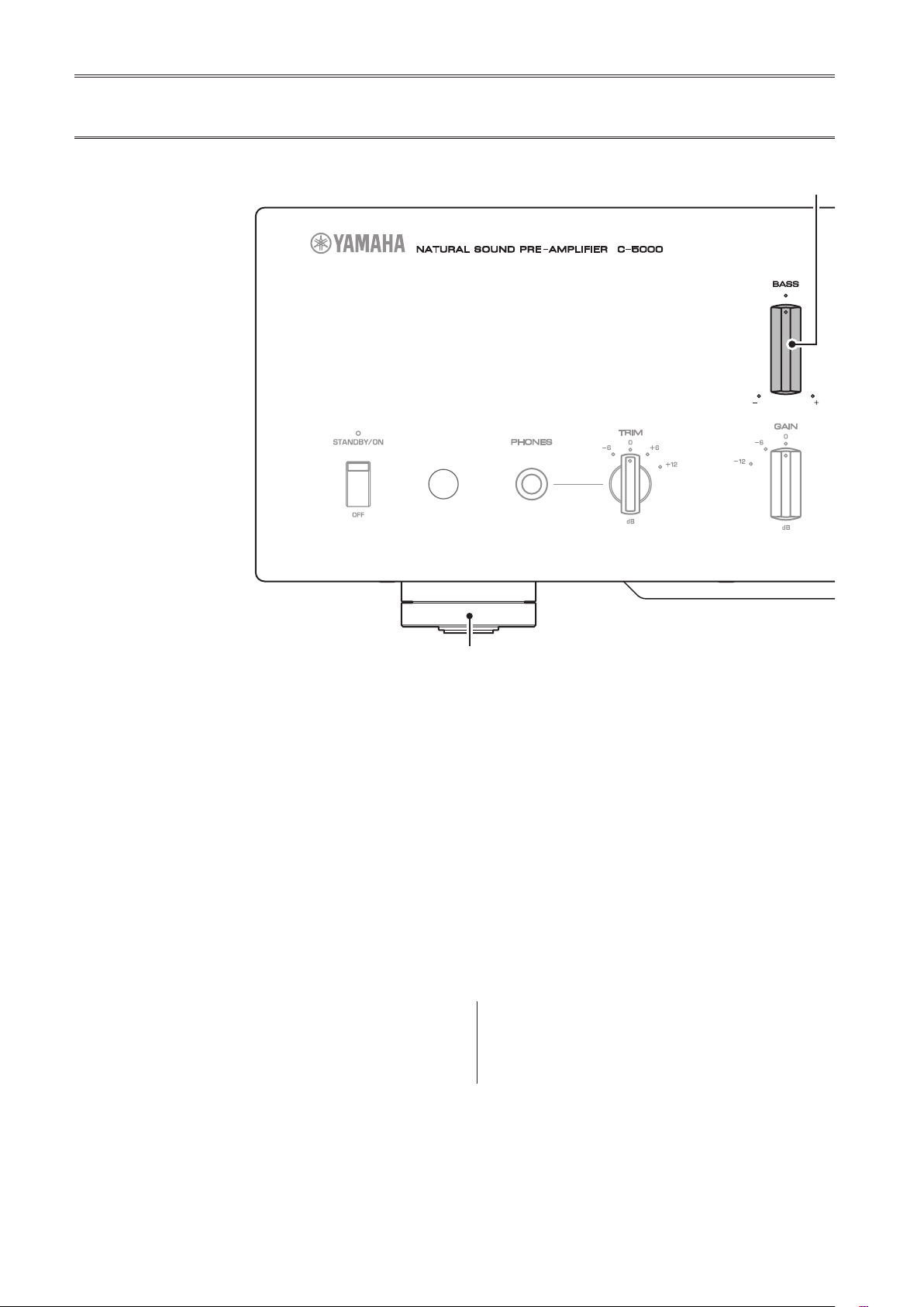
H.
BASS control
Adjusts the low-frequency response in the range from
−10 dB to +10 dB (in 0.5 dB steps). The center position
produces a at response.
I.
TREBLE control
Adjusts the high-frequency response in the range from
−10 dB to +10 dB (in 0.5 dB steps). The center position
produces a at response.
J.
BALANCE control
Adjusts the audio output balance between the left and
right speakers in the range from L (the right channel is
muted) to R (the left channel is muted) to compensate
for sound imbalances caused by speaker locations or
listening room conditions.
K.
EXT. DIRECT switch/indicator
If you press the EXT. DIRECT switch once, the EXT.
DIRECT indicator will light up, and the audio source
input at the EXT. IN jacks will be output at the connected
output jacks. For more information, refer to “Connecting
another preamplier” (page 23) and “Selecting the
input and output” (page 28).
If you press the EXT. DIRECT switch again or rotate
the INPUT selector, the signal specied by the INPUT
selector will become the input source, and the EXT.
DIRECT indicator will turn off.
Note
If EXT. DIRECT is selected, no signal will be output at the
LINE 2 OUT (recording) jacks nor at the PHONES jack.
Front panel

9
English
L.
INPUT selector/indicator
Enables you to select the input source to play back.
Options are:
PHONO, PHONO BAL, TUNER, CD, BAL 1,
BAL 2, LINE 1, and LINE 2
. The indicator for the selected
input source lights up.
Note
If LINE 2 is selected here, audio signals will not be output at
the LINE 2 OUT (recording) jacks.
M.
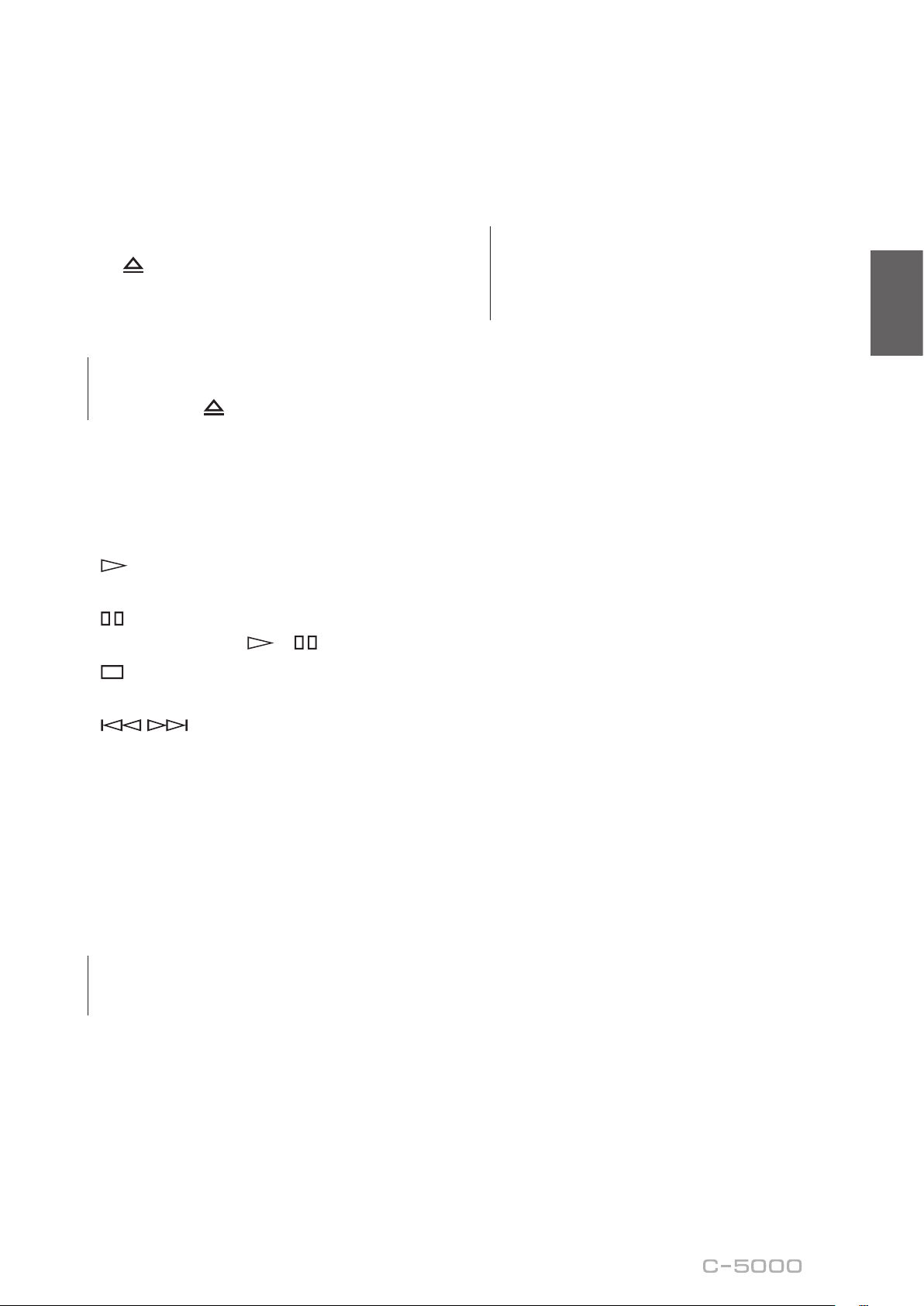
SUBSONIC FILTER switch
Toggles between
ON
(enabled) and
THROUGH
(disabled)
for the subsonic lter. For more information, refer to
“Adjusting the turntable input setting” (page 29).
Note
If the INPUT selector is set to any option other than PHONO
or PHONO BAL, the lter will be disabled.
N.
AUDIO MUTE switch/indicator
Press this switch to reduce the current volume level by
approximately 20 dB. The indicator will light up. Press
again to restore the audio output to the previous volume
level. The indicator will turn off.
O.
VOLUME control
Adjusts the volume level. This setting will not affect the
output level at the LINE 2 OUT (recording) jacks.
Note
The VOLUME control will not aect the volume level if EXT.
DIRECT is selected as the input source. To adjust the volume
level, use the volume control on the external preamplier
or another component connected to the EXT. IN jacks.
P.
Feet
If the unit is unstable, adjust the height of the feet as
needed by rotating them.

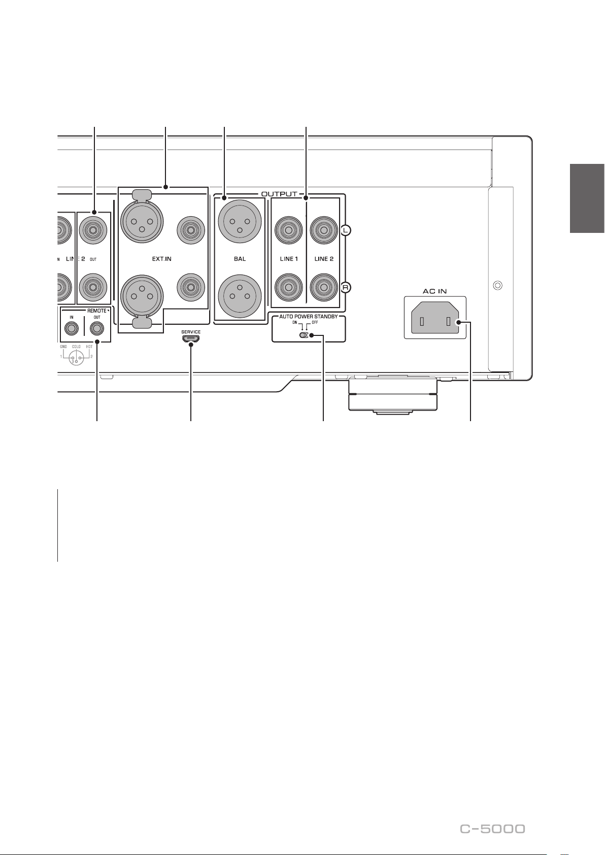
10
Note
For information regarding the connection procedure, refer
to “Connections” (page19).
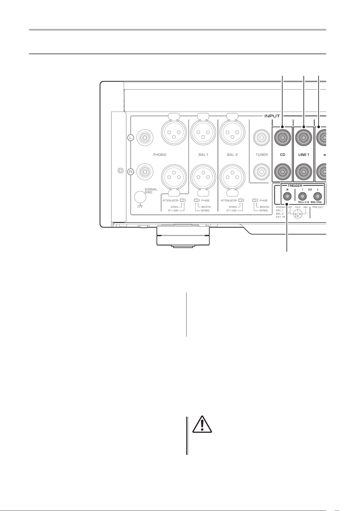
A.
PHONO jacks
RCA and XLR-type jacks. If the INPUT selector is set
to PHONO, the signals at the RCA-type PHONO jacks
will be the input source. If the INPUT selector is set to
PHONO BAL, the signals at the XLR-type PHONO jacks
will be the input source.
Your preamplier comes with a shorting plug installed on
each RCA-type PHONO input jack. If you are planning
to connect an external component to these jacks, remove
the shorting plugs. For more information, refer to
“Connecting a turntable” (page 22).
PHONO
CAUTION
Handle the shorting plugs carefully. Do not allow children
to play with the shorting plug; otherwise they might
swallow it.
NOTICE
• Shorting plugs are intended for unused INPUTS ONLY;
using them on OUTPUTS can cause serious damage to
your components.
• If you are planning not to use the RCA-type PHONO input
jacks, insert the shorting plugs into the jacks to prevent
random static or noise from degrading the audio signal.
B.
SIGNAL GND (ground) terminal
If you connect your turntable to the RCA-type PHONO
input jacks, also connect the turntable to this terminal.
Doing so may reduce noise.
Rear panel

11
English
C.
BAL 1/BAL 2 jacks
These are two sets of XLR-type balanced input jacks. If
the INPUT selector is set to BAL 1 or BAL 2, signals at
the corresponding XLR jacks will be the input source.
Note
Set the ATTENUATOR selector and PHASE selector
appropriately for the playback components that are
connected to the unit.
D.
ATTENUATOR selector
Enables you to set the allowable input level for the XLR-
type balanced input jacks (BAL 1 and BAL 2 jacks). For
more information, refer to “Adjusting the volume level”
(page 30).
BYPASS
: The allowable input level will not change.
Usually select this option.
ATT. (−6 dB)
: The input gain will be lowered by 6 dB
to raise the allowable input level. Select this option if
the audio output from the connected component sounds
distorted.
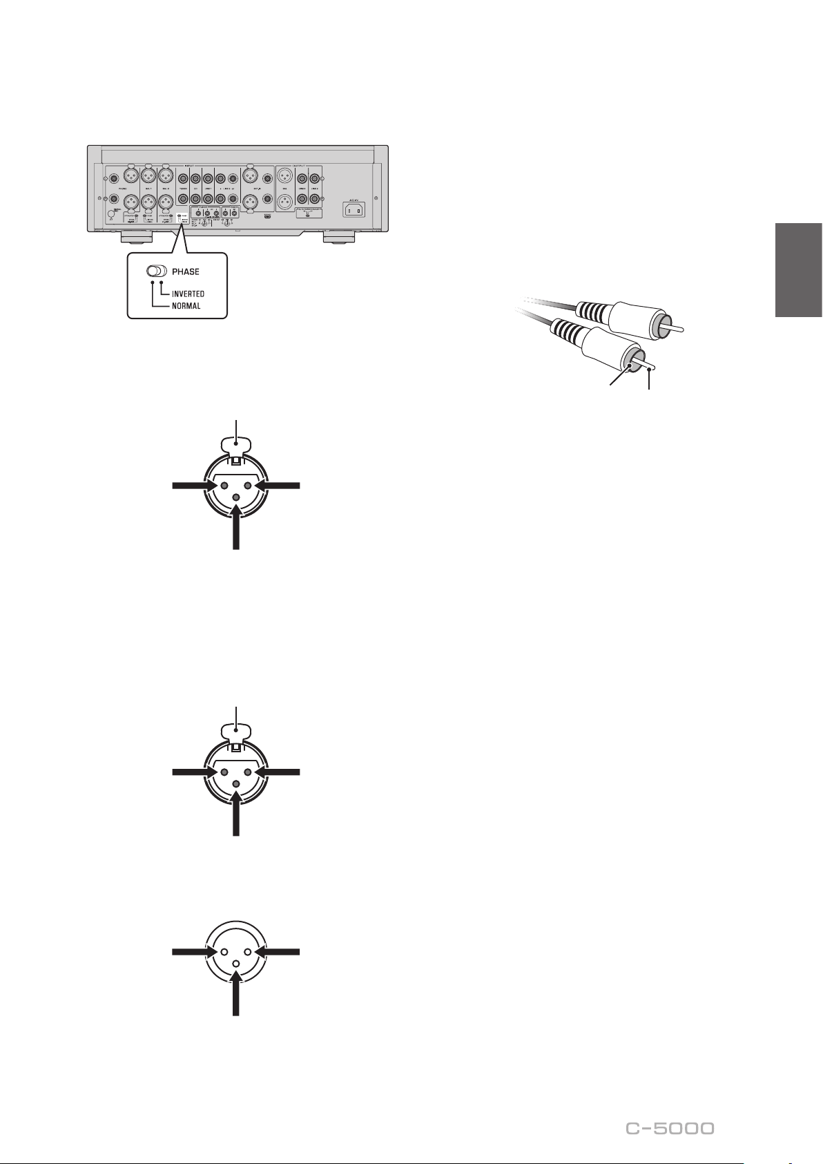
E.
PHASE selector
Species the HOT pin position for the XLR-type
balanced input jacks (BAL 1 and BAL 2 jacks).
NORMAL
: Pin #2 is specied as HOT.
INV.
: Pin #3 is specied as HOT.
For more information, refer to “Balanced and unbalanced
connections” (page 14).
F.
TUNER jacks
These are RCA input jacks. If the INPUT selector is set
to TUNER, signals at these jacks will be the input source.
Connect your tuner here.

12
G.
CD jacks
These are RCA input jacks. If the INPUT selector is set
to CD, signals at these jacks will be the input source.
Connect your CD player here.
H.
LINE 1 jacks
These are RCA input jacks. If the INPUT selector is set
to LINE 1, signals at these jacks will be the input source.
I.
LINE 2 IN jacks
These are RCA input jacks. If the INPUT selector is set
to LINE 2, these jacks will be the input source.
J.
LINE 2 OUT (recording) jacks
These are RCA input jacks for recording. These jacks
normally output the input source signals selected via the
front panel or remote control. For information on the
connection procedure, refer to “Connecting a recording
component” (page 22).
Note
• Connect the LINE 2 IN jacks and LINE 2 OUT (recording)
jacks to the same component.
• The LINE 2 OUT (recording) jacks will not output any
signals if the INPUT selector is set to LINE 2 or the EXT.
DIRECT switch is pressed.
K.
EXT.IN jacks
These jacks feature XLR-type input jacks and RCA
input jacks. If the EXT. DIRECT switch is pressed,
signals at these jacks will be the input source. Connect
your preamplier here. For more information, refer to
“Connecting another preamplier” (page 23).
CAUTION
You cannot adjust the volume level of the signals input at
the EXT. IN jacks. Therefore, be sure to connect to the EXT.
IN jacks a component that features a volume control.
Rear panel
13
English
Note
The volume level is xed. Operating the VOLUME control or
GAIN selector on this unit will not change the volume level
of the signal from the EXT. IN jacks. Adjust the volume level
using the volume control on the component connected to
the EXT. IN jacks.
L.
BAL jacks
These are XLR-type output jacks. Connect these jacks to
the balanced input jacks on the power amplier.
M.
LINE 1/LINE 2 jacks
These are RCA output jacks. Connect these jacks to the
RCA input jacks on the power amplier.
N.
TRIGGER IN/TRIGGER OUT jacks
These are monaural mini jacks. Connect external
components that support the trigger function here.
For more information, refer to “Trigger connections”
(page 24).
O.
REMOTE IN/REMOTE OUT jacks
These are monaural mini jacks. Connect external
components that support the remote function here.
For more information, refer to “Remote connections”
(page 25).
P.
SERVICE jack
This jack is used to service the product. It is rarely used.
Q.
AUTO POWER STANDBY switch
Species whether the unit automatically enters standby
mode.
ON
: The unit enters standby mode automatically if it is
powered on but not operated for eight hours.
OFF
: The unit does not enter standby mode automatically.
R.
AC IN jack
Connect the supplied power cord here. For more
information, refer to “Connecting the power cord”
(page 26).

14
Balanced and unbalanced
connections
This unit features XLR-type balanced jacks and RCA-
type unbalanced input jacks.
Note
Do not use balanced and unbalanced connections between
two components simultaneously. Doing so would create a
ground loop that could generate static and noise.
Balanced connection
A balanced connection is designed to cancel and prevent
unwanted noise. Since longer cables tend to pick up
more noise, a balanced connection is useful if you need
to use long cables. Generally, if your components feature
balanced outputs, you should use balanced connections.
Jacks for balanced connections
XLR-type jacks on this unit are used for balanced
connections. The input and output jacks utilize different
designs. Input jacks are female, and output jacks are
male. For balanced connections, balanced cables with
XLR connectors are used. Connect a male connector
on the cable to a female jack on the unit, and connect a
female connector to a male jack on the unit.
3
2
2
1
1
3
Lever
XLR connector (male)XLR jack (female)
When connecting a cable to an input jack, be sure to
align the pins on the connector with the holes in the jack,
and then insert the connector into the jack until you hear
a click. To remove the cable, while pressing and holding
down the lever on the input jack on the unit, pull out the
male XLR connector from the jack.
3
1
1
2
2
3
XLR connector (female)XLR jack (male)
Lever
When connecting a cable to an output jack, be sure to
align the holes on the connector with the pins on the jack,
and then insert the connector into the jack until you hear
a click. To remove the cable, while pressing and holding
down the lever on the female XLR connector, pull it out
from the jack.
Balanced connection polarity
When making a balanced connection, you must set the
polarity correctly. Generally, pin #2 is Hot, but sometimes
pin #3 can be Hot. Refer to the owner’s manual for the
connected component to learn which pin at the output
jack is Hot.
To set the polarity for the BAL 1 and BAL 2 input jack
pins, use the PHASE selector on the rear panel.
Note
• The PHONO and EXT. IN jacks do not feature a PHASE
switch. The pin polarity of these jacks is standard and
xed.
• Pin #2 is Hot on Yamaha players.
15
English
If the PHASE selector is set to NORMAL, pin #2
becomes Hot.
XLR-type input jack
1: Ground
(earth)
3: Cold (−)
2: Hot (+)
Lever
If the PHASE selector is set to INVERTED, pin #3
becomes Hot.
XLR-type input jack
1: Ground
(earth)
3: Hot (+)
2: Cold (−)
Lever
XLR-type output jack
1: Ground
(earth)
3: Cold (−)
2: Hot (+)
Unbalanced connection
If you are connecting an audio component that features
only standard RCA jacks, use the RCA jacks on this unit
for unbalanced connections. For unbalanced connections,
unbalanced cables with RCA connectors should be used.
These jacks and connectors do not feature a male or
female design nor polarity differences.
Pin
Ring

16
Remote control
A.
Infrared signal transmitter
Outputs infrared control signals toward the unit.
B.
A
AMP key
Turns on the power to the unit or switches it to standby
mode. For more information regarding standby mode,
refer to “Front panel” (page 6).
C.
Input select keys
Enable you to select the input source to be played back.
BAL
: Selects the component connected to the XLR-type
BAL 1 or BAL 2 jacks as the input source.
PHONO
: Selects the turntable connected to the PHONO
jacks (XLR-type or RCA) as the input source. Press the
BAL key to select the source at the XLR-type jacks, or
the UNBAL key to select the source at the RCA jacks.
LINE
: Selects the component connected to the RCA-type
LINE 1 or LINE 2 jacks as the input source.
EXT. DIRECT
: Selects the component connected to the
EXT. IN jacks as the input source. If EXT. DIRECT is
selected as the input source, audio signals will not be
output at the LINE 2 OUT or PHONES jacks.
CD
: Selects the component (usually, a CD player)
connected to the RCA-type CD jacks as the input source.
TUNER
: Selects the component (usually, a tuner)
connected to the RCA-type TUNER jacks as the input
source.
Note
Audio signals of the selected input source will be output at
the LINE 2 OUT (recording) jacks. If LINE 2 is selected as the
input source, audio signals will not be output at the LINE 2
OUT (recording) jacks.
D.
Tuner control keys
Enable you to control the functions of the connected
Yamaha tuner. Use the BAND key to switch the reception
band, and the PRESET
er
keys to select a preset
station. For more information, refer to the owner’s
manual for your tuner.
Note
Some Yamaha tuner models might not support these key
functions.
AMP CD
BAL
PHONO
LINE
CD
TUNER BAND
PRESET
SOURCE LAYER
EXT.DIRECT
BALUNBAL
21
21
OPEN/CLOSE
VOLUME
MUTE
17
English
E.
A
CD key
Turns on the power to a connected Yamaha CD player, or
switches it to standby mode.
F.
OPEN/CLOSE key
Opens or closes the disc tray of a connected Yamaha CD
player. For more information, refer to the owner’s manual
for your CD player.
Note
Some Yamaha CD player models might not support the
A
CD key and/or
OPEN/CLOSE key functions.
G.
CD player control keys
Enable you to control the functions of a connected
Yamaha CD player. For more information, refer to the
owner’s manual for your CD player.
(Play)
Starts playback.
(Pause)
Pauses playback. Press or to resume playback.
(Stop)
Stops playback.
/ (Skip)
Skips to the next track, or returns to the beginning of
the current track.
SOURCE key
Selects the source to be played on the Yamaha CD
player. The playback source changes each time this key
is pressed.
LAYER key
Toggles the playback layer of a hybrid super audio CD
between “Super audio CD” and “CD.”
Note
Some Yamaha CD player models might not support these
key functions.
H.
VOLUME +/− keys
Adjust the volume level.
Note
The VOLUME +/− keys on the remote control will not aect
the volume level if EXT. DIRECT is selected as the input
source. To adjust the volume level, use the volume control
on the external amplier connected to the EXT. IN jacks.
I.
MUTE key
Reduces the current volume level by approximately
20 dB. Press the key again to restore the audio output to
the previous volume level. Pressing the VOLUME + or
− key on the remote control will also cancel muting.

18
Installing batteries in the remote
control
1
Remove the battery compartment cover.
2
Insert two batteries (AAA, R03, UM-4)
according to the polarity markings
(+ and −) on the inside of the battery
compartment.
1
2
3
Reinstall the battery compartment cover.
3
WARNING
• Do not toss the batteries into an open re, or expose
them to high temperatures, such as direct sunlight or
open ame. Otherwise, the battery might explode,
causing re or injury.
• Do not try to recharge non-rechargeable batteries.
Otherwise, batteries might explode or leak, causing
blindness, chemical burns or injury.
• If a battery is leaking, do not touch the liquid. Otherwise,
blindness or chemical burns might be caused. If your
eyes, mouth, or skin comes in contact with the liquid,
immediately wash the site thoroughly with water and
seek medical attention.
CAUTION
• Do not use a new and old batteries at the same time.
Otherwise, re, burns, or irritation due to leaking battery
liquid might be caused.
• Do not use two dierent types of batteries at the same
time. For example, if you use an alkaline battery and
a manganese battery together, or two batteries from
two dierent manufacturers or with dierent product
numbers at the same time, re, burns, or skin irritation
due to leaking battery liquid might be caused.
• Keep the batteries out of the reach of children.
Otherwise, a child might swallow the battery by accident.
Also, leaking battery liquid might cause skin irritation.
• Insert the two batteries according to the polarity
markings (+ and −). Otherwise, re, burns, or skin
irritation due to leaking battery liquid might be caused.
• If you plan not to use the remote control for an
extended period of time, or if the batteries are
exhausted completely, remove them from the remote
control. Otherwise, all batteries will eventually become
exhausted and might leak, causing skin irritation or
damage to the remote control.
Operating the remote control
To operate the remote control, aim it directly at the
remote control sensor on the front panel of the unit.
Remote control
sensor
30 30
Within 6 m (20 ft)

19
English
Connections
CAUTION
Turn o the power to all components before making any connections.
NOTICE
• Do not use balanced and unbalanced connections between two components simultaneously. Doing so would create a ground
loop that could generate static and noise.
• If you are planning to connect external components, read and follow the instruction manuals for those components.
Otherwise, this unit or external components might malfunction.
This section explains how to connect the unit to an audio source,
such as a tuner or CD player, and a power amplier.

20
Connecting an external component
Turntable
Network audio player
CD player
Hard disk recorder,
etc.
Tuner
CD playerTurntable BD player

21
English
NOTICE
Do not use balanced and unbalanced connections between two components simultaneously. Doing so would create a ground
loop that could generate static and noise.
Power amplier
Other preamplier
AV amplier, etc.
Active subwoofer
Power amplier

22
Connecting a turntable
Connect your turntable to the PHONO jacks on this unit.
The unit provides XLR-type balanced jacks and RCA-
type unbalanced input jacks.
Balanced connection
L
R
OUTPUT
(
BALANCE
)
Turntable
Unbalanced connection
L
R
OUTPUT
Turntable
Note
If you connect the turntable to the RCA jacks on this unit,
listen to and compare the sound with the SIGNAL GND
(ground) terminal connected and unconnected, and then
select whichever less noisy.
NOTICE
Do not use balanced and unbalanced connections between
this unit and the turntable simultaneously. Doing so would
create a ground loop that could generate static and noise.
Connecting a recording
component
You can connect a recording device, such as a hard disk
recorder to the unit, and record audio input from the unit.
Connect the recording component to both LINE 2 IN
jacks and LINE 2 OUT (recording) jacks.
Note
• Make sure that you connect the LINE 2 IN jacks and LINE
2 OUT (recording) jacks to the same component.
• The signal from the LINE 2 OUT (recording) jacks is
essentially identical to the signal from the output jacks
specied by the OUTPUT selector. If the INPUT selector is
set to LINE 2, no signal will be output at the LINE 2 OUT
(recording) jacks.
L
R
L
R
OUTPUT
INPUT
Hard disk recorder,
etc.

23
English
Connecting another
preamplier
If you connect the output of another preamplier to the
EXT. IN jacks on this unit and press the EXT. DIRECT
switch, the source signal will pass through the unit and
will be output to the connected power amplier. The
source signal input at the balanced EXT. IN jacks will
be output at the balanced BAL jacks. The source signal
input at the unbalanced EXT. IN jacks will be output at
the LINE 1 and LINE 2 jacks.
Note
If the EXT. DIRECT switch is turned on, you will not hear any
sound from the headphones connected to the PHONES
jack.
L
R
OUTPUT
(
BALANCE
)
Other preamplier
L
R
PREOUT
AV amplier, etc.
Connecting a power amplier
and an active subwoofer
You can connect a power amplier and an active
subwoofer to the BAL, LINE 1, or LINE 2 output jacks
on this unit.
Balanced connection
L
R
INPUT
(
BALANCE
)
Power amplier
Unbalanced connection
L
R
INPUT
(
UNBALANCE
)
L
R
INPUT
(
UNBALANCE
)
Power amplier
Active subwoofer
NOTICE
Do not use balanced and unbalanced connections between
two components simultaneously. Doing so would create a
ground loop that could generate static and noise.

24
Trigger connections
Controlling the power on-and-
o operation of a connected
component, such as a power
amplier, in sync with this unit
You can control the power on-and-off operation of a
connected component, such as a Yamaha CD player or
power amplier, in sync with this unit.
Use a system cable to connect the unit’s TRIGGER OUT
jack to the connected component’s TRIGGER IN jack.
CD player
Power amplier
TRIGGER IN jack
TRIGGER
IN jack
Controlling the unit’s power on-
and-o operation in sync with a
connected component, such as
an AV receiver
You can control the unit’s power on-and-off operation
in sync with a connected component, such as a Yamaha
AV receiver. Use an optional system cable to connect the
unit’s TRIGGER IN jack to the connected component’s
TRIGGER OUT jack. While the unit is in standby mode,
turning on the power to the connected component will
also turn on the unit, and the signal at the EXT. IN jacks
will be selected as the input source. When the power to
the connected component is turned off, the unit will enter
standby mode.
AV receiver
TRIGGER
OUT jack
Note
• If the power switch of this unit is turned OFF, power
to the unit will not be triggered from a connected
component.
• Unless the input source is selected via the EXT. DIRECT
switch, turning o the connected component will not
turn o power to the unit.

25
English
Remote connections
Operating the unit from another
room
If you connect an infrared receiver and transmitter to
the unit’s REMOTE IN/OUT jacks, you will be able to
operate the unit and/or external component from another
room, using the supplied remote control.
External component
(CD player, etc.)
Remote control
Infrared
transmitter
Infrared
receiver
Remote connection between
Yamaha components
If you have another Yamaha component that supports
remote connections, as this unit does, an infrared
transmitter is not necessary. You can transmit remote
signals by connecting an infrared receiver to the unit’s
REMOTE IN jack, and the REMOTE IN jack of the
other component to the unit’s REMOTE OUT jack,
using monaural mini-plug cables. Up to three Yamaha
components (including this unit) can be set up for remote
connection.
REMOTE
IN OUT
Yamaha component
(up to 3 components,
including this unit)
Remote control
Monaural mini-plug
cable
Infrared
receiver

26
Connecting the power cord
After all connections are complete, make sure that the
STANDBY/ON/OFF (Power) switch is turned off, then
plug the power cord into the AC IN connector of the unit,
and then plug the power cord into the AC outlet.
To AC outlet
C-5000
Rear panel
Supplied
power cord
WARNING
• If you notice any of the following abnormal conditions,
turn o the power to the unit immediately, and
disconnect the power plug from the AC outlet.
- The power cord or plug is damaged.
- The unit is emitting odor, strange noise, or smoke.
- Liquid has been spilled or objects have fallen into the
unit.
- The sound is suddenly muted during operation.
- The unit is cracked or damaged.
Otherwise, continued use of the unit might lead to
electric shock, re, or malfunction. Contact your nearest
Yamaha dealer or service center for check-up or repair.
• Do not touch the power cord or plug during lightning
storms. Otherwise, an electric shock might be caused.
• Be sure to use a power outlet with the power voltage
labeled on the unit. If the unit is plugged into an outlet
of an inappropriate voltage, re, electric shock, or
malfunction might be caused.
• Use only the supplied power cord. Do not use the
supplied power cord for other devices. Otherwise, re,
burning, or malfunction might be caused.
• Plug the unit into an AC outlet that is clearly visible and
easily reached, so that you can unplug the unit easily and
quickly from the AC outlet in case of emergency. Even
when the power switch is turned o, a minimal amount
of electric current is still owing to the unit, unless you
unplug the unit from the AC outlet.
• If a lightning storm is approaching, turn o the power
to the unit immediately, and disconnect the power plug
from the AC outlet. Otherwise, re or malfunction might
be caused.
• If you plan not to use the unit for an extended period
of time, be sure to unplug the power cord from the AC
outlet. Otherwise, re or malfunction might be caused.
CAUTION
• Do not use an AC outlet that is so loose that the plug
does not stay rmly in place. Otherwise, re, electric
shock, or burning might be caused.
• When disconnecting the power cord from the AC outlet,
grasp the plug; do not pull the cord. Otherwise, the
power cord might be damaged, causing an electric shock
or re.
• Insert the power plug into the AC outlet all the way
rmly. If the plug is not inserted completely, use of the
unit might cause an electric shock. Or, dust might build
up on the plug, causing re or burning.
NOTICE
If you plan not to use the unit for an extended period of
time, be sure to unplug the power cord from the AC outlet.
Even when the STANDBY/ON/OFF switch is turned o
(the power indicator is dark), a minimal amount of electric
current is still owing to the unit.

27
English
Operations
This section explains basic operating procedures.
You can follow these procedures to take advantage of the unit’s functions.
These procedures are intended only as examples.

28
Turning the power on
CAUTION
Be sure to lower the volume level to minimum before
turning the power on.
Turn the power on by setting the STANDBY/ON/OFF
(Power) switch on the front panel to STANDBY/ON.
If the unit is in standby mode, you can also turn the
power on using the remote control.
AMPCD
BAL
PHONO
LINE
CD
TUNERBAND
PRESET
SOURCE LAYER
EXT.DIRECT
BAL UNBAL
21
21
OPEN/CLOSE
VOLUME
MUTE
AMP
NOTICE
Turn on the power to all components in the following
sequence: power amplier, preamplier (this unit), other
components (such as a CD player and tuner).
Reverse this sequence when you turn the power o.
Selecting the input
and output
Select a pair of output jacks using the OUTPUT selector.
All jacks
Only BAL jacks
Only LINE 1 jacks
Only LINE 2 jacks
O
Select the audio source using the INPUT selector.
PHONO jacks
(balanced)
PHONO jacks
(unbalanced)
The corresponding indicators will light up.

29
English
Selecting the input from the
EXT.IN jacks
Press the EXT. DIRECT switch. The EXT. DIRECT
indicator will light up. The INPUT selector setting will
be disabled, and the audio source input from the EXT.
IN jacks will be output at a pair of the output jacks. The
source signal input at the balanced input jacks will be
output at the balanced BAL output jacks. The source
signal input at the LINE input jacks will be output at the
LINE 1 and LINE 2 output jacks.
If you press the EXT. DIRECT switch again or rotate
the INPUT selector, the signal specied by the INPUT
selector will become the input source. The EXT. DIRECT
indicator will turn off.
Note
If EXT. DIRECT is selected, no signal will be output at the
LINE 2 OUT (recording) jacks nor at the PHONES jack.
Adjusting the
turntable input
setting
PHONO selector
Set the PHONO selector according to the turntable
cartridge.
Options for turntable cartridge
MM-type cartridge
MC-type cartridge (about 300)
MC-type cartridge (about 100)
MC-type cartridge (about 30)
MC-type cartridge (about 10)
CAUTION
If an MM-type cartridge is used on the turntable, be sure to
set the PHONO selector to MM.
Note
Impedance labels on the PHONO selector indicate
approximate values. Listen to and check the sound with
dierent impedance settings to select the most appropriate
option.
NOTICE
Before you replace the cartridge, be sure to turn o the
power to this unit.
30
Subsonic lter
Turn on the SUBSONIC FILTER switch to apply the
subsonic lter, as needed.
A resonating turntable tone arm or a warped vinyl record
could cause a very low frequency rumble (subsonic noise)
that might apply load and damage to the speakers. A
subsonic lter will cut such noise to protect the speakers.
Note
The subsonic lter is disabled whenever any audio source
other than the turntable (connected to the PHONO jacks) is
selected as the input source, even if the SUBSONIC FILTER
switch is turned on.
Adjusting the
volume level
Set the gain using the GAIN selector so that you can
make ne volume adjustments.
Gain
Adjust the volume level using the VOLUME control.
Note
If you still hear distortion even if the VOLUME control is
turned down, the signal might exceed the allowable input
level. If the audio source is being input at the balanced
input jacks (BAL 1 or BAL 2), set the ATTENUATOR selector
to ATT. (−6 dB).

31
English
Lowering the volume level
momentarily
Press the AUDIO MUTE switch to reduce the current
volume level by approximately 20 dB. Press the switch
again to restore the previous volume level.
Adjusting the tone
Adjust the volume level balance between the left and
right speakers using the BALANCE control.
Adjust the volume level of the high and low ranges using
the BASS and TREBLE control.
Note
• If both BASS and TREBLE controls are set to the center,
the audio signal will bypass the tone control circuit.
• The BASS, TREBLE, and BALANCE control settings will not
aect the input signals at the EXT. IN jacks nor the output
signals at the LINE 2 OUT (recording) jacks.
32
Connecting
headphones
If headphones are connected to the PHONES jack, no
signal will be output at the output jacks (BAL, LINE 1,
and LINE 2 output jacks) on the rear panel.
Use the TRIM selector to switch the headphone amp gain
so you can adjust the level balance between the audio
output from the PHONES jack and the speakers to avoid
sudden changes in volume.
Note
If EXT. DIRECT is selected, no signal will be output from the
PHONES jack.

33
English
Reference Materials

34
General specications
Total harmonic distortion plus noise
(JEITA, input 0.5V, 20 Hz to 20 kHz)
BAL 1/BAL 2/TUNER/CD/LINE 1/LINE 2 IN →
BAL/LINE 1/LINE 2 .................0.0100%
PHONO (MC) → LINE 2 OUT (recording)
.................................0.0200%
PHONO (MM) → LINE 2 OUT (recording)
.................................0.0200%
Channel separation
(Input 1.0 k terminated, 1 kHz/10 kHz, JEITA)
BAL 1/BAL 2/TUNER/CD/LINE 1/LINE 2 IN
...........................110 dB or higher
PHONO (MC) ..................80 dB or higher
PHONO (MM) .................98 dB or higher
Function separation
(IHF-A network, input 1.0 k terminated, JEITA)
BAL 1/BAL 2/TUNER/CD/LINE 1/LINE 2 IN
...........................110 dB or higher
PHONO (MC) ..................75 dB or higher
PHONO (MM) .................95 dB or higher
Signal to noise ratio
(IHF-A network, input 1.0 k terminated, JEITA)
BAL 1/BAL 2/TUNER/CD/LINE 1/LINE 2 IN
...........................110 dB or higher
PHONO (MC 300Ω) .............80 dB or higher
PHONO (MM) .................98 dB or higher
Residual noise (IHF-A network)
BAL/LINE 1/LINE 2 .................... 3 μV
Tone control characteristics
Bass
Boost/cut ...................... 30 Hz/±9 dB
Turnover frequency ...................350 Hz
Treble
Boost/cut ..................... 20 kHz/±9 dB
Turnover frequency ..................3.5 kHz
Rated output voltage/output impedance
(Input 200 mV, 20 Hz to 20 kHz, THD 0.01%)
BAL (BYPASS) .................. 2 Vrms/150Ω
BAL (ATT. −6dB) ................ 1 Vrms/150Ω
LINE 1/LINE 2 .................. 1 Vrms/150Ω
LINE 2 OUT (recording) .......200 mVrms/1.2 kΩ
Maximum output voltage (1 kHz, THD 0.05%)
BAL ................................ 6 Vrms
LINE 1/LINE 2 ....................... 3 Vrms
LINE 2 OUT (recording) ................ 3 Vrms
Input sensitivity/input impedance
BAL/LINE 1/LINE 2, 1 V
BAL 1/BAL 2 .............. 200 mVrms/52 kΩ
TUNER/CD/LINE 1/LINE 2 IN
....................... 200 mVrms/47 kΩ
EXT.IN .......................1 Vrms/20 kΩ
LINE 2 OUT (recording) (150 mV, 1 kHz)
PHONO (MC 300Ω) ......... 100 μVrms/300Ω
PHONO (MC 100Ω) ......... 100 μVrms/100Ω
PHONO (MC 30Ω) ........... 100 μVrms/30Ω
PHONO (MC 10Ω) ........... 100 μVrms/10Ω
PHONO (MM, XLR-type) .....2.5 mVrms/52 kΩ
PHONO (MM, RCA-type) ....2.5 mVrms/47 kΩ
Maximum input signal voltage
LINE 2 OUT (recording) (1 kHz, THD 0.05%)
BAL (BYPASS) ......................2.8 Vrms
BAL (ATT. −6dB) ....................5.6 Vrms
TUNER/CD/LINE 1/LINE 2 IN .........2.8 Vrms
PHONO (MC) .......................2 mVrms
PHONO (MM) .....................50 mVrms
EXT.IN ............................5.6 Vrms
Frequency response (JEITA, load 22 k)
10 Hz to 100 kHz ....................+0/−3 dB
20 Hz to 20 kHz ...................+0/−0.3 dB

35
English
Headphone jack rated output power
(1 kHz, 32, 0.2% THD)
.......................... 35 mW + 35 mW
RIAA equalization deviation
MC/MM ............................±0.5 dB
Subsonic lter characteristics
MC/MM ........................15 Hz/−3 dB
Power supply
[Models for U.S.A. and Canada] ...AC 120 V, 60 Hz
[Model for China] ..............AC 220 V, 50 Hz
[Model for Korea] ..............AC 220 V, 60 Hz
[Model for Australia] ............AC 240 V, 50 Hz
[Models for U.K. and Europe] ....AC 230 V, 50 Hz
[Model for Asia] .....AC 220–240 V, 50 Hz/60 Hz
[Models for Central and South America,
and Taiwan] ...................AC 110 V, 60 Hz
Power consumption
....................................60 W
Standby power consumption
Off mode ............................. 0.1 W
Standby mode ......................... 0.2 W
Dimensions (W x H x D)
....................... 435 × 142 × 451 mm
(17-1/8" × 5-5/8" × 17-3/4")
Weight
......................... 19.1 kg (42.11 lbs)
* The contents of this manual apply to the latest
specications as of the publishing date. To obtain
the latest manual, access the Yamaha website then
download the manual le.

36
Block diagram
BAL 2
LINE 2 OUT
(recording)
PHONO
INPUT
INPUT
L channel
R channel
OUTPUT
SELECTOR
BAL
LINE 1
LINE 2
EXT. IN
VOLUME
BUFFER AMP
UNBALANCE
BALANCE
CONVERTER
INDEPENDENT REGULATED POWER SUPPLY (for AUDIO)
SUB TRANSFORMER
TONE CONTROL ON / THROUGH
Relay
BAL 1
LOW IMPEDANCE DRIVE
HEADPHONE AMP.
TONE CONTROL
BAL Normal / UNBAL: 18.6dB
BAL ATT: 12.5dB
TONE CONTROL
POWER RELAY
Relay
Relay
Phase change
(normal/inv.)
Phase change
(normal/inv.)
AMP GAIN: 1.58dB
AMP GAIN: 0.0dB
TUNER /CD
LINE 1/ LINE
2
PHONO
BAL→UNBAL
TREBLE
BASS
MIDDLE
SUBSONIC FILTER
SUBSONIC ON / THROUGH
UNBALANCE BALANCE
CONVERTER
UNBALANCE BALANCE
CONVERTER
BUFFER
AMP PRE
BALANCE UNBALANCE
CONVERTER
CONTROL SPLY
TRANSFORMER
CPU/LOGIC
STANDBY POWER
MOTOR VOL/
RELAY
INDEPENDENT CONSTANT CURRENT POWER SUPPLY
±32V ±81V +99V +12V
PHONES
BALANCE
UNBALANCE
FLOATING BLANCE AMPLIFIER
MM EQ
TOROIDAL
TRANSFORMER
MC BAL
37
English
Audio characteristics
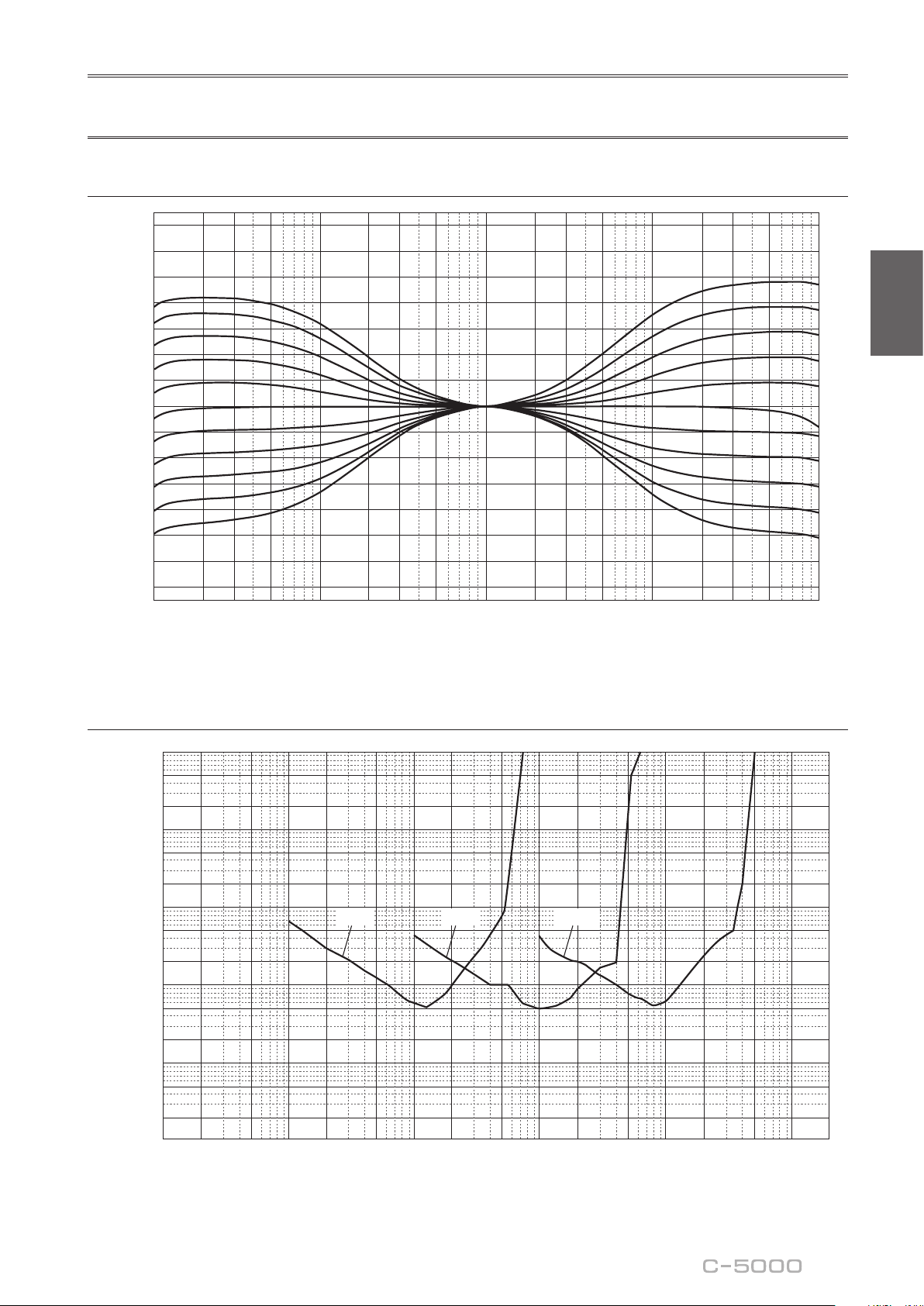
Frequency response (tone control)
Response (dB)
Frequency (Hz)
14
12
10
8
6
4
2
0
–2
–4
–6
–8
–10
–12
–14
10 20 30 50 100 200 300 500 1k 2k 3k 5k 10k 20k 30k 50k 100k
+10dB
+8dB
+6dB
+4dB
+2dB
±0dB
–2dB
–4dB
–6dB
–8dB
–10dB
Total harmonic distortion (PHONO)
10
5
2
1
0.5
0.2
0.1
0.05
0.02
0.01
0.005
0.002
0.001
0.0005
0.0002
0.0001
100µ 200µ 500µ10µ 20µ 50µ 1m 2m 5m 10m 20m
50m
100m 200m 500m
12
20 Hz 1 kHz 20 kHz
THD + N Ratio (%)
Generator Level (Vrms)
38
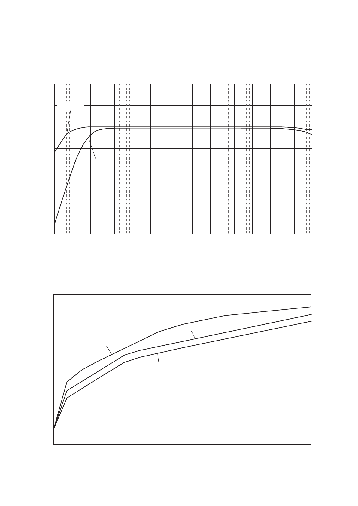
Frequency response (subsonic lter)
Response (dB)
Frequency (Hz)
10
5
0
–5
–10
–15
–20
–25
105203050 100 200 300 500 1k 2k 3k 5k 10k 20k 30k 50k 100
k
THROUGH
ON
Volume curve
Volume Level (dB)
Volume control (degree)
0
–20
–40
–60
–80
–100
–110
10
0.00 50.00 100.00 150.00 200.00 250.00
300.00
GAIN selector: –12 dB
GAIN selector: –6 dB
GAIN selector: 0 dB

39
English
Troubleshooting
Refer to the table below if this unit does not function properly. If the instructions below do not help, or if the problem
you are experiencing is not listed below, turn off the unit, disconnect the power cord, and contact the nearest authorized
Yamaha dealer or service center.
Problem Cause Remedy
See
page
Power does not turn on.
The power cord is not connected
to the AC IN connector on the
rear panel or is not plugged into
an AC outlet.
Connect the power cord firmly. 26
The unit has been exposed to
a strong external electric shock
(such as lightning or strong
static electricity).
Turn off the unit, disconnect the
power cord from the AC outlet, wait
for about 30 seconds, and then plug
the unit in again.
26
There is a problem with the
internal circuitries of this unit.
Disconnect the power cord from the
AC outlet and contact the nearest
authorized Yamaha dealer or service
center.
26
No sound is heard.
Incorrect input or output cable
connections.
Connect the cables properly. If the
problem persists, the cables might be
defective.
20
No appropriate input source has
been selected.
Select an appropriate input source
using the INPUT selector on the front
panel (or one of the input selector
keys on the remote control).
28
The OUTPUT selector setting
does not match the output jacks
that are being used.
Select an appropriate output using
the OUTPUT selector.
28
The volume level cannot
be adjusted.
EXT. DIRECT is selected as the
input source.
Adjust the volume level on the
connected component. Alternatively,
connect the external component to
a pair of the input jacks other than
the EXT. IN jacks, and then select the
corresponding input source.
20
28
Only one channel
speaker can be heard.
The playback component is not
connected properly.
Make sure that the connections are
made properly. If the problem persists,
the cables might be defective.
20

40
Problem Cause Remedy
See
page
A “humming” noise is
heard.
Incorrect input or output cable
connections.
Connect the cables properly. If the
problem persists, the cables might be
defective.
20
The turntable is not grounded to
the GND terminal.
Connect the turntable to the GND
terminal of this unit.
22
Both balanced and line cables
are being used simultaneously
between two components.
Do not use both balanced and line
cables simultaneously between two
components. Doing so would create
a ground loop that could generate
static and noise.
21
Playback audio from the
component connected
to the BAL 1 or BAL 2
balanced input jacks
sounds distorted.
The level of the signal at
the balanced input jacks is
exceeding the allowable input
level.
If the level of the signal at the XLR-
type balanced output jacks on the
connected playback component
is doubled compared to the RCA
unbalanced jacks, set the ATTENUATOR
selector located below the input jacks
to ATT. (−6 dB).
30
Bass lacks depth when
BAL 1 or BAL 2 (balanced
input) is selected.
The polarity is incorrect.
Select the correct polarity using the
PHASE selector.
14
The volume level of the
vinyl record is too low.
The PHONO switch on the front
panel is set incorrectly.
Set the PHONO switch to the MM or
MC position according to the type of
magnetic cartridge of the turntable.
29
The remote control does
not work or function
properly.
The remote control has been
used out of the operating range.
The remote control must be used
within a maximum distance of 6 m
(20 ft) and no more than 30 degrees
off-axis from the remote control
sensor on the front panel.
18
Direct sunlight or lighting (from
an inverter type of fluorescent
lamp, strobe light, etc.) is hitting
the remote control sensor on
the front panel.
Change the orientation of the lighting
or reposition the unit.
18
The batteries are weak. Replace all batteries. 18

41
English
Index
A
AC IN jack ............................... 26
Adjusting the turntable input ................. 29
ATTENUATOR selector .................... 30
AUDIO MUTE switch ..................... 31
AUTO POWER STANDBY switch ........... 13
B
BAL 1 jack ............................... 11
BAL 2 jack ............................... 11
BALANCE control ........................ 31
Balanced connection ....................... 14
BAL jack ................................ 13
BASS control ............................. 31
C
Connecting a power amplier ................ 23
Connecting a recording component ............ 22
Connecting a subwoofer .................... 23
Connecting a turntable ...................... 22
Connecting headphones ..................... 32
E
EXT. DIRECT switch ...................... 29
External In jack ........................... 23
EXT. IN jack ............................. 23
G
GAIN selector ............................ 30
Ground terminal ........................... 22
I
INPUT selector ........................... 28
L
LINE 1 jack .............................. 13
LINE 2 jack .............................. 13
LINE 2 IN jack ........................... 12
LINE 2 OUT (recording) jack ................ 12
O
OUTPUT selector ......................... 28
P
PHASE selector ........................... 14
PHONES jack ............................ 32
Phono jack ............................... 22
PHONO jack ............................. 22
PHONO selector .......................... 29
Power indicator ............................ 6
Power switch .............................. 6
R
Remote connection ........................ 25
Remote control sensor ...................... 18
REMOTE jack ............................ 25
S
SERVICE jack ............................ 13
SIGNAL GND terminal ..................... 22
Signal ground terminal ..................... 22
STANDBY/ON/OFF indicator ................ 6
STANDBY/ON/OFF switch .................. 6
SUBSONIC FILTER ....................... 30
SUBSONIC FILTER switch ................. 30
T
TREBLE control .......................... 31
Trigger connection ......................... 24
TRIGGER jack ........................... 24
TRIM selector ............................ 32
Turning the power on ........................ 6
U
Unbalanced connection ..................... 15
V
VOLUME control ......................... 30

42
Nous vous remercions et vous félicitons d’avoir choisi ce produit Yamaha.
¡
Ce préamplicateur vous permet de bénécier chez vous d’un son stéréo de haute qualité.
¡
Ce Mode d’emploi décrit les fonctions de l’appareil, les procédures de connexion et l’utilisation des
diverses fonctions.
¡
An de garantir une utilisation correcte et sûre du produit, nous vous conseillons de lire ce Mode
d’emploi ainsi que la Brochure sur la sécurité (document séparé).
Conservez ce Mode d’emploi dans un endroit sûr et facile d’accès en vue de références futures.
Vous pouvez télécharger la version électronique (PDF) de ce Mode d’emploi sur le site Internet Yamaha
ci-dessous.
https://download.yamaha.com/
Fonctions
¡
Conception gauche-droite symétrique produisant une structure en miroir
¡
Fonctionnement en classe A à tous les étages, transmission à symétrie ottante du signal de l’entrée à la
sortie
¡
Préampli phono symétrique et à masse ottante avec entrées symétriques
¡
Commandes ultra-précises intégrant une structure à roulement exclusive et sélecteurs à levier
hautement rigides
¡
Double transformateur conçu spécialement pour le son et complètement indépendant de l’alimentation
¡
Construction intégrant une masse mécanique stable réduisant considérablement l’effet des vibrations
externes
¡
Circuit de tonalité incorporant un système de volume parallèle exclusif
¡
Pieds à crampon en laiton de conception neuve
¡
Fonction de commande de gain permettant un réglage extrêmement n du volume
À propos de ce manuel
¡
Les illustrations dans ce manuel sont uniquement fournies à des ns explicatives.
¡
Les noms de sociétés et de produits gurant dans ce manuel sont des marques commerciales ou des
marques déposées de leurs détenteurs respectifs.
¡
«
AVERTISSEMENT
» décrit des précautions à suivre impérativement pour éviter les risques
de blessures graves, voire de décès.
¡
«
ATTENTION
» décrit des précautions à suivre impérativement pour éviter les risques de
blessures.
¡
«
AVIS
» décrit des précautions à suivre impérativement pour éviter les risques de dysfonctionnement/
d’endommagement de ce produit, ainsi que l’endommagement des données.
¡
«
Note
» fournit des informations complémentaires sur le produit.
¡
Avant la première utilisation de ce produit, veuillez lire le document annexe « Brochure sur la sécurité ».
Français

43
Français
Sommaire
Fonctions . . . . . . . . . . . . . . . . . . . . . . 42
À propos de ce manuel . . . . . . . . . . . . . 42
Accessoires fournis . . . . . . . . . . . . . . . . 44
Entretien. . . . . . . . . . . . . . . . . . . . . . .44
Panneaux latéraux de ni miroir. . . . . . .44
Autres surfaces. . . . . . . . . . . . . . . . . .44
Commandes et fonctions
Panneau avant . . . . . . . . . . . . . . . . . . .46
Panneau arrière . . . . . . . . . . . . . . . . . . 50
Connexions symétriques et asymétriques
. . 54
Télécommande . . . . . . . . . . . . . . . . . . 56
Mise en place des piles dans la
télécommande. . . . . . . . . . . . . . . . . .58
Utilisation de la télécommande . . . . . . . 58
Raccordements
Connexion d’un composant externe . . . . . 60
Connexion d’une platine vinyle . . . . . . . 62
Connexion d’un appareil
d’enregistrement . . . . . . . . . . . . . . . . 62
Connexion d’un autre préamplicateur . . 63
Connexion d’un amplicateur de
puissance et d’un subwoofer actif. . . . . .63
Connexions TRIGGER . . . . . . . . . . . . . . .64
Mise sous tension/hors tension synchronisée
d'un composant comme un amplicateur de
puissance connecté à cet appareil . . . . . 64
Commande de la mise sous tension et hors
tension de cet appareil depuis un composant
connecté, tel qu’un récepteur AV . . . . . . 64
Connexions à distance . . . . . . . . . . . . . .65
Commande de cet appareil depuis une
autre pièce . . . . . . . . . . . . . . . . . . . . 65
Connexion à distance entre les composants
Yamaha . . . . . . . . . . . . . . . . . . . . . . 65
Raccordement du cordon d’alimentation . .66
Utilisation des fonctions de l’appareil
Mise sous tension . . . . . . . . . . . . . . . . . 68
Choix de l’entrée et de la sortie . . . . . . . . 68
Choix du signal reçu aux prises EXT.IN . . . 69
Réglage du paramètre d’entrée de la
platine vinyle. . . . . . . . . . . . . . . . . . . .69
Sélecteur PHONO . . . . . . . . . . . . . . . . 69
Filtre subsonique . . . . . . . . . . . . . . . . 70
Réglage du niveau de volume . . . . . . . . . 70
Réduction momentanée du niveau de
volume. . . . . . . . . . . . . . . . . . . . . . .71
Réglage du timbre . . . . . . . . . . . . . . . . 71
Connexion d’un casque . . . . . . . . . . . . . 72
Références techniques
Caractéristiques générales . . . . . . . . . . . 74
Schéma fonctionnel . . . . . . . . . . . . . . . 76
Caractéristiques sonores . . . . . . . . . . . . 77
Réponse en fréquence (commande de
timbre). . . . . . . . . . . . . . . . . . . . . . .77
Distorsion harmonique totale (PHONO) . . 77
Filtre subsonique . . . . . . . . . . . . . . . . 78
Courbe de volume . . . . . . . . . . . . . . . 78
Guide de dépannage . . . . . . . . . . . . . . .79
Index . . . . . . . . . . . . . . . . . . . . . . . . . 81

44
Accessoires fournis
Veuillez vous assurer que l’emballage contient tous les éléments suivants.
• Télécommande
• Piles (AAA, R03, UM-4) (x2)
• Cordon d’alimentation
• Mode d’emploi (ce document)
• Brochure sur la sécurité (document séparé)
AVERTISSEMENT
N’utilisez pas le cordon d’alimentation fourni avec d’autres appareils.
Entretien
Pour garantir une longévité optimale de ce produit, nous vous conseillons d’en prendre soin et de l’inspecter
régulièrement.
AVERTISSEMENT
• Vériez régulièrement le cordon d’alimentation pour vous assurer qu’il n’est pas empoussiéré. Éliminez toute poussière du
cordon. Un cordon d’alimentation empoussiéré peut causer un incendie ou un choc électrique.
• N’utilisez ni aérosol ni vaporisateur de gaz inammable pour le nettoyage ou la lubrication. L’accumulation de gaz
inammable à l’intérieur de l’appareil pourrait causer une explosion ou un incendie.
AVIS
• Nettoyez la surface de l’appareil avec un chion doux et sec. L’emploi de produits de nettoyage tels que du benzène, du
diluant ou des chions imprégnés de produits chimiques pourrait causer la décoloration ou l’endommagement de la surface
de l’appareil. Si la surface de l’appareil est très encrassée, frottez-la avec un chion imbibé de détergent (dilué dans de l’eau) et
préalablement soigneusement essoré.
• Ne frottez pas avec force la zone du logo Yamaha, car celui-ci risquerait de se détacher ou des bres du chion pourraient
s’accrocher à sa surface.
Panneaux latéraux de ni miroir
Nous vous conseillons d’utiliser un chiffon de nettoyage tel que ceux pour piano. Si la surface est fort encrassée, utilisez
un chiffon doux imbibé d’eau et correctement essoré.
Autres surfaces
Nettoyez toutes les autres surfaces de l’appareil avec un chiffon
doux et sec. Si la surface de l’appareil est très encrassée,
frottez-la avec un chiffon imbibé de détergent dilué dans de
l’eau et préalablement soigneusement essoré.
Panneaux latéraux
de ni miroir

45
Français
Commandes et fonctions
Cette section décrit les noms et fonctions des éléments équipant les
panneaux avant et arrière de l’appareil, ainsi que sa télécommande.
46
Panneau avant
A.
Interrupteur/témoin STANDBY/ON/OFF
(alimentation)
Permet de mettre l’appareil sous tension (veille) et hors
tension.
STANDBY/ON
: Permet de mettre l’appareil en veille et
sous tension avec la touche
A
AMP de la télécommande.
OFF
: Met l’appareil hors tension.
Statut d’alimentation Témoin
Mode sous tension Fortement allumé
Mode veille Faiblement allumé
Mode hors tension Éteint
L’appareil entre en mode veille quand vous appuyez sur la
touche AMP de la télécommande et dans les cas suivants :
• Quand l’appareil est sous tension mais n’est pas
manipulé pendant huit heures lorsque la fonction de
mise en veille automatique est active, ou
• quand vous mettez hors tension l’appareil raccordé à la
prise TRIGGER IN de cet appareil.
Pour plus d’informations, voyez«
Q
Commutateur AUTO
POWER STANDBY » dans la section « Panneau arrière »
(page 53) et « Connexions TRIGGER » (page 64).
Note
Après la mise sous tension de l’appareil, celui-ci met
quelques secondes à restituer le son.
AVIS
Si vous ne comptez pas utiliser l’appareil pendant une
période prolongée, débranchez son cordon d’alimentation
de la prise de courant. Même quand l’appareil est mis
hors tension avec son commutateur STANDBY/ON/OFF
(alimentation), une faible quantité de courant électrique
transite toujours dans l’appareil.
B.
Capteur de télécommande
Il reçoit les signaux émis par la télécommande. Pour plus
d’informations, voyez « Utilisation de la télécommande »
(page 58).
C.
Prise PHONES
Branchez un casque à cette prise pour écouter de la
musique sans déranger votre entourage. Pour plus
d’informations, voyez « Connexion d’un casque »
(page 72).

47
Français
D.
Sélecteur TRIM
Permet de sélectionner le gain de l’amplicateur de
casque. L’unité règle le niveau de volume quand vous
branchez un casque pour éviter tout changement de
volume brusque en modiant l’équilibre de niveau entre
le signal à la prise PHONES et aux enceintes.
Choix
: −6 dB, 0 dB, +6 dB, +12 dB
E.
Sélecteur GAIN
Permet de sélectionner le gain du préamplicateur. Vous
pouvez ainsi adapter parfaitement l’appareil au gain
de l’amplicateur de puissance et à la sensibilité des
enceintes, et effectuer des réglages précis de volume.
Pour plus d’informations, voyez « Réglage du niveau de
volume » (page 70).
Choix
: −12 dB, −6 dB, 0 dB
F.
Sélecteur OUTPUT
Permet de déterminer quelles prises OUTPUT produisent
des signaux comme suit :
Utilisez ce sélecteur lorsque plusieurs amplicateurs de
puissance sont raccordés.
Sélecteur OUTPUT
OFF ALL BAL LINE1 LINE2
Prises
BAL
—
Signal
présent
Signal
présent
— —
Prises
LINE 1
—
Signal
présent
—
Signal
présent
—
Prises
LINE 2
—
Signal
présent
— —
Signal
présent
G.
Sélecteur PHONO
Permet de spécier le type de cellule installée sur la
platine vinyle raccordée aux prises PHONO du panneau
arrière (
M, MC 300, MC 100, MC 30, MC 10
).
Pour plus d’informations, voyez « Réglage du paramètre
d’entrée de la platine vinyle » (page 69).
AVIS
Avant de remplacer la cellule, veillez à mettre cet appareil
hors tension.
48
H.
Commande BASS
Règle la réponse du grave sur une plage de −10 dB
à +10 dB (par pas de 0,5 dB). La position centrale
correspond à une réponse plate.
I.
Commande TREBLE
Règle la réponse de l’aigu sur une plage de −10 dB
à +10 dB (par pas de 0,5 dB). La position centrale
correspond à une réponse plate.
J.
Commande BALANCE
Équilibre le niveau de volume des enceintes gauche et
droite de L (le signal de la voie droite est inaudible) à R (le
signal de la voie gauche est inaudible) pour compenser
des différences de niveau causées par l’emplacement des
enceintes ou l’acoustique de la pièce d’écoute.
K.
Commutateur/témoin EXT. DIRECT
Quand vous appuyez une fois sur le commutateur
EXT. DIRECT, le témoin EXT. DIRECT s’allume et
le signal de la source d’entrée audio reçu aux prises
EXT. IN est transmis aux prises de sortie reliées. Pour
plus d’informations, voyez « Connexion d’un autre
préamplicateur » (page 63) et « Choix de l’entrée et
de la sortie » (page 68).
Quand vous appuyez à nouveau sur le commutateur EXT.
DIRECT ou tournez le sélecteur INPUT, le signal choisi
avec le sélecteur INPUT est choisi comme source d’entrée
et le témoin EXT. DIRECT s’éteint.
Note
Quand EXT. DIRECT est sélectionné, aucun signal n’est
restitué via les prises LINE 2 OUT (enregistrement) et la
prise PHONES.
Panneau avant

49
Français
L.
Sélecteur/Témoin INPUT
Permet de sélectionner la source audio que vous souhaitez
lire. Vous pouvez choisir parmi les sources suivantes :
PHONO, PHONO BAL, TUNER, CD, BAL 1, BAL 2, LINE 1 et
LINE 2
.
Le témoin de la source d’entrée choisie s’allume.
Note
Si vous choisissez la source d’entrée LINE 2 avec ce
sélecteur, aucun signal n’est restitué via les prises LINE 2
OUT (enregistrement).
M.
Commutateur SUBSONIC FILTER
Bascule entre la position
ON
(activée) et
THROUGH
(désactivée) du ltre subsonique. Pour plus
d’informations, voyez « Réglage du paramètre d’entrée
de la platine vinyle » (page 69).
Note
Si le sélecteur INPUT est placé sur toute position autre que
PHONO ou PHONO BAL, le ltre est désactivé.
N.
Commutateur/témoin AUDIO MUTE
Appuyez sur ce commutateur pour réduire le niveau
sonore d’environ 20 dB. Le témoin s’allume. Appuyez
à nouveau sur ce commutateur pour rétablir le niveau
sonore initial. Le témoin s’éteint.
O.
Commande VOLUME
Règle le niveau de volume. Ce réglage n’affecte pas
le niveau du signal restitué via les prises LINE 2 OUT
(enregistrement).
Note
Le réglage de la commande VOLUME n’aecte pas le niveau
sonore lorsque EXT. DIRECT est sélectionné comme source
d’entrée. Pour régler le volume, utilisez la commande
de volume du préamplicateur externe ou d’un autre
composant raccordé aux prises EXT. IN.
P.
Pieds
Si l’appareil n’est pas stable, ajustez sa hauteur en
tournant ses pieds.

50
Note
Pour des informations sur la procédure de connexion, voyez
« Raccordements » (page59).
A.
Prises PHONO
Prises de types RCA (Cinch) et XLR. Quand le sélecteur
INPUT est réglé sur PHONO, la source d’entrée
correspond au signal reçu via les prises PHONO RCA
(Cinch). Quand le sélecteur INPUT est réglé sur PHONO
BAL, la source d’entrée correspond au signal reçu via les
prises PHONO XLR.
Ce préamplicateur est fourni avec un capuchon de court-
circuitage xé sur chaque prise d’entrée PHONO RCA
(Cinch). Si vous comptez brancher un composant externe
à ces prises, retirez les capuchons de court-circuitage.
Pour plus d’informations, voyez « Connexion d’une
platine vinyle » (page 62).
PHONO
ATTENTION
Manipulez les capuchons de court-circuitage avec soin.
Ne laissez jamais des enfants jouer avec les capuchons de
court-circuitage car cela poserait un risque d’ingestion.
AVIS
• Les capuchons de court-circuitage sont UNIQUEMENT
destinés aux ENTRÉES inutilisées. Ne les utilisez jamais
avec les SORTIES car cela risquerait d’endommager vos
appareils.
• Si vous n’utilisez pas les prises d’entrée PHONO de type
RCA (Cinch), insérez les capuchons de court-circuitage
dans ces prises pour éviter que des parasites ou du bruit
aléatoires ne dégradent le signal audio.
B.
Borne SIGNAL GND (masse)
Si vous branchez votre platine vinyle aux prises d’entrée
PHONO de type RCA (Cinch), raccordez aussi la platine
vinyle à cette borne. Cela peut contribuer à réduire le
bruit.
Panneau arrière

51
Français
C.
Prises BAL 1/BAL 2
Il s’agit de deux jeux de prises d’entrée symétrique de
type XLR. Quand le sélecteur INPUT est réglé sur BAL
1 ou BAL 2, la source d’entrée correspond au signal reçu
via les prises XLR en question.
Note
Réglez le sélecteur ATTENUATOR et le sélecteur PHASE de
façon appropriée en fonction des dispositifs de lecture
raccordés à cet appareil.
D.
Sélecteur ATTENUATOR
Permet de dénir le niveau d’entrée admissible du signal
reçu aux prises d’entrée XLR symétriques (prises BAL 1
et BAL 2). Pour plus d’informations, voyez « Réglage du
niveau de volume » (page 70).
BYPASS
: Le niveau d’entrée admissible n’est pas atténué.
C’est la position adoptée en temps normal.
ATT. (−6 dB)
: Le gain d’entrée est atténué de 6 dB pour
permettre la réception d’un signal d’entrée de niveau plus
élevé. Choisissez cette position lorsque le signal de la
source connectée comporte de la distorsion.
E.
Sélecteur PHASE
Permet de dénir la position de la broche point CHAUD
des prises d’entrée XLR symétriques (prises BAL 1 et
BAL 2).
NORMAL
: La broche 2 correspond au point CHAUD.
INV.
: La broche 3 correspond au point CHAUD.
Pour plus d’informations, voyez « Connexions
symétriques et asymétriques » (page 54).
F.
Prises TUNER
Il s’agit de prises d’entrée RCA (Cinch). Quand le
sélecteur INPUT est réglé sur TUNER, la source d’entrée
correspond au signal reçu via ces prises. Branchez votre
syntoniseur à ces prises.
52
G.
Prises CD
Il s’agit de prises d’entrée RCA (Cinch). Quand le
sélecteur INPUT est réglé sur CD, la source d’entrée
correspond au signal reçu via ces prises. Branchez votre
lecteur CD à ces prises.
H.
Prises LINE 1
Il s’agit de prises d’entrée RCA (Cinch). Quand le
sélecteur INPUT est réglé sur LINE 1, la source d’entrée
correspond au signal reçu via ces prises.
I.
Prises LINE 2 IN
Il s’agit de prises d’entrée RCA (Cinch). Quand le
sélecteur INPUT est réglé sur LINE 2, la source d’entrée
correspond au signal reçu via ces prises.
J.
Prises LINE 2 OUT (enregistrement)
Il s’agit de prises d’entrée RCA (Cinch) destinées à
l’enregistrement. Ces prises restituent en principe les
signaux de la source d’entrée sélectionnée en face avant
ou avec la télécommande. Pour des informations sur
la procédure de connexion, voyez « Connexion d’un
appareil d’enregistrement » (page 62).
Note
• Raccordez les prises LINE 2 IN et LINE 2 OUT
(enregistrement) au même composant.
• Les prises LINE 2 OUT (enregistrement) ne restituent
aucun signal si le sélecteur INPUT est la position LINE 2
ou le commutateur EXT. DIRECT est enfoncé.
K.
Prises EXT.IN
Il s’agit de prises d’entrée de types XLR et RCA (Cinch).
Quand le commutateur EXT. DIRECT est enfoncé,
la source d’entrée correspond au signal reçu via ces
prises. Branchez votre préamplicateur à ces prises.
Pour plus d’informations, voyez « Connexion d’un autre
préamplicateur » (page 63).
ATTENTION
Vous ne pouvez pas régler le volume des signaux reçus aux
prises EXT. IN. Veillez donc à raccorder les prises EXT. IN à
un composant comportant une commande de volume.
Panneau arrière

53
Français
Note
Le niveau de volume est xe. En conséquence, les réglages de
la commande VOLUME ou du sélecteur GAIN de cet appareil
n’inuencent pas le niveau de volume du signal reçu aux
prises EXT. IN. Réglez le niveau de volume avec la commande
de volume du composant raccordé aux prises EXT. IN.
L.
Prises BAL
Il s’agit de prises de sortie de type XLR. Raccordez ces
prises aux prises d’entrée symétrique de l’amplicateur
de puissance.
M.
Prises LINE 1/LINE 2
Il s’agit de prises de sortie RCA (Cinch). Raccordez ces
prises aux prises d’entrée RCA (Cinch) de l’amplicateur
de puissance.
N.
Prises TRIGGER IN/TRIGGER OUT
Il s’agit de prises minijack mono. Branchez à ces prises
des composants externes compatibles avec la fonction
de déclenchement (Trigger). Pour plus d’informations,
voyez « Connexions TRIGGER » (page 64).
O.
Prises REMOTE IN/REMOTE OUT
Il s’agit de prises minijack mono. Branchez à ces prises
des composants externes compatibles avec la fonction
de commande à distance. Pour plus d’informations,
voyez « Connexions à distance » (page 65).
P.
Prise SERVICE
Cette prise est utilisée pour l’entretien de l’appareil. Elle
est rarement utilisée.
Q.
Commutateur AUTO POWER STANDBY
Détermine si la fonction de mise en veille automatique de
l’appareil est active ou non.
ON
:
L’appareil entre automatiquement en mode veille s’il
est sous tension mais n’est pas manipulé pendant huit heures.
OFF
: L’appareil n’entre pas automatiquement en mode
veille.
R.
Prise AC IN
Branchez le cordon d’alimentation fourni à cette prise.
Pour plus d’informations, voyez « Raccordement du
cordon d’alimentation » (page 66).

54
Connexions symétriques et
asymétriques
Cet appareil est doté de prises d’entrée symétrique de
type XLR et asymétrique de type RCA (Cinch).
Note
N’utilisez pas simultanément une connexion symétrique
et une connexion asymétrique entre deux appareils. Cela
génère une boucle de masse susceptible de causer des
interférences et du bruit.
Connexion symétrique
Les connexions symétriques sont conçues pour supprimer
et prévenir tout bruit indésirable. Vu que les câbles
relativement longs ont tendance à générer davantage de
bruit, il est conseillé d’utiliser une connexion symétrique
pour connecter ce type de câbles. De manière générale, si
vos composants sont dotés de sorties symétriques, il est
conseillé de les raccorder via une connexion symétrique.
Prises de connexion symétrique
Les prises de type XLR de cet appareil sont utilisées pour
des connexions symétriques. Les prises d’entrée et de
sortie sont différentes. Les prises d’entrée sont femelles et
les prises de sortie mâles. Pour effectuer des connexions
symétriques, on utilise des câbles symétriques à ches
XLR. Raccordez la che mâle du câble à une prise
femelle de l’appareil et sa che femelle à une prise mâle
de l’appareil.
3
2
2
1
1
3
Levier
Fiche XLR (mâle)Prise XLR (femelle)
Pour brancher un câble à une prise d’entrée, alignez
les broches de la che avec les orices de la prise,
puis insérez la che dans la prise jusqu’à ce que vous
entendiez un déclic. Pour débrancher le câble, appuyez
sur le levier de la prise d’entrée de l’appareil tout en
tirant la che XLR mâle du câble hors de la prise.
3
1
1
2
2
3
Fiche XLR (femelle)Prise XLR (mâle)
Levier
Pour brancher un câble à une prise de sortie, alignez
les orices de la che avec les broches de la prise,
puis insérez la che dans la prise jusqu’à ce que vous
entendiez un déclic. Pour débrancher le câble, appuyez
sur le levier de la prise XLR femelle tout en tirant la che
du câble XLR hors de la prise.
Polarité de connexion symétrique
Dans le cas d’une connexion symétrique, il est impératif
de régler correctement la polarité. En général, la broche
2 correspond au point chaud, mais dans certains cas c’est
la broche 3. Vériez quelle broche correspond au point
chaud sur la prise de sortie dans le mode d’emploi du
composant raccordé.
Réglez la polarité des prises d’entrée BAL 1 et BAL 2
avec le sélecteur PHASE du panneau arrière.
Note
• Les prises PHONO et EXT. IN ne comportent pas de
sélecteur PHASE. Les broches de ces prises ont une
polarité conventionnelle et xe.
• La broche 2 correspond au point chaud sur les lecteurs
Yamaha.

55
Français
Quand le sélecteur PHASE est sur la position NORMAL,
la broche 2 correspond au point chaud.
Prise d’entrée de type XLR
1 : Masse (terre)
3 : Point froid (−)
2 : Point chaud
(+)
Levier
Quand le sélecteur PHASE est sur la position
INVERTED, la broche 3 correspond au point chaud.
Prise d’entrée de type XLR
1 : Masse (terre)
3 : Point chaud (+)
2 : Point froid
(−)
Levier
Prise de sortie de type XLR
1 : Masse (terre)
3 : Point froid (−)
2 : Point chaud
(+)
Connexion asymétrique
Si vous raccordez un composant audio uniquement doté
de prises standard RCA (Cinch), utilisez les prises RCA
de cet appareil pour effectuer une connexion asymétrique.
Pour effectuer des connexions asymétriques, on utilise
des câbles asymétriques à ches RCA (Cinch). Ces ches
et prises ne présentent pas de différence mâle/femelle ni
de différence de polarité.
Broche
Anneau

56
Télécommande
A.
Émetteur de signal infrarouge
Transmet des signaux infrarouges de commande à
l’appareil.
B.
Touche
A
AMP
Met l’appareil sous tension ou le bascule en mode veille.
Pour plus d’informations sur le mode veille, voyez
« Panneau avant » (page 46).
C.
Touches de sélection d’entrée
Permettent de sélectionner la source audio à lire.
BAL
: Sélectionne le composant raccordé aux prises XLR
BAL 1 ou BAL 2 comme source d’entrée.
PHONO
: Sélectionne la platine vinyle raccordée aux
prises PHONO (XLR ou RCA) comme source d’entrée.
Appuyez sur la touche BAL pour sélectionner la source
raccordée aux prises XLR ou sur la touche UNBAL pour
sélectionner la source raccordée aux prises RCA (Cinch).
LINE
: Sélectionne le composant raccordé aux prises RCA
(Cinch) LINE 1 ou LINE 2 comme source d’entrée.
EXT.
DIRECT
: Sélectionne le composant branché aux
prises EXT. IN comme source d’entrée. Quand EXT.
DIRECT est sélectionné comme source d’entrée, les
signaux audio ne sont pas transmis aux prises LINE 2
OUT et PHONES.
CD
: Sélectionne le composant (généralement un lecteur
CD) raccordé aux prises RCA (Cinch) CD comme source
d’entrée.
TUNER
: Sélectionne le composant (généralement un
syntoniseur) raccordé aux prises RCA (Cinch) TUNER
comme source d’entrée.
Note
Les signaux audio de la source d’entrée sélectionnée sont
restitués via les prises LINE 2 OUT (enregistrement). Si LINE
2 est sélectionné comme source d’entrée, aucun signal n’est
restitué via les prises LINE 2 OUT (enregistrement).
D.
Touches de commande du syntoniseur
Permettent de commander les fonctions du syntoniseur
Yamaha raccordé. La touche BAND sert à choisir la
bande de réception et les touches PRESET
er
une
présélection. Pour plus d’informations, consultez le mode
d’emploi de votre syntoniseur.
Note
Il se pourrait que certains modèles de syntoniseur Yamaha
ne prennent pas en charge les fonctions de ces touches.
AMP CD
BAL
PHONO
LINE
CD
TUNER BAND
PRESET
SOURCE LAYER
EXT.DIRECT
BALUNBAL
21
21
OPEN/CLOSE
VOLUME
MUTE

57
Français
E.
Touche
A
CD
Met le lecteur CD Yamaha raccordé sous tension ou le
bascule en mode veille.
F.
Touche OPEN/CLOSE
Ouvre ou ferme le tiroir du lecteur CD Yamaha raccordé.
Pour plus d’informations, consultez le mode d’emploi de
votre lecteur CD.
Note
Il se pourrait que certains modèles de lecteur CD Yamaha
ne prennent pas en charge les fonctions de la touche
A
CD
et/ou la touche
OPEN/CLOSE.
G.
Touches de commande du lecteur de
CD
Permettent de commander les fonctions du lecteur CD
Yamaha raccordé. Pour plus d’informations, consultez le
mode d’emploi de votre lecteur CD.
(Lecture)
Démarre la lecture.
(Pause)
Met la lecture en pause. Appuyez sur ou pour
poursuivre la lecture.
(Arrêt)
Arrête la lecture.
/ (Saut de plage)
Passe à la plage suivante ou retourne au début de la
plage actuelle.
Touche SOURCE
Sélectionne la source à lire sur le lecteur CD Yamaha.
La source de lecture change à chaque pression de cette
touche.
Touche LAYER
Commute la couche de lecture d’un CD Super Audio
hybride entre « Super audio CD » et « CD ».
Note
Il se pourrait que certains modèles de lecteur CD Yamaha
ne prennent pas en charge les fonctions de ces touches.
H.
Touches VOLUME +/−
Règlent le niveau de volume.
Note
Les touches VOLUME +/− de la télécommande n’aectent
pas le niveau de volume lorsque EXT. DIRECT est
sélectionné comme source d’entrée. Pour régler le volume,
utilisez la commande de volume de l’amplicateur externe
raccordé aux prises EXT. IN.
I.
Touche MUTE
Réduit le niveau sonore actuel d’environ 20 dB. Appuyez
à nouveau sur cette touche pour rétablir le niveau sonore
initial. Vous pouvez aussi annuler la réduction du niveau
sonore en appuyant sur la touche VOLUME + ou − de la
télécommande.

58
Mise en place des piles dans la
télécommande
1
Retirez le couvercle du logement des piles.
2
Insérez deux piles (AAA, R03, UM-4) en
suivant les repères de polarité (+ et −) à
l’intérieur du logement des piles.
1
2
3
Replacez le couvercle du logement des
piles.
3
AVERTISSEMENT
• Ne jetez pas des piles dans un feu ouvert et ne les
exposez pas à des températures élevées, comme en
plein soleil ou à proximité d’une amme nue. Sinon, les
piles risquent d’exploser et de causer un incendie ou des
blessures.
• N’essayez jamais de recharger des piles non
rechargeables. Sinon, les piles risqueraient d’exploser ou
de fuir, causant la cécité, des brûlures chimiques ou des
blessures.
• Si une pile fuit, ne touchez jamais le liquide. Sinon, cela
pourrait causer la cécité ou des brûlures chimiques. Si
les yeux, la bouche ou la peau entre en contact avec
le liquide fuyant des piles, rincez immédiatement et
abondamment à l’eau et consultez un médecin.
ATTENTION
• Ne mélangez pas des piles neuves et des piles usagées.
Sinon, cela pourrait causer un incendie, des brûlures
ou une irritation cutanée due au contact avec le liquide
fuyant des piles.
• Ne mélangez pas diérents types de piles. Ainsi, par
exemple, si vous utilisez simultanément une pile au
manganèse et une pile alcaline, ou deux piles de
fabricants diérents ou encore de numéros de produit
diérents, cela pourrait causer un incendie, des brûlures
ou une irritation cutanée due au contact avec le liquide
fuyant des piles.
• Conservez les piles hors de portée des enfants. Sinon,
un enfant risquerait d’avaler accidentellement une pile.
En outre, le liquide fuyant des piles pourrait causer une
irritation cutanée.
• Insérez les deux piles en respectant les indications de
polarité (+ et −). Sinon, cela pourrait causer un incendie,
des brûlures ou une irritation cutanée due au contact
avec le liquide fuyant des piles.
• Si vous ne comptez pas utiliser la télécommande
pendant une période prolongée ou si les piles sont
complètement plates, retirez-les de la télécommande.
Sinon, les piles niront par s’épuiser complètement et
risqueront de fuir en causant une irritation cutanée ou
un endommagement de la télécommande.
Utilisation de la télécommande
Pour utiliser la télécommande, pointez-la directement
vers le capteur de télécommande sur le panneau avant de
l’appareil.
Capteur de
télécommande
30 30
Dans un rayon
de 6 mètres

59
Français
Raccordements
ATTENTION
Mettez tous les appareils hors tension avant d’eectuer toute connexion.
AVIS
• N’utilisez pas simultanément une connexion symétrique et une connexion asymétrique entre deux appareils. Cela génère une
boucle de masse susceptible de causer des interférences et du bruit.
• Si vous comptez brancher des appareils externes, lisez au préalable les manuels de ces appareils et suivez leurs consignes.
Sinon, vous risquez un dysfonctionnement de cet appareil ou des composants externes.
Cette section décrit la connexion de l’appareil à une source audio
comme un lecteur CD, ainsi qu’à un amplicateur de puissance.

60
Connexion d’un composant externe
Platine vinyle
Lecteur réseau
Lecteur CD
Enregistreur à disque dur,
etc.
Syntoniseur
Lecteur CDPlatine vinyle Lecteur BD

61
Français
AVIS
N’utilisez pas simultanément une connexion symétrique et une connexion asymétrique entre deux appareils. Cela génère une
boucle de masse susceptible de causer des interférences et du bruit.
Amplicateur de puissanceAutre préamplicateur
Amplicateur AV, etc.
Subwoofer actif
Amplicateur de puissance

62
Connexion d’une platine vinyle
Branchez la platine vinyle aux prises PHONO de
cet appareil. Cet appareil est doté de prises d’entrée
symétrique de type XLR et asymétrique de type RCA
(Cinch).
Connexion symétrique
L
R
OUTPUT
(
BALANCE
)
Platine vinyle
Connexion asymétrique
L
R
OUTPUT
Platine vinyle
Note
Si vous raccordez la platine vinyle aux prises RCA (Cinch)
de cet appareil, faites un test et comparez le son obtenu
avec la borne SIGNAL GND (de masse) raccordée et non
raccordée, et choisissez la méthode de connexion orant le
moins de bruit.
AVIS
N’utilisez pas simultanément une connexion symétrique et
une connexion asymétrique entre cet appareil et la platine
vinyle. Cela génère une boucle de masse susceptible de
causer des interférences et du bruit.
Connexion d’un appareil
d’enregistrement
Vous pouvez raccorder un appareil d’enregistrement
comme un enregistreur à disque dur à cet appareil pour
capturer le signal reçu d’une source externe. Raccordez
l’appareil d’enregistrement aux prises LINE 2 IN et LINE
2 OUT (enregistrement).
Note
• Veillez à raccorder les prises LINE 2 IN et LINE 2 OUT
(enregistrement) au même composant.
• Le signal restitué aux prises LINE 2 OUT (enregistrement)
est quasi identique au signal aux prises de sortie choisies
avec le sélecteur OUTPUT. Quand le sélecteur INPUT est
réglé sur LINE 2, aucun signal n’est restitué par les prises
LINE 2 OUT (enregistrement).
L
R
L
R
OUTPUT
INPUT
Enregistreur à
disque dur, etc.
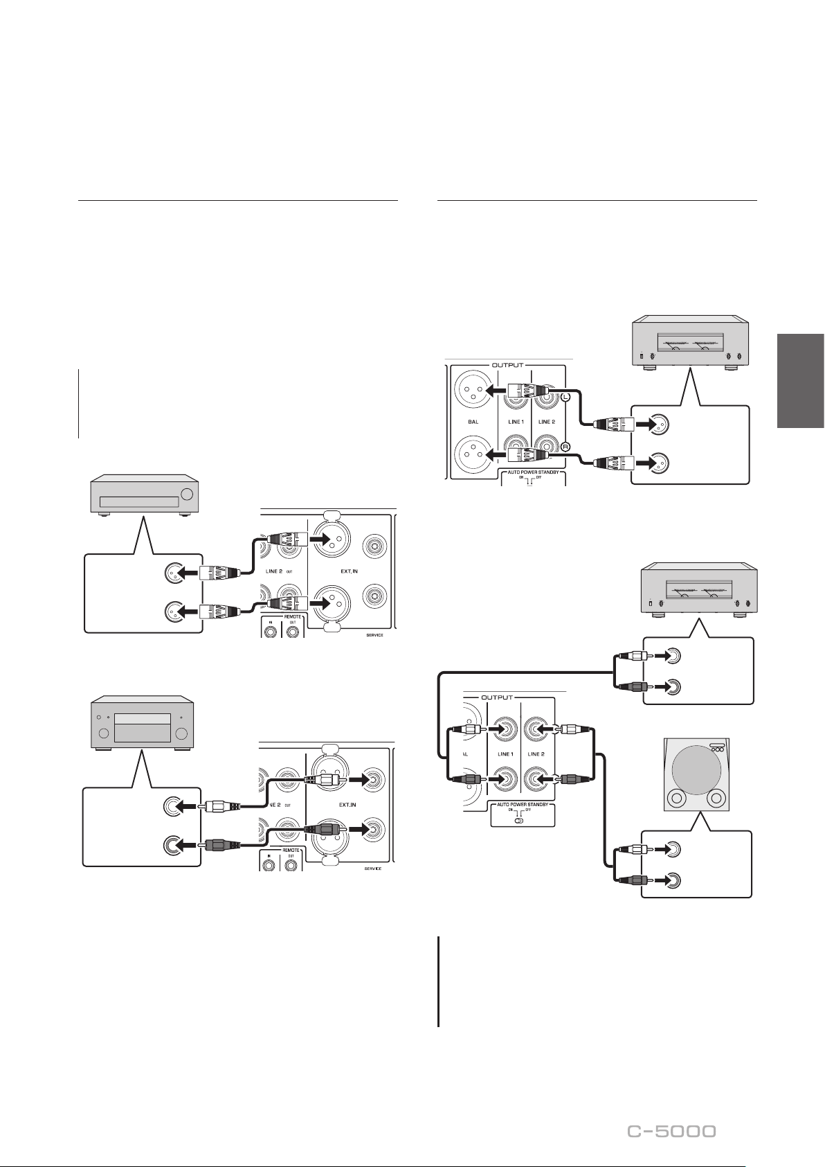
63
Français
Connexion d’un autre
préamplicateur
Si vous raccordez la sortie d’un autre préamplicateur
aux prises EXT. IN de cet appareil et appuyez sur le
commutateur EXT. DIRECT, le signal de la source
transite par cet appareil et est transmis à l’amplicateur
de puissance raccordé. Le signal de la source reçu aux
prises symétriques EXT. IN est transmis aux prises
symétriques BAL. Le signal de la source reçu aux prises
asymétriques EXT. IN est transmis aux prises LINE 1 et
LINE 2.
Note
Quand le commutateur EXT. DIRECT est actif, aucun signal
n’est présent à la prise PHONES et vous n’entendez donc
rien dans le casque connecté.
L
R
OUTPUT
(
BALANCE
)
Autre préamplicateur
L
R
PREOUT
Amplicateur AV, etc.
Connexion d’un amplicateur de
puissance et d’un subwoofer actif
Vous pouvez raccorder un amplicateur de puissance et
un subwoofer actif (amplié) aux prises de sortie BAL,
LINE 1 ou LINE 2 de l’appareil.
Connexion symétrique
L
R
INPUT
(
BALANCE
)
Amplicateur de
puissance
Connexion asymétrique
L
R
INPUT
(
UNBALANCE
)
L
R
INPUT
(
UNBALANCE
)
Amplicateur de
puissance
Subwoofer actif
AVIS
N’utilisez pas simultanément une connexion symétrique
et une connexion asymétrique entre deux appareils. Cela
génère une boucle de masse susceptible de causer des
interférences et du bruit.

64
Connexions TRIGGER
Mise sous tension/hors tension
synchronisée d'un composant
comme un amplicateur de
puissance connecté à cet
appareil
Cette fonction permet de mettre sous tension et hors
tension un composant Yamaha comme un lecteur CD
ou amplicateur de puissance connecté à cet appareil en
même temps que ce dernier.
Raccordez la prise TRIGGER OUT de cet appareil à la
prise TRIGGER IN du composant raccordé avec un câble
système.
Lecteur CD
Amplicateur de
puissance
Prise TRIGGER IN
Prise
TRIGGER
IN
Commande de la mise sous
tension et hors tension de cet
appareil depuis un composant
connecté, tel qu’un récepteur AV
Vous pouvez commander la mise sous tension et hors
tension de cet appareil depuis un composant connecté,
tel qu’un récepteur AV Yamaha. Raccordez la prise
TRIGGER IN de cet appareil à la prise TRIGGER OUT
du composant raccordé avec un câble système en option.
Quand cet appareil est en veille, la mise sous tension du
composant connecté met aussi cet appareil sous tension,
et le signal reçu aux prises EXT. IN est sélectionné
comme source d’entrée. Quand le composant connecté
est mis hors tension, cet appareil entre en veille.
Récepteur AV
Prise
TRIGGER
OUT
Note
• Si l’interrupteur d’alimentation de cet appareil est en
position OFF, la commande à distance de l’alimentation
depuis un composant connecté n’est pas possible.
• Si la source d’entrée n’est pas sélectionnée avec le
commutateur EXT. DIRECT, la mise hors tension du
composant connecté ne permet pas de mettre cet
appareil hors tension.

65
Français
Connexions à distance
Commande de cet appareil
depuis une autre pièce
Si vous branchez un récepteur et un émetteur infrarouge
aux prises REMOTE IN/OUT de cet appareil, vous
pouvez utiliser l’appareil et/ou le composant externe à
l’aide du boîtier de télécommande fourni.
Composant externe
(lecteur CD, etc.)
Télécommande
Émetteur
infrarouge
Récepteur
infrarouge
Connexion à distance entre les
composants Yamaha
Lorsque vous avez un autre composant Yamaha prenant
en charge la connexion à distance, comme c’est le cas
pour cet appareil, un émetteur infrarouge est inutile.
Vous pouvez transmettre les signaux de connexion à
distance en raccordant un récepteur infrarouge à la prise
REMOTE IN de l’appareil et en reliant la prise REMOTE
IN de l’autre composant à la prise REMOTE OUT de cet
appareil avec des câbles minijack mono. Vous pouvez
relier jusqu’à trois composants Yamaha (y compris cet
appareil) avec la connexion à distance.
REMOTE
IN OUT
Composant Yamaha
(jusqu’à troiscomposants,
cet appareil compris)
Télécommande
Câble à ches minijack
mono
Récepteur
infrarouge

66
Raccordement du cordon d’alimentation
Quand toutes les connexions sont terminées, vériez que
l’interrupteur STANDBY/ON/OFF (alimentation) est sur
OFF, puis raccordez le cordon d’alimentation à la prise AC
IN de l’appareil et la che secteur du cordon à une prise de
courant.
Vers une prise
secteur
C-5000
Panneau arrière
Cordon
d’alimentation
fourni
AVERTISSEMENT
• Si vous Notez une des anomalies suivantes, mettez
immédiatement l’appareil hors tension et débranchez
son cordon d’alimentation de la prise de courant.
- Le cordon d’alimentation ou sa che est endommagé.
- L’appareil émet une odeur, un bruit anormal ou de la
fumée.
- Du liquide ou des objets ont pénétré à l’intérieur de
l’appareil.
- Le son est brusquement coupé durant le
fonctionnement de l’appareil.
- Le châssis de l’appareil est ssuré ou endommagé.
Si vous continuez d’utiliser l’appareil quand il présente
un de ces symptômes, cela pourrait causer un choc
électrique, un incendie ou un dysfonctionnement.
Contactez le revendeur ou SAV Yamaha le plus proche
pour faire vérier ou réparer l’appareil.
• Ne touchez jamais le cordon d’alimentation ni sa che
durant un orage. Sinon, vous risqueriez d’être électrocuté.
• Veillez à brancher l’appareil à une prise de courant
fournissant la tension correcte mentionnée sur l’appareil.
La connexion de l’appareil à une prise de courant de
tension inappropriée peut causer un incendie, un choc
électrique ou un dysfonctionnement.
• Utilisez uniquement le cordon d’alimentation fourni.
N’utilisez pas le cordon d’alimentation fourni avec
d’autres appareils. Sinon, cela pourrait causer un
incendie, des brûlures ou un dysfonctionnement.
• Branchez l’appareil à une prise de courant visible et
facile d’accès, de sorte à pouvoir débrancher l’appareil
rapidement et facilement en cas d’urgence. À moins que
vous ne débranchiez l’appareil du secteur, une faible
quantité de courant électrique transite toujours dans
l’appareil quand il est hors tension.
• En cas de risque d’orage, mettez immédiatement
l’appareil hors tension et débranchez son cordon
d’alimentation de la prise de courant. Sinon, cela pourrait
causer un incendie ou un dysfonctionnement.
• Si vous ne comptez pas utiliser l’appareil pendant
une période prolongée, débranchez son cordon
d’alimentation de la prise de courant. Sinon, cela pourrait
causer un incendie ou un dysfonctionnement.
ATTENTION
• N’utilisez pas de prise de courant ne permettant pas de
brancher fermement la che du cordon d’alimentation.
Sinon, cela pourrait causer un incendie, un choc
électrique ou des brûlures.
• Saisissez toujours la che du cordon d’alimentation pour
le débrancher de la prise de courant ; ne tirez jamais sur
le cordon. Sinon, vous risquez d’endommager le cordon
d’alimentation, ce qui pourrait causer un choc électrique
ou un incendie.
• Insérez la che du cordon d’alimentation fermement et
jusqu’au bout dans la prise de courant. Si la che n’est
pas insérée à fond dans la prise de courant, l’utilisation
de l’appareil pourrait causer un choc électrique. En outre,
de la poussière pourrait s’accumuler sur la che et poser
un risque d’incendie ou de brûlures.
AVIS
Si vous ne comptez pas utiliser l’appareil pendant une
période prolongée, débranchez son cordon d’alimentation
de la prise de courant. Même quand l’appareil est mis hors
tension avec son interrupteur STANDBY/ON/OFF (le témoin
d’alimentation est éteint), une faible quantité de courant
électrique transite toujours dans l’appareil.

67
Français
Utilisation des fonctions
de l’appareil
Cette section décrit les manipulations de base de l’appareil.
Suivez ces procédures pour découvrir les fonctions de cet appareil.
Ces procédures sont uniquement fournies à titre d’exemple.
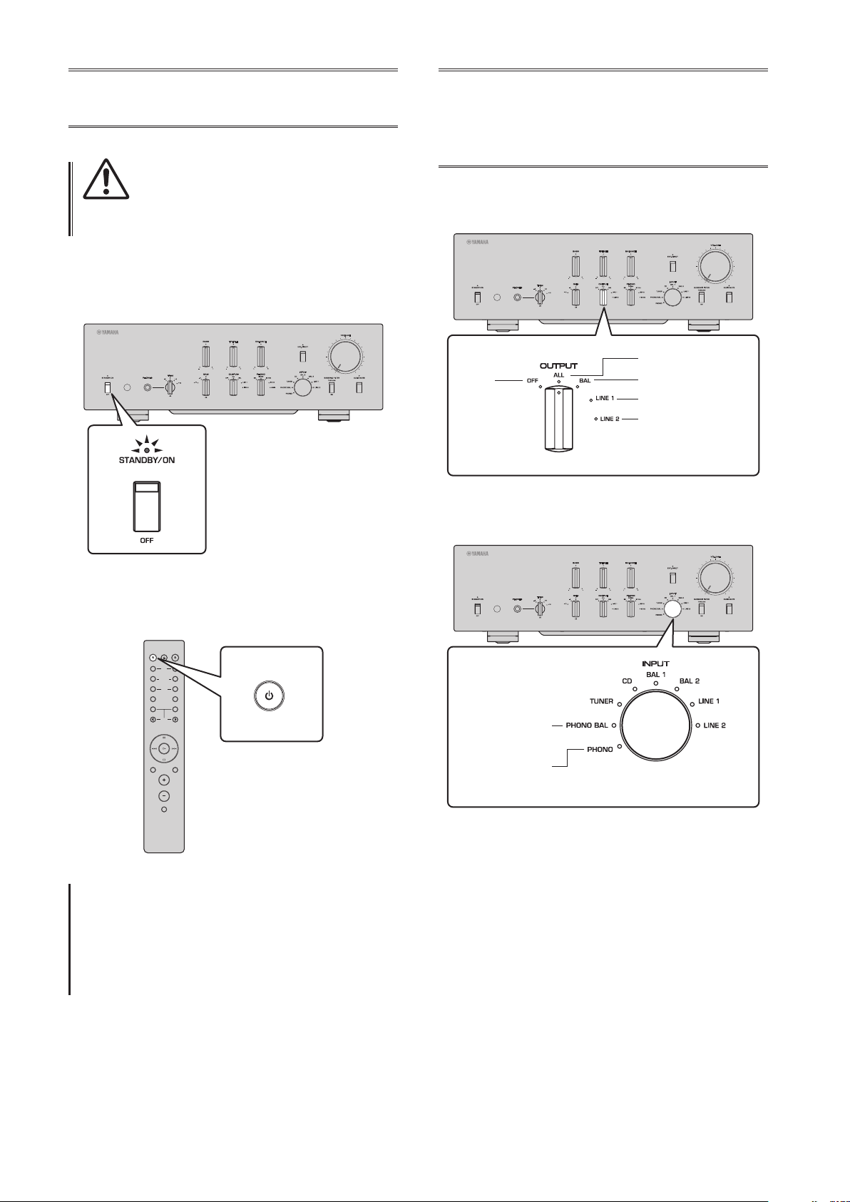
68
Mise sous tension
ATTENTION
Veillez à régler le volume sur le minimum avant de mettre
l’appareil sous tension.
Mettez l’appareil sous tension en réglant son interrupteur
STANDBY/ON/OFF (alimentation) en face avant sur
STANDBY/ON.
Quand l’appareil est en veille, vous pouvez aussi le
mettre sous tension avec la télécommande.
AMPCD
BAL
PHONO
LINE
CD
TUNERBAND
PRESET
SOURCE LAYER
EXT.DIRECT
BAL UNBAL
21
21
OPEN/CLOSE
VOLUME
MUTE
AMP
AVIS
Mettez les appareils sous tension dans l’ordre suivant:
amplicateur de puissance, préamplicateur (cet
appareil), autres composants (comme un lecteur CD et un
syntoniseur).
Inversez cet ordre pour la mise hors tension.
Choix de l’entrée et
de la sortie
Sélectionnez une paire de prises de sortie avec le
sélecteur OUTPUT.
Toutes les prises
Prises BAL uniquement
Prises LINE 1 uniquement
Prises LINE 2 uniquement
Éteint
Sélectionnez la source audio avec le sélecteur INPUT.
Prises PHONO
(symétriques)
Prises PHONO
(asymétriques)
Les témoins correspondants s’allument.

69
Français
Choix du signal reçu aux prises
EXT.IN
Appuyez sur le commutateur EXT. DIRECT. Le témoin
EXT. DIRECT s’allume. La fonction du sélecteur INPUT
est désactivée et le signal de la source audio reçue
aux prises EXT. IN est transmis à une paire de prises
de sortie. Le signal de la source audio reçu aux prises
d’entrée symétrique est restitué aux prises de sortie BAL
symétrique. Le signal de la source audio reçu aux prises
d’entrée LINE est restitué aux prises de sortie LINE 1 et
LINE 2.
Quand vous appuyez à nouveau sur le commutateur EXT.
DIRECT ou tournez le sélecteur INPUT, le signal choisi
avec le sélecteur INPUT est sélectionné comme source
d’entrée. Le témoin EXT. DIRECT s’éteint.
Note
Quand EXT. DIRECT est sélectionné, aucun signal n’est
restitué via les prises LINE 2 OUT (enregistrement) et la
prise PHONES.
Réglage du
paramètre d’entrée
de la platine vinyle
Sélecteur PHONO
Réglez le sélecteur PHONO en fonction du type de
cellule de votre platine vinyle.
Types de cellules prises en charge
Cellule de type MM
Cellule de type MC (environ 300)
Cellule de type MC (environ 100)
Cellule de type MC (environ 30)
Cellule de type MC (environ 10)
ATTENTION
Si votre platine vinyle comporte une cellule de type MM,
veillez à régler le sélecteur PHONO sur la position MM.
Note
Les impédances imprimées sur le sélecteur PHONO sont des
valeurs approximatives. Testez divers réglages d’impédance
pour déterminer quelle option est la plus appropriée.
AVIS
Avant de remplacer la cellule, veillez à mettre cet appareil
hors tension.

70
Filtre subsonique
Activez (ON) le commutateur SUBSONIC FILTER pour
utiliser le ltre subsonique.
Un bras de lecture générant de la résonance ou un disque
vinyle déformé peuvent produire un bruit de très basse
fréquence (bruit subsonique) susceptible d’exercer une
contrainte sur les enceintes et de les endommager. Un
ltre subsonique permet d’éliminer ce type de bruit et
protège les enceintes.
Note
Le ltre subsonique est désactivé quand toute source audio
autre que la platine vinyle (raccordée aux prises PHONO)
est sélectionnée comme source d’entrée, cela même si le
commutateur SUBSONIC FILTER est activé (sur ON).
Réglage du niveau
de volume
Réglez le gain (niveau sonore) avec le sélecteur GAIN de
sorte à pouvoir effectuer des réglages ns de volume.
Gain
Réglez le niveau de volume avec la commande
VOLUME.
Note
Si le son comporte toujours de la distorsion quand vous
réduisez le volume avec la commande VOLUME, le niveau
du signal d’entrée dépasse peut-être le seuil admissible.
Si le signal de la source audio est reçu via les prises
d’entrée symétrique (BAL 1 ou BAL 2), réglez le sélecteur
ATTENUATOR sur ATT. (−6 dB).

71
Français
Réduction momentanée du
niveau de volume
Appuyez sur le commutateur AUDIO MUTE pour
réduire le niveau sonore actuel d’environ 20 dB. Appuyez
à nouveau sur ce commutateur pour rétablir le niveau
sonore initial.
Réglage du timbre
Équilibrez le niveau de volume entre les enceintes gauche
et droite avec la commande BALANCE.
Accentuez ou atténuez le grave et l’aigu respectivement
avec les commandes BASS et TREBLE.
Note
• Quand les commandes BASS et TREBLE sont toutes deux
en position centrale, le signal audio contourne le circuit
de réglage du timbre.
• Les réglages des commandes BASS, TREBLE et BALANCE
n’aectent pas le signal reçu via les prises EXT. IN ni le
signal restitué via les prises LINE 2 OUT (enregistrement).

72
Connexion d’un
casque
Quand vous raccordez un casque à la prise PHONES, les
prises de sortie (BAL, LINE 1 et LINE 2) en face arrière
ne produisent aucun signal.
Utilisez le sélecteur TRIM pour changer le gain de
l’amplicateur de casque an d’équilibrer le niveau du
signal du casque à la prise PHONES et le niveau des
enceintes (et ainsi éviter de brusques sauts de volume).
Note
Quand EXT. DIRECT est sélectionné, aucun signal n’est
restitué à la prise PHONES.

73
Français
Références techniques

74
Caractéristiques générales
Distorsion harmonique totale plus bruit
(JEITA, entrée de 0,5V, 20 Hz à 20 kHz)
BAL 1/BAL 2/TUNER/CD/LINE 1/LINE 2 IN →
BAL/LINE 1/LINE 2 .................0,0100%
PHONO (MC) → LINE 2 OUT (enregistrement)
.................................0,0200%
PHONO (MM) → LINE 2 OUT (enregistrement)
.................................0,0200%
Séparation des voies
(entrée terminée à 1,0 k, 1 kHz/10 kHz, JEITA)
BAL 1/BAL 2/TUNER/CD/LINE 1/LINE 2 IN
............................ 110 dB ou plus
PHONO (MC) ...................80 dB ou plus
PHONO (MM) ..................98 dB ou plus
Séparation de fonction
(réseau IHF-A, entrée terminée à 1,0 k, JEITA)
BAL 1/BAL 2/TUNER/CD/LINE 1/LINE 2 IN
............................ 110 dB ou plus
PHONO (MC) ...................75 dB ou plus
PHONO (MM) ..................95 dB ou plus
Rapport signal/bruit
(réseau IHF-A, entrée terminée à 1,0 k, JEITA)
BAL 1/BAL 2/TUNER/CD/LINE 1/LINE 2 IN
............................ 110 dB ou plus
PHONO (MC 300Ω) ..............80 dB ou plus
PHONO (MM) ..................98 dB ou plus
Bruit résiduel (réseau IHF-A)
BAL/LINE 1/LINE 2 .................... 3 μV
Caractéristiques de contrôle du timbre
Grave
Accentuation/atténuation .......... 30 Hz/±9 dB
Fréquence de transition ............... 350 Hz
Aigu
Accentuation/atténuation ......... 20 kHz/±9 dB
Fréquence de transition ...............3,5 kHz
Tension de sortie nominale/Impédance de sortie
(entrée de 200 mV, 20 Hz à 20 kHz, DHT 0,01%)
BAL (BYPASS) .................. 2 Vrms/150Ω
BAL (ATT. −6dB) ................ 1 Vrms/150Ω
LINE 1/LINE 2 .................. 1 Vrms/150Ω
LINE 2 OUT (enregistrement) ..200 mVrms/1,2 kΩ
Tension de sortie maximale (1 kHz, DHT 0,05%)
BAL ................................ 6 Vrms
LINE 1/LINE 2 ....................... 3 Vrms
LINE 2 OUT (enregistrement) ........... 3 Vrms
Sensibilité et impédance d’entrée
BAL/LINE 1/LINE 2, 1 V
BAL 1/BAL 2 .............. 200 mVrms/52 kΩ
TUNER/CD/LINE 1/LINE 2 IN
....................... 200 mVrms/47 kΩ
EXT.IN .......................1 Vrms/20 kΩ
LINE 2 OUT (enregistrement) (150 mV, 1 kHz)
PHONO (MC 300Ω) ......... 100 μVrms/300Ω
PHONO (MC 100Ω) ......... 100 μVrms/100Ω
PHONO (MC 30Ω) ........... 100 μVrms/30Ω
PHONO (MC 10Ω) ........... 100 μVrms/10Ω
PHONO (MM, type XLR) .....2,5 mVrms/52 kΩ
PHONO (MM, type RCA) .....2,5 mVrms/47 kΩ
Signal d’entrée maximal
LINE 2 OUT (enregistrement) (1 kHz, DHT 0,05%)
BAL (BYPASS) ......................2,8 Vrms
BAL (ATT. −6dB) ....................5,6 Vrms
TUNER/CD/LINE 1/LINE 2 IN .........2,8 Vrms
PHONO (MC) .......................2 mVrms
PHONO (MM) .....................50 mVrms
EXT.IN ............................5,6 Vrms
Réponse en fréquence (JEITA, charge de 22 k)
10 Hz à 100 kHz .....................+0/−3 dB
20 Hz à 20 kHz .................... +0/−0,3 dB

75
Français
Puissance de sortie nominale de la prise casque
(1 kHz, 32, 0,2% DHT)
...........................35 mW + 35 mW
Écart d’égalisation RIAA
MC/MM ............................±0,5 dB
Caractéristiques du ltre subsonique
MC/MM ........................15 Hz/−3 dB
Alimentation
[Modèles pour les États-Unis et le Canada]
.......................... 120 V CA, 60 Hz
[Modèle pour la Chine] ........ 220 V CA, 50 Hz
[Modèle pour la Corée] ........ 220 V CA, 60 Hz
[Modèle pour l’Australie] ....... 240 V CA, 50 Hz
[Modèles pour le Royaume-Uni et l’Europe]
.......................... 230 V CA, 50 Hz
[Modèle pour l’Asie]
... 220–240 V CA, 50 Hz/60 Hz
[Modèles pour l’Amérique Centrale,
l’Amérique du Sud et Taïwan] ... 110 V CA, 60 Hz
Consommation
.................................... 60 W
Consommation en veille
Mode hors tension ..................... 0,1 W
Mode veille ........................... 0,2 W
Dimensions (L × H × P)
....................... 435 × 142 × 451 mm
Poids
.................................. 19,1 kg
* Le contenu de ce mode d’emploi s’applique aux
dernières caractéristiques techniques connues à la
date de publication du manuel. Pour obtenir la version
la plus récente du manuel, accédez au site Web de
Yamaha puis téléchargez le chier du manuel concerné.
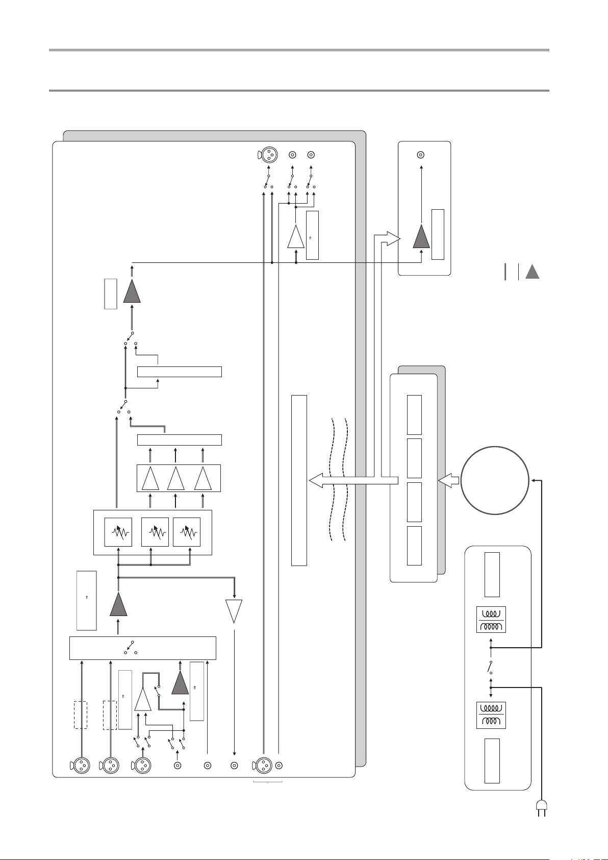
76
Schéma fonctionnel
BAL 2
LINE 2 OUT
(recording)
PHONO
INPUT
INPUT
L channel
R channel
OUTPUT
SELECTOR
BAL
LINE 1
LINE 2
EXT. IN
VOLUME
BUFFER AMP
UNBALANCE
BALANCE
CONVERTER
INDEPENDENT REGULATED POWER SUPPLY (for AUDIO)
SUB TRANSFORMER
TONE CONTROL ON / THROUGH
Relay
BAL 1
LOW IMPEDANCE DRIVE
HEADPHONE AMP.
TONE CONTROL
BAL Normal / UNBAL: 18.6dB
BAL ATT: 12.5dB
TONE CONTROL
POWER RELAY
Relay
Relay
Phase change
(normal/inv.)
Phase change
(normal/inv.)
AMP GAIN: 1.58dB
AMP GAIN: 0.0dB
TUNER /CD
LINE 1/ LINE
2
PHONO
BAL→UNBAL
TREBLE
BASS
MIDDLE
SUBSONIC FILTER
SUBSONIC ON / THROUGH
UNBALANCE BALANCE
CONVERTER
UNBALANCE BALANCE
CONVERTER
BUFFER
AMP PRE
BALANCE UNBALANCE
CONVERTER
CONTROL SPLY
TRANSFORMER
CPU/LOGIC
STANDBY POWER
MOTOR VOL/
RELAY
INDEPENDENT CONSTANT CURRENT POWER SUPPLY
±32V ±81V +99V +12V
PHONES
BALANCE
UNBALANCE
FLOATING BLANCE AMPLIFIER
MM EQ
TOROIDAL
TRANSFORMER
MC BAL

77
Français
Caractéristiques sonores
Réponse en fréquence (commande de timbre)
Response (dB)
Frequency (Hz)
14
12
10
8
6
4
2
0
–2
–4
–6
–8
–10
–12
–14
10 20 30 50 100 200 300 500 1k 2k 3k 5k 10k 20k 30k 50k 100k
+10dB
+8dB
+6dB
+4dB
+2dB
±0dB
–2dB
–4dB
–6dB
–8dB
–10dB
Distorsion harmonique totale (PHONO)
10
5
2
1
0.5
0.2
0.1
0.05
0.02
0.01
0.005
0.002
0.001
0.0005
0.0002
0.0001
100µ 200µ 500µ10µ 20µ 50µ 1m 2m 5m 10m 20m
50m
100m 200m 500m
12
20 Hz 1 kHz 20 kHz
THD + N Ratio (%)
Generator Level (Vrms)

78
Filtre subsonique
Response (dB)
Frequency (Hz)
10
5
0
–5
–10
–15
–20
–25
105203050 100 200 300 500 1k 2k 3k 5k 10k 20k 30k 50k 100
k
THROUGH
ON
Courbe de volume
Volume Level (dB)
Volume control (degree)
0
–20
–40
–60
–80
–100
–110
10
0.00 50.00 100.00 150.00 200.00 250.00
300.00
GAIN selector: –12 dB
GAIN selector: –6 dB
GAIN selector: 0 dB

79
Français
Guide de dépannage
Reportez-vous au tableau suivant si l’appareil ne fonctionne pas comme il devrait. Si les actions correctives suggérées
ci-dessous ne permettent pas de résoudre le problème, ou si le problème rencontré ne gure pas dans le tableau, mettez
l’appareil hors tension, débranchez son cordon d’alimentation et contactez le revendeur ou SAV Yamaha le plus proche.
Anomalies Causes possibles Actions correctives
Voir
page
Impossible de mettre
l’appareil sous tension.
Le cordon d’alimentation n’est
pas raccordé à la prise AC IN du
panneau arrière de l’appareil ou
à une prise secteur.
Branchez fermement le cordon
d’alimentation.
66
L’appareil a été soumis à un choc
électrique puissant (provoqué
par exemple par un orage ou
une décharge d’électricité
statique).
Mettez l’appareil hors tension,
débranchez son cordon d’alimentation
de la prise de courant et attendez
environ 30 secondes avant de le
brancher à nouveau au secteur.
66
Il y a un problème au niveau des
circuits internes de cet appareil.
Débranchez le cordon d’alimentation
de la prise de courant et prenez
contact avec le revendeur ou SAV
agréé Yamaha le plus proche.
66
Aucun son n’est audible.
Les raccordements des câbles
d’entrée ou de sortie ne sont pas
corrects.
Branchez correctement les câbles. Si
le problème persiste, les câbles sont
peut-être défectueux.
60
Aucune source d’entrée
appropriée n’a été sélectionnée.
Sélectionnez la source d’entrée
souhaitée avec le sélecteur INPUT
du panneau avant (ou avec l’une des
touches de sélection d’entrée de la
télécommande).
68
Le réglage du sélecteur OUTPUT
ne correspond pas aux prises de
sortie utilisées.
Sélectionnez une sortie appropriée
avec le sélecteur OUTPUT.
68
Le niveau sonore ne
peut pas être réglé.
EXT. DIRECT est sélectionné
comme source d’entrée.
Réglez le volume sur le composant
raccordé. Vous pouvez aussi raccorder
le composant externe à une paire de
prises d’entrée autre que EXT. IN et
sélectionner ensuite la source d’entrée
en question.
60
68
Le signal est audible sur
une seule voie.
La connexion de l’appareil de
lecture est incorrecte.
Vérifiez que les connexions sont
correctes. Si le problème persiste, les
câbles sont peut-être défectueux.
60

80
Anomalies Causes possibles Actions correctives
Voir
page
Un « ronement » est
audible.
Les raccordements des câbles
d’entrée ou de sortie ne sont pas
corrects.
Branchez correctement les câbles. Si
le problème persiste, les câbles sont
peut-être défectueux.
60
La platine vinyle n’est pas
raccordée à la masse via la borne
GND.
Raccordez la platine vinyle à la borne
GND de cet appareil.
62
Des câbles XLR symétriques et
RCA (Cinch) asymétriques sont
utilisés simultanément entre
deux composants.
N’utilisez pas simultanément des
câbles XLR symétriques et RCA
(Cinch) asymétriques entre deux
composants. Cela génère une boucle
de masse susceptible de causer des
interférences et du bruit.
61
Le signal de lecture du
composant raccordé
aux prises d’entrée
symétrique BAL 1 ou
BAL 2 comporte de la
distorsion.
Le niveau du signal reçu aux
prises d’entrée dépasse la limite
d’entrée admissible.
Si le niveau du signal aux prises
d’entrée XLR symétrique du
composant de lecture raccordé est
deux fois plus élevé que le niveau
aux prises RCA (Cinch) d’entrée
asymétrique, réglez le sélecteur
ATTENUATOR situé sous les prises
d’entrée sur ATT. (−6 dB).
70
Le grave manque de
profondeur quand
vous sélectionnez BAL
1 ou BAL 2 (entrée
symétrique).
La polarité est incorrecte.
Sélectionnez la polarité correcte avec
le sélecteur PHASE.
54
Le volume du disque lu
sur la platine vinyle est
trop bas.
Le réglage du sélecteur PHONO
en face avant est incorrect.
Réglez le sélecteur PHONO sur la
position MM ou MC selon le type
de cellule magnétique de la platine
vinyle.
69
La télécommande ne
fonctionne pas du tout
ou pas normalement.
La télécommande est utilisée
hors de son rayon d’action.
La télécommande doit être utilisée
dans un rayon de 6 m et selon un
angle inférieur à 30 degrés par rapport
à une perpendiculaire à la face avant.
58
Le lumière directe du soleil
ou d’un éclairage (lampe
fluorescente à convertisseur,
stroboscopique, etc.) frappe le
capteur de télécommande sur la
face avant cet appareil.
Changez l’orientation de l’éclairage ou
la position de l’appareil.
58
Les piles sont usées. Remplacez les piles. 58

81
Français
Index
A
Prise AC IN .............................. 66
Amplicateur de puissance, connexion ......... 63
ATTENUATOR, sélecteur ................... 70
AUDIO MUTE, commutateur ................ 71
AUTO POWER STANDBY, commutateur ...... 53
B
BAL 1, prise .............................. 51
BAL 2, prise .............................. 51
BALANCE, commande ..................... 71
BAL, prise ............................... 53
BASS, commande ......................... 71
Borne de masse ........................... 62
Borne SIGNAL GND ...................... 62
C
Capteur de télécommande ................... 58
Casque, connexion ......................... 72
Composant d’enregistrement, connexion ....... 62
Connexion à distance ....................... 65
Connexion asymétrique ..................... 55
Connexion symétrique ...................... 54
E
EXT. DIRECT, commutateur ................ 69
EXT. IN, prise ............................ 63
G
GAIN, sélecteur ........................... 70
I
INPUT, sélecteur .......................... 68
Interrupteur d’alimentation .................. 46
Interrupteur STANDBY/ON/OFF ............. 46
L
LINE 1, prise ............................. 53
LINE 2 IN, prise .......................... 52
LINE 2 OUT (enregistrement), prise ........... 52
LINE 2, prise ............................. 53
M
Mise sous tension ......................... 46
O
OUTPUT, sélecteur ........................ 68
P
PHASE, sélecteur ......................... 54
PHONES, prise ........................... 72
PHONO, prise ............................ 62
PHONO, sélecteur ......................... 69
Platine vinyle, connexion ................... 62
Prise External In .......................... 63
Prise Phono .............................. 62
R
Réglage de l’entrée de la platine vinyle ........ 69
REMOTE, prise ........................... 65
S
SERVICE, prise ........................... 53
SUBSONIC FILTER ....................... 70
SUBSONIC FILTER, commutateur ........... 70
Subwoofer, connexion ...................... 63
T
Témoin d’alimentation ..................... 46
Témoin STANDBY/ON/OFF ................ 46
TREBLE, commande ...................... 71
Trigger, connexion ......................... 64
TRIGGER, prise .......................... 64
TRIM, sélecteur ........................... 72
V
VOLUME, commande ..................... 70

82

83
Français

VAQ1800
Manual Development Group
© 2018 Yamaha Corporation
Published 10/2018 IPEM-A0
Yamaha Global Site
https://www.yamaha.com/
Yamaha Downloads
https://download.yamaha.com/
10-1 Nakazawa-cho, Naka-ku, Hamamatsu, 430-8650 J
apan
U