Loading ...
Loading ...
Loading ...

9
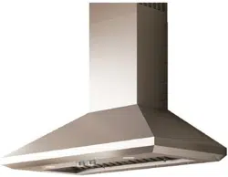
Install range hood
1 Using 2 or more people, hang range hood on 2 mounting
screws through the mounting slots on back of hood.
A
C
B
A. Mounting screws
B. Mounting slots
C. Lower mounting screws
1
2 Mark with a pencil the lower mounting holes location.
3 Uninstall the hood assembly, and drill
3
⁄16” (4.8 mm) pilot
holes at marked locations.
4 Hang the range hood again on 2 upper mounting screws.
5 Level the range hood and tighten upper mounting screws.
6 Install 2 - 5 x 45 mm lower mounting screws and tighten.
Use the optional wall anchors if needed.
Connect vent system
1 Install transition on top of hood (if removed for shipping)
with 2 - 3.5 x 9.5 mm sheet metal screws.
A. Vent transition
B. 3.5 x 9.5 mm screw
For vented installations only:
1 Fit vent system over the exhaust outlet.
2 Measure from the bottom of the air deflector to the
bottom of the hood outlet. Cut the ductwork at the
measured dimension.
Dimension
to measure
Roof outlet
Wall
outlet
3 Seal connection with clamps.
4 Check that back draft dampers work properly.
Electrical connection
I WARNING
ELECTRICAL SHOCK HAZARD.
I WARNING
DISCONNECT POWER BEFORE SERVICING.
REPLACE ALL PARTS AND PANELS BEFORE OPERATING.
FAILURE TO DO SO CAN RESULT IN DEATH OR
ELECTRICAL SHOCK.
1 Disconnect power.
2 Remove terminal box cover.
3 Remove the knockout in the terminal box cover and install
a UL listed or CSA approved
1
⁄2” strain relief.
B A
C
A. Knockout
B. Junction box cover
C. Junction box cover screws
4 Run home power supply cable through strain relief, into
terminal box.
A
B
C
D
E
F
A.White wires
B. Black wires
C. UL listed wire connectors
D. Green, Bare or Yellow/Green wires
E. Home power supply
F. UL listed or CSA approved ½” strain
relief
5 Use UL listed wire connectors and connect black wires
(C) together.
6 Use UL listed wire connectors and connect white wires (E)
together.
I WARNING
ELECTRICAL SHOCK HAZARD.
I WARNING
ELECTRICALLY GROUND BLOWER.
CONNECT GROUND WIRE TO GREEN AND YELLOW
GROUND WIRE IN TERMINAL BOX. FAILURE TO DO SO CAN
RESULT IN DEATH OR ELECTRICAL SHOCK.
7 Connect green (or bare) ground wire from home power
supply to yellow-green ground wire (F) in terminal box
using UL listed wire connectors.
8 Tighten strain relief screw.
9 Install terminal box cover.
10 Check that all light bulbs are secure in their sockets.
11 Reconnect power.
Loading ...
Loading ...
Loading ...