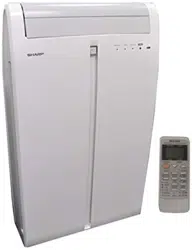
AF-S155NX
N
Please read ALL instructions before installing. Two people are
recommended to install this product. If a new electrical outlet
is required, have the outlet installed by a qualified electrician
before installing unit. See#5 in Preliminary Instructions
following.
Preliminary instructions
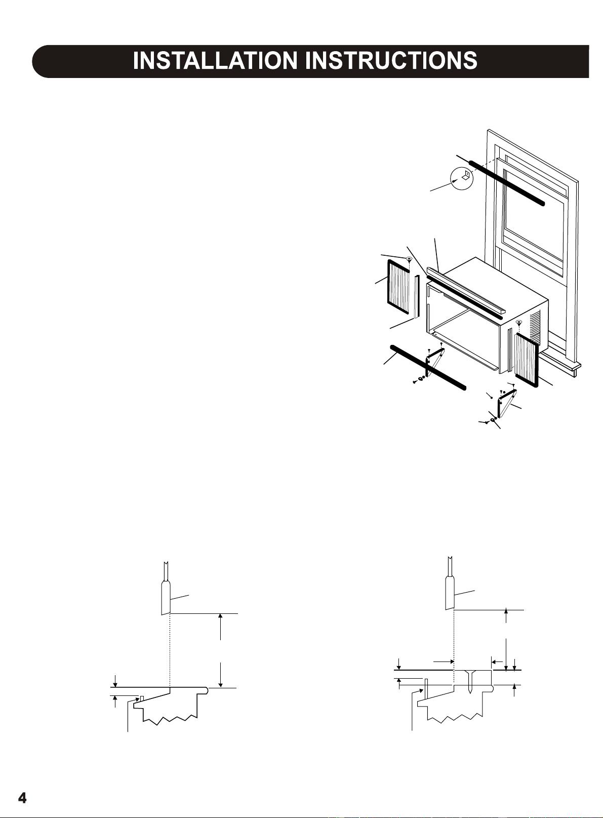
Do the following before starting to install unit. See illustrations
below.
with this air conditioner are made to install in a wooden
Check dimensions of your unit to determine model type:
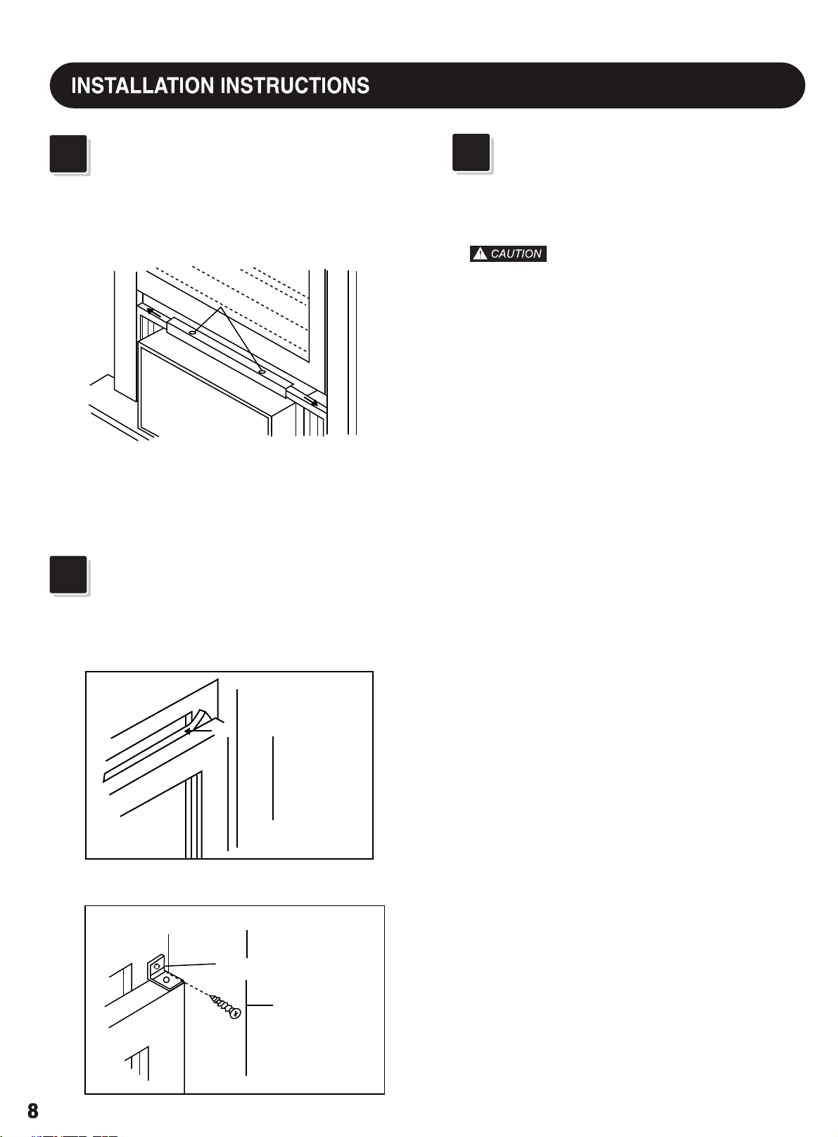
1. Check window opening size - the mounting parts furnished
sill double-hung window. The standard parts are for
window dimensions listed above. Open sash to a minimum
of 19"(483mm). (FIG. 1)
2. Check condition of window - all wood parts of window
must be in good shape and able to firmly hold the needed
screws.If not, make repairs before installing unit.
3. Check your storm windows - if your storm window
frame does not allow the clearance required, correct by
adding a piece of wood as shown in FIG.2, or by removing
storm window while room air conditioner is being installed.
(continued)
Unit Height:
Unit Width:
Min. Window Opening:
Min. Window Width:
Max. Window Width:
17.5/8"
23
1
/
2
"
18
1
/
2
"
26
1
/
2
"
40
1
/
2
"
FIG. 1
FIG. 2
SASH
19" MIN
1/2" MIN
STORM WINDOW FRAME OR
OTHER OBSTRUCTION
SASH
1/2" MIN
19" MIN
STORM WINDOW FRAME OR
OTHER OBSTRUCTION
1 1/2" MIN
BOARD THICKNESS AS
REQUIRED, ALONG
ENTIRE STOOL, FASTEN
WITH TWO NAILS OR
SCREWS.
SEAL-BOTTOM RAIL TO UNIT
SIDE RETAINER
FRAME
ASSEMBLY
(LEFT)
WASHER HEAD
LOCKING SCREW
FOAM GASKET
TOP ANGLE
FRAME
ASSEMBLY
(LEFT)
SAFETY LOCK AND
3/4" LONG HEX HEAD
SCREW
1/2" LONG
SCREWS AND
LOCKNUTS
LOCKNUT
3/4" LONG
FLAT HEAD
BOLT
WINDOW SUPPORT
BRACKET
WINDOW SASH SEAL
SILLANGLE
BRACKET
4. CHECK FOR ANYTHING THAT COULD BLOCK
AIRFLOW - check area outside of window for things
such as shrubs, trees, or awnings. Inside, be sure
furniture, drapes, or blinds will not stop proper air flow.
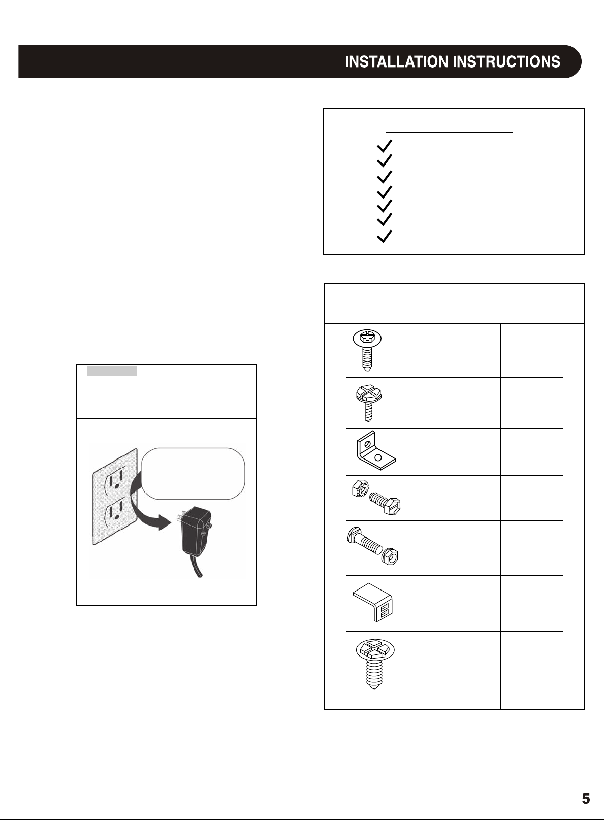
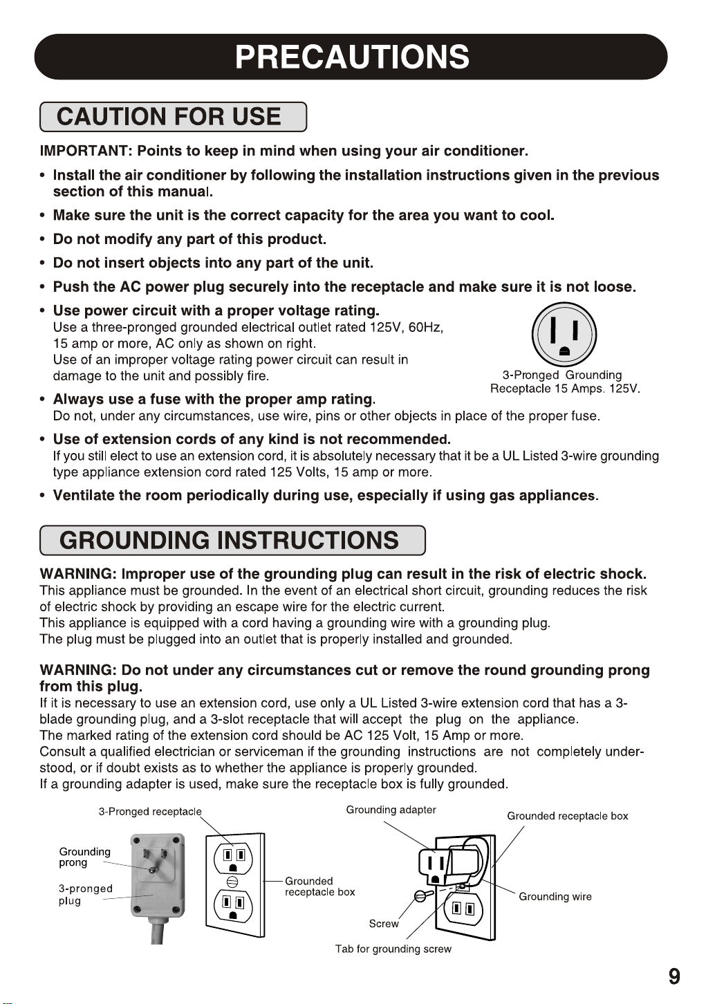
5. Check the available electrical service - power supply must
be the same as that shown on the unit serial nameplate.
Power cord is 48"long. Be sure you have an outlet near.
All models have a 3-prong service plug to provide proper
service and safe positive grouding. Do not change plug in
any way. Do not use an adapter plug. If your present wall
outlet does not match your plug, call a qualified electrician
to make the needed change.
a large flat blade screwdriver
tape measure
adjustable wrench or pliers
pencil
Level
Socket wrenches
Phillips screwdriver
Tools Required
Hardware (in plastic bag)
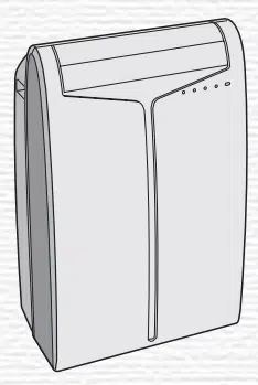
6. Carefully unpack air conditioner - remove all packing
material. Protect floor or carpet from damage. Two
people should be used to move and install unit.
Avoid fire hazard or electric
shock. Do not use an extension cord or an
adaptor plug. Do not remove any prong from
the power cord.
WARNING
Grounding type wall
receptacle
Do not, under any
circumustances, cut,
remove, or bypass the
grounding prong.
Power supply cord
with 3-prong grounding
plug and current
detection device
Washer Head
Locking Screw
For window panels
3/4" Long Hex-
Head Screw
3
2
Qty.
Safety Lock
1/2" Long Screw
and locknut
3/4" Long Flat
Head Bolt and
Locknut
Sill Angle Bracket
1
4 ea.
2 ea.
2
10
Long hex-head
locking screw for
top angle, side
retainer 5/16"
Long
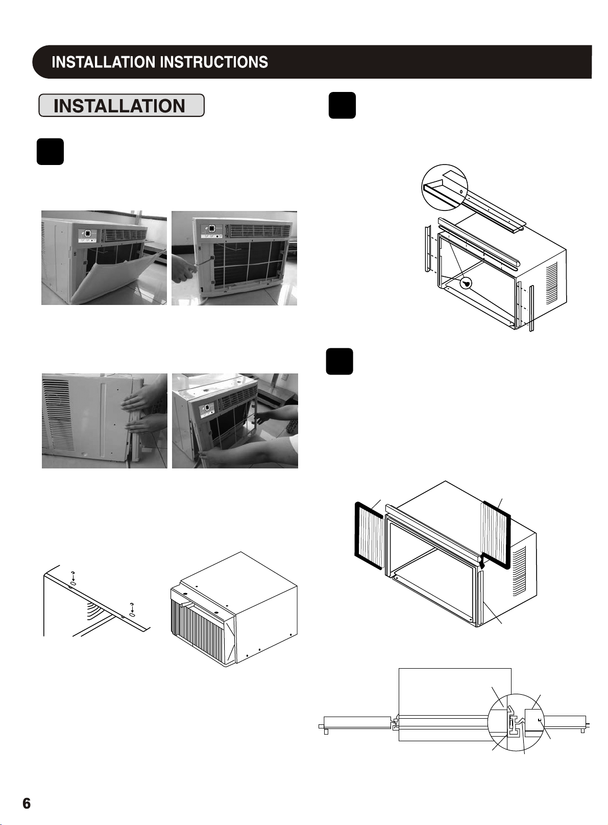
Remove Chassis
Install Top Angle
and Side Bracket
1
2
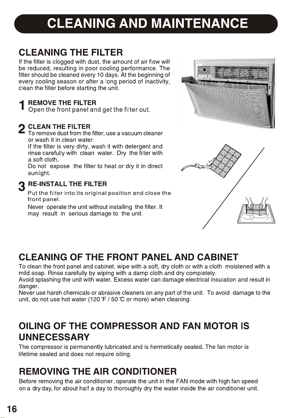
1. Pull down front panel and remove filter. (See FIG. 1).
2. Lift front upwards and place to one side.
1. Attach foam gasket to top angle above holes as
shown in FIG. 6.
3. Locate the four front screws and remove. These screws will
be needed to re-install the front later. (See FIG.2)
4. Pry away front from cabinet sides as per photo (see FIG.3)
5. Gently lift front off unit and place to one side (See FIG.4).
2. Install top
angle and
side retainers
to cabinet as
shown in FIG. 6.
FIG. 6
6. Remove shipping crews from top of unit and also on the side
by the base if installed.
7. Hold the cabinet while pulling on the base handle, and care-
fully remove the unit.
8. Add two foam inserts to holes in top of cabinet where
shipping screws were removed from.
Assemble Window
Filler Panels
1. Place cabinet on floor, a bench, or a table.
2. Slide "I" section of window filler panel into side retainer
on the side of the cabinet (see Figures 7-8). Do both
sides.
FIG. 7
3
PLASTIC
FRAME
WINDOW FILLER
PANEL
SIDE
RETAINER
FIG. 8
AIR CONDITIONER
CABINET
TOP
VIEW
PLASTIC
FRAME
"I" SECTION
WINDOW
FILLER
PANEL
LOCKING
SCREW
HOLE
FIG. 3
FIG. 4
FIG. 1
FIG. 2
3. Insert top and bottom legs of window filler panel frame
into channel in the to angle and bottom rail. Do both
sides.
4. Insert washer head locking screws (2) into holes in
top leg of filler panel frame (see Step 6). Do not totally
tighten. Allow leg to slide freely. Screws will be
tightened after Section 6.
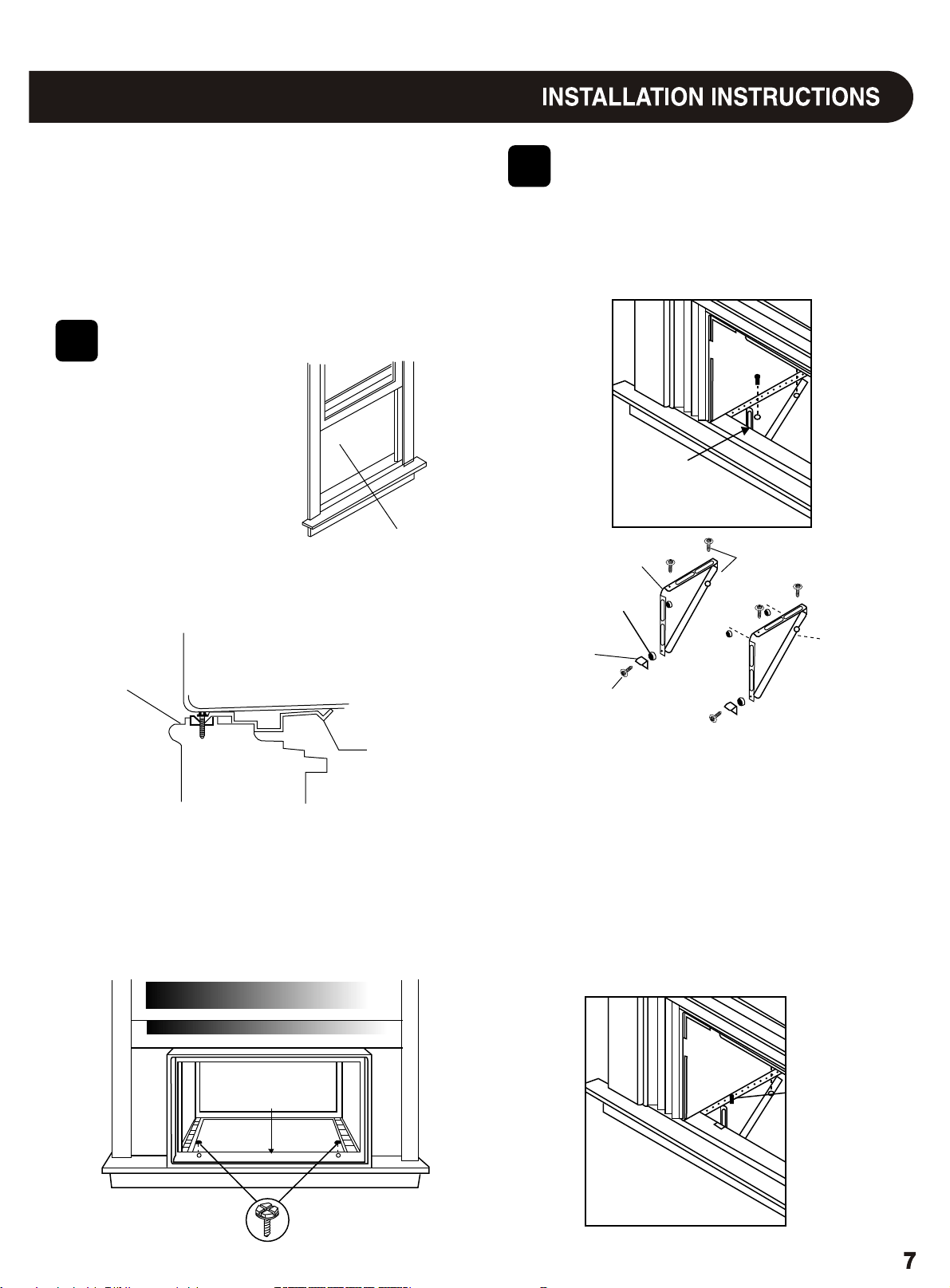
Install Support
5
Bracket
1. Hold each support bracket flush against outside of sill,
and tight to bottom of cabinet as shown below. Mark
brackets at top level of sill, and remove.
Place Cabinet in
4
Window
1. Open window and mark
center of window stool.
2. Place cabinet in window with bottom stool angle firmly
scated over window stool as shown. Bring window
down temporarily behind top angle to hold cabinet in
place.
STOOL
STOOL
ANGLE
LEFT
LOCKNUT
SILL ANGLE
BRACKET
FLAT HEAD BOLT
2 EACH REQ'D FOR EACH
SUPPORT BRACKET
MARK
1/2" LONG SCREWS
AND LOCKNUTS
RIGHT
3. Shift cabinet left or right as needed to line up center of
cabinet on center line marked on stool.
4. Fasten cabinet to window stool with 2 screws into
holes.(You may wish to pre-drill pilot holes.)
5. Add bottom rail seal over screws to window stool.
2. Asscmble sill angle bracket to support brackets at the
marked position, as shown. Hand tighten, but allow
for any changes later.
3. Install support brackets (with sill angle brackets
attached) to correct hole in bottom of cabinet as shown.
4. Tighten all 6 bolts securely.
1/2" long screws
and locknuts
Bottom
Rail Seal
3/4" long HEX-
HEAD SCREW
Extend Window Filler
Panels
1. Carefully raise window to expose filler panel locking
1. Lift air conditioner and carefully slide into cabinet
3. Be sure chassis is firmly seated towards rear of cabinet.
4. Installation of front is the reverse of removal outlined
2.
leaving 6" protruding.
in Section 1.
DO not push on controls OR finned coils.
screws. Loosen screws so filler panels slide easily.
2. Extend panels to fill window opening completely.
3. Close window behind top angle.
Tighten locking screws on top.
1. Trim sash seal to fit window width. Insert into space
between upper and lower sashes.
2. Attach right angle safety lock as shown.
LOCKING SCREWS
WINDOW SASH SEAL
SAFETY LOCK
3/4" long hex-
head screw
6
Install Chassis into
Cabinet and Install
Front to Unit
8
Install Window Lock
and Sash Seal
7
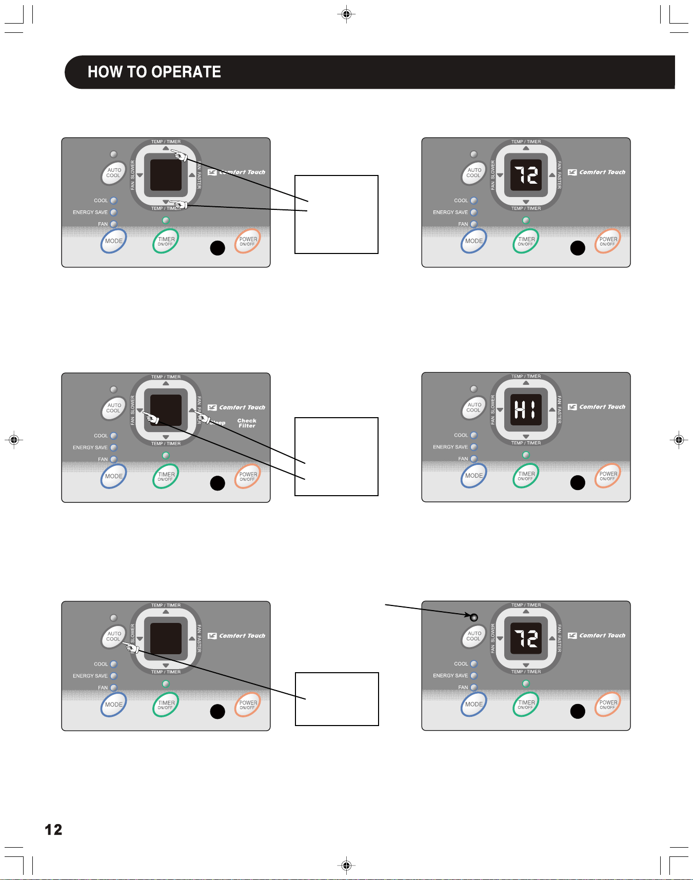
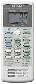
TO CHANGE TEMPERATURE
TO ADJUST FAN SPEEDS:
TO USE AUTO COOL FEATURE:
YOU WILL SEE :
YOU WILL SEE:
SETTING:
YOU WILL SEE:
Note:
Tap or hold either up ( ) or down ( ) button until the desired temperature is seen on the display. This temperature will be automati-
Note:
Fan speed starts at High Speed and adjusts to a slower speed as the room temperature dictates, For example if the room doesn't
get too warm, it will stay at the slowest speed. If the room temperature rises quickly,such as a door being opened, it will automatically go
to the highest speed. The fan speeds will re-adjust back to the slowest speed as the room returns to the original set temperature.
cally maintained anywhere between 60
o
F (16
o
C) and 90
o
F (32
o
C) for cooling mode. If you want the display to read the actual room temperature.
Press the Fan Faster button will increase the fan speed from Low (LO), to Medium (ME), to High (HI). The digital display will indicate
your chosen speed. Press the Fan Slower button will decrease the fan speed from High (HI), to Medium (ME), to Low (LO).The digital display will
indicate your chosen speed.After 5 seconds the display will revert back to the set temperature.
See "To Operate on Fan " section on Page 13.
▲
▲
LIGHT On
DO THIS:
PRESS TO
PRESS TO
RAISE
LOWER
DO THIS:
PRESS
FASTER
TO SELECT:
SLOWER
DO THIS:
PRESS
AUTO COOL
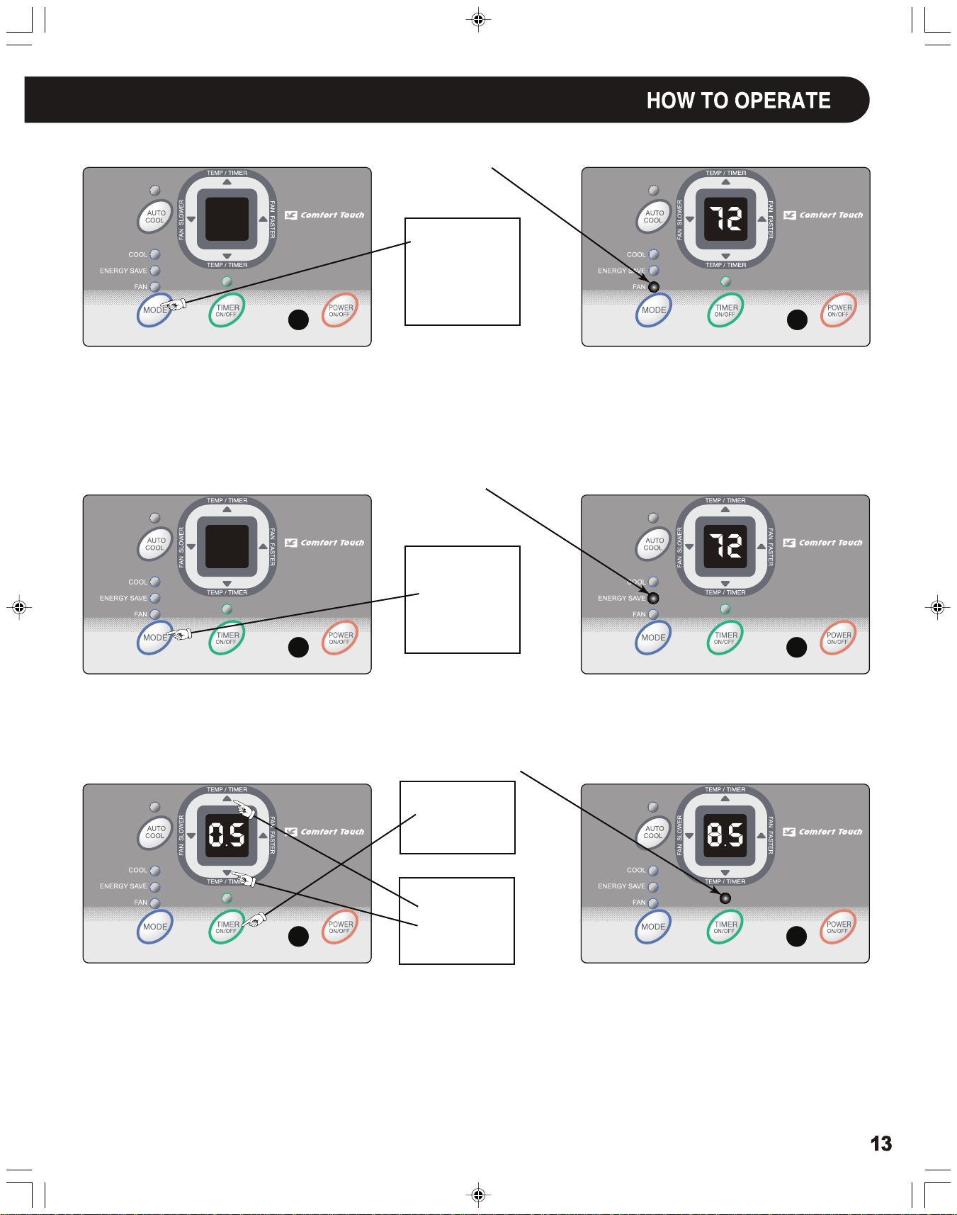
TO OPERATE ON FAN:
TO USE THE
ENERGY SAVE FEATURE:
TIMER: TIMER ON/OFF
YOU WILL SEE:
YOU WILL SEE:
YOU WILL SEE HOW MUCH TIME IS CHOSEN:
DO THIS:
LIGHT On
LIGHT On
LIGHT On
PRESS
MODE BUTTON
CHOOSE
FAN
DO THIS:
PRESS
MODE BUTTON
CHOOSE
ENERGY SAVE
FIRST
DO THIS:
PRESS
TIMER BUTTON
THEN
DO THIS:
PRESS
TEMP/TIMER
SET BUTTON
Note: Use this function only when cooling is not desired, such as for room air circulation or to exhaust stale air. (Remember to open the
Note:
In this mode, the fan will continue to run for another 3 minutes after the compressor shuts off. The fan then cycles on for 2 minutes
Note 1:
For Timer Off, the unit must be in the On position.
Note 2:
For Timer On, the unit must be in the Off position.
To adjust timer setting, tap or hold the UP arrow ( ) or the DOWN arrow ( ) to change delay timer at 0.5 hour increments, up to 10
hours, then at 1 hour increments up to 24 hours. The control will count down the time remaining until start (8, 7.5, 7, etc.). The Timer On
mode automatically selects cooling with maximum Fan Speed. The temperature maintained will be the same as previously set. To change the
set temperature, press "MODE" then Up or Down arrows until the desired temperature is indicated on the display. After 5 seconds, the con-
trol will automatically change the display back to the hours remaining until the unit will start/stop. Turning the unit "On" or "Off" at any time
will cancel the Timer On/Off function. The Timer On/Off Feature will work until the unit either starts or stops. Once that happens the above
steps have to be repeated again.
at 10 minute intervals until the room temperature is above the set temperature, at which time the the cooling system turns back on.
vent during this function, but keep it closed during cooling for maximum cooling efficiency.) You can choose any fan speed you prefer. (Exc-
ept "Auto Cool").
During this function, the display will show the actual room temperature, not the set temperature as in the cooling mode.
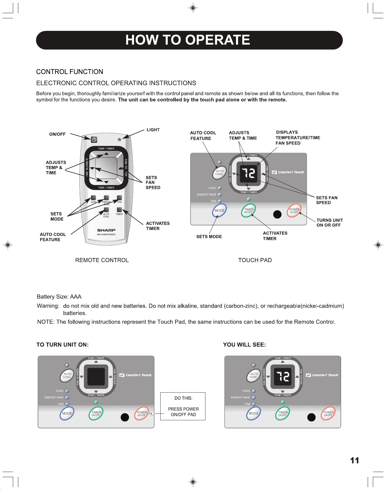
▲
▲
DO THIS:
PRESS POWER
ON/OFF
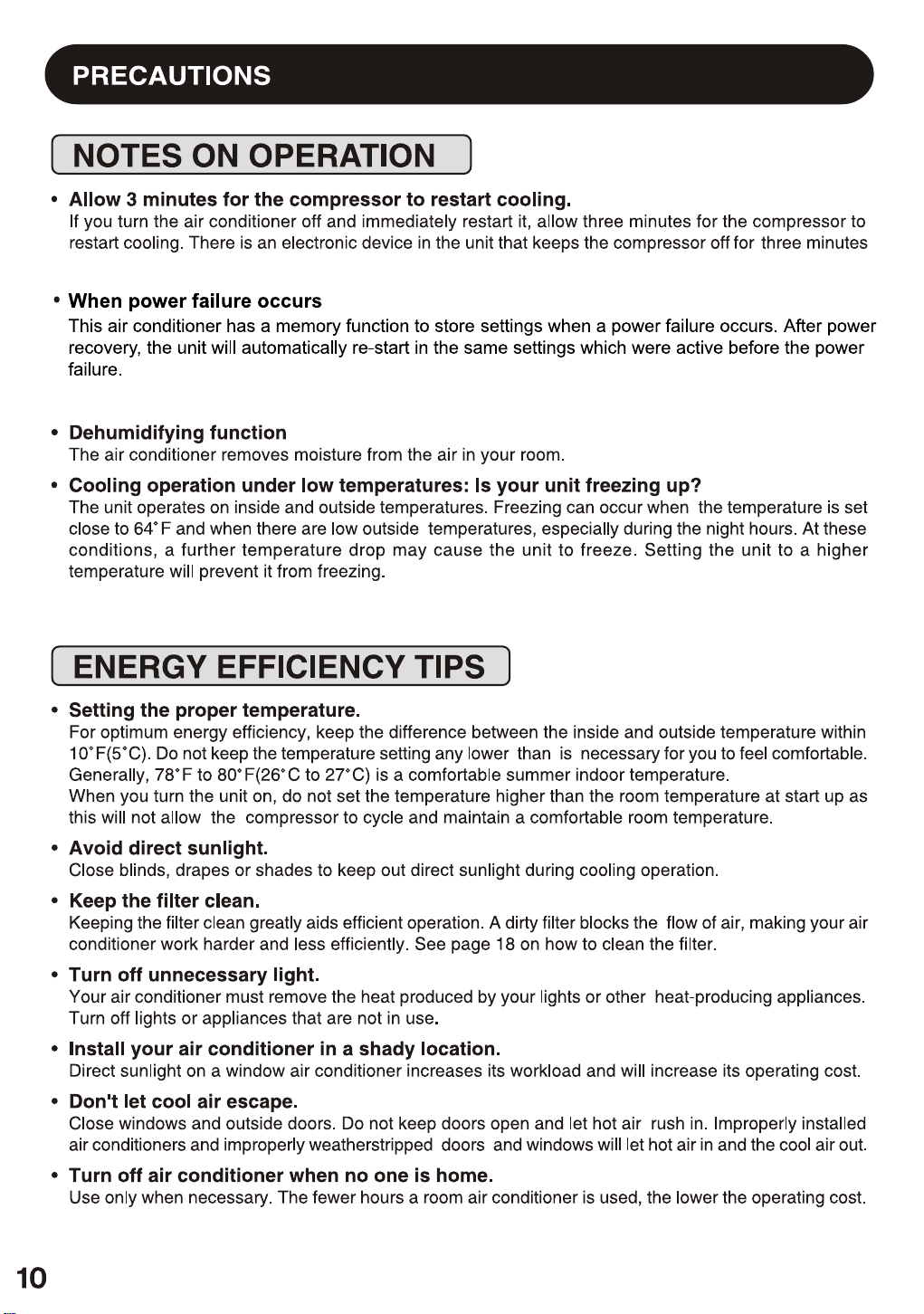
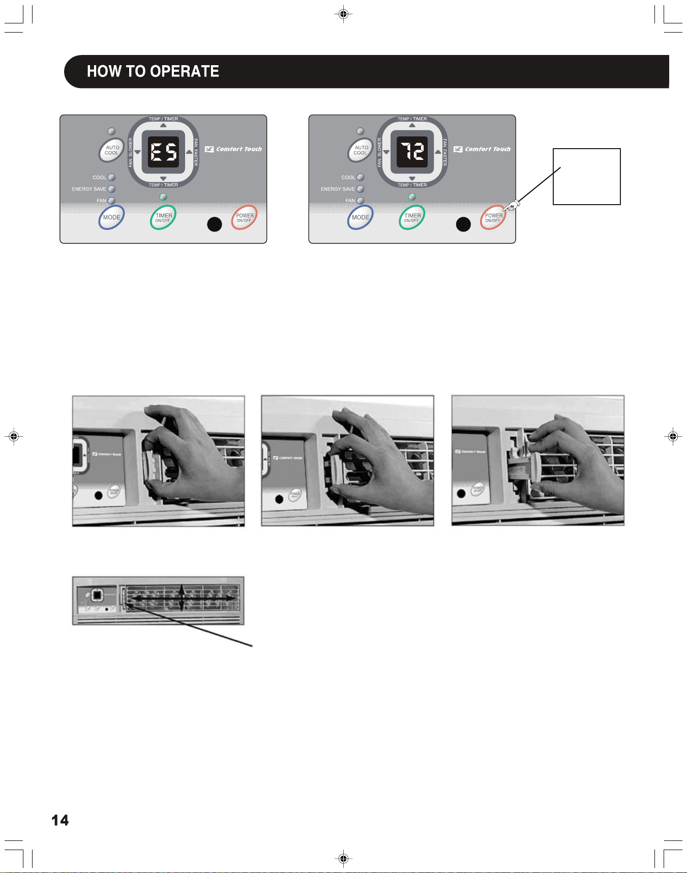
Fresh Air Vent Control
The Fresh Air Vent allows the air conditioner to:
1. Recirculate inside air - Vent Closed (see Fig. 1)
2. Draw fresh air into the room - Vent Open (see Fig. 2)
3. Exchange air from the room and draws fresh air into the room - Vent and Exhaust
Open (see Fig. 3)
Fig. 1 (OFF)
Fig. 2 (FRESH AIR)
Fig. 3 (VENT)
AUGER WHEEL
The louvers will allow you to direct the air flow Up or Down and Left or Right throughout
the room as needed.Rotate the Auger Wheel Up or Down until the desired direction is
obtained.
(4-WAY)
FAULT CODES
If the display reads "ES" or "AS", a sensor has failed.
Contact your Authorized SHARP Service Center.
TO TURN UNIT OFF:


66129901273