
Loading ...
Continued on Next Page
SB-GM-ESC(ESV)/10W1v2 INSTR_SKU# 011303
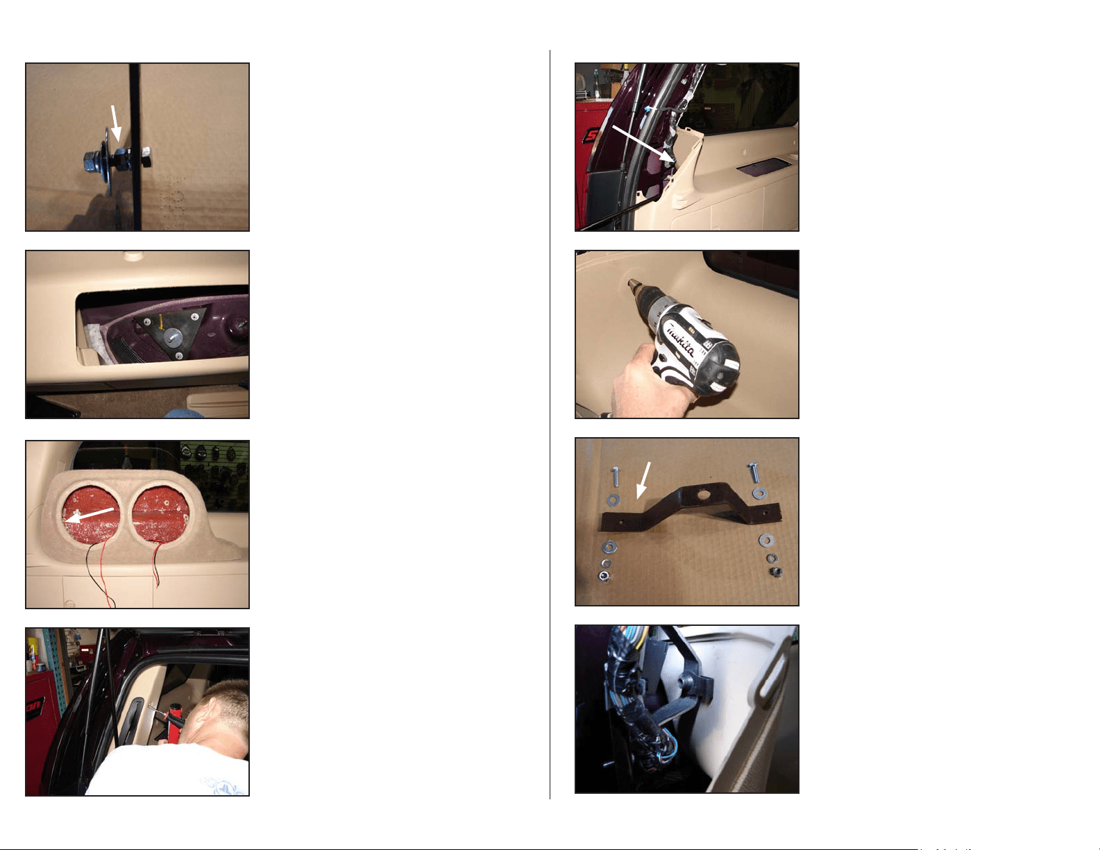
S T E P 7
Remove the upper rear quarter window trim molding.
S T E P 6
Remove the two woofers from the Stealthbox® and, set it
into place, with the extension going into the previous pocket
location.
Inside the Stealthbox®, where the arrow points, use a small
marker to mark the interior panel where the hole in the
enclosure wall lies.
Remove the Stealthbox®
S T E P 5
Install the Triangular Plate as shown, tighten down the
fasteners that secure the Triangular Plate, leave only the large
Flat washer on top of the Hex nut, Split Lock Washer and
3/8-16 x 1-3/4” Hex Head Bolt. The remaining Flat Washer,
Split Lock Washer and Hex Nut will be installed inside the
enclosure.
S T E P 4
This is a side view of the Bracket shown in STEP 3 with the
included hardware shown for illustration purposes. Install
the 3/8-16 x 1-3/4” Hex Head Bolt through the Triangular
Plate as shown, tighten the Hex Nut that the arrow points
towards. The hardware shown to the left of the 3/8 x 2”
Fender Washer will be inside the Stealthbox® once the
installation is complete.
Page 2 • JL Audio, Inc 2009
S T E P 9
Drill the mark made in STEP 6, enlarge the hole to 1/2 inch.
****CAUTION****
Before drilling, always make sure that you are not
going to be drilling into any gas lines, brake lines,
tires, transmission lines, electrical wiring, exhaust
systems or anything else that might cause a
reduction in your weekly pay.
Always wear eye protection when drilling!
S T E P 1 1
Bolt the bottom hole of the Custom Bracket to the rear
pillar through the hole where the wiring harness had been
secured (see STEP 8). Slide the supplied 3/8-16 Speed Nut
onto the Custom Bracket as shown, align the hole in the
Custom Bracket with the hole in the rear quarter trim panel.
S T E P 1 0
The 1/4” hardware will be installed in the order as shown as
the custom bracket is installed in the vehicle.
NOTE: The arrow points to the upper end of the bracket.
S T E P 8
The upper mount for the lift arm for the tailgate must be
disconnected as shown in order to remove the trim panel.
The wiring harness that runs along the rear pillar has a white
plastic plug (see arrow) that pushes through a hole in the
pillar to locate it. Pull the plug as this hole will be used to
secure the lower end of the Custom Bracket shown in
STEP 10.
Loading ...