GE GE50M6A SmartWater Electric Water Heater
Product's Documents
Below are documents related to this product, you can read online or download:
- User Manual - (English) Read Online | Download pdf
The location chosen for the water heater must take into consideration the following:
This water heater must be installed in accordance with these instructions, local codes, utility codes, utility company requirements or, in the absence of local codes, the latest edition of the National Electrical Code. It is available from some local libraries or can be purchased from the National Fire Protection Association, Batterymarch park, Quincy, MA 02269 as booklet ANSI/NFPA 70.
Locate the water heater in a clean dry area as near as practical to the area of greatest heated water demand. Long uninsulated hot water lines can waste energy and water.
Place the water heater in such a manner that the thermostat and element access panels can be removed to permit inspection and servicing such as removal of elements or checking controls.
The water heater and water lines should be protected from freezing temperatures. Do not install the water heater in outdoor, unprotected areas.
CAUTION: The water heater should not be located in an area where leakage of the tank or connections will result in damage to the area adjacent to it or to lower floors of the structure. Where such areas cannot be avoided, it is recommended that a suitable catch pan, adequately drained, be installed under the water heater.
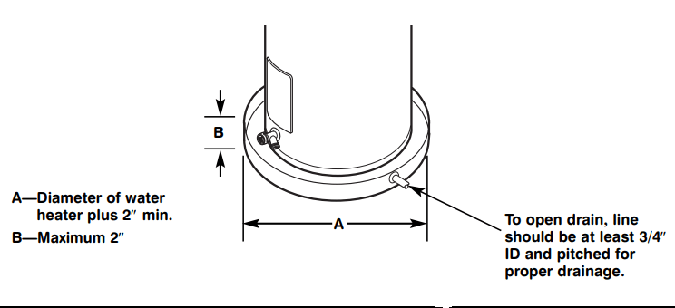
NOTICE: Auxiliary catch pan MUST conform to local codes. Catch Pan Kits are available from the store where the water heater was purchased, or any water heater distributor.
Inspect the water heater for possible damage. Check the markings on the rating plate of the water heater to be certain the power supply corresponds to the water heater requirements.
Determine if a check valve exists in the inlet water line. It may have been installed in the cold water line as a separate back flow preventer, or it may be part of a pressure reducing valve, water meter or water softener. A check valve located in the cold water inlet line can cause what is referred to as a “closed water system”. A cold water inlet line with no check valve or back flow prevention device is referred to as an “open” water system.
As water is heated, it expands in volume and creates an increase in the pressure within the water system. This action is referred to as “thermal expansion”. In an “open” water system, expanding water which exceeds the capacity of the water heater flows back into the city main where the pressure is easily dissipated.
A “closed water system”, however, prevents the expanding water from flowing back into the main supply line, and the result of “thermal expansion” can create a rapid and dangerous pressure increase in the water heater and system piping. This rapid pressure increase can quickly reach the safety setting of the relief valve, causing it to operate during each heating cycle. Thermal expansion, and the resulting rapid and repeated expansion and contraction of components in the water heater and piping system can cause premature failure of the relief valve, and possibly the heater itself. Replacing the relief valve will not correct the problem!
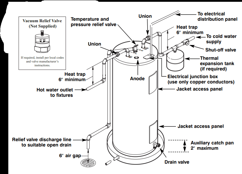
The suggested method of controlling thermal expansion is to install an expansion tank in the cold water line between the water heater and the check valve (refer to the illustration below). The expansion tank is designed with an air cushion built in that compresses as the system pressure increases, thereby relieving the over pressure condition and eliminating the repeated operation of the relief valve. Other methods of controlling thermal expansion are also available. Contact your installing contractor, water supplier or plumbing inspector for additional information regarding this subject.
NOTICE: Do not apply heat to the HOT or COLD water connections. If sweat connections are used, sweat tubing to adapter before fitting adapter to the water connections on heater. Any heat applied to the water supply fittings will permanently damage the dip tube and/or heat traps.
Refer to the illustration below for suggested typical installation. The installation of unions or flexible copper connectors is recommended on the hot and cold water connections so that the water heater may be easily disconnected for servicing if necessary. The HOT and COLD water connections are clearly marked and are 3/4″ NPT on all models. Install a shut-off valve in the cold water line near the water heater.
A new combination temperature and pressure relief valve, complying with the Standard for Relief Valves and Automatic Gas Shut-Off Devices for Hot Water Supply Systems, ANSI Z21.22, is supplied and must remain installed in the opening provided and marked for the purpose on the water heater. No valve of any type should be installed between the relief valve and the tank. Local codes shall govern the installation of relief valves.
WARNING: The pressure rating of the relief valve must not exceed 150 PSI, the maximum working pressure of the water heater as marked on the rating plate.
The BTUH rating of the relief valve must not be less than the input rating of the water heater as indicated on the rating label located on the front of the heater (1 watt=3.412 BTUH).
Connect the outlet of the relief valve to a suitable open drain so that the discharge water cannot contact live electrical parts or persons and to eliminate potential water damage.
Piping used should be of a type approved for hot water distribution. The discharge line must be no smaller than the outlet of the valve and must pitch downward from the valve to allow complete drainage (by gravity) of the relief valve and discharge line. The end of the discharge line should not be threaded or concealed and should be protected from freezing. No valve of any type, restriction or reducer coupling should be installed in the discharge line
WARNING: The tank must be full of water before heater is turned on. The water heater warranty does not cover damage or failure resulting from operation with an empty or partially empty tank. (Refer to the Certificate of Limited Warranty for complete terms and conditions.)
Make certain the drain valve is completely closed.
Open the shut-off valve in the cold water supply line.
Open each hot water faucet slowly to allow the air to vent from the water heater and piping.
A steady flow of water from the hot water faucet(s) indicates a full water heater.
Condensation can form on the tank when it is first filled with water. Condensation might also occur with a heavy water draw and very cold inlet water temperature.
This condition is not unusual, and will disappear after the water becomes heated. If, however, the condensation continues, examine the piping and fittings for possible leaks.
Additional information on this subject may be found at "rheem" under “Library”. Scroll down to the Technical Service Bulletins 1300 Series Section and choose Bulletin #1303.
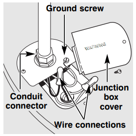
Water heater junction box.
CAUTION: The presence of water in the piping and water heater does not provide sufficient conduction for a ground. Non-metallic piping, dielectric unions, flexible connectors etc. can cause the water heater to be electrically isolated.
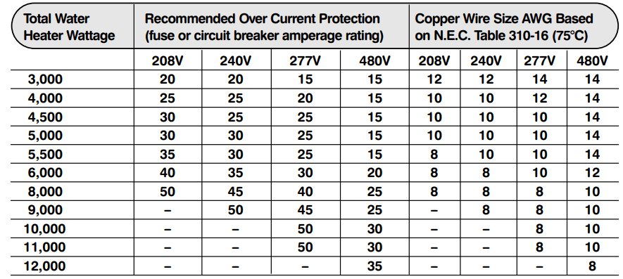
A separate branch circuit with copper conductors, overcurrent protective device and suitable disconnecting means must be provided by a qualified electrician.
All wiring must conform to local codes or latest edition of National Electrical Code ANSI/NFPA 70.
The water heater is completely wired to the junction box inside jacket at the top front of the water heater. An opening for 1/2″ or 3/4″ electrical fitting is provided for field wiring connections.
The voltage requirements and wattage load for the water heater are specified on the rating plate on the front of the water heater.
The branch circuit wiring should include either:
NOTICE: This guide recommends minimum branch circuit sizing and wire size based on National Electric Code. Refer to wiring diagrams in this manual for field wiring connections.
WARNING: If local codes require external application of insulation blanket kits the manufacturer’s instructions included with the kit must be carefully followed.
Insulation blankets, available to the general public, for external use on electric water heaters are not necessary. The purpose of an insulation blanket is to reduce the standby heat loss encountered with storage tank heaters. This water heater meets or exceeds the National Appliance Energy Conservation Act standards with respect to insulation and standby loss requirements making an insulation blanket unnecessary.
The manufacturer’s warranty does not cover any damage or defect caused by installation, attachment or use of any type of energy saving or other unapproved devices (other than those authorized by the manufacturer) into, onto or in conjunction with the water heater. The use of unauthorized energy saving devices may shorten the life of the water heater and may endanger life and property.
The manufacturer disclaims any responsibility for such loss or injury resulting from the use of such unauthorized devices.
CAUTION: If local codes require the application of an external insulation blanket to this water heater, pay careful attention to the following so as not to restrict the proper function and operation of the water heater:

Typical vertical piping arrangement
For increased energy efficiency, some water heaters have been supplied with two 24” sections of pipe insulation.
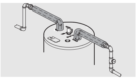
Typical horizontal piping arrangement
Please install the insulation, according to the illustrations above, that best meets your requirements.
CAUTION: Ensure the T&P Valve opening is not obstructed by the insulation.
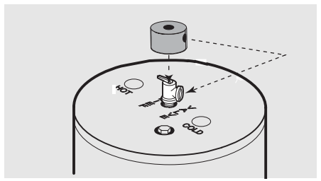
Typical top connection arrangement
For increased energy efficiency, some water heaters have been supplied with a 2-3/8” section of pipe insulation.
Please install the insulation, according to the illustrations above, that best meets your requirements.
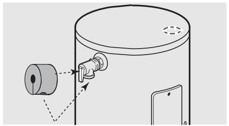
Typical side connection arrangement
Slip the insulation cover over the T&P Valve through the center hole and align the hole in the side with the opening of the T&P Valve.
For increased energy efficiency, some water heaters have been supplied with factory installed heat traps in the hot outlet line and cold water inlet line.
NOTICE: Do not apply heat to the hot or cold water connections. If sweat connections are used, sweat tubing to adapter before fitting adapter to the water connections on heater. Any heat applied to the water supply fittings will permanently damage the dip tube and/or heat traps.
CAUTION: Hydrogen gas can be produced in a hot water system served by this water heater that has not been used for a long period of time (generally two weeks or more). HYDROGEN GAS IS EXTREMELY FLAMMABLE!! To dissipate such gas and to reduce risk of injury, it is recommended that the hot water faucet be opened for several minutes at the kitchen sink before using any electrical appliance connected to the hot water system. If hydrogen is present, there will be an unusual sound such as air escaping through the pipe as the water begins to flow. Do not smoke or use an open flame near the faucet at the time it is open.
Safety Precautions
WARNING: If the water heater has been subjected to flood, fire, or physical damage, turn off power and water to the water heater.
Do not operate the water heater again until it has been thoroughly checked by qualified service personnel.
The water heater is equipped with a combination thermostat and temperature limiting control (ECO) that is located above the heating element in contact with the tank surface. If for any reason the water temperature becomes excessively high, the temperature limiting control (ECO) breaks the power circuit to the heating element. Once the control opens, it must be reset manually.
CAUTION: The cause of the high temperature condition must be investigated by qualified service technician and corrective action must be taken before placing the water heater in service again.
To reset the temperature limiting control:
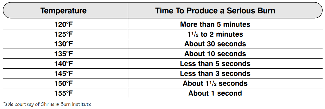
DANGER: There is a hot water scald potential if the thermostat is set too high. Households with small children, disabled, or elderly persons may require a 120°F or lower thermostat setting to prevent contact with HOT water.
The temperature of the water in the water heater can be regulated by setting the temperature dial of the adjustable surface mounted thermostat(s) located behind the jacket access panel(s).
Dual element heaters have two thermostats.
Safety and energy conservation are factors to be considered when selecting the water temperature setting of the water heater’s thermostat(s). The lower the temperature setting, the greater the savings in energy and operating costs.
To comply with safety regulations the thermostat(s) are factory set at 120°F or less where local codes require. This is the recommended starting point.
Water temperatures above 125°F can cause severe burns or death from scalding. Be sure to read and follow the warnings outlined in this manual and on the label on the water heater. This label is located on the water heater near the thermostat access panel.
Mixing valves for reducing point of use water temperature by mixing hot and cold water in branch water lines are available. Contact a licensed plumber or the local plumbing authority for further information.
The chart below may be used as a guide in determining the proper water temperature for your home.
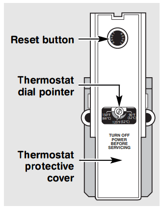
Type 59T thermostat and protective cover.
CAUTION: Shut off power to the water heater before draining water.
DANGER: Before manually operating the relief valve, make certain no one will be exposed to the hot water released by the valve. The water drained from the tank may be hot enough to present a scald hazard and should be directed to a suitable drain to prevent injury or damage.
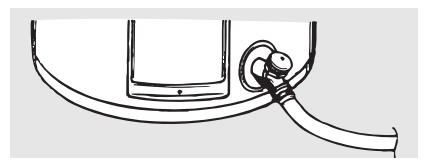
In order to drain the water heater, turn off the cold water supply. Open a hot water faucet or lift the handle on the relief valve to admit air to the tank.
Attach a garden hose to the drain valve on the water heater and direct the stream of water to a drain. Open the valve.
NOTICE: Refer to the Hydrogen Gas Caution in the Operating Instructions.
If the water heater is to remain idle for an extended period of time, the power and water to the appliance should be turned off to conserve energy and prevent a build-up of dangerous hydrogen gas.
The water heater and piping should be drained if they might be subjected to freezing temperatures.
After a long shut-down period, the water heater’s operation and controls should be checked by qualified service personnel. Make certain the water heater is completely filled again before placing it in operation.
DANGER: Before manually operating the relief valve, make certain no one will be exposed to the danger of coming in contact with the hot water released by the valve. The water may be hot enough to create a scald hazard. The water should be released into a suitable drain to prevent injury or property damage.
NOTICE: If the temperature and pressure relief valve on the hot water heater discharges periodically, this may be due to thermal expansion in a closed water system. Contact the water supplier or your plumbing contractor on how to correct this. Do not plug the relief valve outlet.
Properly maintained, your water heater will provide years of dependable troublefree service. It is suggested that a routine preventive maintenance program be established and followed by the user.
It is further recommended that a periodic inspection of the operating controls, heating element and wiring should be made by service personnel qualified in electric appliance repair.
Most electrical appliances, even when new, make some sound when in operation. If the hissing or singing sound level increases excessively, the electric heating element may require cleaning. Contact a qualified installer or plumbing contract to inspect.
At least once a year, lift and release the lever handle on the temperature pressure relief valve, located near the top of the water heater, to make certain the valve operates freely. Allow several gallons to flush through the discharge line to an open drain.
A water heater’s tank can act as a setting basin for solids suspended in the water.It is therefore not uncommon for hard water deposits to accumulate in the bottom of the tank. It is suggested that a few quarts of water be drained from the water heater’s tank every month to clean the tank of these deposits.
Rapid closing of faucets or solenoid valves in automatic water using appliances can cause a banging noise heard in a water pipe. Strategically located risers in the water pipe system or water hammer arresting devices can be used to minimize the problem.
The anode rod should be removed from the water heater’s tank annually for inspection and replaced when more than 6″ of core wire is exposed at either end of the rod.
Make sure the cold water supply is turned off before removing anode rod.
NOTICE: Do not remove the anode rod from the water heater’s tank, except for inspection and/or replacement, as operation with the anode rod removed will shorten the life of the glass lined tank and will exclude warranty coverage.
Problem | Possible Causes | What To Do |
Rumbling noise | Water conditions in your home caused a build up of scale or mineral deposits on the heating elements. | ● Remove and clean the heating elements. |
Relief valve producing popping noise or draining | Pressure build up caused by thermal expansion in a closed system. | ● This is an unacceptable condition and must be corrected. Contact the water supplier or plumbing contractor on how to correct this. Do not plug the relief valve outlet. |
Rattling noise during periods of water usage | Internal heat trap fittings in operation. | ● This is normal for heat trap fittings when in operation and does not indicate a need for service. |
Not enough or no hot water | Water usage may have exceeded the capacity of the water heater. | ● Wait for the water heater to recover after an abnormal demand. |
| A fuse is blown or a circuit breaker tripped. | ● Replace fuse or reset circuit breaker. |
Electric supply may be off. | ● Make sure electric supply to water heater and disconnect switch, if used, are in the ON position. | |
The thermostat may be set set too low. | ● See the Temperature regulation of the water heater section of this manual. | |
Leaking or open hot water faucets. | ● Make sure all faucets are closed. | |
Electric service to your home may be interrupted. | ● Contact the local electric utility. | |
Improper wiring. | ● See the Installing the water heater section of this manual. | |
Manual reset limit (ECO). | ● See the Temperature regulation of the water heater section of this manual. | |
Cold water inlet temperature may be colder during the winter months. | ● This is normal. The colder inlet water takes longer to heat. | |
Water is too hot | The thermostat is set too high. | ● See the Temperature regulation of the water heater section of this manual. |
For 20–120 gallon models with single and double elements.
Instructions For Placing a Parts Order
All parts orders should include:
CAUTION: For your safety DO NOT attempt repair of electrical wiring, thermostat(s), heating elements or other operating controls. Refer repairs to qualified service personnel.
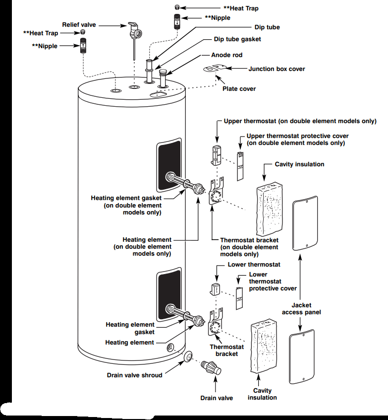
**Not supplied on all models
Reference file: GE GE50M6A SmartWater Electric Water Heater
Series: GE
Additionally, the document applies to other GE - General Electric models: