BELA30SS600-B
BELA36SS600-B
Installation Instructions
Use and Care Information
Instructions d'installation
Utilisez et d'entretien
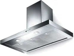
BELLA 30" / 36"

2
READ AND SAVE THESE INSTRUCTIONS BEFORE YOU START
INSTALLING THIS RANGEHOOD
WARNING: - TO REDUCE THE RISK OF A RANGE TOP GREASE FIRE:
a) Never leave surface units unattended at high settings. Boilovers cause smoking and
greasy spillovers that may ignite. Heat oils slowly on low or medium setting.
b)AlwaysturnhoodONwhencookingathighheatorwhenambeingfood(i.e.Crepes
Suzette, Cherries Jubilee, Peppercorn Beef Flambé).
c) Clean ventilating fans frequently. Grease should not be allowed to accumulate on fan
orlter.
d) Use proper pan size. Always use cookware appropriate for the size of the surface element.
WARNING: - TO REDUCE THE RISK OF INJURY TO PERSONS IN THE EVENT OF A
RANGE TOP GREASE FIRE, OBSERVE THE FOLLOWING*:
a)SMOTHERFLAMESwithaclose-ttinglid,cookiesheet,ormetaltray,thenturnofftheburner.
BECAREFULTOPREVENTBURNS.IftheamesdonotgooutimmediatelyEVACUATE
AND CALL THE FIRE DEPARTMENT.
b) NEVER PICK UP A FLAMING PAN - You may be burned.
c) DO NOT USE WATER, including wet dishcloths or towels - a violent steam explosion will
result.
d) Use an extinguisher ONLY if:
1. You know you have a Class ABC extinguisher, and you already know how to operate it.
2. Thereissmallandcontainedintheareawhereitstarted.
3. Theredepartmentisbeingcalled.
4. Youcanghttherewithyourbacktoanexit.
* Based on "Kitchen Firesafety Tips" published by NFPA
WARNING - TO REDUCE THE RISK OF FIRE OR ELECTRIC SHOCK, do not use this
fan with any solid-state speed control device.
WARNING - TO REDUCE THE RISK OF FIRE, ELECTRICAL SHOCK, OR INJURY TO
PERSONS, OBSERVE THE FOLLOWING:
1. Use this unit only in the manner intended by the manufacturer. If you have any
questions, contact the manufacturer.
2. Before servicing or cleaning unit, switch power off at service panel and lock the
service disconnecting means to prevent power from being switched on acciden-
tally. When the service disconnecting means cannot be locked, securely fasten a
prominent warning device, such as a tag, to the service panel.
CAUTION: For General Ventilating Use Only. Do Not Use To Exhaust Hazardous or
Explosive Materials and Vapors.
WARNING - TO REDUCE THE RISK OF FIRE, ELECTRICAL SHOCK, OR INJURY TO
PERSONS, OBSERVE THE FOLLOWING:
1. InstallationWorkAndElectricalWiringMustBeDoneByQualiedPerson(s)InAccor-
dance With All Applicable Codes And Standards, Including Fire-Rated Construction.
2. Sufcientairisneededforpropercombustionandexhaustingofgasesthrough
theue(chimney)offuelburningequipmenttopreventbackdrafting.Followthe
heating equipment manufacturer's guideline and safety standards such as those
publishedbytheNational FireProtectionAssociation(NFPA),andtheAmerican
SocietyforHeating,RefrigerationandAirConditioningEngineers(ASHRAE),and
the local code authorities.

3
3. When cutting or drilling into wall or ceiling, do not damage electrical wiring and
other hidden utilities.
4. Ducted fans must always be vented to the outdoors.
ALL WALL AND FLOOR OPENINGS WHERE THE RANGEHOOD IS INSTALLED MUST
BE SEALED.
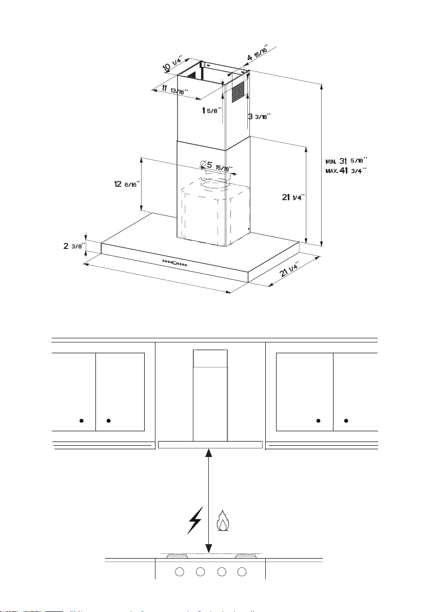
This rangehood requires at least 24" of clearance between the bottom of the rangehood
and the cooking surface or countertop. This hood has been approved by UL at this distance from
the cooktop.
This minimum clearance may be higher depending on local building codes. For gas cooktops and
combination ranges, a minimum of 30" is recommended and may be required.
Overhead cabinets on both sides of this unit must be a minimum of 18" above the cooking surface
or countertop. Consult the cooktop or range installation instructions given by the manufacturer
before making any cutouts.
MOBILE HOME INSTALLATION The installation of this rangehood must conform to the Manufactured
Home Construction and Safety Standards, Title 24 CFR, Part 3280 (formerly Federal Standard
for Mobile Home Construction and Safety, Title 24, HUD, Part 280). See Electrical Requirements.
• Venting system MUST terminate outside the home.
• DO NOT terminate the ductwork in an attic or other enclosed space.
• DO NOT use 4" laundry-type wall caps.
• Flexible-type ductwork is not recommended.
• DO NOT obstruct the ow of combustion and ventilation air.
• Failure to follow venting requirements may result in a re.
WARNING
!
VENTING REQUIREMENTS
Determine which venting method is best for your application. Ductwork can extend either through the
wall or the roof.
The length of the ductwork and the number of elbows should be kept to a minimum to provide efcient
performance. The size of the ductwork should be uniform. Do not install two elbows together. Use
duct tape to seal all joints in the ductwork system. Use caulking to seal exterior wall or oor opening
around the cap.
Flexible ductwork is not recommended. Flexible ductwork creates back pressure and air turbulence
that greatly reduces performance.
Make sure there is proper clearance within the wall or oor for exhaust duct before making cutouts.
Do not cut a joist or stud unless absolutely necessary. If a joist or stud must be cut, then a supporting
frame must be constructed.
WARNING - To Reduce The Risk Of Fire, Use Only Metal Ductwork.
CAUTION-Toreduceriskofreandtoproperlyexhaustair,besuretoductairoutside–Do
not vent exhaust air into spaces within walls or ceilings or into attics, crawl spaces, or garages.
Cold Weather installations
An additional back draft damper should be installed to minimize backward cold air ow and a
nonmetallic thermal break should be installed to minimize conduction of outside temperatures as
part of the vent system. The damper should be on the cold air side of the thermal break. The break
should be as close as possible to where the vent system enters the heated portion of the house.
4
• Electrical ground is required on this rangehood.
• If cold water pipe is interrupted by plastic, nonmetallic gaskets or other materials, DO
NOT use for grounding.
• DO NOT ground to a gas pipe.
• DO NOT have a fuse in the neutral or grounding circuit. A fuse in the neutral or
grounding circuit could result in electrical shock.
• Check with a qualied electrician if you are in doubt as to whether the rangehood is
properly grounded.
• Failure to follow electrical requirements may result in a re.
WARNING
!
StateofCaliforniaProposition65Warning(USonly)
WARNING
This product contains chemicals known to the State of California to cause cancer and birth
defects or other reproductive harm.
For more information go to www.P65Warnings.ca.gov
ELECTRICAL REQUIREMENTS
A 120 volt, 60 Hz AC-only electrical supply is required on a separate 15 amp fused circuit.
A time-delay fuse or circuit breaker is recommended. The fuse must be sized per local
codes in accordance with the electrical rating of this unit as specied on the serial/rating
plate located inside the unit near the eld wiring compartment.

5
RANGEHOOD DIMENSIONS
29
-1/2" -
35
-1/2"
Min. 24" Min. 30"
6
2.2
2.1
10
7.2.1
12a
12b
1
12d
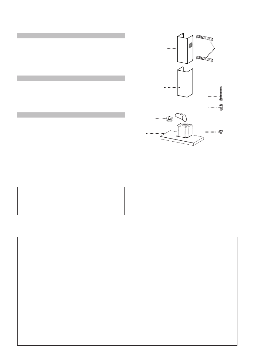
MAIN PARTS
Components
Ref. Qty. Product Components
1 1 Hood Body, complete with: Con-
trols, Light, Filters, Blower.
2 1 Telescopic Chimney comprising:
2.1 1 Upper Section
2.2 1 Lower Section
10 1 Damper ø 5 7/8"
Ref. Qty. Installation Components
7.2.1 2 Upper Chimney Section Fixing
Brackets
12a 6 Screws 3/16" x 1 3/4"
12b 4 Screws 1/8" x 7/16"
12d 2 Screws 1/8" x 5/16"
Qty. Documentation
1 Instruction Manual
Available Accessories
Parts needed
- 6" Round Metal ductwork
- Direct Connect Wiring Box sku # number: - WIREBOX
-HighCeilingChimneyKit-UpperandLowerChimneyFluetoreplacetheoriginalue's
totupto11'ceilings-sku#HIGH3
- Ductless Kit - Includes Ductless Diverter, Charcoal Filters - sku# DUCT4
- 6" Make-Up Air Damper Kit - MUDAMPER6
- 8" Make-Up Air Damper Kit - MUDAMPER8
- CFM Reducer Kit - CFMRED
- Activated Charcoal Filter Accessory - sku# FILTER2
- Wireless Remote Control Accessory - REMCTRL

7
H
I
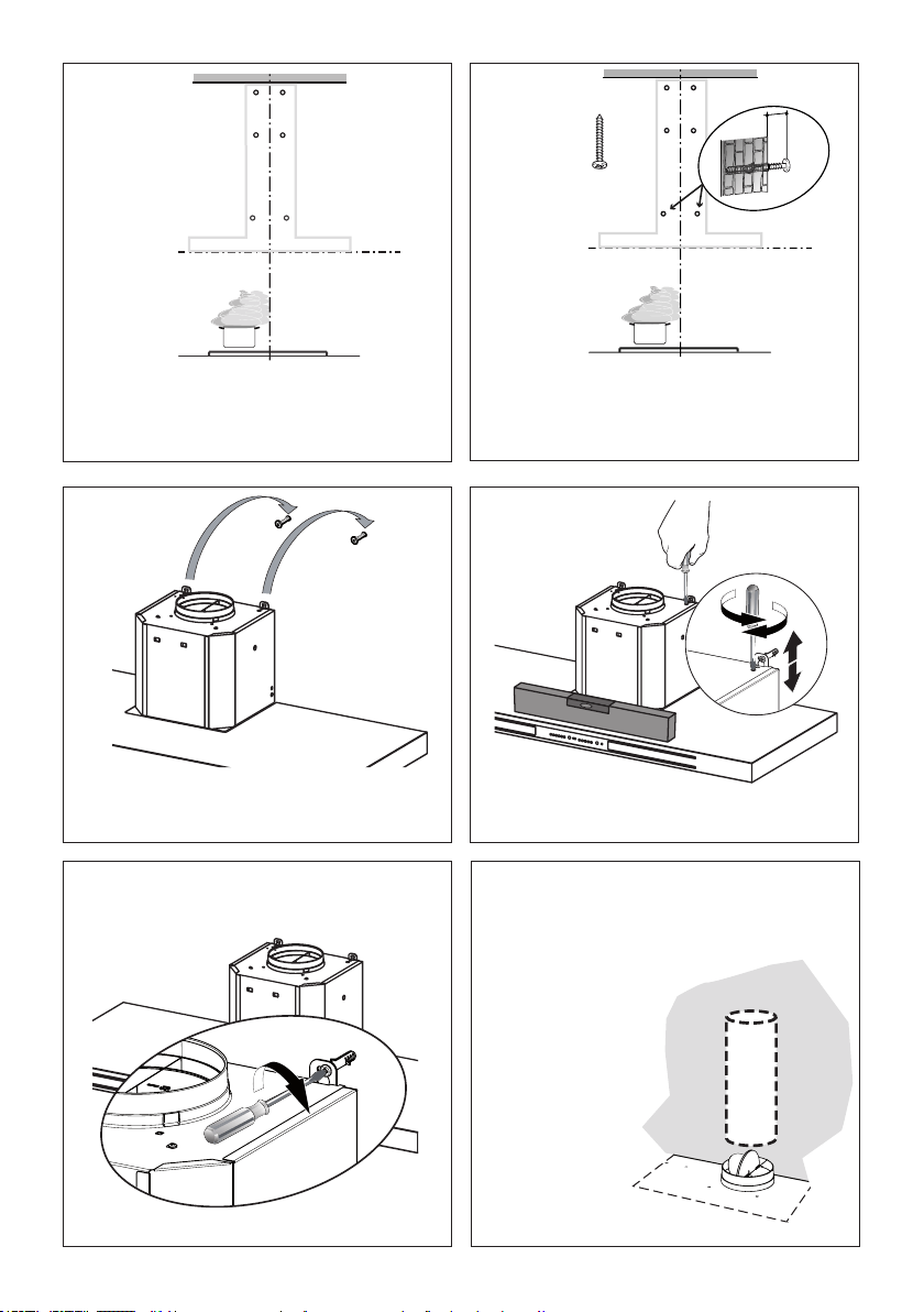
Install Damper that is included with the Hood
before connecting to the ductwork.
Only for Ducted Venting Installation
Choose your ducting method
Non Ducted - Recirculation OptionDucted Venting Options Installation
Requires
purchase of
Activated
Charcoal
Accessory
Horizontal
Vertical
6 "
8
2
x6
x6
12 5/8”
4 9/16”
´
>
´
´
´
4 9/16”
7.2.1
2.1
2.1
1
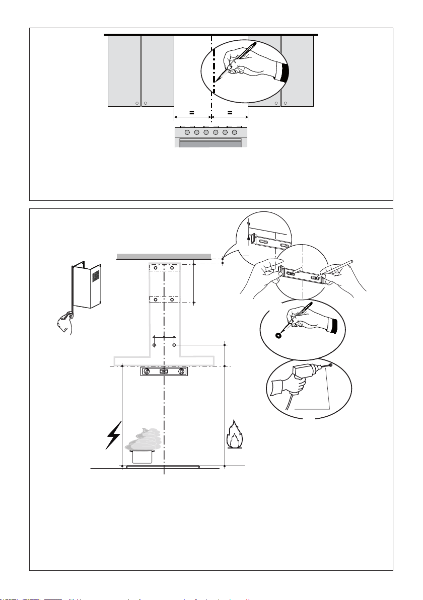
Draw a vertical line on the supporting wall as high as practical, at the center of the area in which
the hood will be installed.
Drawahorizontallineatwherethebottomedgeofthehoodwillbelocatedasindicatedinthegure
that is a minimum of 24" electric and 30" gas above cooking surface.
Draw a horizontal line where indicated above the cooking surface.
Place a bracket 7.2.1 on the wall as shown about 1/8" from the ceiling or upper limit, aligning the center
(notch) with the vertical reference line and mark the wall at the centers of the holes in the bracket.
Placethesecondbracket7.2.1onthewallasshown,belowtherstbracket,attheheightofthe
upper chimney section supplied and aligning the center (notch) with the vertical line.
Mark the wall at the centers of the holes in the bracket and mark the point 1 and 2 for the Hood Body
installation as shown(12 5/8" from the horizontal line and 4 9/16" from the vertical line).
Drill ø 5/16" holes at all the center points marked (point 1,2,3,4,5,6) as shown.
9
7
3
4
5
6
12a
Installation screws provided must be secured
with wall plugs (purchase separately).
Insert the two screws 12a supplied with the hood
as shown and do not tighten all the way to wall
leaving 3/16" of the screw heads exposed.
Use a level to level the hood body by the screws
as show.
Hook the hood body onto the two screws as show.
I = 6x
11
8
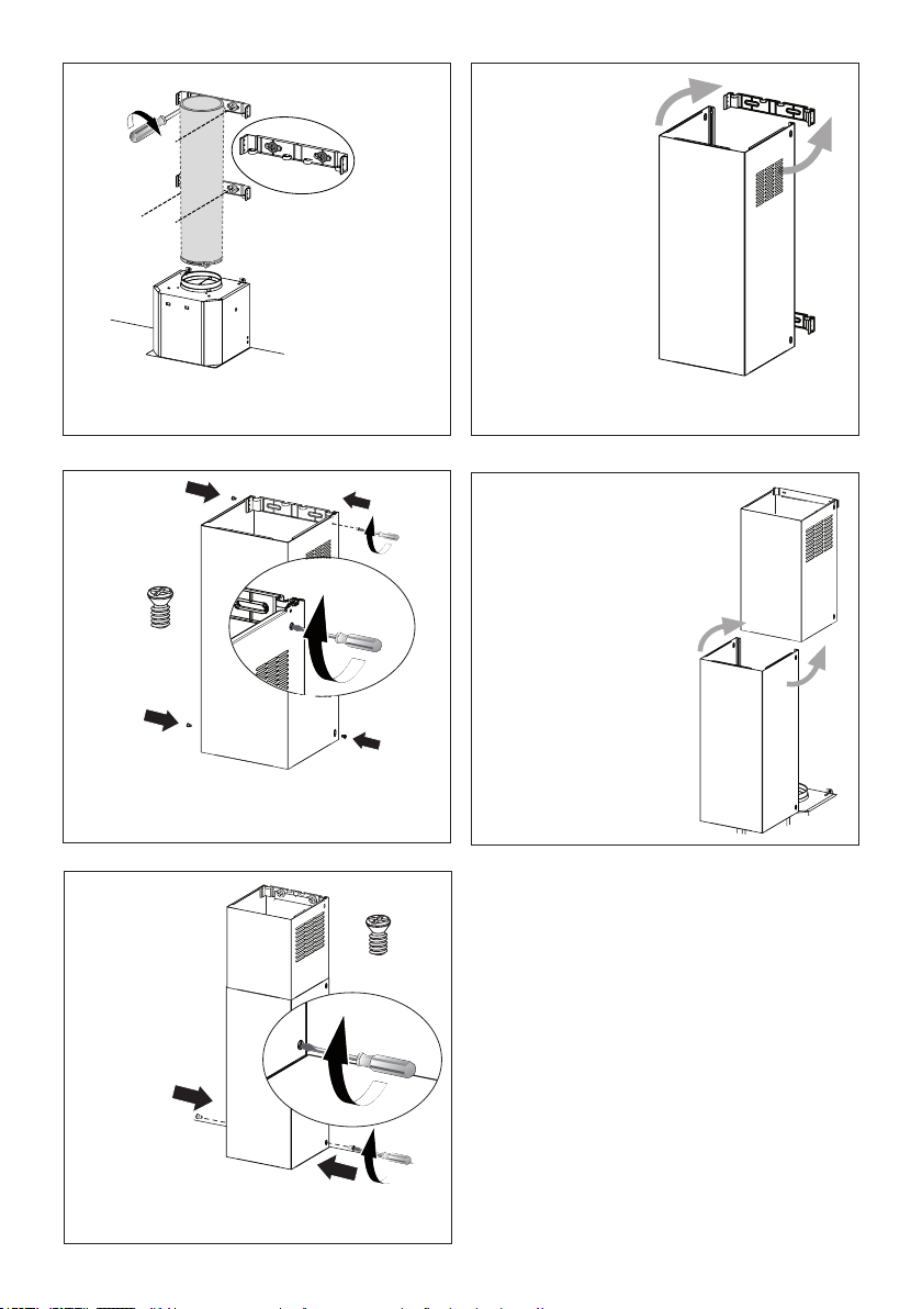
Install Roof or Wall
Cap purchased
separately. Con-
nect the 6" metal
ductwork to the
Roof or Wall Cap
and then attach
ductwork.
Vertical or Horizontal
Ducting Installation
Tighten the 2 screws 12c as shown.
2.
´
10
9
L = 4x
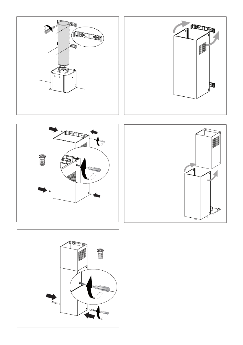
Installthe2xingbrackets7.2.1tothemiddleand
upper holes and secure with screws 12a as shown.
10
11
2.1
N = 4x
12b
Slightly widen
the two sides
of the upper
chimney and
hook them
behind the
brackets 7.2.1,
making sure
that they are
well seated.
Secure the sides to the brackets by using the 4
screws 12b.
12a
N = 2x
12d
2.2
2.1
13
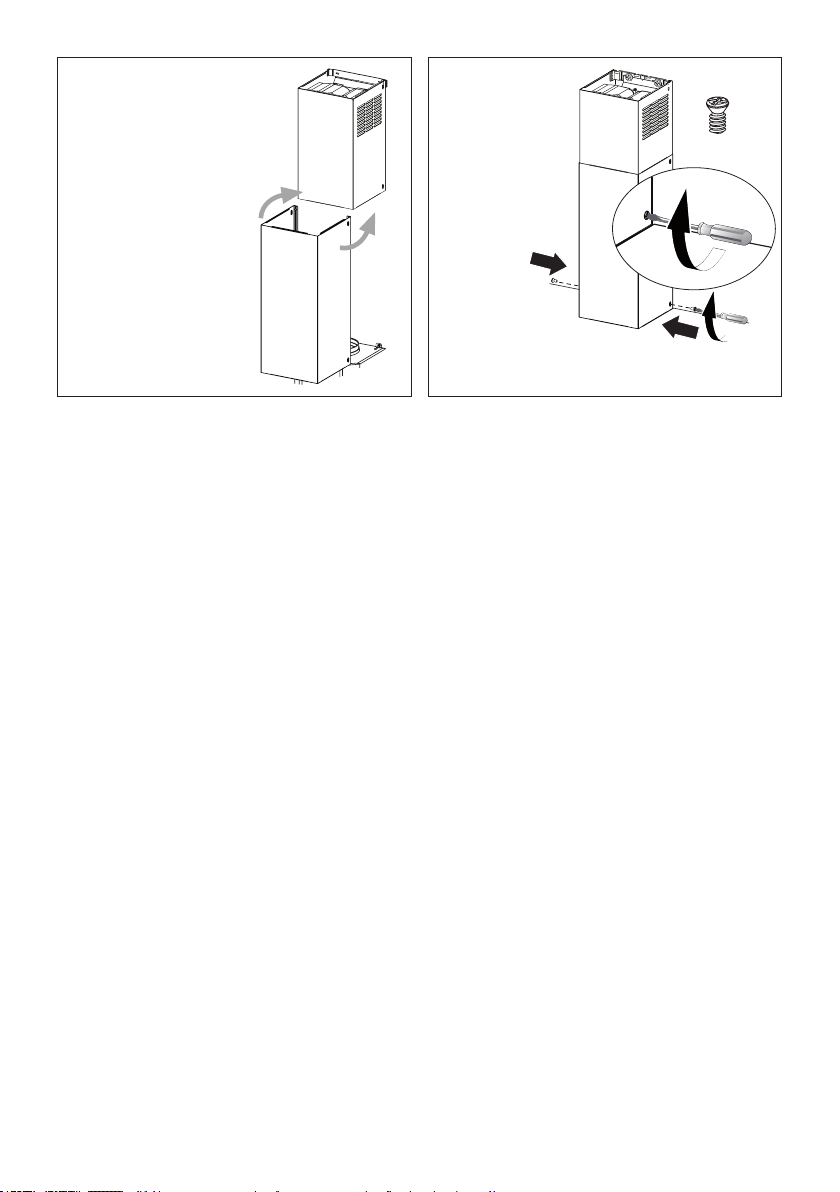
Slightly widen the two
sides of the the lower
chimney hood and hook
them between
the upper section and the
wall, making sure that they
are properly housed.
Fix the the
lower chim-
ney hood
laterally to
the hood
body using
the 2 screws
12d supplied.
12

11
16 17
18
2.1
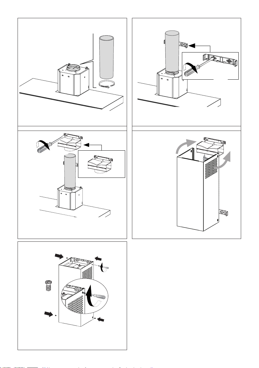
Fix the Ductless Diverter with two screws 12a supplied
as shown.
Slightly widen
the two sides of
the upper chim-
ney and hook
them behind
the brackets
and connect to
the Ductless
Diverter, mak-
ing sure that
they are well
seated.
14 15
¡
12a
Only for the recirculation version, connect the hood
to the Air outlet.
Fix the lower Bracket 7.2.1 with two screws 12a
supplied as shown.
Non-Ducted Recirculation Option
N = 4x
12b
Secure the sides to the brackets by using the 4
screws 12b.

12
Direct Connect Wiring Box
Accessory sku # WIREBOX
(purchased separately)
Created by
-
Denomination
-
Lang EN
Sheet
1
/1
Modif.by
Approved by
Approval date
Doc. status
Drawing N.
NEW_DRAWING_BOX
Rev
01
ELECTRICAL INSTALLATION WITH CONNECTION
CABLE
GROUNDINGINSTRUCTIONSThisappliance must be
grounded. In the event of an electrical short circuit, grounding
reduces the risk of electric shock by providing an escape
wire for the electric current. This appliance is equipped
with a cord having a grounding wire with a grounding plug.
The plug must be plugged into an outlet that is properly
installed and grounded.
WARNING - Improper grounding can result in a risk of
electric shock.
Consultaqualiedelectricianifthegroundinginstructions
are not completely understood, or if doubt exists as to
whether the appliance is properly grounded.
Do not use an extension cord. If the power supply cord is
tooshort,haveaqualiedelectricianinstallanoutletnear
the appliance.
ELECTRICAL INSTALLATION WITH
OPTIONAL WIRING BOX
For Permanent wiring Installation-Use only
with Listed rangehood Wiring Box kit
sku # WIREBOX, manufactured by Faber.
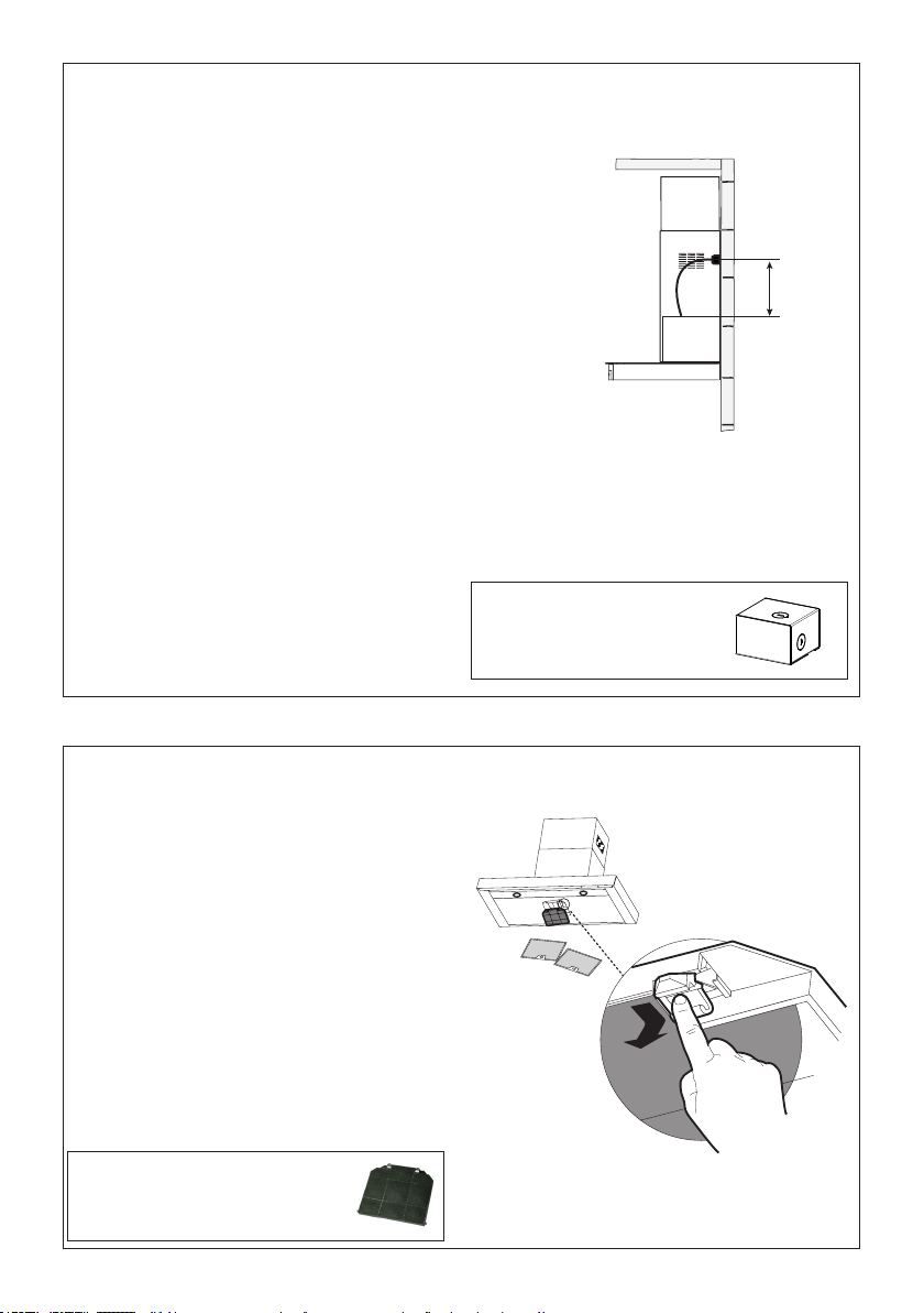
Max. 33 7/16”
19
For Non-Ducted Recirculation
Option
Required Activated Charcoal Filter
Accessory - sku # - FILTER2
(purchased separately)
Attach a
charcoal
lterinthe
correct
position and
block it by
thexing
hooks as
shown.
Unlockthexinghooks(towardsthebackofthe
hood) to remove.
13
N = 2x
12d
2.2
2.1
20 21
Slightly widen the two
sides of the the lower
chimney hood and hook
them between
the upper section and the
wall, making sure that they
are properly housed.
Fix the the
lower chim-
ney hood
laterally to
the hood
body using
the 2 screws
12d supplied.
14
USE AND CARE INFORMATION
For Best Results
Starttherangehoodseveralminutesbeforecookingtodevelopproperairow.Allowtherangehoodto
operate for several minutes after cooking is complete to clear all smoke and odors from the kitchen.
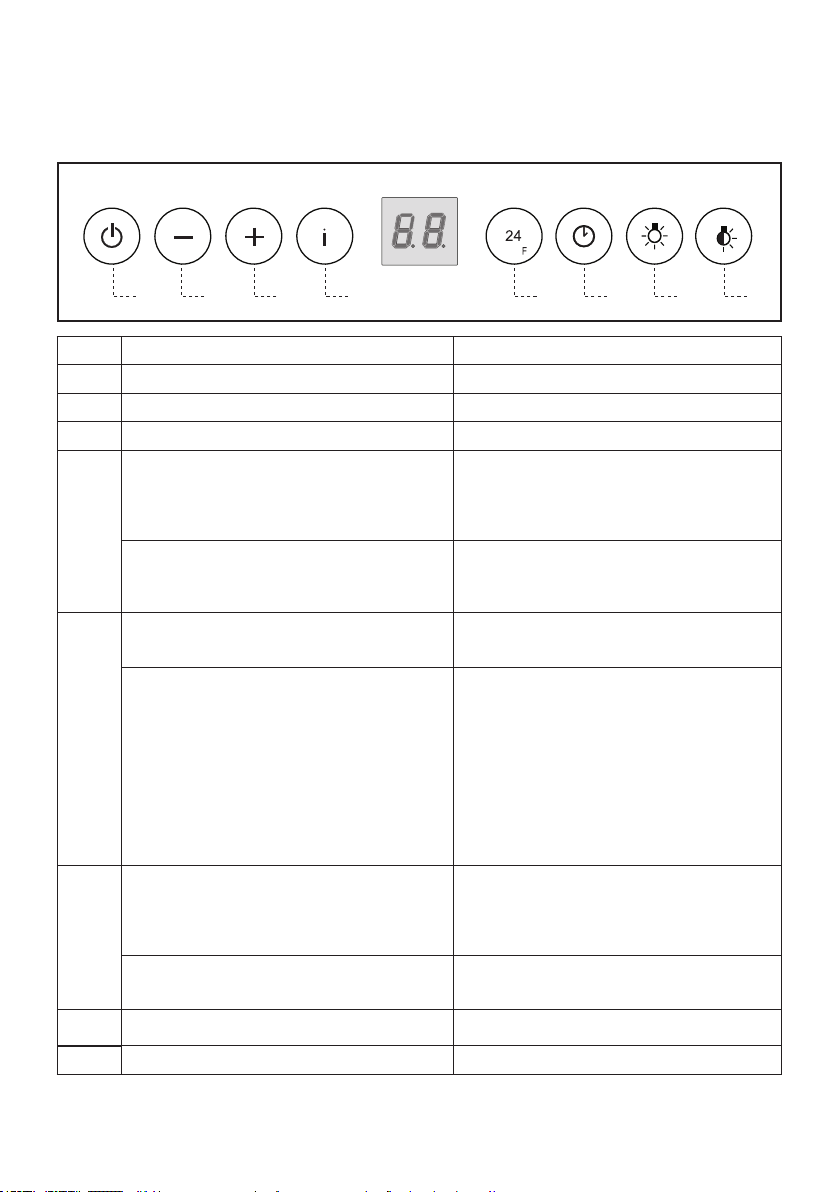
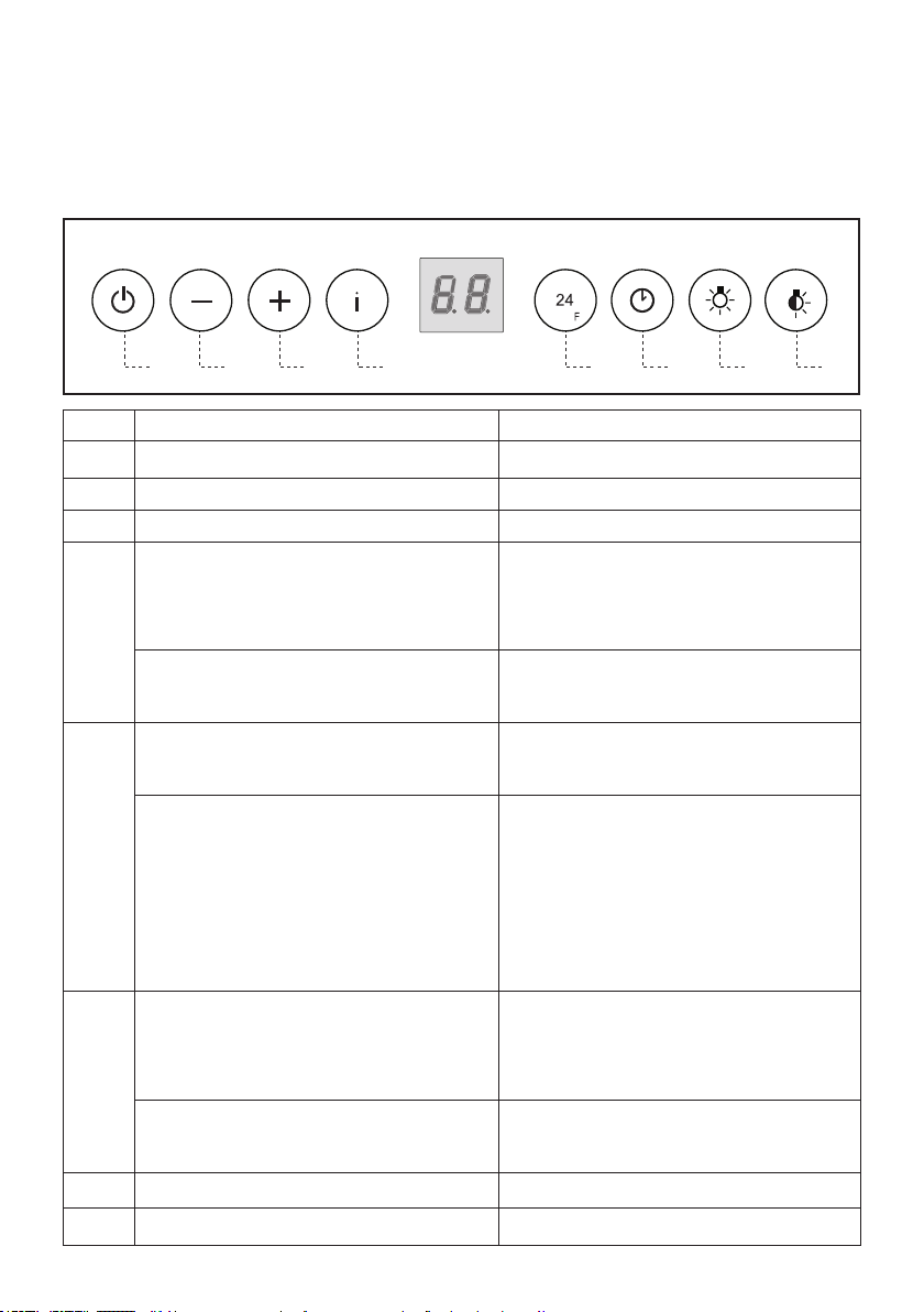
Button Function Display
A Turns the suction motor on and off at speed one. Displays the set speed
B Decreases the working speed. Displays the set speed
C Increases the working speed. Displays the set speed
D Activate intensive speed from any other speed,
including motor off. This speed is set to operate for
6 minutes, after which the system returns to the
speedthatwassetbefore.Suitabletodealwith
maximum levels of cooking fumes.
Displays HI and the time remaining once very
second.
Press and hold the button for approximately 5
seconds, with all the loads turned off (Motor and
Lights), to turn the Activated Charcoal Filter alarm
On and Off.
FC+Punto(2ashes)–AlarmOn.
FC+Punto(1ash)–AlarmOff.
E
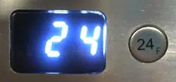
24H function
Turns the suction motor on at speed one and effects
one 10 minute extraction every hour.
Displays24andthespotatthebottomrightashes
once every second, while the motor is running.
It is disabled by pressing the button.
Whentheltersalarmistriggered,thealarmcan
be reset by pressing and holding this button for
approximately 3 seconds.
These indications are only visible when the motor
is turned off.
FFashesthreetimes.
When the procedure terminates, the indication
shown previously turns off:
FG indicatestheneedtowashthemetal
greaselters.ThealarmistriggeredaftertheHood
has been in operation for 100 working hours.
FC indicates the need to change the
activatedcharcoallters,andalsotowashthe
metalgreaselters.Thealarmistriggeredafterthe
Hood has been in operation for 200 working hours.
F Delay function
Activate automatic switch-off with a 30’ delay.
Suitabletocompleteeliminationofresidualodours.
Can be activated from any position, and is disabled
by pressing the button or turning the motor off.
Displays the operating speed and the spot at the
bottomrightashesonceasecond.
Press and hold the button for approximately 5
seconds, with all the loads turned off (Motor and
Lights), to turn the Remote Control On and Off.
IR+Punto(2ashes)–RemoteControlOn.
IR+Punto(1ash)–RemoteControlOff.
G
Turns the lighting system on and off at maximum
intensity.
H
Turns the Courtesy Lighting on and off.
15
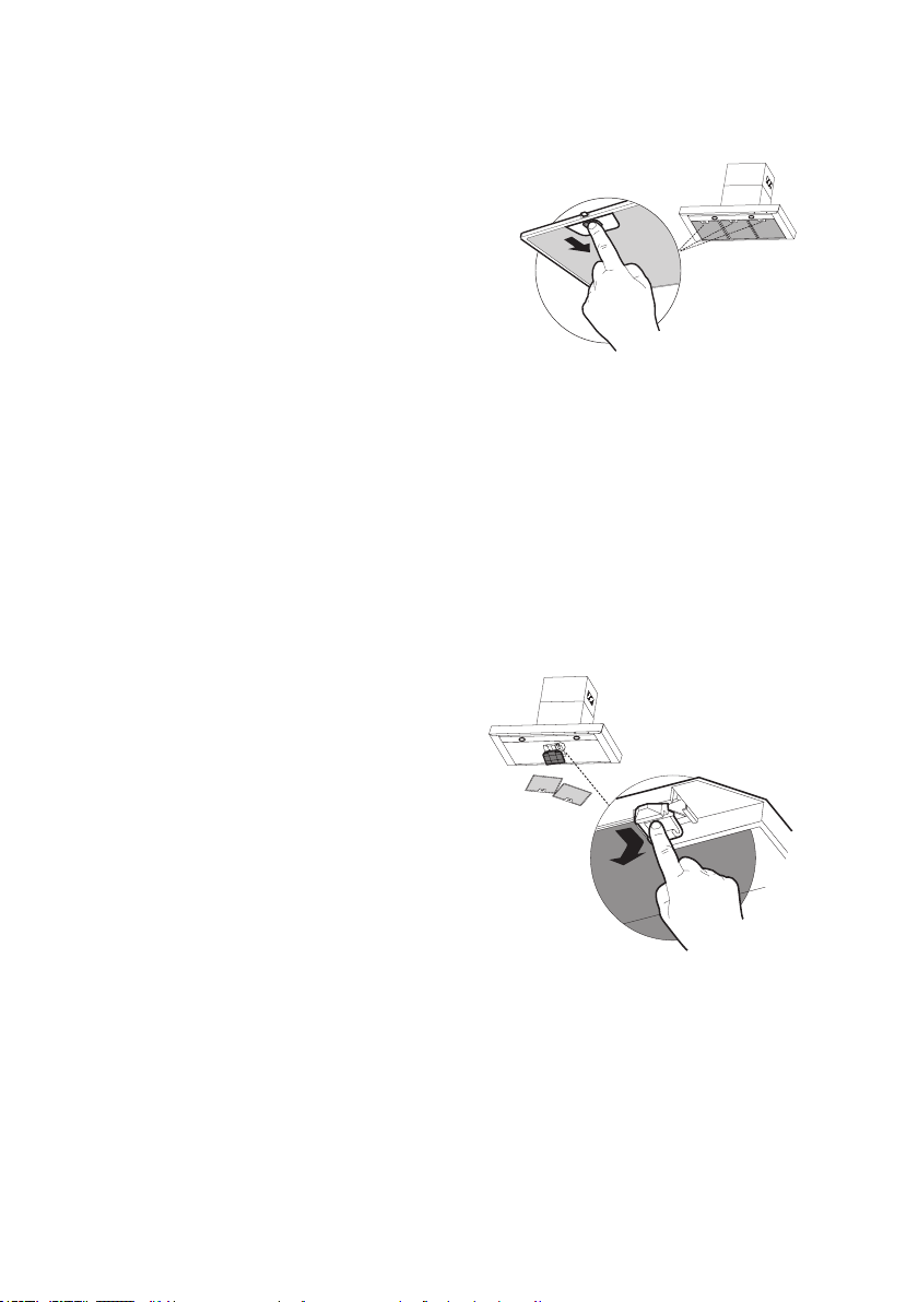
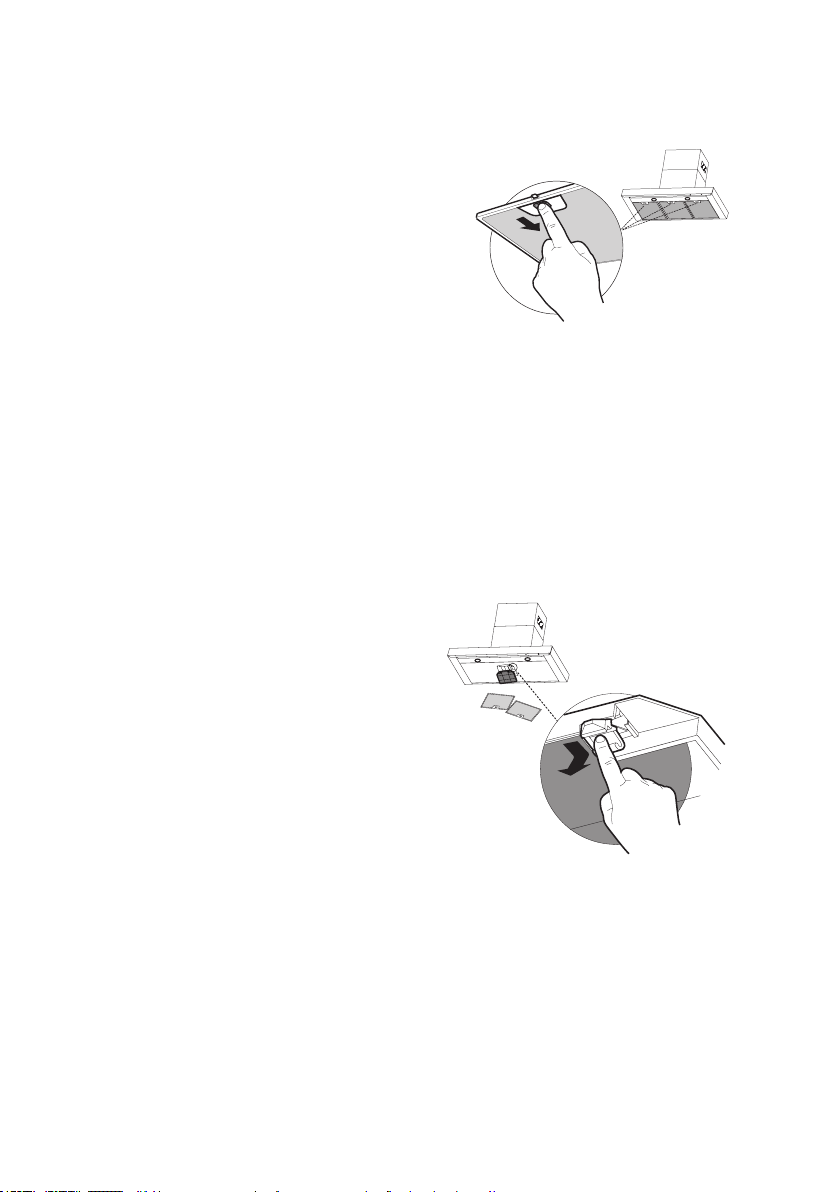
Cleaningmetalgreaselters
They can be washed in the dishwasher, and need to be cleaned
whenever the FG sign appears on the display or at least once
every 2 months use, or more frequently if use is particularly
intensive.
Resetting the alarm signal
• Turn the Lights and the Suction motor off, then disable the
24h function, if enabled.
• Press button E (see the paragraph on Use).
Cleaning the Filters
• Remove the Filters one at a time, pushing them towards
the back of the unit and at the same time pulling downward.
• Wash the Filters without bending them, and leave them to
dry completely before replacing. (If the surface of the lter
changes colour as time goes by, this will have absolutely no
effect on the efciency of the lter itself.)
• Replace, taking care to ensure that the handle faces forwards.
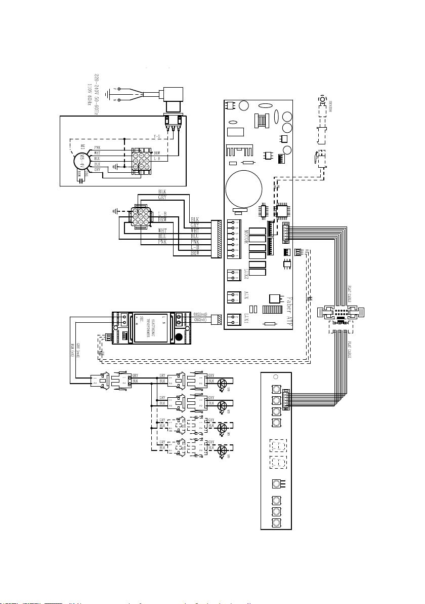
Replacing Activated Charcoal Filter
It cannot be washed or regenerated, and must be changed when
the FC symbol on the display appears, or at least once every 4
months. The Alarm signal, if it has been activated, only appears
when the Suction motor is turned on.
Resetting the alarm signal
• Turn the Lights and the Suction motor off, then disable the
24h function, if enabled.
• Press button E (see the paragraph on Use).
Cleaning the Filters
• Remove the Filters one at a time, pushing them towards
the back of the unit and at the same time pulling downward.
• Remove the saturated charcoal lter by releasing the xing
hooks.
• Fit the new lter and fasten it in its correct position.
• Replace, taking care to ensure that the handle faces forwards.
Lighting unit
• LED lights must be replaced by Faber factory authorized
service.
16
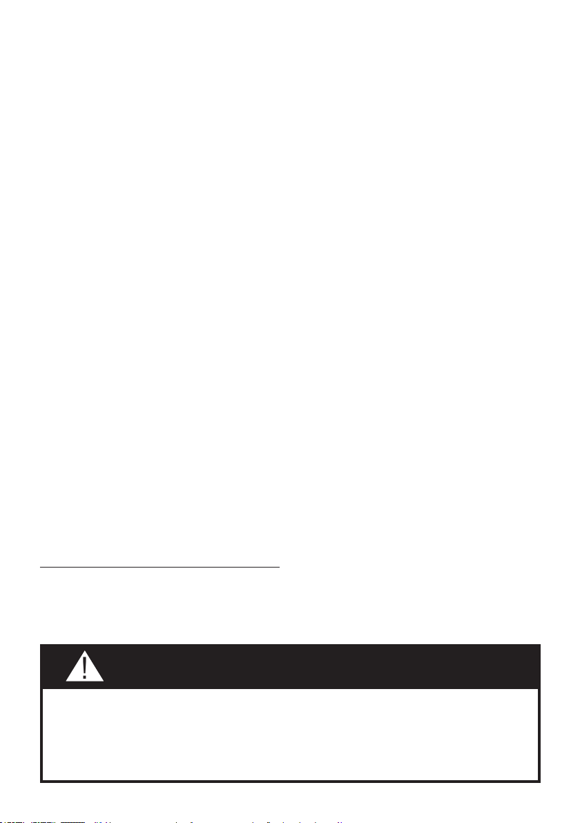
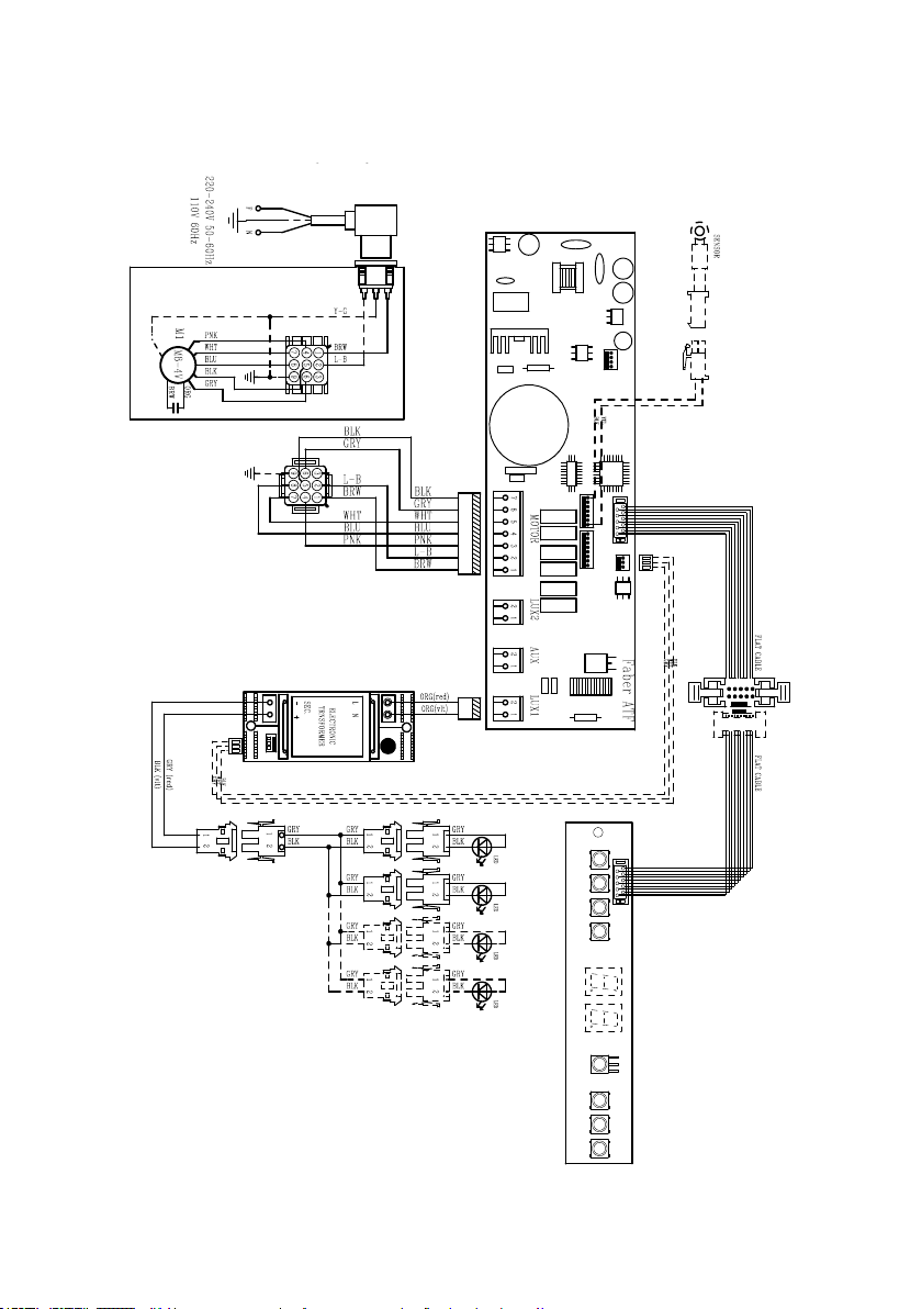
Wiring Diagram
991.0442.621 H90-308 r1
D002937_00
991.0442.621 H90-308 r1
D002937_00
17
January 4, 2016
FABER CONSUMER WARRANTY & SERVICE
All Faber products are warranted against any defect in materials or workmanship for the original purchaser
for a period of 1 year from the date of original purchase (requires proof of purchase). This warranty covers
labor and replacement parts. Faber, at its option, may repair or replace the product or components
necessary to restore the product to good working condition. To obtain warranty service, contact the dealer
from whom you purchased the range hood, or the local Faber distributor. If you cannot identify a local Faber
distributor, contact us at (508) 358-5353 for the name of a distributor in your area.
The following is not covered by Faber's warranty:
1. Service calls to correct the installation of your range hood, to instruct you how to use your range hood, to
replace or repair house fuses or to correct house wiring or plumbing.
2. Service calls to repair or replace range hood light bulbs, fuses or filters. Those consumable parts are
excluded from warranty coverage.
3. Repairs when your range hood is used for other than normal, single-family household use.
4. Damage resulting from accident, alteration, misuse, abuse, fire, flood, acts of God, improper installation,
installation not in accordance with electrical or plumbing codes or Faber documentation, or use of products
not approved by Faber.
5. Replacement parts or repair labor costs for units operated outside the United States or Canada, including
any non-UL or C-UL approved Faber range hoods.
6. Repairs to the hood resulting from unauthorized modifications made to the range hood.
7. Expenses for travel and transportation for product service in remote locations and pickup and delivery
charges. Faber range hoods should be serviced in the home.
THIS WARRANTY DOES NOT ALLOW RECOVERY OF INCIDENTAL OR CONSEQUENTIAL DAMAGES, INCLUDING, WITHOUT
LIMITATION, DIRECT, INDIRECT, INCIDENTAL, SPECIAL OR CONSEQUENTIAL DAMAGES, PERSONAL INJURY/WRONGFUL
DEATH OR LOST PROFITS FABER WARRANTY IS LIMITED TO THE ABOVE CONDITIONS AND TO THE WARRANTY PERIOD
SPECIFIED HEREIN AND IS EXCLUSIVE. EXCEPT AS EXPRESSLY SPECIFIED IN THIS AGREEMENT, FABER DISCLAIMS ALL
EXPRESS OR IMPLIED CONDITIONS, REPRESENTATIONS, AND WARRANTIES INCLUDING, WITHOUT LIMITATION, ANY
IMPLIED WARRANTIES OF MERCHANTABILITY OR FITNESS FOR A PARTICULAR PURPOSE
.
This warranty gives you specific legal rights that may vary from state to state.
Model#: ______________________________ Serial #: _____________________________

18
VEUILLEZ LIRE ET CONSERVER LA PRÉSENTE NOTICE AVANT DE
COMMENCER L'INSTALLATION DE LA HOTTE DE CUISINE
AVERTISSEMENT:-POUR RÉDUIRE LE RISQUE D'UN FEU DE GRAISSE SUR LA TABLE DE
CUISSON:
a) Ne laissez jamais sans surveillance les éléments de la surface de cuisson à température élevée.
Les bouillonnements excessifs peuvent provoquer de la fumée et les débordements de graisse
peuvents'enammer.L'huiledoitêtrechaufféelentement,àunetempératurebasseoumoyenne.
b) Assurez-vous de toujours mettre en marche le ventilateur de la hotte lorsque vous cuisinez
àtempératureélevéeoupréparezunmetsambé(p.ex.crêpesSuzette,cerisesjubilé,bœuf
ambé).
c) Nettoyez régulièrement les ventilateurs d'aspiration. Assurez-vous de ne pas laisser de la graisse
s'accumulersurleventilateurouleltre.
d)Utiliseztoujoursdespoêlesetcasserolesdelatailleappropriée.Utiliseztoujoursdesustensiles
de cuisine de la taille adaptée à celle de l'élément chauffant.
AVERTISSEMENT:-POURPRÉVENIRLESBLESSURESENCASDEFEUDEGRAISSESURLA
TABLEDECUISSON,SUIVEZLESRECOMMANDATIONSSUIVANTES*:
a) ÉTOUFFEZ LES FLAMMES à l'aide d'un couvercle hermétique, d'une plaque à biscuits ou d'un
plateau métallique, puis éteignez le brûleur. FAITES ATTENTION AUX BRÛLURES. Si le feu ne
s'éteint pas immédiatement, QUITTEZ LES LIEUX ET APPELEZ LES POMPIERS.
b) NE PRENEZ JAMAIS UNE CASSEROLE EN FLAMME - Vous pourriez vous brûler.
c) N'UTILISEZ JAMAIS DE L'EAU, ni un linge à vaisselle ou un torchon mouillé, pour éteindre le feu.
Cela pourrait provoquer une violente explosion de vapeur.
d)UtilisezunextincteurUNIQUEMENTsi:
1. Vousêtescertainqu'ils'agitd'unextincteurdeclasseABCetquevousconnaissezbienson
mode d'emploi.
2. Le feu est de faible intensité et se limite à l'endroit où il a démarré.
3. Les pompiers ont déjà été appelés.
4. Unevoiedesortiesetrouvederrièrevouspendantquevouséteignezlesammes
* D'après le guide «Kitchen Firesafety Tips» publié par la NFPA aux États-Unis
AVERTISSEMENT - POUR RÉDUIRE LE RISQUE D'INCENDIE OU DE CHOC ÉLECTRIQUE, n'utilisez
jamais ce ventilateur en association avec un dispositif de réglage de vitesse à semi-conducteurs.
AVERTISSEMENT - POUR RÉDUIRE LES RISQUES D'INCENDIE, DE CHOC ÉLECTRIQUE OU DE
BLESSURECORPORELLE,RESPECTEZLESINSTRUCTIONSSUIVANTES:
1. Utilisez cet appareil uniquement de la façon prévue par le fabricant. Pour toute question, com-
muniquez avec le fabricant.
2. Avant de procéder à l'entretien ou au nettoyage de l'appareil, coupez l'alimentation au niveau du
panneau électrique et verrouillez-le pour vous assurer que l'électricité n'est pas rétablie accidentel-
lement.S'iln'estpaspossibledeverrouillerledispositifd'interruptiondel'alimentation,afchezde
façon ferme et bien visible un avis de danger, par exemple à l'aide d'une étiquette sur le panneau.
ATTENTION:Destinéàunusagedeventilationgénéraleuniquement.N'utilisezpascedispositif
pour l'aspiration de vapeurs ou de matériaux dangereux ou explosifs.
AVERTISSEMENT - POUR RÉDUIRE LES RISQUES D'INCENDIE, DE CHOC ÉLECTRIQUE OU DE
BLESSURECORPORELLE,RESPECTEZLESINSTRUCTIONSSUIVANTES:
1. L'installationetlebranchement électriquedoiventêtreréalisésparun technicienqualiéet
conformément à tous les codes et normes en vigueur, incluant ceux concernant la construction
à l'épreuve du feu.
2. Andegarantirunecombustionetuneévacuationadéquatesdesgazparlesconduitesdela
cheminée des appareils à combustion, une bonne aération est nécessaire pour éviter le refou-
lement. Respectez les lignes directrices fournies par le fabricant du matériel chauffant, ainsi que
lesnormesdesécuritécommecellespubliéesparlaNationalFireProtectionAssociation(NFPA)
etlaAmericanSocietyforHeating,RefrigerationandAirConditioningEngineers(ASHRAE)aux
États-Unis, ainsi que les codes en vigueur dans votre région.
19
3. Lorsque vous faites une ouverture ou percez dans un mur ou le plafond, veillez à ne pas
endommagerleslsélectriquesoud'autresdispositifscachés.
4. Lesventilateurscanalisésdoiventtoujoursêtreraccordésàl'extérieur.
TOUTE OUVERTURE DANS LE MUR OU LE PLANCHER À PROXIMITÉ DE LA
HOTTE DOIT ÊTRE SCELLÉE.
Un espace libre d'au moins 24" est requis entre le bas de la hotte et la surface de cuisson
ou le comptoir. Cette hotte a été homologuée par l'UL à cette distance de la surface de cuisson.
L’espace libre minimal requis peut-être plus grand, selon la réglementation en matière de
construction de votre région. Pour les cuisinières à gaz et les cuisinières combinées, un
espace minimal de 30" est recommandé et pourrait être exigé.
Les armoires suspendues de chaque côté de l'appareil doivent se trouver à au moins 18"
de la surface de cuisson ou du comptoir. Consultez la notice d'installation de la surface de
cuisson ou de la cuisinière fournie par le fabricant avant de pratiquer des ouvertures.
INSTALLATION DANS UNE MAISON MOBILE L'installation de cette hotte doit être conforme
à la Partie 3280 de la norme Manufactured Home Construction and Safety Standards, Title 24
CFR (précédemment la partie 280 de la norme Federal Standard for Mobile Home Construction
and Safety, Title 24, HUD). Consultez la che technique électrique.
• Le système de ventilation DOIT déboucher à l'extérieur.
• NE FAITES PAS déboucher les conduits dans un grenier ou un autre endroit fermé.
• N'UTILISEZ PAS un clapet de sécheuse mural de 4po.
• Il n'est pas recommandé d'utiliser des conduits exibles.
• N'ENTRAVEZ PAS le ux de l'air de combustion et de ventilation.
• Le non-respect des exigences en matière de ventilation pourrait entraîner un incendie.
AVERTISSEMENT
!
CRITÈRES DE VENTILATION
Déterminez quelle méthode de ventilation est mieux adaptée à votre application. Les conduits peuvent
passer par le mur ou le toit.
Pour garantir une meilleure efcacité, la longueur des conduits et le nombre de coudes doivent être le plus
limités que possible. Le diamètre des conduits devrait être uniforme. N'installez pas deux coudes ensemble.
Utilisez un ruban pour canalisations an de sceller tous les joints du système de conduits. Utilisez un calfeu-
trage pour sceller les ouvertures dans le mur extérieur ou le plancher, autour du clapet.
Il n'est pas recommandé d'utiliser des conduits flexibles. Les conduits flexibles provoquent une contre-pression
et de la turbulence qui diminuent grandement l'efficacité de l'appareil.
Assurez-vous que l'espace libre dans le mur ou le plancher est sufsant pour le conduit d'évacuation avant de
pratiquer les ouvertures. Ne coupez jamais une poutre ou un chevron, sauf si c'est absolument nécessaire.
S'il s'avère nécessaire de couper une poutre ou un chevron, la construction d'un renforcement est requise.
AVERTISSEMENT - Pour réduire le risque d'incendie, utilisez uniquement des conduits métalliques.
ATTENTION - Pour réduire le risque d'incendie et pour évacuer adéquatement l'air, assurez-vous
deraccorderlesconduitsàl'extérieur–Nediffusezpasl'aird'évacuationdansdesespacesà
l'intérieur des murs ou du plafond, ou encore à l'intérieur d'un grenier, d'une galerie technique
ou d'un garage.
Installation dans les climats froids
Le système de ventilation doit prévoir un registre antirefoulement supplémentaire pour réduire le
ux d'air froid inverse, ainsi qu'une barrière thermique non métallique pour réduire la conduction
des températures extérieures. Le registre doit être installé du côté air froid par rapport à la barrière
thermique. La barrière thermique doit être positionnée le plus près que possible de l'endroit où le
système de ventilation pénètre dans la partie chauffée de la maison.
20
• Une mise à la terre électrique est requise pour cette hotte.
• N'UTILISEZ PAS un tuyau d'eau froide pour la mise à la terre si celui-ci est branché par des
joints en plastique, par des rondelles non métalliques ou d'autres matériaux.
• N'UTILISEZ PAS une conduite de gaz pour la mise à la terre.
• N'INSTALLEZ PAS un fusible sur le circuit neutre ou le circuit de mise à la terre. La présence
d'un fusible dans le circuit neutre ou de mise à la terre peut entraîner un choc électrique.
• Consultez un électricien qualié si vous n'êtes pas certain de la mise à la terre de la hotte.
• Le non-respect des exigences de la che technique électrique pourrait entraîner un incendie.
AVERTISSEMENT
!
Avertissementdelaproposition65del'ÉtatdeCalifornie(USseulement)
ATTENTION
Ce produit contient des produits chimiques connus de l'État de Californie pour causer le
cancer et des malformations congénitales ou d'autres problèmes de reproduction.
Pour plus d'informations, visitez www.P65Warnings.ca.gov
FICHE TECHNIQUE ÉLECTRIQUE
Une alimentation de courant alternatif de 120 volt à 60 Hz est requise sur un circuit à fusible distinct
de 15 ampères. Il est recommandé d'installer un fusible temporisé ou un disjoncteur. Le fusible doit
être calibré conformément aux codes en vigueur pour les caractéristiques nominales électriques
de l'appareil, indiquées sur la plaque signalétique située à l'intérieur de l'appareil, à proximité du
compartiment des câblages externes.
21
DIMENSIONS DE LA HOTTE
29
-1/2" -
35
-1/2"
Min. 24" Min. 30"

22
2.2
2.1
10
7.2.1
12a
12b
1
12d
PIÈCES PRINCIPALES
Composants
Réf. Qté Composants du produit
1 1 Bâti de la hotte, avec : Com-
mandes, éclairages, ltres, ventilateur.
2 1 Cheminée télescopique comprenant :
2.1 1 Section supérieure
2.2 1 Section inférieure
10 1 Registre ø 5 7/8"
Réf. Qté Composants d'installation
7.2.1 2 Brides de xation de la section
supérieure de la cheminée
12a 6 Vis 3/16" x 1 3/4"
12b 4 Vis 1/8" x 7/16"
12d 2 Vis 1/8" x 5/16"
Qté Documentation
1 Mode d'emploi
Accessoires disponibles
Pièces requises
- Conduit métallique 6" circulaire
-Boîtierdeconnexiondirecte-Nod'article:-WIREBOX
- Trousse de cheminée pour plafonds hauts - Conduit de cheminée supérieur et inférieur
pourremplacerleconduitoriginal,pourplafondsjusqu'à11'-Nod'articleHIGH3
-Troussesansconduit-Comprenddéecteurderecyclage,ltresàcharbon-No
d'articleDUCT4
-Dispositifd'apportd'air6"-MUDAMPER6
-Dispositifd'apportd'air8"-MUDAMPER8
- Réducteur de débit - CFMRED
-Filtreàcharbonactifaccessoire-Nod'articleFILTER2
- Télécommande sanslaccessoire-REMCTRL

23
H
I
6 "
Installez le registre inclus avec la hotte avant
de la raccorder aux conduits.
Pour installation avec ventilation canalisée uniquement
Choisissez la méthode de canalisation
Sans canalisation - Option de
recirculation
Options d'installation avec
ventilation canalisée
Hori-
zontale
Verticale
Exige
l'achatde
l'accessoire
àcharbon
actif

24
2
x6
x6
12 5/8”
4 9/16”
´
>
´
´
´
4 9/16”
7.2.1
2.1
2.1
1
Tracezuneligneverticalesurlemurd'appuileplushautquepossible,aucentredel'emplacementoù
la hotte sera installée.
Tracez une ligne horizontale à l'endroit correspondant au bas de la hotte comme représenté dans
l'illustration.Cetemplacementdoitsetrouveràaumoinsélectrique24"etgaz30"delasurfacedecuisson.
Tracezunelignehorizontaleàladistanceindiquéeau-dessusdelasurfacedecuisson.
Placezunebride7.2.1surlemurcommeillustré,àenviron 1/8" du plafond ou de la limite supérieure, en
alignantlecentre(encoche)aveclalignederéférenceverticale.Marquezl'emplacementducentredestrous
dusupportsurlemur.Placezladeuxièmebride7.2.1surlemurcommeillustré,souslapremièrebride,àla
hauteur de la section supérieure de la cheminée fournie. Alignez le centre (encoche) avec la ligne verticale.
Marquezl'emplacementducentredestrousdelabridesurlemuretl'emplacementdespoints1et2pour
l'installationdubâtidelahotte,commeillustré(125/8" de la ligne horizontale et 4 9/16" de la ligne verticale).
Percez des trous de ø 5/16" au centre des repères (points 1, 2, 3, 4, 5, 6), comme illustré.

25
7
3
4
5
6
I = 6x
11
8
Vertical or Horizontal
Ducting Installation
Lesvisd'installationfourniesdoiventêtrerenforcées
par des chevilles (achetées séparément).
Insérez les deux vis 12a fournies avec la hotte comme
illustré.Nelesvissezpascomplètementaumur,mais
laissezlibre3/16"delatêtedesvis.
Utilisez un niveau pour vous assurer que la hotte est à niveau,
puis vissez à fond les deux vis.
Engagez le bâti de la hotte sur les vis comme illustré.
Serrez les 2 vis 12c comme illustré.
Installez le clapet de
toiture ou le clapet
mural acheté séparé-
ment. Raccordez le
conduit métallique de
6" au clapet de toiture
ou au clapet mural,
puis raccordez les
conduits.
12a
2.
´
26
9
10
11
2.1
N = 4x
12b
L = 4x
12a
N = 2x
12d
2.2
2.1
13
12
Installezles2bridesdexation7.2.1àl'aidedestrous
percésaumilieuetauhaut,etxez-lesàl'aidedevis
12a comme illustré.
Écartez
légèrement les
deux côtés de
la cheminée
supérieure et
engagez-les der-
rière les brides
7.2.1, en vous
assurant qu'ils
sont solidement
ancrés.
Fixez les côtés aux brides à l'aide des 4 vis 12b.
Écartez légèrement les deux
côtés de la section inférieure
de la cheminée de hotte et
assemblez-les entre
la section supérieure et le
mur, en vous assurant qu'ils
sont correctement installés.
Fixez la sec-
tion inférieure
de la chemi-
née de hotte
latéralement
sur le bâti de
la hotte à l'aide
des 2 vis
12d fournies.
27
16 17
18
2.1
14 15
¡
12a
N = 4x
12b
Option non canalisée
avec recirculation d'air
Pour la version à recirculation d'air uniquement,
branchez la hotte à la sortie d'air.
Fixez la bride 7.2.1 inférieure à l'aide de deux vis
12a fournies, comme illustré.
Fixez le déecteur de recyclage à l'aide de deux vis
12a fournies, comme illustré.
Écartez
légèrement les
deux côtés de
la cheminée
supérieure et
engagez-les der-
rière les brides,
et raccordez le
déecteur de re-
cyclage, en vous
assurant qu'ils
sont solidement
ancrés.
Fixez les côtés aux brides à l'aide des 4 vis 12b.
28
Boîtier de connexion directe,
nod'articleWIREBOX
(acheté séparément)
Created by
-
Denomination
-
Lang EN
Sheet
1
/1
Modif.by
Approved by
Approval date
Doc. status
Drawing N.
NEW_DRAWING_BOX
Rev
01
INSTALLATION ÉLECTRIQUE AVEC CÂBLE DE
CONNEXION
INSTRUCTIONSDEMISEÀLATERRECetappareildoit
êtremisàlaterre.Lamiseàlaterreréduitlerisquede
chocélectriqueencasdecourt-circuit,carellefournitunl
d'évacuationaucourantélectrique.Cetappareilestmuni
d'uncordonprésentantunldemiseàlaterre,avecune
chedemiseàlaterre.Lachedoitêtreinséréedansune
prisecorrectementinstalléeetmiseàlaterre.
AVERTISSEMENT-Unemiseàlaterreinadéquatepeut
entraîner un choc électrique.
Consultezunélectricienqualiésivousnecomprenezpas
parfaitementlesinstructionsdemiseàlaterreousivous
avezdesdoutesquantàlamiseàlaterredel'appareil.
N'utilisezpasderallonge.Silecordond’alimentationest
tropcourt,demandezàunélectricienqualiéd’installer
unepriseàproximitédel'appareil.
INSTALLATION ÉLECTRIQUE AVEC
BOÎTIER DE CONNEXION EN OPTION
Pour une installation avec connexion xe,
utilisez uniquement la trousse de boîtier de
connexionpourhotteindiquée,nod'article
WIREBOX, fabriquée par Faber.
Max. 33 7/16”
19
Pour option non canalisée
avec recirculation d'air
Filtreàcharbonactifaccessoire
requis-nod'article-FILTER2
(acheté séparément)
Posezunltre
aucharbonà
l'emplacement
adéquat et
bloquez-leàl'aide
des crochets de
xation,comme
illustré.
Déverrouillezlescrochetsdexation(vers
l'arrièredelahotte)pourlesenlever.

29
N = 2x
12d
2.2
2.1
20 21
Écartez légèrement les
deux côtés de la section
inférieure de la cheminée
de hotte et assemblez-les
entre la section supérieure
et le mur, en vous assur-
ant qu'ils sont correcte-
ment installés.
Fixez la
section
inférieure de
la cheminée
de hotte laté-
ralement sur
le bâti de la
hotte à l'aide
des 2 vis
12d fournies.
30
INFORMATIONS POUR L'UTILISATION ET L'ENTRETIEN
Pour de meilleurs résultats
Activezlahottequelquesminutesavantdecommenceràcuisinerpourcréerunuxd'air
adéquat. Laissezla hotte fonctionnerquelquesminutes après avoirni de cuisiner pour
absorber toute la fumée et les odeurs de la cuisine.
Touche Fonction Afchage
A
Brancheetdébranchelemoteurd’aspirationàla
première vitesse
Afchelavitesseréglée
B Diminue la vitesse d’exercice. Afchelavitesseréglée
C Augmente la vitesse d’exercice. Afchelavitesseréglée
D
ActivelavitesseIntensiveàpartirden’importe
quellevitesse,mêmelorsquelemoteurestéteint.
Cette vitesse est réglée pour une durée de 6
minutes,aprèsquoilesystèmeretourneàlavitesse
précédemment réglée. Fonction indiquée pour faire
face aux pointes d’émission de fumées de cuisson.
AfchealternativementHIetletempsrestantune
fois par seconde
Garderlatoucheappuyéependant5secondes,
lorsque toutes les charges sont éteintes (Moteur+
Éclairage),l’alarmedesltresaucharbonactifse
branche/se débranche.
FC+Point(2clignotements)–Alarmeactivée
FC+Point(1Clignotement)–Alarmedésactivée
E
Fonction 24H
Activelemoteuràlapremièrevitesseetpermetune
aspiration de 10 minutes par heure.
Afche24etlepointenbasàdroiteclignote
une fois par seconde, alors que le moteur est en
fonction.
Appuyer sur la touche pour débrancher.
L’alarmeltresétantactivée,appuyersurla
touche pendant environ 3 secondes pour restaurer
l’alarme.
Ces signalisations sont visibles seulement lorsque
lemoteurestarrêté.
FF clignote trois fois.
Àlandelaprocédure,lasignalisation
précédemmentafchées’éteint:
FGSignalelanécessitédelaverlesltresà
graisse métalliques. L’alarme entre en fonction
après 100 heures de travail effectif de la hotte.
FCSignalelanécessitéderemplacerlesltresau
charbonactif.Laverégalementlesltresàgraisse
métalliques. L’alarme entre en fonction après 200
heures de travail effectif de la hotte.
F
Fonction Départ différé
Active le débranchement automatique différé de
30’. Adapté pour compléter l’élimination d’odeurs
résiduelles.Activableàpartirden’importequelle
position. Pour la désactiver, appuyer sur la touche
ou couper le moteur.
Afchelavitessed’exerciceetlepointenbasà
droite clignote une fois par seconde.
Garderlatoucheappuyéependant5secondes,
lorsque toutes les charges sont éteintes (Moteur+
Éclairage), la télécommande se branche/se
débranche.
IR+Point(2clignotements)–télécommandeactivée
IR+Point(1Clignotement)–télécommande
désactivée
G
Allumeetéteintl’éclairageàl’intensitémaximale.
H
Branche et débranche l’éclairage en mode lumière
de courtoisie.
31
Cleaningmetalgreaselters
Ils sont lavables même au lave-vaisselle et ils doivent être
lavés chaque fois que le symbole FG s’afche ou au moins
tous les 2 mois d’utilisation ou plus souvent en cas d’utilisation
particuliè-rement intensive.
Reset du signal d'alarme
• Éteindre les lumières et le moteur d’aspiration ; au cas où la
fonction 24h serait activée, il convient de la désactiver.
• Appuyer sur la touche E (Voir paragraphe utilisation).
Nettoyage ltres
• Retirer les ltres un à la fois en les poussant vers l’arrière du
groupe, tout en tirant en même temps vers le bas.
• Laver les ltres en évitant de les plier et les laisser sécher
avant de les remonter (tout changement de couleur de la
surface du ltre, susceptible de se produire avec le temps,
ne nuit en rien à l’efcacité de ce dernier).
• Les remonter en veillant à ce que la poignée soit toujours vers
la partie visible externe.
Replacing Activated Charcoal Filter
Non lavable et non régénérable, il doit être remplacé à l’afchage
de FC ou au moins tous les 4 mois. Le signal d’alarme, si préal-
ablement activé, a lieu seulement lorsque le moteur d’aspiration
est en marche.
Reset du signal d'alarme
• Éteindre les lumières et le moteur d’aspiration ; au cas où la
fonction 24h serait active, il convient de la désactiver.
• Appuyer sur la touche E (Voir paragraphe utilisation).
Remplacement du ltre
• Retirer les ltres un à la fois en les poussant vers l’arrière du
groupe, tout en tirant en même temps vers le bas.
• Retirer le ltre anti-odeur au charbon actif saturé en agissant
sur les crochets qui le tiennent en place.
• Mettre le nouveau ltre en l’accrochant bien en place.
• Les remonter en veillant à ce que la poignée soit toujours vers
la partie visible externe.
Système d'éclairage
• Les ampoules DEL doivent être remplacées par un
service d'entretien autorisé Faber.
32
Schéma de câblage
991.0442.621 H90-308 r1
D002937_00
991.0442.621 H90-308 r1
D002937_00
33
4 janvier 2016
GARANTIE LIMITÉE ET SERVICE FABER
Tous les produits Faber font l'objet d'une garantie contre les défauts de matériel et de main-
d'œuvre,accordée à l'acheteur original pour une période d'un (1) an à compter de la date d'achat initiale
(preuve d'achat requise). Cette garantie couvre les frais de main-d'œuvre et les pièces de rechange. À sa
discrétion, Faber peut réparer ou remplacer le produit ou les composants nécessaires à remettre le produit
en bon état de marche. Pour bénéficier de services prévus par la garantie, veuillez communiquer avec le
détaillant auprès duquel vous avez acheté la hotte de cuisine, ou encore avec le distributeur Faber de votre
région. Si vous n'êtes pas en mesure de localiser un distributeur Faber dans votre région, veuillez
communiquer avec nous au 508-358-5353 pour connaître le nom d'un distributeur à proximité.
Les éléments suivants ne sont pas visés par la garantie Faber :
1. Les appels au service de réparation visant à corriger l'installation de la hotte de cuisine, à recevoir des
instructions sur l'utilisation de la hotte de cuisine, le remplacement ou la réparation des fusibles du domicile
ou la correction des câblages ou de la plomberie du domicile.
2. Les appels au service de réparation visant à réparer ou remplacer les ampoules électriques de hotte, les
fusibles ou les filtres. Ces pièces consommables ne sont pas couvertes par la garantie.
3. Les réparations si votre hotte de cuisine est employée à des fins autres que celles prévues, soit l'utilisation
résidentielle normale pour une famille.
4. Les dommages découlant d'un accident, d'une modification, de l'utilisation incorrecte ou abusive, d'un
incendie, d'une inondation, d'un cas de force majeure, d'une installation inadéquate, d'une installation non
conforme aux codes en matière d'électricité ou de plomberie ou à la documentation fournie par Faber, ou
encore d'une utilisation du produit non approuvée par Faber.
5. Les frais de main-d'œuvre ou de remplacement des pièces pour les appareils utilisés à l'extérieur des
États-Unis ou du Canada, y compris toutes les hottes de cuisine Faber non-UL ou C-UL homologuées.
6. Les réparations à la hotte découlant de modifications non autorisées apportées à la hotte de cuisine.
7. Les frais encourus pour les déplacements et le transport de produits en région éloignée et les frais de
cueillette et livraison. La réparation des hottes de cuisine Faber doit être réalisée à domicile.
LA PRÉSENTE GARANTIE NE PRÉVOIT AUCUNE FORME DE DÉDOMMAGEMENT EN CAS DE DOMMAGES ACCESSOIRES OU
CONSÉCUTIFS, Y COMPRIS, SANS TOUTEFOIS S'Y LIMITER, LES DOMMAGES DIRECTS, INDIRECTS, ACCESSOIRES,
PARTICULIERS OU CONSÉCUTIFS, LES LÉSIONS CORPORELLES/MORTELLES OU LA PERTE DE PROFITS. LA GARANTIE
OFFERTE PAR FABER EST LIMITÉE AUX CONDITIONS ÉNONCÉES CI-DESSUS ET À LA PÉRIODE DE GARANTIE INDIQUÉE
DANS LES PRÉSENTES ET EST EXCLUSIVE. SAUF DISPOSITIONS EXPRESSES CONTRAIRES DANS LE PRÉSENT ACCORD,
FABER DÉCLINE TOUTE CONDITION, REPRÉSENTATION OU GARANTIE EXPLICITE OU IMPLICITE, Y COMPRIS, SANS
TOUTEFOIS S'Y LIMITER, TOUTE GARANTIE IMPLICITE DE QUALITÉ MARCHANDE OU D'ADAPTATION À UN USAGE
PARTICULIER
.
Les droits qui vous sont conférés en vertu de la présente garantie peuvent varier d'une province ou d'un État
à l'autre.
N
o
de modèle : ______________________________ N
o
de série : _____________________________


991.0454.810_11 - 191202
D00002767_10