Loading ...
Loading ...
Loading ...
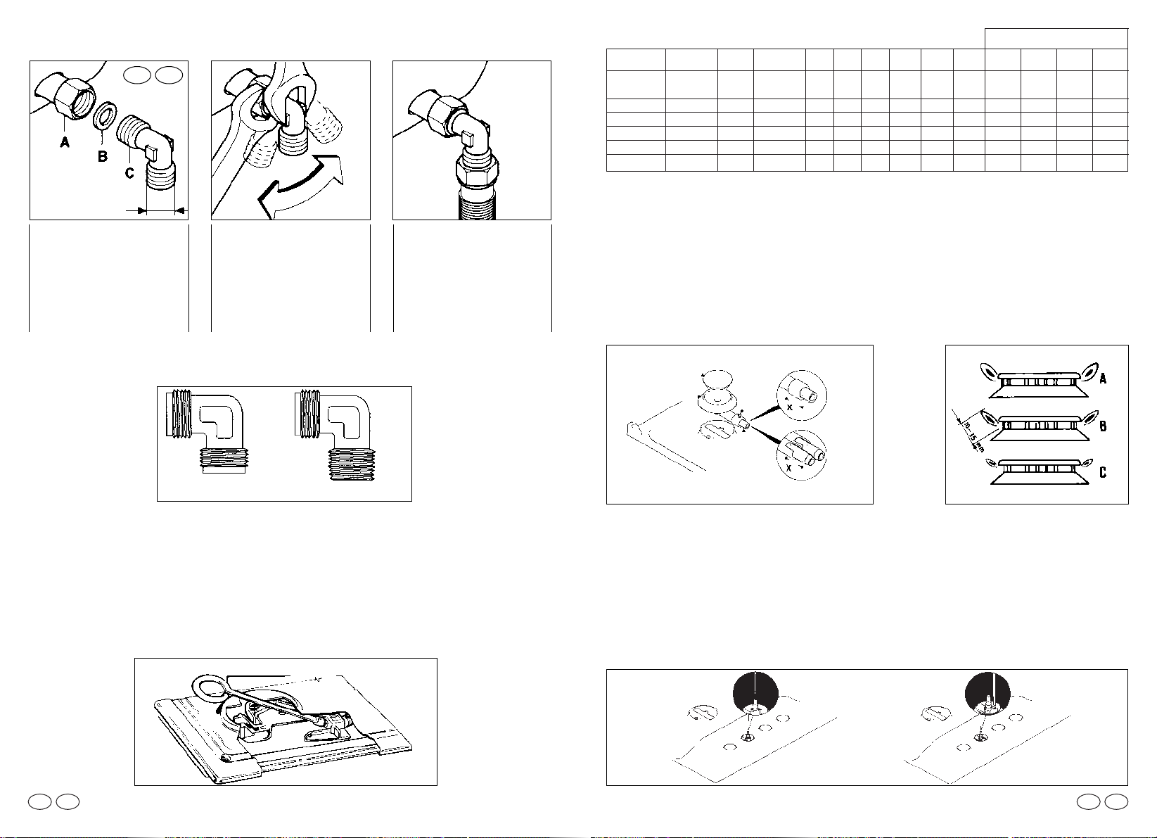
REGULATING THE MINIMUM FLAME
After lighting the burners, turn the control knob to the minimum setting and then remo-
ve the knob (this can easily be removed by apply a gentle pressure).
Using a small «Terminal» type screwdriver the regulating screw can be adjusted as in
Fig. 9. Turning the screw clockwise reduces the gas flow, whilst turning it anticlockwise
increases the flow – Use this adjustment to obtain a flame of approximately 3 to 4 mm
in length and then replace the control knob.
When the gas supply available is LPG (Bottle gas)- the screw to set the idle flame must
be turned (clockwise) to the end stop.
Screws regulating
(for differend models)
42
Fig. 9
Fig. 7 Fig. 8
BURNER
BURNER CAP
AIR REGULATION
SCREW
FIXING
SCREW
SMALL
MEDIUM
LARGE
DOUBLE RING
MAXI
FISH
For dimensions «X» see table of gas consumption
SETTING OF THE GAS BURNERS
When the jets have been changed it is necessary to set the correct air gap by keeping
to the setting “X” as shown in the table “ gas consumption” fig 7. Warning the value of ‘
X ‘ setting varies in relation to the size of gas burner and type of gas chosen.
A good flame must be of medium length (fig.8B), excessive air will cause the flame to
be short and with sharp colour (fig.8C): in this case it is necessary to extend out the tu-
be for the air setting from the burner body, if there is insufficient air the flame will ap-
pear weak and long (fig. 8A): in this case push the tube of the air setting back into the
burner body. To adjust the air setting tube loosen the retaining screw.
Once the air is correctly set secure the screw over the tube ( fig. 7).
41
ADAPTING THE HOB TO DIFFERENT TYPES OF GAS
To adapt the Hob for use with different types of gas, carry out the following instructions:
— remove the grids and burners
— insert the hexagonal spanner (supplied) into the burner support (Fig. 6)
— unscrew the injector and replace it with one suitable for the gas to be used (see
Table of gas consumption)
— carry out regulation of the burner.
1/2 GAS
CONICAL
A) As illustrated, as-
semble parts in se-
quence:
A) fixed pipe
B) washer
C) Elbow fitting with
tapered thred
connection
2) Tighten the joints
with the Spanners,
remembering to twist
the pipes into position.
3) Attach fitting C to
mains gas supply us-
ing rigid copper pipe
or flexible steel pipe.
IEGB
Please note
Some models are equipped with both conical and cylindrical connectors for gas supply.
Please select the type which is correct for the supply concerned.
To prevent any potential damage to the hob please carry out the installation following
this sequence:
Fig. 5
AB
Hexagonal spanner
Fig. 6
Cylindrical
(but connector)
Tapered thread conical
GB IE GBIE
reg.
air
4mm
2mm
15 mm
13 mm
15 mm
Working
burner
large
medium
maxi
double ring
fish
Ø gas jet
1/100 mm
120
93
2x94
2x94
2x94
Ø gas jet
1/100 mm
80
61
2x65
2x65
2x65
STD. Dim
kW
2,65
1,5
3,3
3,3
3,3
l/h
G20
252
143
314
314
314
g/h
G30
193
109
238
238
238
g/h
G31
189
107
236
236
236
Qn
kW
2,5
1,45
3,1
3,1
3,1
l/h
G25
277
161
343
343
343
min.Dim
kW
0,65
0,38
0,9
0,9
0,9
reg.
air
4mm
2mm
15 mm
13 mm
15 mm
reg.
air
2mm
5mm
0 mm
0 mm
0 mm
G20 G30 G25 G31
G30
G31
G20/G25
G20 20mbar
G30 29mbar
G31 37mbar
G25
25mbar
X dimension according
to Gas type
Table of gas consumption 1W = 0,860 kcal/h
reg.
air
5mm
7mm
15 mm
15 mm
15 mm
Loading ...
Loading ...
Loading ...