
User Guide
Gigabit Easy Smart Switch
TL-SG1016DE/TL-SG1024DE/TL-SG1016PE
TL-SG105E/TL-SG108E/TL-SG108PE
REV3.1.0
1910011971

COPYRIGHT & TRADEMARKS
Specifications are subject to change without notice. is a registered trademark of
TP-Link Technologies Co., Ltd. Other brands and product names are trademarks or registered
trademarks of their respective holders.
No part of the specifications may be reproduced in any form or by any means or used to make
any derivative such as translation, transformation, or adaptation without permission from
TP-Link Technologies Co., Ltd. Copyright © 2016 TP-Link Technologies Co., Ltd. All rights
reserved.
http://www.tp-link.com
FCC STATEMENT (For TL-SG105E/TL-SG108E/TL-SG108PE only)
This equipment has been tested and found to comply with the limits for a Class B digital device,
pursuant to part 15 of the FCC Rules. These limits are designed to provide reasonable
protection against harmful interference in a residential installation. This equipment generates,
uses and can radiate radio frequency energy and, if not installed and used in accordance with
the instructions, may cause harmful interference to radio communications. However, there is
no guarantee that interference will not occur in a particular installation. If this equipment does
cause harmful interference to radio or television reception, which can be determined by turning
the equipment off and on, the user is encouraged to try to correct the interference by one or
more of the following measures:
• Reorient or relocate the receiving antenna.
• Increase the separation between the equipment and receiver.
• Connect the equipment into an outlet on a circuit different from that to which the receiver
is connected.
• Consult the dealer or an experienced radio/ TV technician for help.
This device complies with part 15 of the FCC Rules. Operation is subject to the following two
conditions:
1) This device may not cause harmful interference.
2) This device must accept any interference received, including interference that may cause
undesired operation.
Any changes or modifications not expressly approved by the party responsible for compliance
could void the user’s authority to operate the equipment.
I

FCC STATEMENT (For TL-SG1016DE/TL-SG1024DE/TL-SG1016PE only)
This equipment has been tested and found to comply with the limits for a Class A digital device,
pursuant to part 15 of the FCC Rules. These limits are designed to provide reasonable
protection against harmful interference when the equipment is operated in a commercial
environment. This equipment generates, uses, and can radiate radio frequency energy and, if
not installed and used in accordance with the instruction manual, may cause harmful
interference to radio communications. Operation of this equipment in a residential area is likely
to cause harmful interference in which case the user will be required to correct the interference
at his own expense.
This device complies with part 15 of the FCC Rules. Operation is subject to the following two
conditions:
1) This device may not cause harmful interference.
2) This device must accept any interference received, including interference that may cause
undesired operation.
Any changes or modifications not expressly approved by the party responsible for compliance
could void the user’s authority to operate the equipment.
CE Mark Warning (For TL-SG105E/TL-SG108E/TL-SG108PE only)
This is a class B product. In a domestic environment, this product may cause radio interference,
in which case the user may be required to take adequate measures.
CE Mark Warning (For TL-SG1016DE/TL-SG1024DE/TL-SG1016PE only)
This is a class A product. In a domestic environment, this product may cause radio interference,
in which case the user may be required to take adequate measures.
Industry Canada Statement (For TL-SG105E/TL-SG108E/TL-SG108PE only)
CAN ICES-3 (B)/NMB-3(B)
Industry Canada Statement (For TL-SG1016DE/TL-SG1024DE/TL-SG1016PE
only)
CAN ICES-3 (A)/NMB-3(A)
II

RECYCLING
This product bears the selective sorting symbol for Waste electrical and electronic
equipment (WEEE). This means that this product must be handled pursuant to
European directive 2012/19/EU in order to be recycled or dismantled to minimize
its impact on the environment.
User has the choice to give his product to a competent recycling organization or to
the retailer when he buys a new electrical or electronic equipment.
IV

CONTENTS
Package Contents ......................................................................................................................... 1
Chapter 1 About this Guide .......................................................................................................... 2
1.1 Intended Readers ......................................................................................................... 2
1.2 Conventions ................................................................................................................. 2
1.3 Overview of This Guide ................................................................................................ 3
Chapter 2 Introduction ................................................................................................................. 5
2.1 Overview of the Switch ................................................................................................ 5
2.2 Appearance Description .............................................................................................. 5
2.2.1 Front Panel ........................................................................................................ 5
2.2.2 Rear Panel ......................................................................................................... 9
Chapter 3 Login to the Switch .................................................................................................... 11
3.1 Login .......................................................................................................................... 11
3.2 Configuration ............................................................................................................. 12
Chapter 4 System ....................................................................................................................... 13
4.1 System Info ................................................................................................................ 13
4.2 IP Setting .................................................................................................................... 13
4.3 User Account ............................................................................................................. 14
4.4 System Tools ............................................................................................................. 15
4.4.1 Backup and Restore ........................................................................................ 15
4.4.2 System Reboot ................................................................................................ 17
4.4.3 System Reset .................................................................................................. 17
4.4.4 Firmware Upgrade ........................................................................................... 18
Chapter 5 Switching ................................................................................................................... 20
5.1 Port Setting ................................................................................................................ 20
5.2 IGMP Snooping .......................................................................................................... 21
5.3 LAG ............................................................................................................................. 22
Chapter 6 Monitoring ................................................................................................................. 24
6.1 Port Statistics ............................................................................................................. 24
6.2 Port Mirror .................................................................................................................. 25
6.3 Cable Test .................................................................................................................. 26
6.4 Loop Prevention ......................................................................................................... 27
Chapter 7 VLAN .......................................................................................................................... 28
7.1 MTU VLAN .................................................................................................................. 29
7.2 Port Based VLAN........................................................................................................ 30

7.3 802.1Q VLAN ............................................................................................................. 31
7.4 802.1Q PVID Setting .................................................................................................. 32
Chapter 8 QoS ............................................................................................................................ 34
8.1 QoS Basic ................................................................................................................... 36
8.2 Bandwidth Control ..................................................................................................... 38
8.3 Storm Control ............................................................................................................ 38
Chapter 9 PoE ............................................................................................................................ 40
9.1 PoE Config ................................................................................................................. 41
Appendix A: Specifications .......................................................................................................... 43

Package Contents
The following items should be found in your box:
One Gigabit Easy Smart Switch
One power cord
Two mounting brackets and other fittings (for TL-SG1016DE/TL-SG1024DE/
TL-SG1016PE only)
Installation Guide
Resource CD for TL-SG105E/TL-SG108E/TL-SG108PE/TL-SG1016DE/TL-SG1024DE/
TL-SG1016PE switch, including:
• This User Guide
• Easy Smart Configuration Utility.exe
• Easy Smart Configuration Utility User Guide
• Other Helpful Information
Note:
Make sure that the package contains the above items. If any of the listed items are damaged or
missing, please contact your distributor.
1

Chapter 1 About this Guide
This User Guide contains information for setup and management of TL-SG105E/TL-SG108E/
TL-SG108PE/TL-SG1016DE/TL-SG1024DE/TL-SG1016PE Gigabit Easy Smart Switch. Please
read this guide carefully before operation.
1.1 Intended Readers
This Guide is intended for network managers familiar with IT concepts and network
terminologies.
1.2 Conventions
When using this guide, please notice that features of the switch may vary slightly depending on
the model and software version you have, and on your location, language, and Internet service
provider. All screenshots, images, parameters and descriptions documented in this guide are
used for demonstration only.
The information in this document is subject to change without notice. Every effort has been
made in the preparation of this document to ensure accuracy of the contents, but all
statements, information, and recommendations in this document do not constitute the
warranty of any kind, express or implied. Users must take full responsibility for their application
of any products.
In this Guide the following conventions are used:
The switch or TL-SG105E/TL-SG108E/TL-SG108PE/TL-SG1016DE/TL-SG1024DE/
TL-SG1016PE mentioned in this Guide stands for TL-SG105E/TL-SG108E/TL-SG108PE/
TL-SG1016DE/TL-SG1024DE/TL-SG1016PE Gigabit Easy Smart Switch without any
explanation.
Menu Name→Submenu Name→Tab page indicates the menu structure. System→System
Info→System Summary means the System Summary page under the System Info menu
option that is located under the System menu.
Bold font indicates a button, a toolbar icon, menu or menu item.
Symbols in this Guide:
Symbol
Description
Note:
Ignoring this type of note might result in a malfunction or damage to the device.
Tips:
This format indicates important information that helps you
make better use of
your device.
2

More Info:
The latest software, management app and utility can be found at Download Center at
http://www.tp-link.com/support.
The Installation Guide (IG) can be found where you find this guide or inside the package of
the switch.
Specifications can be found on the product page at
http://www.tp-link.com.
A Technical Support Forum is provided for you to discuss our products at
http://forum.tp-link.com
.
Our Technical Support contact information can be found at the Contact Technical Support
page at
http://www.tp-link.com/support
.
1.3 Overview of This Guide
Chapter
Introduction
Chapter 1 About This
Guide
Introduces the guide structure and conventions.
Chapter 2 Introduction
Introduces the features, application and appearance of
TL-SG105E/TL-SG108E/TL-SG108PE/TL-SG1016DE/
TL-SG1024DE/TL-SG1016PE switch.
Chapter 3 Login to the
Switch
Introduces how to log on to the Web management page.
Chapter 4 System This module is used to configure system properties of the
switch. Here mainly introduces:
System Info: View device information and define the device
description.
IP Setting: Get and modify the network parameters of the
switch.
User Account: Modify the username and password for users
to log on to the Web management page.
System Tools: Manage the configuration file of the switch.
Chapter 5 Switching
Configure the basic functions of the switch.
Chapter 6 Monitoring Monitor the traffic information of the switch, and provide the
convenient method to locate and solve the network problem.
Chapter 7 VLAN This module is used to configure VLANs to control broadcast in
LANs. Here mainly introduces:
MTU VLAN: Set the MTU VLAN mode.
Port Based VLAN: Set the Port-Based VLAN mode
802.1Q VLAN: Set the 802.1Q Tag VLAN mode.
802.1Q PVID Setting: Configure 802.1Q PVID value.
3

Chapter
Introduction
Chapter 8 QoS
This module is used to configure QoS function to provide
different quality of service for various network applications and
requirements. Here mainly introduces:
QoS Basic: Configure and view the basic parameters of QoS.
Bandwidth Control:
Configure and view the bandwidth
control function information.
Storm Control: Configure and view the storm control function
information.
Chapter 9 PoE
This module is used to configure the PoE function for the switch to
supply power for PD devices.
Appendix A Specifications
Lists the hardware specifications of the switch.
Return to CONTENTS
4
Chapter 2 Introduction
Thanks for choosing the TL-SG105E/TL-SG108E/TL-SG108PE/TL-SG1016DE/TL-SG1024DE/
TL-SG1016PE Gigabit Easy Smart Switch!
2.1 Overview of the Switch
The TL-SG105E/TL-SG108E/TL-SG108PE/TL-SG1016DE/TL-SG1024DE/TL-SG1016PE Gigabit
Easy Smart Switch
is an ideal upgrade from an unmanaged switch, designed for Small and
Medium Business networks that require simple network management. Network administrators
can effectively monitor traffic via Port Mirroring, Loop Prevention and Cable Test features. To
optimize traffic on your business network, they offer port-based, tag-based, DSCP-based QoS
to keep latency-sensitive traffic moving smoothly and jitter-free. Additionally, port-based,
tag-based and MTU VLAN can improve security and meet more network segmentation
requirements. Moreover, with the innovative energy-efficient technology, they are eco-friendly
solution for your business network.
Note:
For details about Easy Smart Configuration Utility, please refer to the User Guide of the Easy
Smart Configuration Utility in the Resource CD.
2.2 Appearance Description
2.2.1 Front Panel
TL-SG105E/TL-SG108E
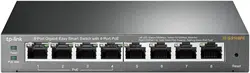
The front panel of TL-SG105E is shown as Figure 2-1.
Figure 2-1 Front Panel of
TL-SG105E
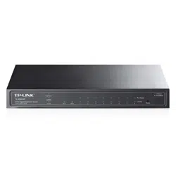
The front panel of TL-SG108E is shown as Figure 2-2.
Figure 2-2 Front Panel of
TL-SG108E
The following parts are located on the front panel of the switch:
Reset: With the switch powered on, press this button for five seconds or above to reset the
software setting back to factory default setting. (For TL-SG108E only)
5
1000Mbps Ports: Designed to connect to the device with a bandwidth of 10Mbps, 100Mbps
or 1000Mbps. Each has a corresponding 1000Mbps LED and 10/100Mbps LED.
LEDs
Name
Status
Indication
Power
On
Power is on.
Flashing
Power supply is abnormal.
Off
Power is off or power supply is abnormal.
1000Mbps
On
A 1000Mbps device is connected to the corresponding port.
Flashing
Data is being transmitted or received.
Off
A 10/100Mbps device or no device is connected to the
corresponding port.
10/100Mbps
On
A 10/100Mbps device is connected to the corresponding port.
Flashing
Data is being transmitted or received.
Off
No device is connected to the corresponding port.
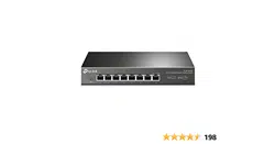
TL-SG108PE
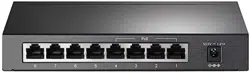
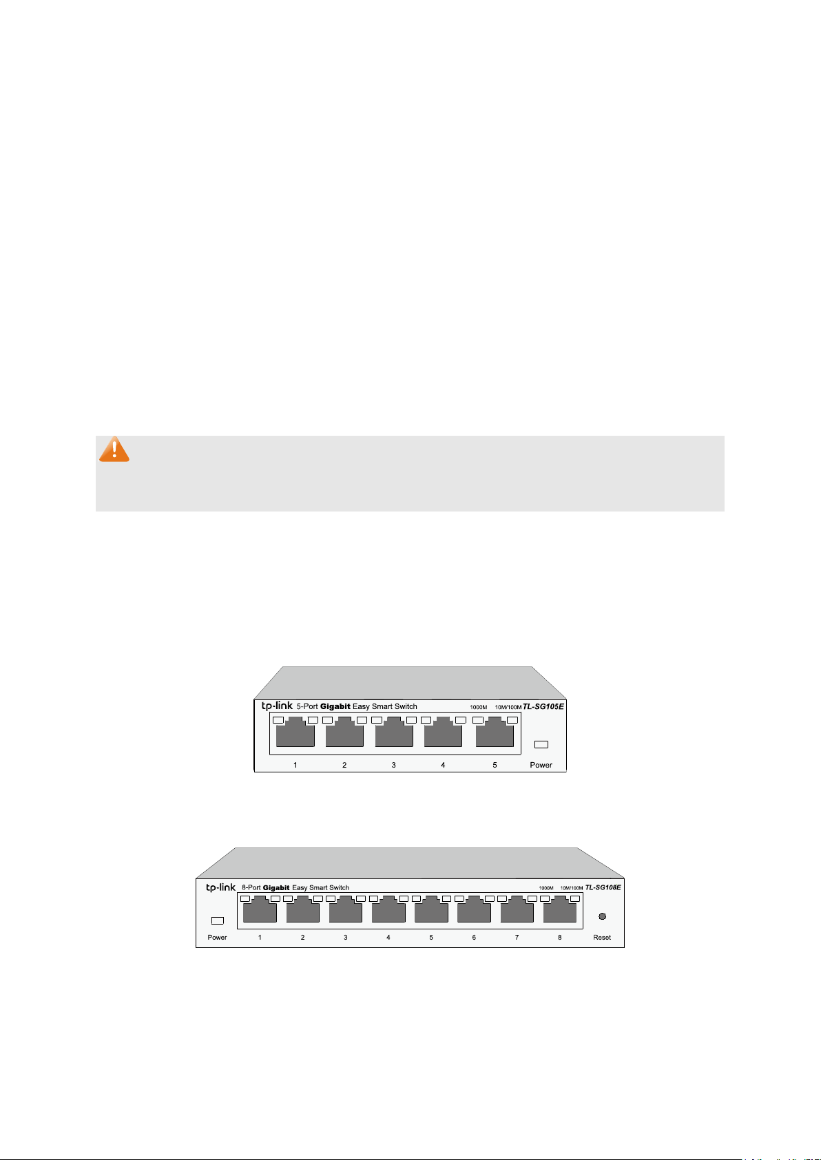
The front panel of TL-SG108PE is shown as Figure 2-3.
Figure 2-3 Front Panel of
TL-SG108PE
The following parts are located on the front panel of the switch:
Reset: With the switch powered on, press this button for five seconds or above to reset the
software setting back to factory default setting.
1000Mbps Ports: Designed to connect to the device with a bandwidth of 10Mbps, 100Mbps
or 1000Mbps. Each has a corresponding Link/Act LED (Left LED). For Port 1– 4, each of
them also has a PoE Status LED (Right LED).
LEDs
Name
Status
Indication
Power
On
Power is on.
Flashing
Power supply is abnormal.
Off
Power is off or power supply is abnormal.
PoE Max
On
46W≤ The total power supply< 55W.
Flashing
The total power supply≥ 55W.
Off
The total power supply< 46W.
6
Link/Act
On(Green)
A 1000Mbps device is connected to the corresponding port.
On(Yellow)
A 10/100Mbps device is connected to the corresponding
port.
Flashing
Data is being transmitted or received.
Off
No device is connected to the corresponding port.
PoE Status
On
The port is supplying power normally.
Flashing
The port is supplying power abnormally.
Off
No PoE power supply is provided on the port.
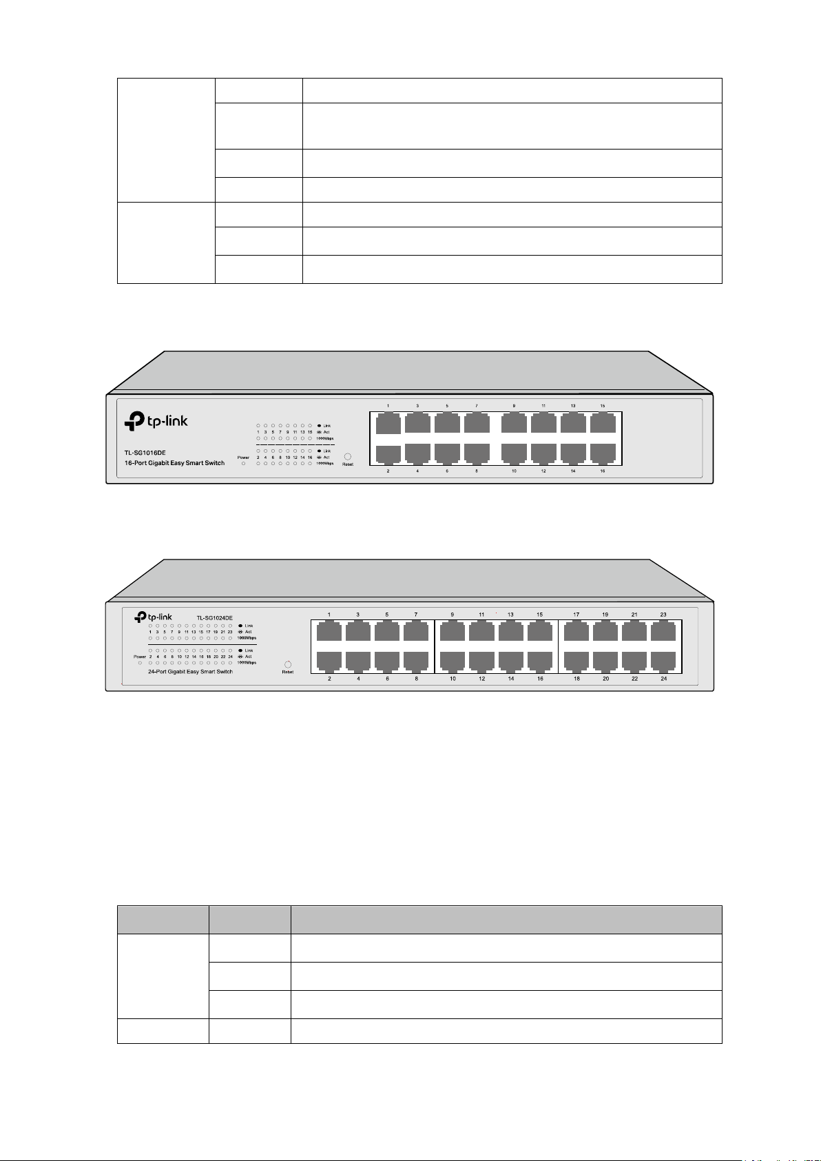
TL-SG1016DE/TL-SG1024DE
The front panel of TL-SG1016DE is shown as Figure 2-4.
Figure 2-4 Front Panel of TL-SG1016DE
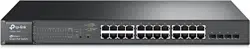
The front panel of TL-SG1024DE is shown as Figure 2-5.
Figure 2-5 Front Panel of TL-SG1024DE
The following parts are located on the front panel of the switch:
Reset: With the switch powered on, press this button for five seconds or above to reset the
software setting back to factory default setting.
1000Mbps Ports: Designed to connect to the device with a bandwidth of 10Mbps, 100Mbps
or 1000Mbps. Each has a corresponding 1000Mbps LED and Link/Act LED.
LEDs
Name
Status
Indication
Power
On
Power is on.
Flashing
Power supply is abnormal.
Off
Power is off or power supply is abnormal.
1000Mbps
On
A 1000Mbps device is connected to the corresponding port.
7

PoE Max
On
The power of all the connected PoE ports is between
103W and 110W. No power may be supplied if additional
PDs are connected.
Flashing
The power of all the connected PoE ports is ≥110W.
Off
The power of all the connected PoE ports is <103W.
FAN
Green
The fan works properly.
Yellow
The fan doesn't work properly.
2.2.2 Rear Panel
TL-SG105E/TL-SG108E/TL-SG108PE
The rear panel of TL-SG105E/TL-SG108E/TL-SG108PE features a power socket and a
Kensington Security Slot (marked with
). TL-SG105E also has a Reset button located on the
rear panel.
Figure 2-7 Rear Panel of TL-SG105E
Figure 2-8 Rear Panel of
TL-SG108E
Figure 2-9
Rear Panel of TL-SG108PE
Reset: With the switch powered on, press this button for five seconds or above to reset the
software setting back to factory default setting. (For TL-SG105E only)
Kensington Security Slot: Secure the lock (not provided) into the security slot to prevent
the device from being stolen.
DC Power Socket: Connect the female connector of the power cord here, and the male
connector to the DC power outlet. Please make sure the voltage of the power supply meets
the requirement of the input voltage.
9

TL-SG1016DE/TL-SG1024DE/TL-SG1016PE
The rear panel of TL-SG1016DE/TL-SG1024DE/TL-SG1016PE features a power socket and a
Grounding Terminal (marked with
). TL-SG1016PE also has a Kensington Security Slot
(marked with
) located on the rear panel.
Figure 2-10 Rear Panel of TL-SG1016DE
Figure 2-11 Rear Panel of TL-SG1024DE
Figure 2-12 Rear Panel of TL-SG1016PE
Grounding Terminal: TL-SG105E/TL-SG108E/TL-SG108PE/TL-SG1016DE/TL-SG1024DE/
TL-SG1016PE already comes with Lightning Protection Mechanism. You can also ground
the switch through the PE (Protecting Earth) cable of AC cord or with Ground Cable.
AC Power Socket: Connect the female connector of the power cord here, and the male
connector to the AC power outlet. Please make sure the voltage of the power supply meets
the requirement of the input voltage.
Kensington Security Slot: Secure the lock (not provided) into the security slot to prevent
the device from being stolen.
Return to CONTENTS
10

Chapter 3 Login to the Switch
3.1 Login
1) To access the configuration utility, open a web-browser and type the default address
http://192.168.0.1 in the address field of the browser, then press the Enter key.
Figure 3-1 Web-browser
Tips:
To log in to the switch, the IP address of your PC should be set in the same subnet addresses
of the switch. The IP address is 192.168.0.x ("x" is any number from 2 to 254), Subnet Mask is
255.255.255.0.
2) After a moment, a login window will appear, as shown in Figure 3-2. Enter admin for the User
Name and Password, both in lower case letters. Then click the Login button or press the
Enter key.
Figure 3-2 Login
11
3.2 Configuration
After a successful login, the main page will appear as Figure 3-3, and you can configure the
function by clicking the setup menu on the left side of the screen.
Figure 3-3 Main Setup-Menu
Note:
Clicking Apply can only make the new configurations effective before the switch is rebooted. If
you want to keep the configurations effective even the switch is rebooted, please click Save
Config. You are suggested to click Save Config before cutting off the power or rebooting the
switch to avoid losing the new configurations.
Return to CONTENTS
12

Chapter 4 System
The System module is mainly for basic settings of the switch, including four submenus: System
Info, IP Setting, User Account and System Tools.
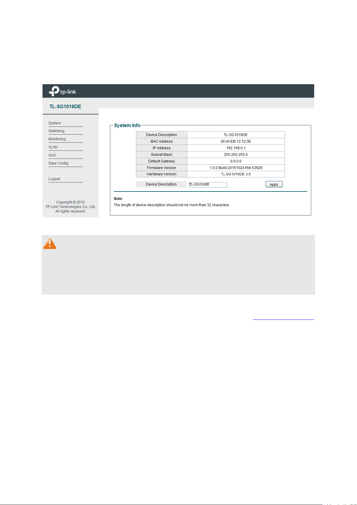
4.1 System Info
On this page you can view the system information and define the device description.
Choose the menu System→System Info to load the following page.
Figure 4-1 System Info
The following entries are displayed on this screen:
System Info
Device Description:
Displays the device model number.
MAC Address:
Displays the MAC address of the switch.
IP Address: Displays the system IP a
ddress of the switch. The default
system IP is 192.168.0.1 and you can change it appropriate to
your needs.
Subnet Mask:
Displays the subnet mask of the switch.
Default Gateway:
Displays the default gateway of the switch.
Firmware Version:
Displays the installed software version number.
Hardware Version:
Displays the installed device hardware version number.
Device Description:
Give a description to the device for identification.
4.2 IP Setting
Each device in the network possesses a unique IP Address. You can log on to the Web
management page to operate the switch using this IP Address.
13
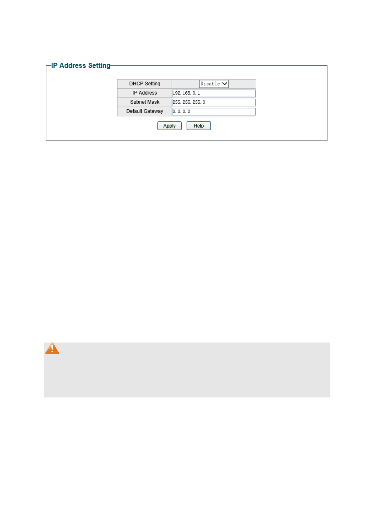
On this page you can get and modify the network parameters of the switch.
Choose the menu System→IP Setting to load the following page.
Figure 4-2 IP Address Setting
The following entries are displayed on this screen:
IP Address Setting
DHCP Setting: Allows you to enable or disable the switch to serve as
DHCP
client. If DHCP client is enabled, the switch will obtain the IP
address, subnet mask and
default gateway from the DHCP
s
erver automatically; otherwise, these three items should be
configured manually. By default, it is disabled.
IP Address: Specify the system IP a
ddress of the switch. The default system
IP address
is 192.168.0.1 and you can change it appropriate to
your needs.
The switch IP address must be compliant with the
subnet layout.
Subnet Mask: Enter the subnet mask of the switch. Subnet mask is a
n address
code that determines the size of the network.
By default, the
switch uses 255.255.255.0 as the subnet mask.
Default Gateway: Enter the default gateway of the switch.
Gateway serves as the
default destination where the packet is to be forwa
rded when its
destination IP address is not within the switch’s subnet.
Note:
1. The switch only possesses an IP address. The IP address newly configured will replace the
original one.
2. Changing the IP address to a different IP segment will interrupt the network communication,
so please keep the new IP address in the same IP segment with the local network.
4.3 User Account
On this page you can modify the username and password in order to refuse illegal users.
Choose the menu System→User Account to load the following page.
14

Figure 4-3 User Account Setting
You are kindly suggested to retype the new password in "Confirm Password" box instead of
copying in order to avoid mistakes.
Note:
1. The length of user name and password should not be more than 16 characters using digits,
English letters and underlines only.
2. The default username/password is admin/admin.
4.4 System Tools
The System Tools function, allowing you to manage the configuration file of the switch, can be
implemented on Backup and Restore, System Reboot, System Reset and Firmware Upgrade
pages.
4.4.1 Backup and Restore
On this page you can download the current configuration and save it as a file to your computer
for your future configuration to upload a backup configuration file to restore your switch to this
previous configuration.
Choose the menu System→System Tools→Backup and Restore to load the following page.
15

Figure 4-4 Backup and Restore
The following entries are displayed on this screen:
Config Backup
Backup Config: Click the Backup Config
button to save the current
configuration as a file to your computer. You are suggested to
take this measure before upgrading.
Config Restore
Restore Config: Click the Restore Config but
ton to restore the backup
configuration file. It will take effect after the switch automatically
reboots.
Note:
1. It will take several minutes to backup or restore the configuration file. Please wait without
any operation.
2. To avoid any damage, please don’t power down the switch while being restored.
3. After being restored, the current settings of the switch will be lost. Wrong uploaded
configuration file may cause the switch unmanaged.
16
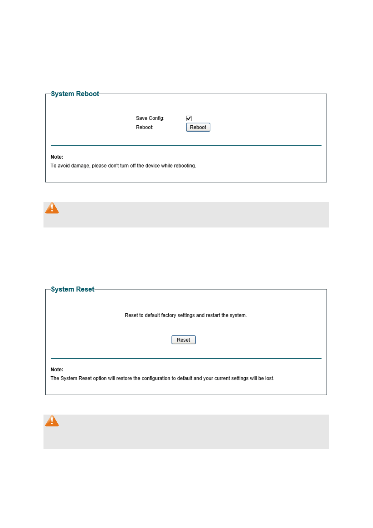
4.4.2 System Reboot
On this page you can reboot the switch and return to the login page. Please save the current
configuration before rebooting to avoid losing the configuration unsaved.
Choose the menu System→System Tools→System Reboot to load the following page.
Figure 4-5 System Reboot
Note:
To avoid damage, please don't turn off the device while rebooting.
4.4.3 System Reset
On this page you can reset the switch to the default. All the settings will be cleared after the
switch is reset.
Choose the menu System→System Tools→System Reset to load the following page.
Figure 4-6 System Reset
Note:
The System Reset option will restore the configuration to default and your current settings will
be lost.
17

4.4.4 Firmware Upgrade
The switch system can be upgraded via the Web management page. To upgrade the system is
to get more functions and better performance. Go to http://www.tp-link.com
to download the
updated firmware.
Choose the menu System→System Tools→Firmware Upgrade to load the following page.
Figure 4-7 Firmware Upgrade
Click Ready and the following page will appear.
Figure 4-8 Select the Firmware
The following entries are displayed on this screen:
Upgurade
Upgrade:
Click the Upgrade button to upgrade the firmware of the switch.
Abort:
Click the Abort button to stop the process of upgrade.
Note:
1. Don’t interrupt the upgrade.
18

2. You are suggested to backup the configuration before upgrading.
3. Please select the proper software version matching with your hardware to upgrade.
4. To avoid damage, please don't turn off the device while upgrading.
5. After upgrading, the device will reboot automatically.
Return to CONTENTS
19
Chapter 5 Switching
Switching module is used to configure the basic functions of the switch, including three
submenus: Port Setting, IGMP Snooping and LAG.
5.1 Port Setting
On this page, you can configure and view the basic parameters of each port, including the port
status, speed, duplex mode and flow control. As the parameters will affect the working mode of
the port, please set the parameters appropriate to your needs.
Choose the menu Switching→Port Setting to load the following page.
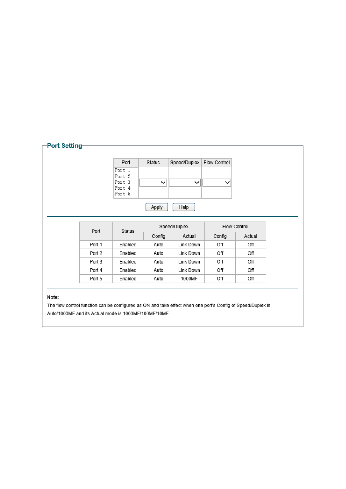
Figure 5-1 Port Setting
The following entries are displayed on this screen:
Port Setting
Port:
Select the desired port for configuration. It is multi-optional.
Status: Allows you to enable or
disable the port. “Enable" indicates that
the port is operational and "Disable" indicates the port is
non-
operational. If a port is unused for a long time, its status can
be set to “Disable” to cut down the energy cost.
20

Speed/Duplex: Select the Speed and Duplex mode for the port.
The device
connected to the switch should be in the same Speed and
Duplex mode with the switch.
Available field values are “Auto”,
“10M HD”, “10M FD”, “100M HD”, “100M FD” and “1000M FD”.
"HD" stands for Half-Duplex and "FD" stands for Full-
Duplex.
"Auto" means auto negotiation.
Flow Control:
Allows you to On/Off the Flow Control feature. When “On” is
selected, the switch can synchronize the speed with its peer to
avoid the packet loss caused by congestion.
Note:
The switch cannot be managed through the disabled port. Please enable the port which is used
to manage the switch.
5.2 IGMP Snooping
Internet Group Management Protocol (IGMP) snooping is a multicast control mechanism, which
can be used on the switch for dynamic registration of the multicast group.
IGMP Snooping allows the switch to recognize the IGMP messages transmitted between
network stations or devices and an IGMP host. When receiving IGMP report message from the
IGMP host, the switch will add the port to the multicast address table; when listening to IGMP
leave message from the IGMP host, the switch will remove the port from the multicast address
table. By managing and controlling the multicast address table, the broadcasting of multicast
traffic can be effectively prevented in the network.
On this page you can enable IGMP Snooping feature, Report Message Suppression feature and
view the current IGMP Group information.
Choose the menu Switching→IGMP Snooping to load the following page.
Figure 5-2 IGMP Snooping
The following entries are displayed on this screen:
IGMP Snooping
IGMP Snooping:
Enable or disable IGMP snooping function globally on the switch.
Report Message
Suppression:
Enable or disable
Report Message Suppression function
globally. If this function is enabled, the first Report Message
from the listener will forward to the router ports while the
subsequent Report Message will be suppressed to reduce the
IGMP packets.
21

IP Address:
Displays the multicast IP address.
VLAN ID:
Displays the VLAN ID of the multicast group. If the packet does
not carry VLAN ID, then here displays the PVID of the port. All
port members of a multicast group should be divided to the
same VLAN, and have the same PVID.
Ports:
Displays the forwarding port list of the multicast group.
5.3 LAG
LAG is used to combine a number of ports together to make a single high-bandwidth data path,
which can highly extend the bandwidth. The bandwidth of the LAG is the sum of bandwidth of
its member ports.
There are some rules on using LAG:
For the member ports in a LAG group, their configuration of Port setting (Speed and
Duplex, Flow Control), QoS must be the same.
For the newly joined member ports in a LAG group, their default setting of Port setting
(Speed and Duplex, Flow Control), QoS will be configured the same as that of the first
member port in the LAG group.
The LAG member ports cannot be set as mirroring port.
Before setting the LAG, its member ports should be divided to the same VLAN, and have
the same PVID and drop the untagged packet rule. Change of the LAG setting will not
affect the VLAN setting.
If the LAG is needed, you are suggested to configure the LAG function here before configuring
the other functions for the member ports.
On this page, you can configure and view the information of the LAG group of the switch.
22

Choose the menu Switching→LAG to load the following page.
Figure 5-3 LAG Setting
Here you can configure and view the port parameters.
LAG Setting
Group ID:
Select an identified number for the trunk group from the
drop-down list.
Port: Select the port as the trunk group member. It is multi-optional
.
Clearing all the ports of the trunk group will delete this trunk
group.
Tips:
Calculate the bandwidth for a LAG group: If a LAG consists of the four ports whose
Speed/Duplex mode is 1000Mbps/Full Duplex, the whole bandwidth of the LAG group is up to
8000Mbps (2000Mbps * 4) because the bandwidth of each member port is 2000Mbps counting
the up-linked speed of 1000Mbps and the down-linked speed of 1000Mbps.
Return to CONTENTS
23

Chapter 6 Monitoring
Monitoring module monitors the traffic information of the switch, and provides the convenient
method to locate and solve the network problem, includes four submenus: Port Statistics, Port
Mirror, Cable Test and Loop Prevention.
6.1 Port Statistics
On this page you can view the statistic information of each port, which facilitates you to
monitor the traffic and locate faults promptly.
Choose the menu Monitoring→Port Statistics to load the following page.
Figure 6-1 Port Statistics Info
The following entries are displayed on this screen:
Port Statistics Info
Port:
Displays the port number of the switch.
Status:
Displays whether the port is enabled or disabled.
Link Status:
Displays whether the port is link up or link down.
TxGoodPkt:
Displays the number of good packets transmitted on the port.
The error packets are not counted in.
TxBadPkt:
Displays the number of error packets transmitted on the port.
RxGoodPkt:
Displays the number of good packets received on the port. The
error packets are not counted in.
RxBadPkt:
Displays the number of error packets received on the port.
Note:
1. The frames with more than 1518 bytes, less than 64 bytes or with bad Frame Check
Sequence (FCS) are recorded as BadPkts.
2. Because of the supporting feature of jumbo frame, the frames with more than 1518 bytes
and less than 10000 bytes will be recorded as GoodPkts and BadPkts at the same time,
and can be forwarded normally.
24
6.2 Port Mirror
Port mirror functions to monitor and mirror network traffic by forwarding copies of incoming
and outgoing packets from one/multiple ports (mirrored port) to a specific port (mirroring port).
Usually, the mirroring port is connected to a data diagnosis device, which is used to analyze the
mirrored packets for monitoring and troubleshooting the network.
Choose the menu Monitoring→Port Mirror to load the following page.
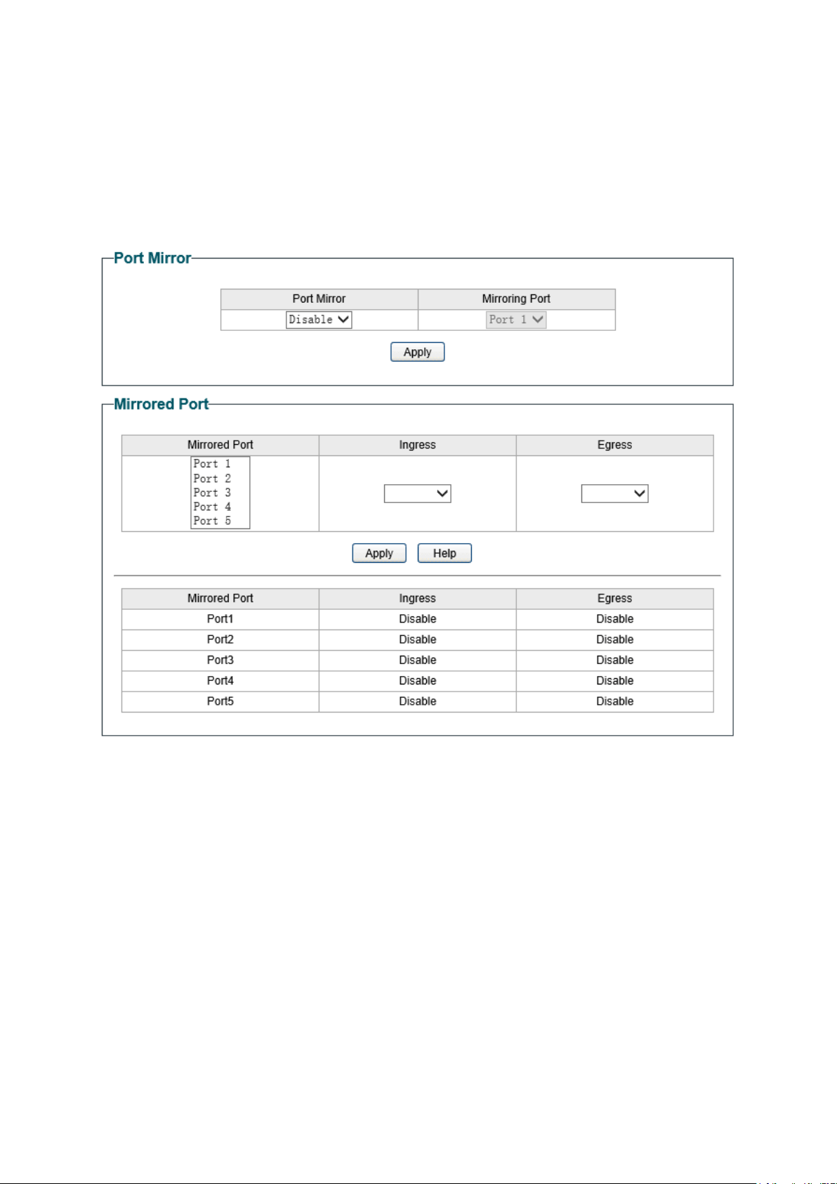
Figure 6-2 Port Mirror
The following entries are displayed on this screen:
Port Mirror
Port Mirror:
Allows you to enable or disable the port mirror feature of the
specified port.
Mirroring Port:
Select a port from the pull-down list as the mirroring port.
Mirrored Port
Mirrored Port: Select a port from the pull-down list as the mirrored port
to
monitor the traffic. LAG member cannot be defined here.
It is
multi-optional.
Ingress: Select whether to monitor the i
ngress traffic. When the ingress
is enabled, the ingress traffic received by the mirrored port will
be copied to the mirroring port.
25
Egress:
Select whether to monitor the egress traffic. When the egress is
enabled, the outgoing packets sent by the mirror
ed port will be
copied to the mirroring port.
Note:
1. The LAG member cannot be selected as the mirroring port.
2. A port cannot be set as the mirrored port and the mirroring port simultaneously.
3. The port mirror function can take effect span the multiple VLANs.
6.3 Cable Test
This switch provides cable test to diagnose the connection status of the cable connected to
the switch and the distance to the problem location, which facilitates you to locate and
diagnose the trouble spot of the network.
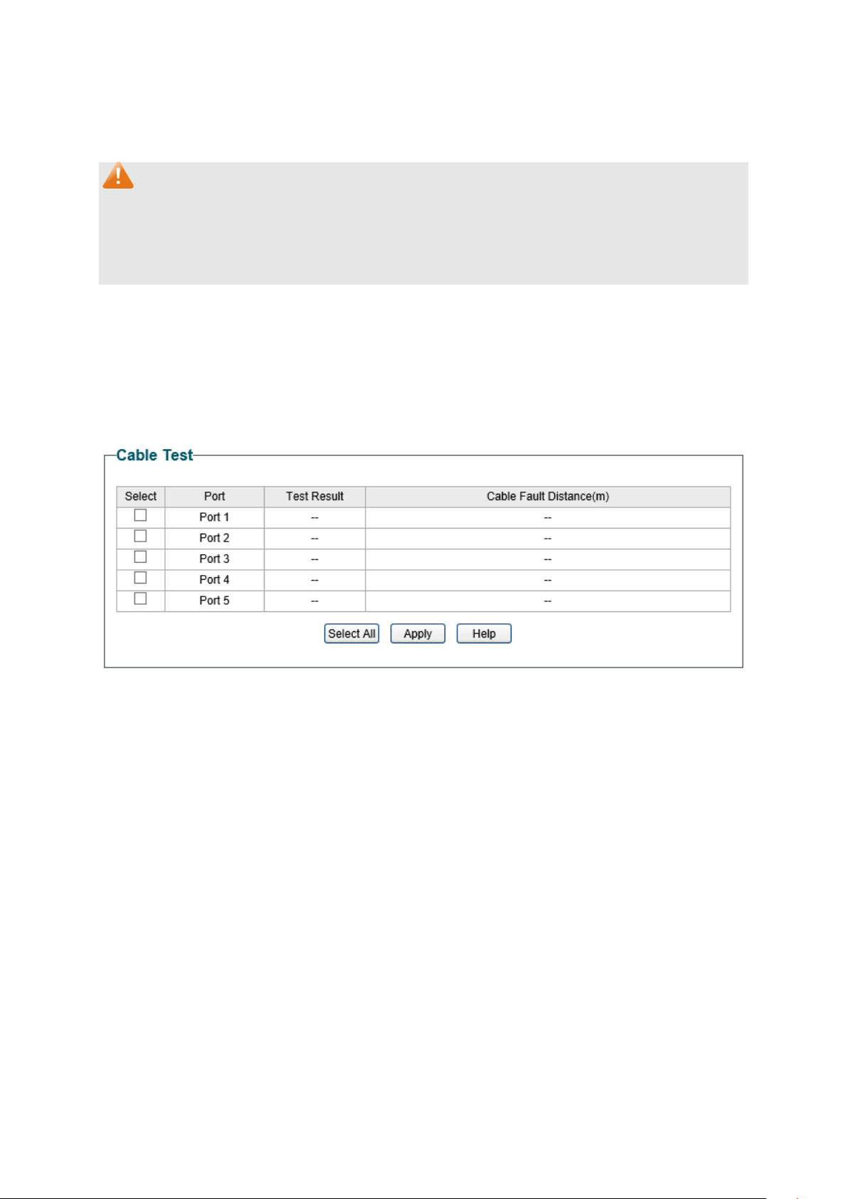
Choose the menu Monitoring→Cable Test to load the following page.
Figure 6-3 Cable Test
The following entries are displayed on this screen:
Cable Test
Select: Click the check box to select the desired port for cable test.
It is
multi-optional.
Port:
Displays the port number of the switch.
Test Result:
Displays the connection status of the cable connected to the
port. Test results include normal, short (or close)
, open and
crosstalk.
Normal : The cable is normally connected.
Short (or Close)
: A short circuit caused by an abnormal contact
of wires in the cable.
Open: No device is connected to the other end or the
connectivity is broken.
Crosstalk: Impedance mismatch caused by the poor quality of
the cable.
26
Cable Fault
Distance(m):
Displays the error length (in meters) of the cable.
Note:
The test result is just for your reference.
6.4 Loop Prevention
With loop prevention feature enabled, the switch can detect loops using loop detection
packets. When a loop is detected, the switch will block the corresponding port automatically.
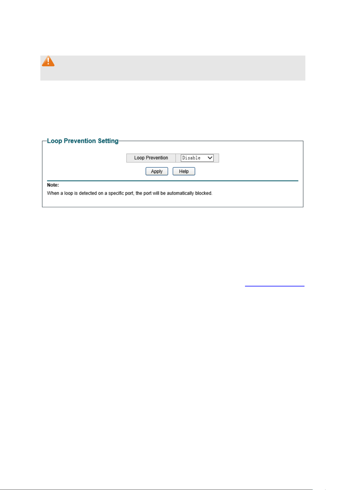
Choose the menu Monitoring→Loop Prevention to load the following page.
Figure 6-4 Loop Function Setting
The following entries are displayed on this screen:
Loop Prevention Setting
Loop Prevention:
Allows you to enable or disable loop prevention function globally.
Return to CONTENTS
27
There are 3 types of VLAN modes supported in the switch:
1. MTU VLAN
MTU VLAN (Multi-Tenant Unit VLAN) defines an uplink port which will build up several VLANs
with each of the other ports. Each VLAN contains two ports, the uplink port and one of the
other ports in the switch, so the uplink port can communicate with any other port but other
ports cannot communicate with each other.
2. Port Based VLAN
VLANs are divided based on ports. By default, the Port Based VLAN is enabled.
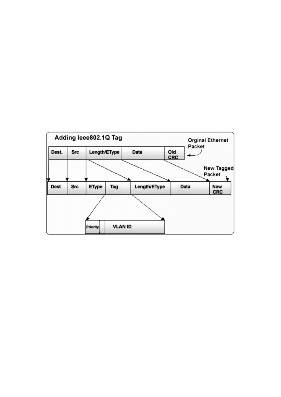
3. 802.1Q VLAN
The IEEE 802.1Q protocol defines a new format of the frame; it adds a Tag header in the original
Ethernet frame, as follows:
Figure 7-2 IEEE 802.1Q frame
VLAN tags in the packets are necessary for the switch to identify packets of different VLANs.
The switch works at the data link layer in OSI model and it can identify the data link layer
encapsulation of the packet only, so you can add the VLAN tag field into the data link layer
encapsulation for identification.
IEEE 802.1Q Tag VLAN is divided by VLAN ID (VID). On receiving a frame, the switch checks the
VID in the Tag header of the frame to decide which VLAN it belongs to. If the receiving frame
doesn’t contain the Tag header, the switch will assign a Tag to the frame, using the PVID of the
port as its VID.
In this User Guide, the tagged packet refers to the packet with VLAN tag whereas the untagged
packet refers to the packet without VLAN tag.
The VLAN module is mainly for VLAN configuration, including four submenus: MTU VLAN, Port
Based VLAN, 802.1Q VLAN and 802.1Q PVID Setting.
7.1 MTU VLAN
On this page you can choose to enable MTU VLAN mode and configure VLANs.
29
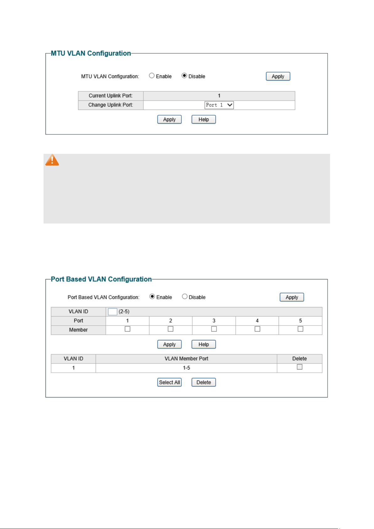
Choose the menu VLAN→MTU VLAN to load the following page.
Figure 7-3 MTU VLAN Configuration
Note:
1. The uplink port will form several VLANs with each of the other ports. Each VLAN contains
two ports, the uplink port and one of the other ports in the switch, thus the uplink port can
communicate with any other port but other ports cannot communicate with each other.
2. For the first time the MTU VLAN mode is enabled, the switch will set port 1 as the uplink
port by default.
7.2 Port Based VLAN
On this page you can configure Port Based VLAN feature and view the related settings.
Choose the menu VLAN→Port Based VLAN to load the following page.
Figure 7-4 Port Based VLAN Configuration
To ensure the normal communication of the factory switch, the default VLAN of all ports is set
to VLAN1. VLAN 1 cannot be deleted.
The following entries are displayed on this screen:
Port Based VLAN Configuration
Port Based VLAN
Configuration:
Enable or disable Port Based VLAN mode.
30
VLAN ID:
Enter the ID number of VLAN. It ranges from 2 to 32.
Port:
Displays the port number.
Member:
Click the check box to select the port of the
VLAN. It is
multi-optional.
If this field is checked, it indicates the port
belongs to the current VLAN.
Note:
A VLAN cannot be the subset or superset of the other VLANs.
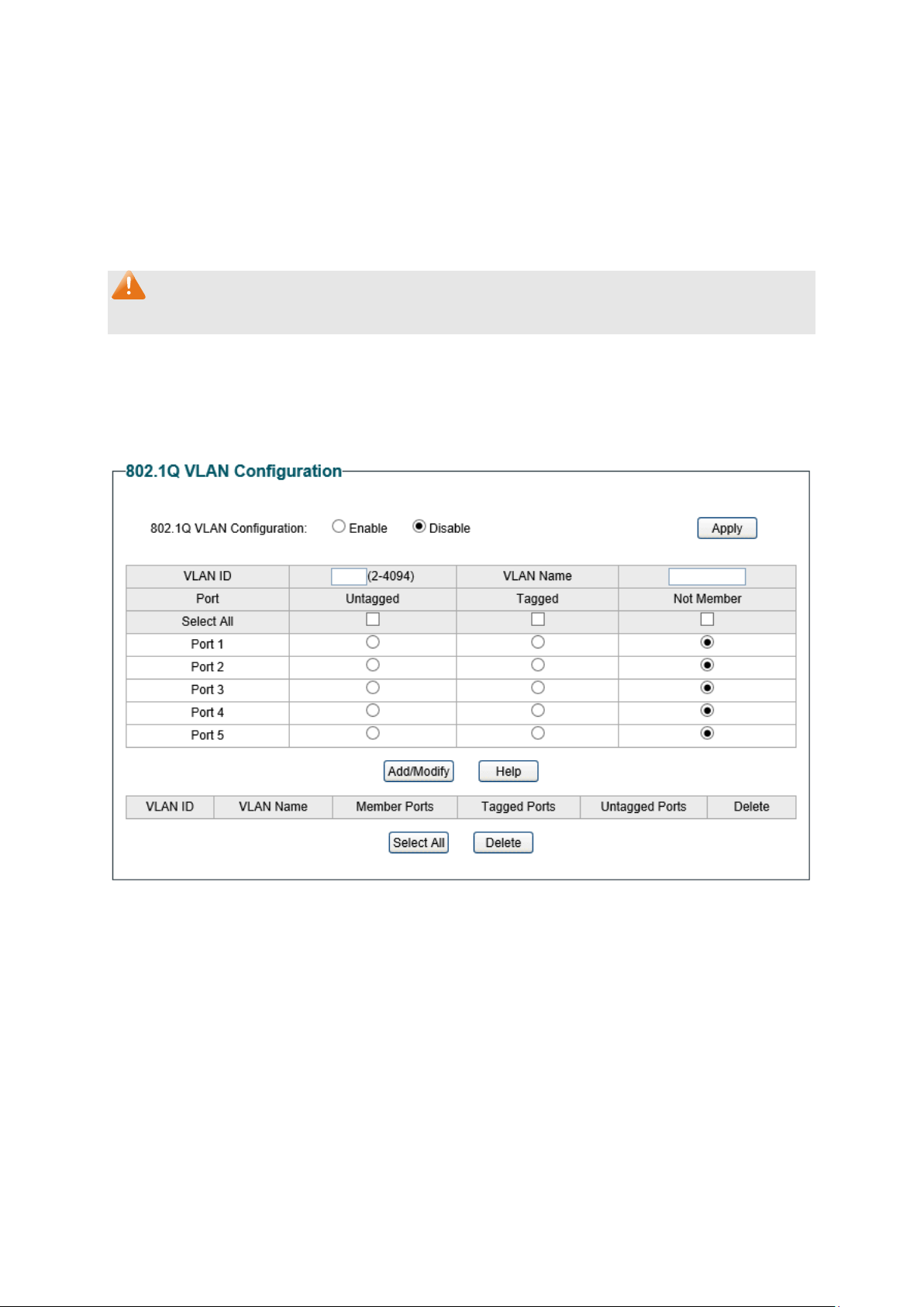
7.3 802.1Q VLAN
On this page you can configure 802.1Q VLAN feature and view the related settings.
Choose the menu VLAN→802.1Q VLAN to load the following page.
Figure 7-5 802.1Q VLAN Configuration
To ensure the normal communication of the factory switch, the default VLAN of all ports is set
to be VLAN1. VLAN 1 cannot be modified or deleted.
The following entries are displayed on this screen:
802.1Q VLAN Configuration
802.1Q VLAN
Configuration:
Enable or disable 802.1Q VLAN mode.
VLAN ID:
Enter the ID number of VLAN. It ranges from 2 to 4094.
VLAN Name:
Give a name to the VLAN for identification.
31
Port:
Displays the port number.
Untagged
:
Click the check box to configure the egress rule of the traffic
on this port as untagged. The switch dro
ps the tag header
before sending the packet.
Tagged:
Click the check box to configure the egress rule of the traffic
on this port as tagged. The switch adds the tag header before
sending the packet.
Not Member:
Click the check box to exclude the port from the current VLAN.
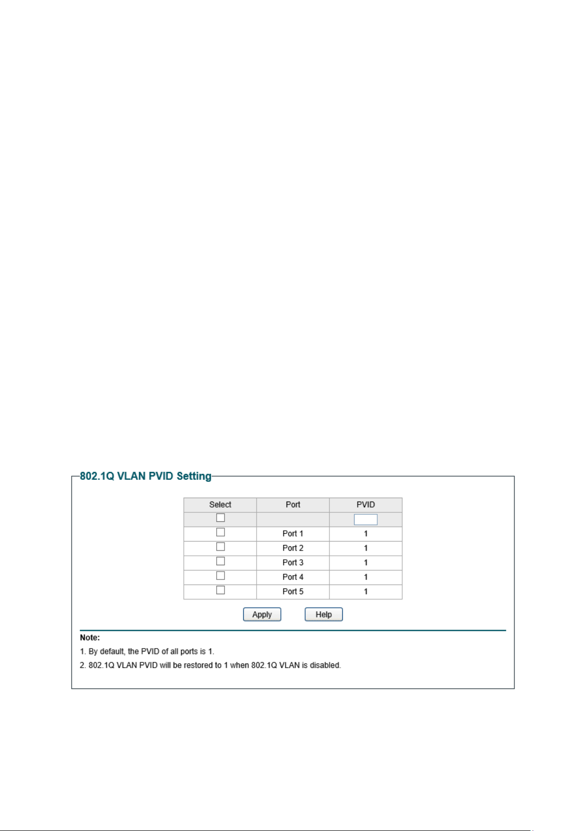
7.4 802.1Q PVID Setting
PVID (Port Vlan ID) is the default VID of the port. When the switch receives an un-VLAN-tagged
packet, it will add a VLAN tag to the packet according to the PVID of its received port and
forward the packets.
When creating VLANs, the PVID of each port, indicating the default VLAN to which the port
belongs, is an important parameter with the following two purposes:
(1) When the switch receives an un-VLAN-tagged packet, it will add a VLAN tag to the
packet according to the PVID of its received port
(2) PVID determines the default broadcast domain of the port, i.e. when the port receives
UL packets or broadcast packets, the port will broadcast the packets in its default
VLAN.
On this page you can configure PVID of the specified port. By default, the PVID of all ports is 1.
Choose the menu VLAN→802.1Q PVID Setting to load the following page.
Figure 7-6
802.1Q VLAN PVID Setting
The following entries are displayed on this screen:
802.1Q VLAN PVID Setting
32

Select:
Select the desired port for configuration. It is multi-optional.
Port:
Displays the port number.
PVID:
Enter a PVID number for the port. When adding the tag header
to the received untagged packet, the switch will automatically
uses this PVID value as the VLAN ID of the added tag.
Note:
802.1Q VLAN should be enabled before setting PVID.
Return to CONTENTS
33

1. Port Based
When port-base QoS mode is enabled, the user can manually map the ingress packets of the
port to four different priority queues. After that, the switch will preferentially send packets in
the queue with higher priority, and only when the queue with higher priority is empty, packets in
the queue with lower priority are sent.
2. 802.1P Based
Figure 8-2 802.1Q frame
As shown in the figure above, each 802.1Q Tag has a Pri field, comprising 3 bits. The 3-bit
priority field is 802.1p priority in the range of 0 to 7. The 802.1p priority value determines how
the switch maps the ingress packets to the priority queues. The mapping relationship between
eight 802.1p priority value and priority queues is shown as follows:
Figure 8-3 Map 802.1P priority
Priority 1 and 2 are assigned to the 1 (Lowest) priority queue.
Priority 0 and 3 are assigned to the 2 (Normal) priority queue.
Priority 4 and 5 are assigned to the 3 (Medium) priority queue.
Priority 6 and 7 are assigned to the 4 (Highest) priority queue.
When 802.1P QoS mode is enabled, the switch will automatically map the ingress packets to
priority queues based on the 802.1p priority and the above mapping relationship. After that, the
switch will preferentially send packets in the queue with higher priority, and only when the
queue with higher priority is empty, packets in the queue with lower priority are sent. As for the
untagged packets, the switch will forward it according to the default port-based QoS mode.
35

3. DSCP based
Figure 8-4 IP datagram
As shown in the figure above, the ToS (Type of Service) in an IP header contains 8 bits. The first
three bits indicate IP precedence in the range of 0 to 7. RFC2474 re-defines the ToS field in the
IP packet header, which is called the DS field. The first six bits (bit 0-bit 5) of the DS field
indicate DSCP priority in the range of 0 to 63. The last 2 bits (bit 6 and bit 7) are reserved. The
mapping relationship between sixty-four DSCP priority value and priority queues is shown as
follows:
Priority 0 to 15 are assigned to the 1 (Lowest) priority queue.
Priority 16 to 31 are assigned to the 2 (Normal) priority queue.
Priority 32 to 47 are assigned to the 3 (Medium) priority queue.
Priority 48 to 63 are assigned to the 4 (Highest) priority queue.
When DSCP QoS mode is enabled, the switch will automatically map the ingress packets to
priority queues based on the DSCP precedence and the above mapping relationship. After that,
packets in all the queues are sent in order based on the weight value for each queue. The
switch implements four scheduling queues, TC1, TC2, TC3 and TC4. TC1 has the lowest priority
while TC4 has the highest priority. The weight value ratio of TC1, TC2, TC3 and TC4 is 1:2:4:8.
As for the untagged packets, the switch will forward it according to the default priority mode.
The QoS module is mainly for priority configuration and traffic control, including three
submenus: QoS Basic, Bandwidth Control and Storm Control.
8.1 QoS Basic
This switch classifies the ingress packets, maps the packets to different priority queues and
then forwards the packets to implement QoS function.
This switch implements three priority modes based on port /802.1P /DSCP. The port-based QoS
mode supports four priority queues. The port priority queues are labeled as 1, 2, 3, and 4.
On this page you can configure and view QoS mode and the port-based priority setting.
Choose the menu QoS→QoS Basic to load the following page.
36
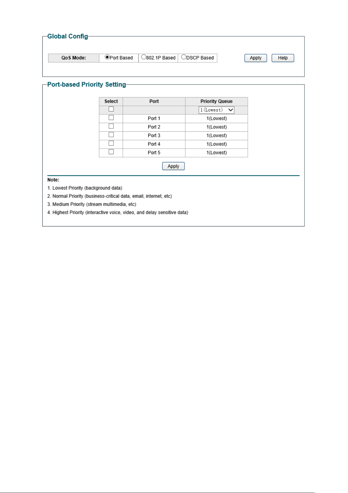
Figure 8-5 QoS Basic
The following entries are displayed on this screen:
Global Config
QoS Mode: Select the desired QoS mode.
• Port Based: The switch classifies the ing
ress packets and
maps the packets to different priority queues based on
which port the packets come from.
• 802.1p Based:
The switch classifies the ingress packets
and maps the packets to different priority queues based
on the 802.1p priority field in the 802.1Q tag.
• DSCP Based:
The switch classifies the ingress packets
and maps the packets to different priority queues based
on the DSCP priority field in the IP ToS field.
Port-based Priority Setting
Port: Select the desired port to configure its priority queue
. It is
multi-optional.
Priority Queue: Specify the priority queue the packets from the port are
mapped to. The priorities are labeled as 1~4
and among them
the bigger the value, the higher the priority.
37

8.2 Bandwidth Control
Bandwidth control functions to control the ingress/egress traffic rate on each port via
configuring the available bandwidth of each port. In this way, the network bandwidth can be
reasonably distributed and utilized.
On this page you can configure and view the bandwidth control function information.
Choose the menu QoS→Bandwidth Control to load the following page.
Figure 8-6 Bandwidth Control Setting
The following entries are displayed on this screen:
Bandwidth Control Setting
Port:
Select the desired port for bandwidth c
ontrol configuration. It
is multi-optional.
Ingress Rate(Kbps):
Here you can configure the port ingress rate limit.
If the rate for
receiving packets on the port exceeds the set rate, the packets
will be discarded.
Egress Rate(Kbps):
Here you can configure the port egress rate limit. If the rate for
sending packets on the port exceeds the set rate, the packets
will be discarded.
Note:
1. A port cannot enable both Storm Control and Ingress Rate Control at the same time.
2. When egress bandwidth control feature is enabled for one or more ports, you are
suggested to disable the flow control on each port to ensure the switch works normally.
8.3 Storm Control
Storm control function allows the switch to filter broadcast, multicast and UL frame in the
network. If the transmission rate of the chosen packets exceeds the set bandwidth, the
packets will be automatically discarded to avoid network broadcast storm.
38
On this page you can configure and view the storm control function information.
Choose the menu QoS→Storm Control to load the following page.
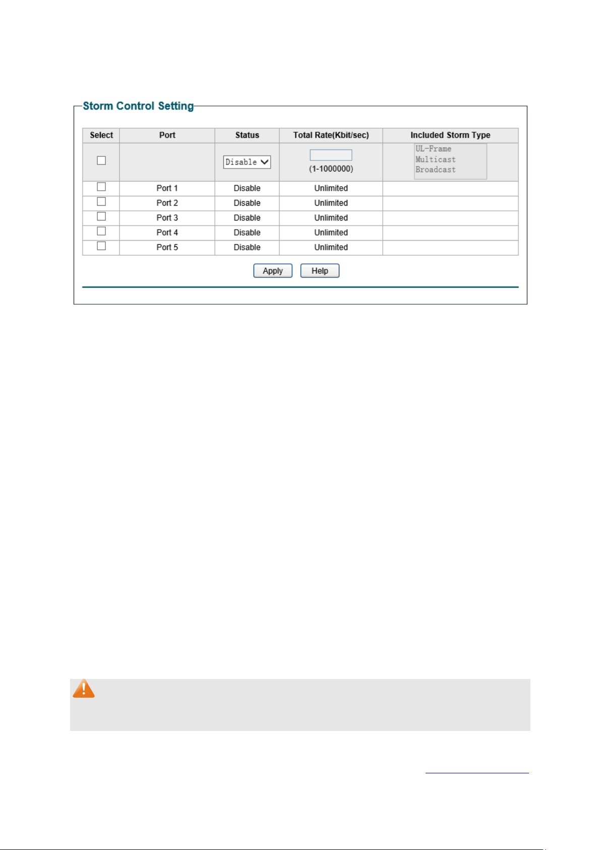
Figure 8-7 Storm Control Setting
The following entries are displayed on this screen:
Storm Control Setting
Port:
Select the desired port for storm c
ontrol configuration. It is
multi-optional.
Status:
Allows you to enable or disable the storm control function.
Total
Rate(Kbit/sec):
Select the rate
for receiving packets on the port. The packet
traffic exceeding the rate will be discarded. It ranges from 0 to
1000000, and must be integral multiple of 64.
Included Storm
Type:
Select to filter broadcast/multicast/UL frame in the network, if
the transmission rate of the chosen packets exceeds the set
rate
, the packets will be automatically discarded to avoid
network broadcast storm. It is multi-optional.
• UL-Frame: If UL-Frame packets traffic exceeds the rate on
the port, they will be discarded.
• Multicast: If multicast packets traffic exceeds the rate on
the port, they will be discarded.
• Broadcast: If broadcast packets traffic exceeds the rate
on the port, they will be discarded.
Note:
If you enable storm control feature for the ingress rate control-enabled port, the ingress rate
control feature will be disabled for this port.
Return to CONTENTS
39

Chapter 9 PoE
Note:
Only TL-SG1016PE supports configuring PoE function.
PoE (Power over Ethernet) technology describes a system to transmit electrical power along
with data to remote devices over standard twisted-pair cable in an Ethernet network. It is
especially useful for supplying power to IP telephones, wireless LAN access points, cameras
and so on.
Composition
A PoE system usually consists of PSE and PD.
PSE: Power sourcing equipment (PSE) is a device such as a switch that provides power on the
Ethernet cable to the linked device.
PD: A powered device (PD) is a device accepting power from the PSE and thus consumes
energy. PDs fall into two types, standard PDs and nonstandard PDs. Standard PDs refer to the
powered devices that comply with IEEE 802.3af and IEEE 802.3at. Examples include wireless
LAN access points, IP Phones, IP cameras, network hubs, embedded computers etc.
Advantage
Cheap cabling: The remote device such as cameras can be powered by PSE in no
need of prolonging its power cord additionally and Ethernet cable is much cheaper
than AC wire or power cord.
Easy to connect: PoE uses only one Ethernet cable with no need of external power
supply.
Reliable: A powered device can be either powered by PSE using Ethernet cable or
powered through the provided power adapter. It is very convenient to provide a
backup power supply for the PDs.
Flexibility: In compliance with IEEE 802.3af and IEEE 802.3at, global organizations can
deploy PoE everywhere without concern for any local variance in AC power standards,
outlets, plugs, or reliability.
Wide use: It can be applied to wireless LAN access points, IP Phones, IP cameras,
network hubs, embedded computers etc.
TL-SG1016PE is a Power Sourcing Equipment (PSE). Ports 1-8 on the switch support Power
over Ethernet (PoE) function, which can automatically detect and supply power for those
powered devices (PDs) complying with IEEE 802.3af and IEEE 802.3at. The maximum power
TL-SG1016PE can supply is 110W and the maximum power each PoE port can supply is 30W.
40
9.1 PoE Config
On this page, you can configure the parameters to implement PoE function.
Choose the menu PoE→PoE Config to load the following page.
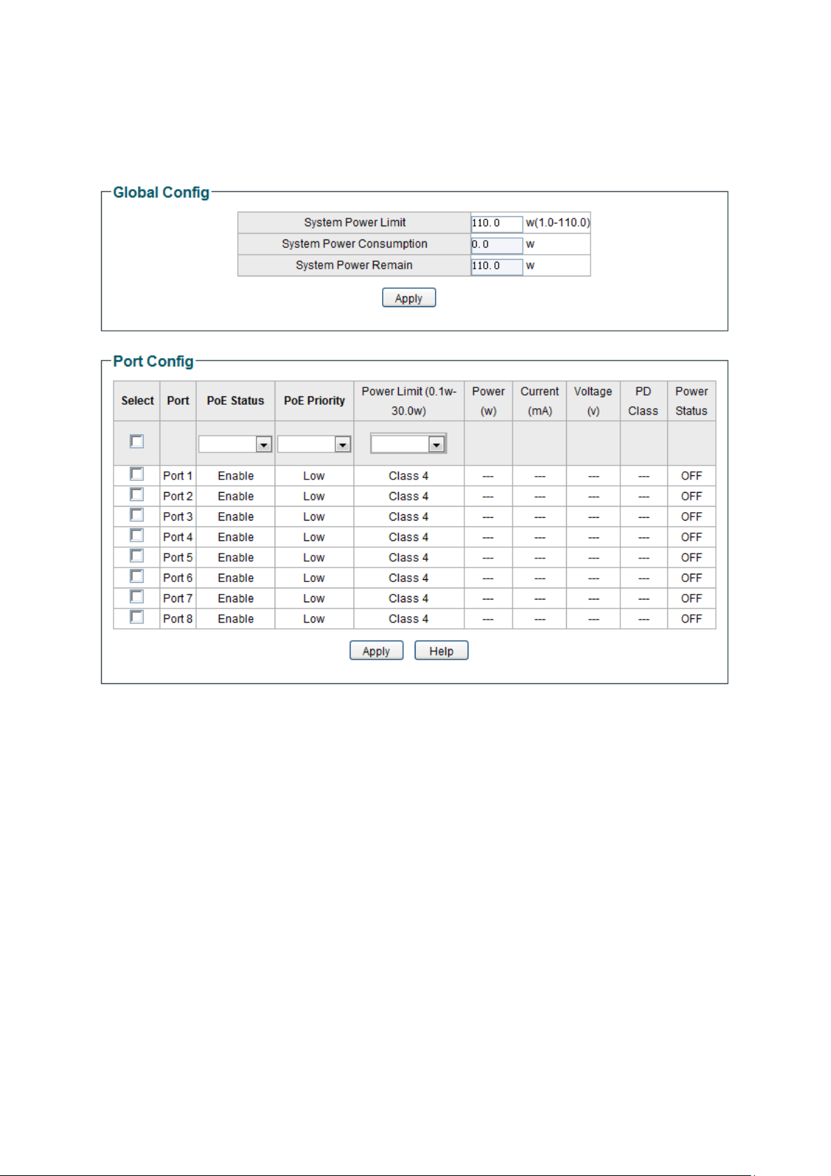
Figure 9-1 PoE Config
The following entries are displayed on this screen:
Global Config
System Power Limit:
Specify the max power the PoE switch can supply. It ranges
from
1W to 110W.
System Power
Consumption:
Displays the PoE switch's real time system power consumption.
System Power
Remain:
Displays the PoE switch's real time remaining system power.
Port Config
Port:
Select the desired port for PoE configuration. I
t is
multi-optional.
41

PoE Status:
Select to disable/enable the PoE feature for the corresponding
port. If set enable, the corresponding port can supply power to
the linked PD (Powered Device).
PoE Priority:
The priority levels include High, Middle and Low in descending
order. When the supply power exceeds the system power limit,
the port with lower priority will stop supplying power; If these
ports have the same priority levels, the port with larger port
number will stop supplying power first.
Power Limit
(0.1w-30w):
Defines the max power the corresponding port can supply.
Class1 represents 4W, Class2 represents 7W, Class3
represents 15.4W and Class4 represents 30W.
Power (W):
Displays the port's real time power supply.
Current (mA):
Displays the port's real time current.
Voltage (V):
Displays the port's real time voltage.
PD Class:
Displays the class the linked PD (Powered Device) belongs to.
Power Status:
Displays the port's real time power status.
Return to CONTENTS
42

Appendix A: Specifications
Standards
IEEE802.3 Ethernet Media Access Control (MAC) Protocol
IEEE802.3i 10Base-T Ethernet
IEEE802.3u 100Base-TX Fast Ethernet
IEEE802.3ab 1000Base-T Gigabit Ethernet
IEEE802.3x Flow Control
IEEE802.3af (only TL –SG108PE/TL-SG1016PE support)
IEEE802.3at (only TL-SG1016PE supports)
IEEE802.1p QoS
IEEE802.1q VLAN
Transmission Rate
Ethernet: 10Mbps HD, 20Mbps FD
Fast Ethernet: 100Mbps HD, 200Mbps FD
Gigabit Ethernet: 2000Mbps FD
Transmission Medium
10Base-T: UTP/STP of Cat. 3 or above
100Base-TX: UTP/STP of Cat. 5 or above
1000Base-T: 4-pair UTP (≤100m) of Cat. 5, Cat. 5e, Cat.6
or above
LED
For TL-SG105E/ TL-SG108E:
Power, 10/100Mbps,1000Mbps
For TL-SG108PE:
Power, PoE Max , Link/Act(Port 1- 8), PoE Status(Port 1- 4)
For TL-SG1016DE/ TL-SG1024DE:
Power, 1000Mbps, Link/Act
For TL-SG1016PE:
PWR, PoE Max, Speed(Port1- 16), PoE Status(Port 1-
8),
FAN
Transmission Method
Store and Forward
Packets Forwarding Rate
10BASE-T:14881pps/port
100BASE-TX:148810pps/port
1000Base-T
:
1488095pps/port
43

Operating
Environment
Operating Temperature: 0℃ to 40℃
Storage Temperature: -40℃ to 70℃
Operating Humidity: 10% to 90% RH Non-condensing
For TL-SG105E/ TL-SG108E/ TL-SG108PE:
Storage Humidity: 5% to 95% RH Non-condensing
For TL-SG1016DE/ TL-SG1024DE/TL-SG1016PE:
Storage Humidity: 5% to 90% RH Non-condensing
Return to CONTENTS
44