INPL3019SSNB-B
INPL3619SSNB-B
INPL3622SSNB-B
INPL4219SSNB-B
INPL4819SSNB-B
INPL4822SSNB-B
Installation Instructions
Use and Care Information
Instructions d'installation
Utilisez et d'entretien
INCA PRO PLUS

2
READ AND SAVE THESE INSTRUCTIONS BEFORE YOU START
INSTALLING THIS RANGEHOOD
WARNING: - TO REDUCE THE RISK OF A RANGE TOP GREASE FIRE:
a) Never leave surface units unattended at high settings. Boilovers cause smoking and greasy
spillovers that may ignite. Heat oils slowly on low or medium setting.
b) Always turn hood ON when cooking at high heat or when ambeing food (i.e. Crepes Suzette,
Cherries Jubilee, Peppercorn Beef Flambé).
c) Clean ventilating fans frequently. Grease should not be allowed to accumulate on fan or lter.
d) Use proper pan size. Always use cookware appropriate for the size of the surface element.
WARNING: - TO REDUCE THE RISK OF INJURY TO PERSONS IN THE EVENT OF A RANGE TOP
GREASE FIRE, OBSERVE THE FOLLOWING*:
a) SMOTHER FLAMES with a close-tting lid, cookie sheet, or metal tray, then turn o the burner. BE
CAREFUL TO PREVENT BURNS. If the ames do not go out immediately EVACUATE AND CALL THE
FIRE DEPARTMENT.
b) NEVER PICK UP A FLAMING PAN - You may be burned.
c) DO NOT USE WATER, including wet dishcloths or towels - a violent steam explosion will result.
d) Use an extinguisher ONLY if:
1. You know you have a Class ABC extinguisher, and you already know how to operate it.
2. The re is small and contained in the area where it started.
3. The re department is being called.
4. You can ght the re with your back to an exit.
* Based on "Kitchen Firesafety Tips" published by NFPA
WARNING - TO REDUCE THE RISK OF FIRE OR ELECTRIC SHOCK, do not use this fan with any
solid-state speed control device.
WARNING - TO REDUCE THE RISK OF FIRE, ELECTRIC SHOCK, OR INJURY TO PERSONS, OBSERVE
THE FOLLOWING:
a) Use this unit only in the manner intended by the manufacturer. If you have any questions,
contact the manufacturer.
b) Before servicing or cleaning unit, switch power o at service panel and lock the service discon-
necting means to prevent power from being switched on accidentally.
When the service disconnecting means cannot be locked, securely fasten a prominent warning
device, such as a tag, to the service panel.
CAUTION: For General Ventilating Use Only. Do Not Use To Exhaust Hazardous or Explosive
Materials and Vapors.
WARNING - TO REDUCE THE RISK OF FIRE, ELECTRICAL SHOCK, OR INJURY TO PERSONS, OB-
SERVE THE FOLLOWING:
1. Installation Work And Electrical Wiring Must Be Done By Qualied Person(s) In Accordance
With All Applicable Codes And Standards, Including Fire-Rated Construction.
2. Sucient air is needed for proper combustion and exhausting of gases through the ue
(chimney) of fuel burning equipment to prevent backdrafting. Follow the heating equipment
manufacturer's guideline and safety standards such as those published by the National
Fire Protection Association (NFPA), and the American Society for Heating, Refrigeration
and Air Conditioning Engineers (ASHRAE), and the local code authorities.

3
ALL WALL AND FLOOR OPENINGS WHERE THE RANGEHOOD IS INSTALLED
MUST BE SEALED.
This rangehood requires at least 24" of clearance between the bottom of the rangehood and the cooking
surface or countertop. This hood has been approved by UL at this distance from the cooktop.
This minimum clearance may be higher depending on local building codes. For gas cooktops and combination
ranges, a minimum of 30" is recommended and may be required.
Overhead cabinets on both sides of this unit must be a minimum of 18" above the cooking surface or
countertop. Consult the cooktop or range installation instructions given by the manufacturer before
making any cutouts.
MOBILE HOME INSTALLATION The installation of this rangehood must conform to the Manufactured Home
Construction and Safety Standards, Title 24 CFR, Part 3280 (formerly Federal Standard for Mobile Home
Construction and Safety, Title 24, HUD, Part 280). See Electrical Requirements.
• Venting system MUST terminate outside the home.
• DO NOT terminate the ductwork in an attic or other enclosed space.
• DO NOT use 4" laundry-type wall caps.
• Flexible-type ductwork is not recommended.
• DO NOT obstruct the ow of combustion and ventilation air.
• Failure to follow venting requirements may result in a re.
WARNING
!
VENTING REQUIREMENTS
Determine which venting method is best for your application. Ductwork can extend either through the wall
or the roof.
The length of the ductwork and the number of elbows should be kept to a minimum to provide ecient
performance. The size of the ductwork should be uniform. Do not install two elbows together. Use duct tape
to seal all joints in the ductwork system. Use caulking to seal exterior wall or oor opening around the cap.
Flexible ductwork is not recommended. Flexible ductwork creates back pressure and air turbulence that
greatly reduces performance.
Make sure there is proper clearance within the wall or oor for exhaust duct before making cutouts. Do not
cut a joist or stud unless absolutely necessary. If a joist or stud must be cut, then a supporting frame must
be constructed.
WARNING - To Reduce The Risk Of Fire, Use Only Metal Ductwork.
CAUTION - To reduce risk of re and to properly exhaust air, be sure to duct air outside – Do not vent
exhaust air into spaces within walls or ceilings or into attics, crawl spaces, or garages.
3. When cutting or drilling into wall or ceiling, do not damage electrical wiring and other
hidden utilities.
4. Ducted fans must always be vented to the outdoors.
4
ELECTRICAL REQUIREMENTS
A 120 volt, 60 Hz AC-only electrical supply is required on a separate 15 amp fused circuit. A time-delay
fuse or circuit breaker is recommended. The fuse must be sized per local codes in accordance with the
electrical rating of this unit as specied on the serial/rating plate located inside the unit near the eld wiring
compartment.
ELECTRICAL INSTALLATION WITH WIRING BOX
THIS UNIT MUST BE CONNECTED WITH COPPER WIRE ONLY. Wire sizes must conform to the requirements
of the National Electrical Code, ANSI/NFPA 70 - latest edition, and all local codes and ordinances. Wire size
and connections must conform with the rating of the appliance. Copies of the standard listed above may
be obtained from:
National Fire Protection Association
Batterymarch Park
Quincy, Massachusetts 02269
This appliance should be connected directly to the fused disconnect (or circuit breaker) through
exible, armored or nonmetallic sheathed copper cable. Allow some slack in the cable so the ap-
pliance can be moved if servicing is ever necessary. A UL Listed, 1/2" conduit connector must be
provided at each end of the power supply cable (at the appliance and at the junction box).
When making the electrical connection, cut a 1 1/4" hole in the wall. A hole cut through wood must
be sanded until smooth. A hole through metal must have a grommet.
• Electrical ground is required on this rangehood.
• If cold water pipe is interrupted by plastic, nonmetallic gaskets or other materials, DO NOT
use for grounding.
• DO NOT ground to a gas pipe.
• DO NOT have a fuse in the neutral or grounding circuit. A fuse in the neutral or grounding
circuit could result in electrical shock.
• Check with a qualied electrician if you are in doubt as to whether the rangehood is
properly grounded.
• Failure to follow electrical requirements may result in a re.
WARNING
!
State of California Proposition 65 Warning (US only)
WARNING
This product contains chemicals known to the State of California to cause cancer and birth
defects or other reproductive harm.
For more information go to www.P65Warnings.ca.gov
5
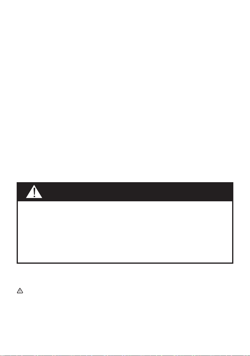
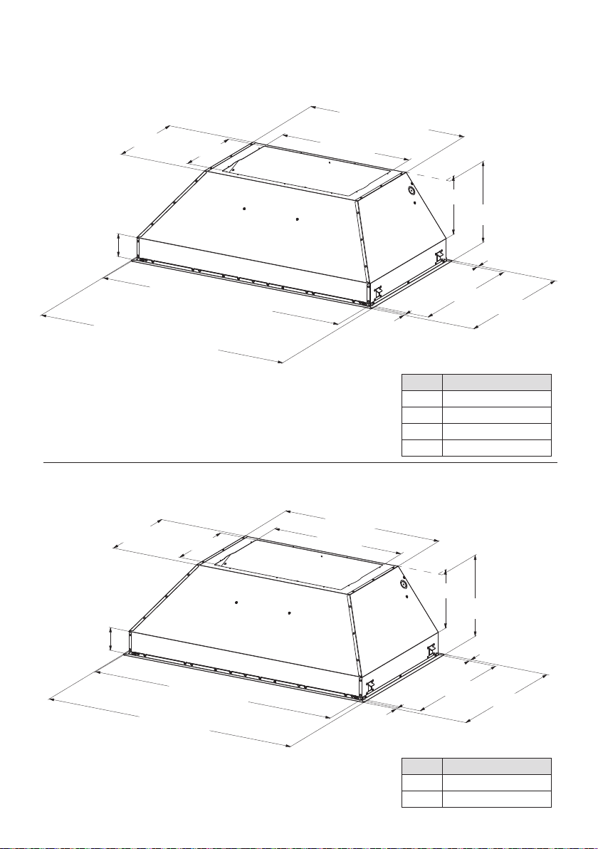
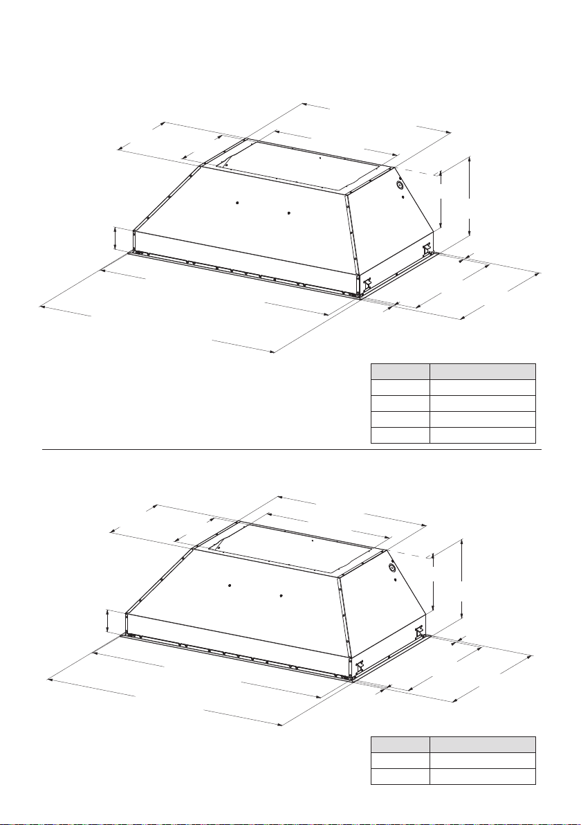
RANGEHOOD DIMENSIONS
12-5/16"
10-13/16"
18-11/16"
21-1/4" (A1) - 22-1/2" (A2)
28-9/16" (A3) - 34-9/16" (A4)
7-15/16"
1/2"
3-1/8"
11"
28-1/2" (A1) - 34-1/2" (A2)
40-9/16" (A3) - 46-9/16" (A4)
29-1/2" (A1) - 35-1/2" (A2)
41-9/16" (A3) - 47-9/16" (A4)
1/2"
20-11/16"
19-11/16"
15-5/16"
10-13/16"
18-11/16"
22-1/2" (A1) - 34-9/16" (A2)
7-15/16"
1/2"
3-1/8"
11"
34-1/2" (A1) - 46-9/16" (A2)
35-1/2" (A1) - 47-9/16" (A2)
1/2"
23-11/16"
22-11/16"
Index Model #
A1 INPL3019SSNB-B
A2 INPL3619SSNB-B
A3 INPL4219SSNB-B
A4 INPL4819SSNB-B
Index Model #
A1 INPL3622SSNB-B
A2 INPL4822SSNB-B
6
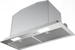
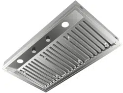
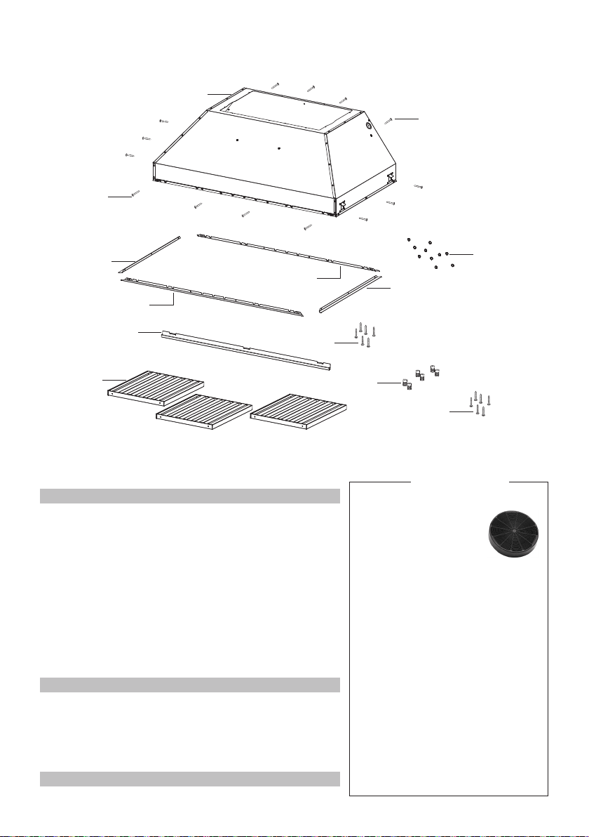
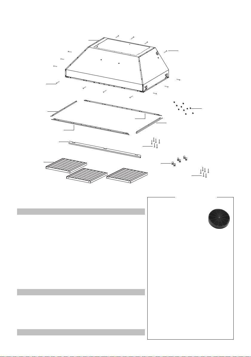
MAIN PARTS
Components
Ref. Qty. Product Components
1 1 Hood Body, complete with:
Controls, Light, Filters, Blower.
4 2 Front / back trim
5 2 Left/right trim
6 2 Greaselters(30")
6 3 Greaselters(36"-42")
6 4 Greaselters(48")
7 4 Filterknobs(30")
7 6 Filterknobs(36"-42")
7 8 Filterknobs(48")
8 1 Greaserail
10 10 Stopper
Ref. Qty. Installation Components
9c 14 Installscrews(1/8"x1/4")
9d 6 Installscrews(1/8"x5/16")
9e 4 Greaseltersscrews(3/16"x5/16"-30")
9e 6 Greaseltersscrews(5/32"x5/16"-36"-42")
9e 8 Greaseltersscrews(5/32"x5/16"-48")
Qty. Documentation
1 Instruction Manual
Activated Charcoal
Filter sku #; FILTER1
Activated Charcoal
Filter sku #; FILTER1LL
Internal 300 cfm Blower sku #; IB300
Internal 600 cfm PRO Blower sku #;
IB600
Internal 1,200 cfm PRO Blower sku #;
IB1200
Remote Blower 900 cfm
sku #; RB900
Remote Blower 1,200 cfm
sku #; RB1200
In-Line Blower Connection Kit sku #;
INLBKIT
1
9c
9c
5
8
7
5
4
4
6
9d
10
9e
Available
Accessories
7
Version 07/11 - Page 6
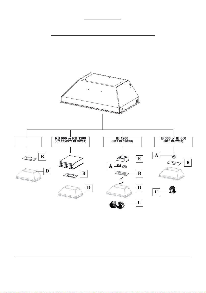
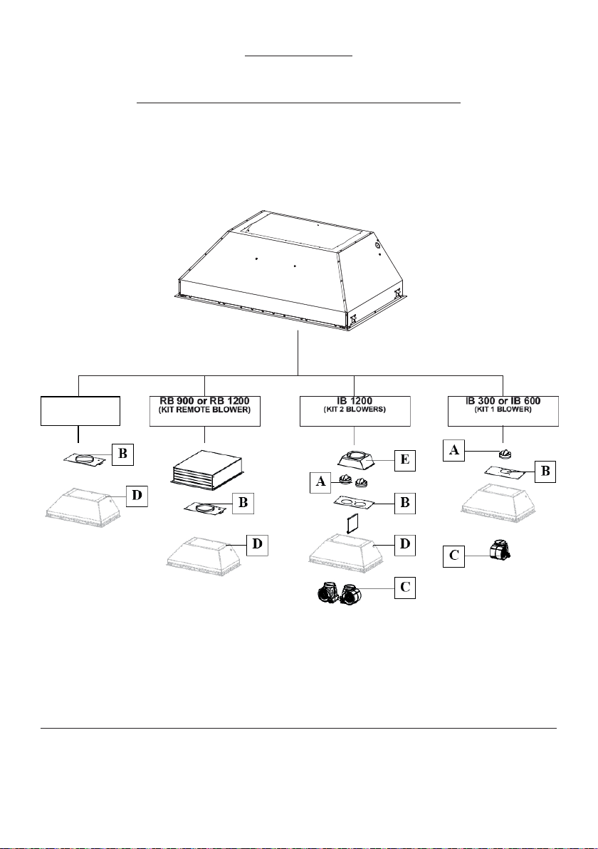
INSTALLATION
COMBINATIONS HOOD AND MOTOR KITS
CHOOSE A BLOWER FOR YOUR HOOD
After choosing the hood width and depth for your cooking
needs, next choose the type of blower appropriate for
your cooking.
NOTE: no other blower is
compatible with this hood, except for the
kits below.
# IB300 - Internal Blower Kit 300 cfm
# IB600 - Internal Blower Kit 600 cfm
# IB1200 - Internal Blower Kit 1200 cfm
# RB900 - Remote Blower Kit 900 cfm
# RB1200 - Remote Blower Kit 1200 cfm
# INLBKIT - In Line Blower Kit
(supply own in-line blower)
OPTIONAL ACCESSORIES AVAILABLE
• *Charcoal Filter
* it is highly recommended that professional style cooking always be
vented to the outside; for recirculating installations only, some ductwork is
required to exhaust the unit out of the cabinet. Replace as needed with the
same model
part # FILTER1
NOTE: The charcoal filter kit for use with the 300 / 600
cfm internal blower kit ONLY
CAUTION - To reduce risk of fire and electric shock, install this rangehood only with: Remote blower manufacturer by Faber
models RB900 and RB1200 or Integral blower manufactured by Faber models IB300 or IB600 or IB1200 or with INLBKIT and
generic in-line blower rated max 4.2 A suitable for use with solid state variable speed control
INLBKIT
CAUTION - To reduce the risk of re and electric shock, install this rangehood only with Remote blower
manufactured by Faber models RB900 and RB1200, or Internal blower manufactured by Faber models IB300
or IB600 or IB1200 with the INLBKIT accessory kit purchased separately. When using a generic In-Line Blower
or Remote Blower it must be rated maximum 4.2 A suitable for use with solid state variable speed control and
also used with the INBKLIT accessory kit purchased separately.
For the 30" Inca it is recommended that blowers are kept at MAX. CFM of 600.
INSTALLATION
COMBINATIONS HOOD AND MOTOR KITS
8
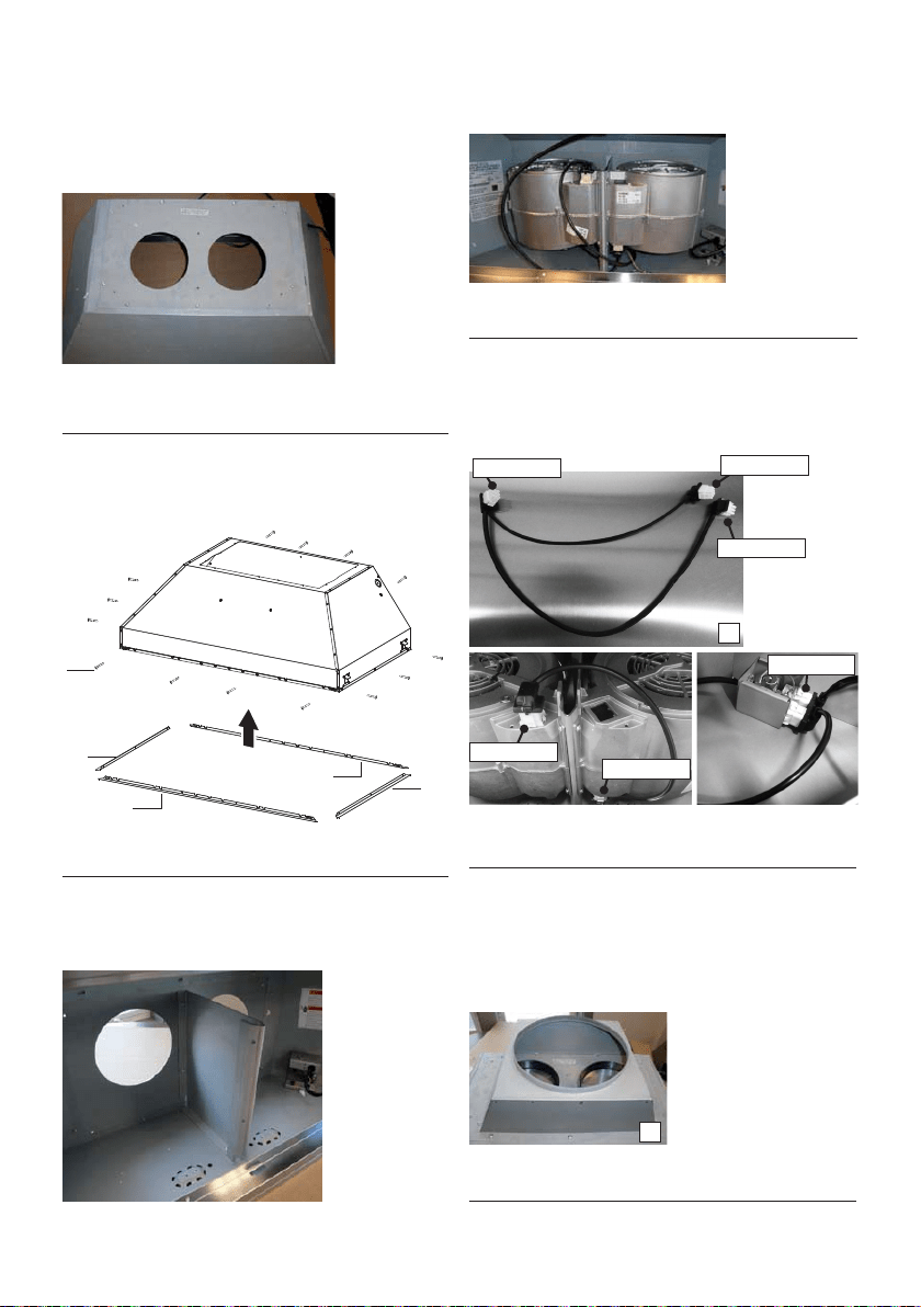
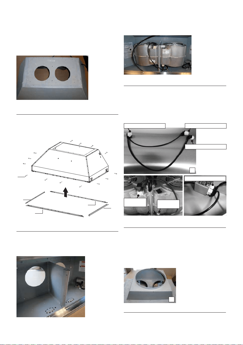
1. Install the Plate B (Figure 2) which came with
the internal blower kit, on top of the rangehood
with the hole closer to the back of the hood. Use 9
screws supplied with the blower kit.
5
5
4
4
9c
Version 07/11 - Page 8
INSTALLATION WITH IB300 / IB600 INTERNAL BLOWER (300
, 600 cfm)
1. Install the Plate B (FIGURE 8) which came with the internal
blower kit, on top of the rangehood with the hole closer to the back
of the hood. Use 9 screws supplied with the blower kit
6. (see FIGURE 13) Remove the cover from the field wiring
compartment with a phillips screwdriver. Feed the Power Supply
Cable through the electrical knockout. Connect the Power Supply
Cable to the rangehood cable. Attach the White lead of the power
supply to the White lead of the rangehood with a twist-on type wire
connector. Attach the Black lead of the power supply to the Black
lead of the rangehood with a twist-on type wire connector. Attach
the Power Supply Cable grounding lead to the green screw provided.
Replace the cover.
7. Connect the ductwork to the damper and seal all connections with
duct tape. Install the grease filters and grease rail. (see page 11 for
instructions)
8. Turn the power supply on. Turn on the blower and light. If the
rangehood does not operate, check that the circuit breaker is not
tripped or the house fuse blown. If the unit still does not operate,
disconnect the power supply and check that the wiring connections
have been made properly.
9. CONTINUE TO PAGE 11
FIGURE 8
2. Remove the white plastic covering and install the 4 side trim
pieces to the outside of the hood using (16) part 9b screws, see
the side rail installation in (FIGURE 9).
FIGURE 9
5. Attach the hood to the cabinet using (12) 9c. screws to the
cabinet. FIGURE 12
FIGURE 12
FIGURE 10
3. Install the motor kit into the hood using the 2 screws supplied
with the motor kit into the back of the hood. (FIGURE 10)
4. Connect the wire that comes with the motor kit from the side
of the motor to the connection on the inside of the light panel in
the hood. The 9 hole end of the wire is installed in the motor, the
6 hole end is connected to the light panel (FIGURE 11)
FIGURE 11
FIGURE 13
B
FOR ALL INSTALLATIONS REMOVE ALL WHITE PLASTIC PROTECTIVE COVERING FROM
HOOD, SIDE RAILS, TRIM, GREASE RAILS AND GREASE FILTERS.
2. Remove the white plastic covering and install
the 4 side trim pieces (4-5) to the outside of the
hood using (14) part 9c screws, see the side trim
installation in (Figure 3).
INSTALLATION WITH IB300 / IB600 INTERNAL BLOWER
(300, 600 cfm)
FIGURE 2
FIGURE 3
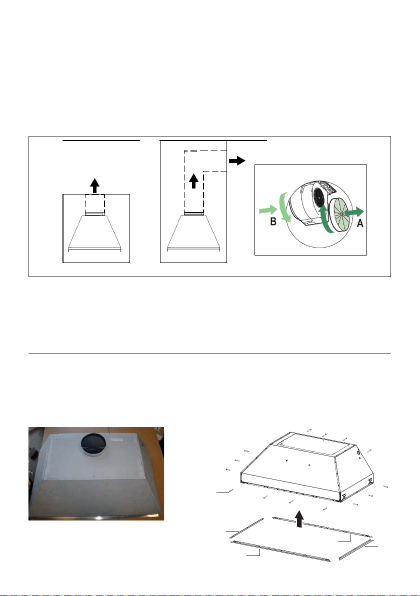
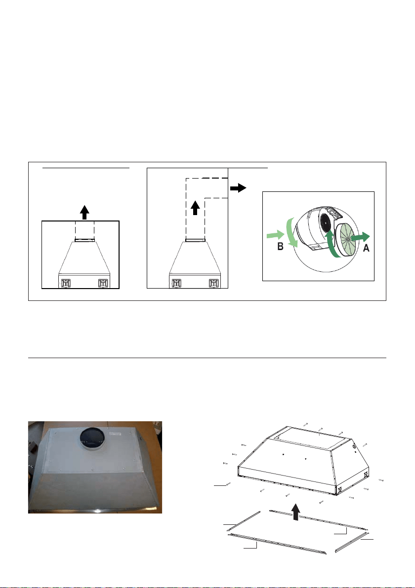
RECIRCULATING INSTALLATIONS
IT IS HIGHLY RECOMMENDED THAT PROFESSIONAL STYLE COOKING ALWAYS BE VENTED
TO THE OUTSIDE. For recirculating installations (Figure 1), Charcoal Filters are necessary. Remove
all grease lters and set aside. Attach one charcoal lter to each end of the blower. Each charcoal lter
attaches to the grid on the side of the blower. Rotate the lter clockwise to install and counterclockwise
to remove (Figure 1A). Replace all grease lters. Recirculating installations also require some duct work
to divert the air out of the top or face or side of the cabinet or custom hood or out of the side / face of
the sot and back into the kitchen. Install at least 15" of vertical run of metal duct (Figure 1) at the air
outlet. Run the duct vertically and secure it at the relevant opening previously cut out at the top or side
of the cabinet or sot. A metal duct cover grille is also recommended. The duct work must not terminate
inside the cabinet or custom hood.
Version 07/11 - Page 7
PLAN YOUR DUCTWORK
To ensure that the blower performs to its highest
possible capacity, ductwork should be as short
and straight as possilbe.
The ductrun should not exceed 35 equivalent
feet if ducted using the required minimum of 6"
round duct. For 10" round ducting with the 1200
cfm internal motor or 900 / 1200 remote blower,
use 55 equivalent feet. Calculate the length of
the ductwork by adding the equivalent feet in
FIGURE 5 for each piece of duct in the system
An example is given in FIGURE 6.
For best results, use no more than three 90°
elbows. Make sure that there is a minimum of
24" of straight duct between elbows if more
than one is used. Do not install two elbows
together. If you must elbow right away, do it
as far away from the hood's exhaust opening
as possible.
9 Feet Straight Duct
2 - 90˚ Elbows
Wall Cap
Total System
9.0 feet
10.0 feet
0.0 feet
19.0 feet
FIGURE 6
3.0 feet
5.0 feet
12.0 feet
0.0 feet
45˚ Elbow
90˚ Elbow
90˚ Flat Elbow
Wall Cap
FIGURE 5
FIGURE 4
RECIRCULATING INSTALLATIONS
IT IS HIGHLY RECOMMENDED THAT PROFESSIONAL STYLE COOKING ALWAYS BE VENTED TO THE OUTSIDE. For recirculating
installations (FIGURE 4), Charcoal Filters are necessary. Remove all grease filters and set aside. Attach one charcoal filter to each end
of the blower. Each charcoal filter attaches to the grid on the side of the blower. Rotate the filter clockwise to install and counterclockwise
to remove (FIGURE 4A). Replace all grease filters. Recirculating installations also require some duct work to divert the air out of the top or
face or side of the cabinet or custom hood or out of the side / face of the soffit and back into the kitchen. Install at least 15" of vertical run of
metal duct (FIGURE 4) at the air outlet. Run the duct vertically and secure it at the relevant opening previously cut out at the top or side of
the cabinet or soffit. A metal duct cover grille is also recommended. The duct work must not terminate inside the cabinet or custom hood.
cabinet
or
custom
hood
ceiling
duct
work
duct
work
ceiling
inca pro plus
cabinet
or
custom
hood
MAKE YOUR CUT-OUTS
1. Disconnect and move freestanding range from cabinet opening to provide easier access
to upper cabinet or custom hood. Put a thick, protective covering over cooktop, set-in range
or countertop to protect from damage or dirt.
2. Determine and make all necessary cuts in the wall and/or ceiling for the ductwork. Install
the ductwork before the rangehood.
3. Determine the proper location for the Power Supply Cable. Use a 1
1/4"
Drill Bit to make
this hole. Install the cable. Use caulking to seal around the hole. DO NOT turn on the
power until installation is complete.
4. Choose the knock out hole to remove for installing the power cable. Use a screwdriver
to snap off the knock out covering. (FIGURE 7 shows inside the wiring box and outside)
FIGURE 4A
inca pro plus
FIGURE 7
FOR ALL INSTALLATIONS
REMOVE ALL WHITE PLASTIC PROTECTIVE COVERING FROM HOOD, SIDE RAILS,
TRIM, GREASE RAILS AND GREASE FILTERS
FIGURE 1
FIGURE 1A
9
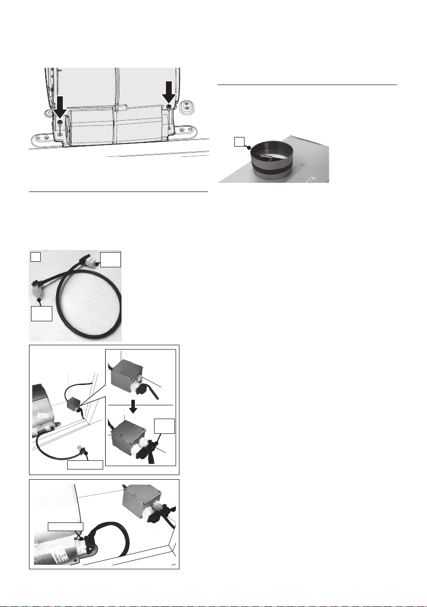
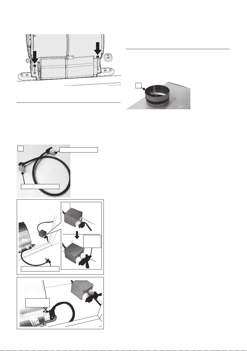
3. Install the motor kit into the back of the hood
using the 2 screws supplied with the motor kit
(Figure 4).
5. Connect the ductwork to the damper and seal all
connections with duct tape.
4. Connect the wire cable D (which is located
inside of Kit Internal 300 cfm Blower sku #; IB300
or Internal 600 cfm PRO Blower sku #; IB600).
Connect the 6 hole end to the wire box and connect
the 9 hole end to the motor (Figure 5).
FIGURE 4
6 hole
end
9 hole
end
D
FIGURE 5
9 hole end
FIGURE 6
A
6. Before installing the hood, put the damper A
(which is located inside of Kit Internal 300 cfm
Blower sku #; IB300 or Internal 600 cfm PRO
Blower sku #; IB600) (Figure 6).
9 hole end
6 hole
end
10
INSTALLATION WITH IB1200 INTERNAL
BLOWER (1200 cfm)
1. Install the Duct Plate B (Figure 7) which came
with the internal blower kit, on top of the rangehood
with the holes located closer to the front. Use 9
screws supplied with the blower kit.
2. Remove the white plastic covering and Install
the 4 side trim pieces (4-5) to the outside of the
hood using (14) part 9c screws, see the side trim
installation in (Figure 8).
3. Attach the blower bracket divider inside the
hood with the 2 screws into the top of the hood
and 2 screws into the back, all supplied with the
blower kit (Figure 9).
5
5
4
4
9c
Version 07/11 - Page 9
INSTALLATION WITH IB1200 INTERNAL BLOWER (1200 cfm)
1. Install the Plate B (FIGURE 14) which came with the internal
blower kit, on top of the rangehood with the holes located closer to
the front. Use 9 screws supplied with the blower kit
2. Remove the white plastic covering and Install the 4 side trim
pieces to the outside of the hood using (16) part 9b screws, see
the side rail installation in (FIGURE 15).
3. Attach the blower bracket divider inside the hood, with the 2
screws into the top of the hood and 2 screws into the back, all
supplied with the blower kit (FIGURE 16)
FIGURE 16
FIGURE 17
4. Install the 2 motor kits into the sides of the blower bracket using
the 4 screws supplied with the motor kit. (FIGURE 17)
5. Connect the wire (FIGURE 18) that comes with the motor kit
from the side of the two motors to the connection on the inside
of the light panel in the hood. The two - 9 hole ends of the wire
are installed in the two motors, the 6 hole end is connected to
the light panel (FIGURE 11 on the previous page)
FIGURE 15
FIGURE 18
FIGURE 19
6. Install the 2 dampers on top of the hood. If you want one 10"
round duct to come out of the top of the hood, use the transition
piece (FIGURE 19) that comes with the motor kit and install with
four screws. If you want to use 2 seperate 6" round ducts, do not
use the transition.
7. Attach the hood to the cabinet using (12) 9c. screws to the
cabinet. FIGURE 20
8. Follow steps 6 - 9 on the previous page to connect ducting,
wiring, and test the electrical connection.
FIGURE 14
FIGURE 20
B
4. Install the 2 motor kits into the sides of the
blower bracket using the 4 screws supplied with
the motor kit (Figure 10).
7. Follow step 4 on page 13 to connect ducting,
wiring, and test the electrical connection.
FIGURE 7
FIGURE 8
FIGURE 9
FIGURE 10
5. Connect the wire cable D (which is located
inside of Kit Internal 1,200 cfm PRO Blower sku
#; IB1200). Connect the 6 hole end (A) to the wire
box and connect the 9 hole end (B-C) to the two
motors (Figure 11).
FIGURE 11
A) 6 hole end
C) 9 hole end
B) 9 hole end
A) 6 hole end
C) 9 hole end
B) 9 hole end
D
6. Install the 2 dampers (A) on top of the hood
(which is located inside of Kit Internal 1,200 cfm
PRO Blower sku #; IB1200). Alternatively, install
the 10" duct transition (E) (which is located inside
of Kit Internal 1,200 cfm PRO Blower sku #;
IB1200) and install with four screws (Figure 12).
Version 07/11 - Page 9
INSTALLATION WITH IB1200 INTERNAL BLOWER (1200 cfm)
1. Install the Plate B (FIGURE 14) which came with the internal
blower kit, on top of the rangehood with the holes located closer to
the front. Use 9 screws supplied with the blower kit
2. Remove the white plastic covering and Install the 4 side trim
pieces to the outside of the hood using (16) part 9b screws, see
the side rail installation in (FIGURE 15).
3. Attach the blower bracket divider inside the hood, with the 2
screws into the top of the hood and 2 screws into the back, all
supplied with the blower kit (FIGURE 16)
FIGURE 16
FIGURE 17
4. Install the 2 motor kits into the sides of the blower bracket using
the 4 screws supplied with the motor kit. (FIGURE 17)
5. Connect the wire (FIGURE 18) that comes with the motor kit
from the side of the two motors to the connection on the inside
of the light panel in the hood. The two - 9 hole ends of the wire
are installed in the two motors, the 6 hole end is connected to
the light panel (FIGURE 11 on the previous page)
FIGURE 15
FIGURE 18
FIGURE 19
6. Install the 2 dampers on top of the hood. If you want one 10"
round duct to come out of the top of the hood, use the transition
piece (FIGURE 19) that comes with the motor kit and install with
four screws. If you want to use 2 seperate 6" round ducts, do not
use the transition.
7. Attach the hood to the cabinet using (12) 9c. screws to the
cabinet. FIGURE 20
8. Follow steps 6 - 9 on the previous page to connect ducting,
wiring, and test the electrical connection.
FIGURE 14
FIGURE 20
B
FIGURE 12
E
11
5
5
4
4
9c
INSTALLATION WITH REMOTE BLOWER (RB900 / RB1200) OR IN-LINE BLOWER (INLBKIT)
NOTE: FOLLOW THE INSTRUCTIONS INCLUDED WITH THE REMOTE BLOWER TO
INSTALL THE BLOWER ON THE OUTSIDE OF YOUR HOME.
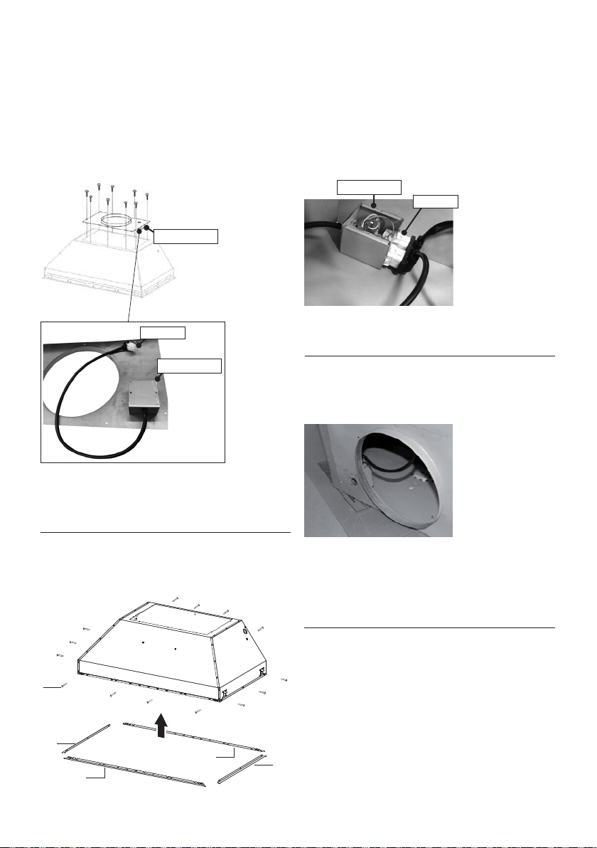
1. Install the Plate B with the second wiring box
(Figure 13) which came with the remote blower kit,
on top of the rangehood. Use 9 screws supplied with
the blower kit. Remove the electrical knockout hole
on top of the plate.
2. Remove the white plastic covering and Install the
4 side trim pieces (4-5)
to the outside of the hood
using (14) part 9c screws, see the side rail installation
in (Figure 14).
FIGURE 14
3. Connect the wire coming out from the 2
nd
wiring box
to the 6 hole end of the 1
st
wiring box.
Connect the wire that comes out from the black box of
the electronic board to the 9 hole end of the 1
st
wiring
box (Figure 15).
Version 07/11 - Page 10
INSTALLATION WITH REMOTE BLOWER (RB900 / RB1200)
OR IN-LINE BLOWER (INLBKIT)
NOTE: FOLLOW THE INSTRUCTIONS INCLUDED WITH THE
REMOTE BLOWER TO INSTALL THE BLOWER ON THE
OUTSIDE OF YOUR HOME
.
1. Install the Plate B (FIGURE 21) which came with the remote
blower kit, on top of the rangehood. Use 9 screws supplied with
the blower kit. Remove the electrical knockout hole on top of the
plate.
2. Remove the white plastic covering and Install the 4 side trim
pieces to the outside of the hood using (16) part 9b screws, see
the side rail installation in (FIGURE 22).
FIGURE 23
FIGURE 24
4. Feed the remote blower cable thru the knockout hole in step 1
(FIGURE 24). Connect the power supply cable from the remote
blower to the wiring box on the top ducting plate of the hood. Use
step 6 on page 8 and the diagram on page 8 (FIGURE 13)
5. Attach the hood to the cabinet using (12) 9c. screws to the
cabinet. FIGURE 25
6. Follow steps 6 - 9 on page 8 to connect ducting, wiring, and
test the electrical connection. Use the wiring box connected to
the inside wall of the hood which connects to the home power
supply thru the knockout on the side of the hood.
FIGURE 21
FIGURE 22
3. Connect the wire coming out of the wiring box on the top duct
plate to the light panel 6 hole slot connector on the front inside
of the hood (FIGURE 23)
FIGURE 25
B
4.
Pass the remote blower cable through the
knockout
hole in step 1
(Figure 13,16). Connect this
cable from the remote blower to the 2
nd
wiring box
placed on the lower surface of plate B.
5. Follow step 4 on page 13 to connect ducting,
wiring, and test the electrical connection. Use the
wiring box connected to the inside wall of the hood
which connects to the home power supply thru the
knockout on the side of the hood.
FIGURE 16
Version 07/11 - Page 10
INSTALLATION WITH REMOTE BLOWER (RB900 / RB1200)
OR IN-LINE BLOWER (INLBKIT)
NOTE: FOLLOW THE INSTRUCTIONS INCLUDED WITH THE
REMOTE BLOWER TO INSTALL THE BLOWER ON THE
OUTSIDE OF YOUR HOME
.
1. Install the Plate B (FIGURE 21) which came with the remote
blower kit, on top of the rangehood. Use 9 screws supplied with
the blower kit. Remove the electrical knockout hole on top of the
plate.
2. Remove the white plastic covering and Install the 4 side trim
pieces to the outside of the hood using (16) part 9b screws, see
the side rail installation in (FIGURE 22).
FIGURE 23
FIGURE 24
4. Feed the remote blower cable thru the knockout hole in step 1
(FIGURE 24). Connect the power supply cable from the remote
blower to the wiring box on the top ducting plate of the hood. Use
step 6 on page 8 and the diagram on page 8 (FIGURE 13)
5. Attach the hood to the cabinet using (12) 9c. screws to the
cabinet. FIGURE 25
6. Follow steps 6 - 9 on page 8 to connect ducting, wiring, and
test the electrical connection. Use the wiring box connected to
the inside wall of the hood which connects to the home power
supply thru the knockout on the side of the hood.
FIGURE 21
FIGURE 22
3. Connect the wire coming out of the wiring box on the top duct
plate to the light panel 6 hole slot connector on the front inside
of the hood (FIGURE 23)
FIGURE 25
B
FIGURE 13
2
nd
wiring box
2
nd
wiring box
6 hole end
FIGURE 15
1
st
wiring box
6 hole end
12
Y
Min. 3/4
"
X
Min.13/16
"
X
Y
Min.13/16
"
Min. 3/4
"
1a
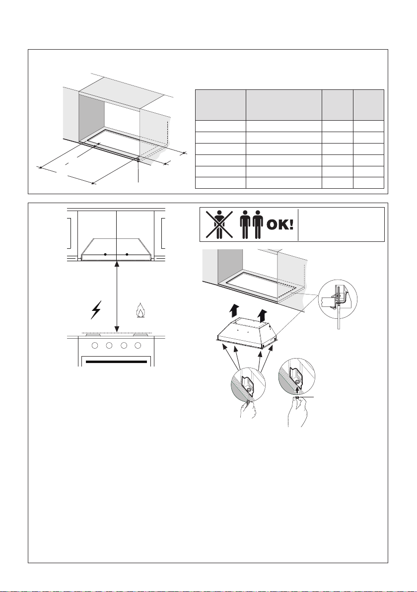
Cut out the opening in the underside of the
cabinet as shown in Figure 1a.
Installation Instructions
SECURING INSERT HOOD WITH SIDE MOUNT CLIPS
1b
It is recommend that the Insert Hood is supported by a 3/4" wood base to insure Side Mount
Clip alignment.
Minimum cabinet opening height-16". However height may vary to allow for ducting.
Install the Insert Hood into the cabinet opening, and fully engage the four spring-loaded Side
Mount Clips onto the cabinet wood base.
Next from underneath the Insert as shown in Figure A, locate the screw in each of the Side
Mount Clips.
To lock the Insert Hood into position, tighten the screw for each of four Side Mount Clips.
Next from underneath the Insert Hood Place the four plastic stoppers (10) as shown in Figure B.
Outside
Hood
Dimension
Model # X Y
30" x 19" INPL3019SSNB-B 28-5/8" 19-7/8"
36" x 19" INPL3619SSNB-B 34-3/4" 19-7/8"
36" x 22" INPL3622SSNB-B 34-3/4" 22-7/8"
42" x 19" INPL4219SSNB-B 40-3/4" 19-7/8"
48" x 19" INPL4819SSNB-B 46-3/4" 19-7/8"
48" x 22" INPL4822SSNB-B 46-3/4" 22-7/8"
Two people may be
required for installation.
2x
2x
A
B
10
Min. 24" Min. 30"
13
Installation Instructions
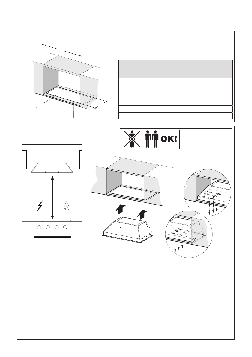
SECURING INSERT HOOD WITHOUT SIDE MOUNT CLIPS
Outside
Hood
Dimension
Model # X Y
30" x 19" INPL3019SSNB-B 28-5/8" 19-7/8"
36" x 19" INPL3619SSNB-B 34-3/4" 19-7/8"
36" x 22" INPL3622SSNB-B 34-3/4" 22-7/8"
42" x 19" INPL4219SSNB-B 40-3/4" 19-7/8"
48" x 19" INPL4819SSNB-B 46-3/4" 19-7/8"
48" x 22" INPL4822SSNB-B 46-3/4" 22-7/8"
Y
Min. 3/4
"
X
Min.13/16
"
X
Y
Min.13/16
"
Min. 3/4
"
2a
Cut out the opening in the underside of the
cabinet as shown in Figure 2a.
2b
It is recommend that the Insert Hood is supported by a 3/4" wood base.
Minimum cabinet opening height-16". However height may vary to allow for ducting.
Install the Insert Hood into the cabinet opening.
Insert Hood attaches on the short side of the cabinet using screws (purchased separately).
From inside Insert Hood as shown in Figure B and C, secure the Insert Hood with three
screws into wood support /cabinet framing.
Next from underneath the Insert Hood Place the four plastic stoppers (10) as shown in
Figure B.
Min. 24" Min. 30"
Two people may be
required for installation.
a
b
c
14
10
3
a b
4
Secure the Insert Hood with six screws (9d) on the front side as shown above in gure A.
Place the six Stopper (10) on the front side as shown above in gure B.
9d
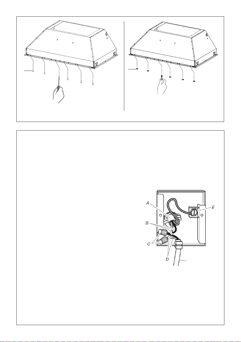
Installation of wiring connection
Remove the wiring electrical knockout using a
at-blade screwdriver. Feed the Power Supply
Cable through the electrical knockout.
Connect the Power Supply Cable to the ran-
gehood. Attach the White lead of the power
supply (A) to the White lead of the rangehood
(D) with a twist-on type wire connector. Attach
the Black lead of the power supply to the Black
lead of the rangehood (B) with a twist-on type
wire connector (C). Connect the Green (E)
(Green and Yellow) ground wire under the
Green grounding screw.
Replace the eld wiring compartment cover
and the grease lters.
Connect the ductwork to the damper and seal
all connections with duct tape.
Turn the power supply on. Turn on the blower
and light. If the rangehood does not operate,
check that the circuit breaker is not tripped
or the house fuse blown. If the unit still does
not operate, disconnect the power supply and
check that the wiring connections have been
made properly.
Reattach the eld wiring compartment cover.
Hood wiring
15
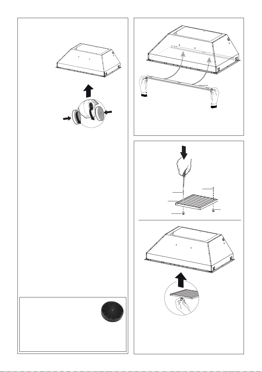
5
6
Attach each
charcoal
lter to the
black grid on
each side of
the blower.
Press the
charcoal
lter tightly
to the black
grid on the
blower side
and rotate
the lter
For Non-Ducted Recirculation
Option
Required Activated Charcoal Filter
Accessory - sku # - FILTER1
(purchased separately).
When used in recirculation mode,
to Reduce the Risk of Fire and
Shock use only conversion kit
Model FILTER 1.
clockwise (towards the front of the insert hood)
until it locks into place. Turn counterclockwise
(towards the back of the insert hood) to remove.
Replacing Activated Charcoal Filter
The Activated Charcoal Filters are not washable
and cannot be regenerated, and should be
replaced approximately every 4 months of
operation, or more frequently with heavy usage.
Remove the charcoal lter by rotating it
clockwise (backwards) until it unlocks from the
motor housing and pull o sideways.
To reinsert each charcoal lter, place up against
the side of the blower and push it inward. Then
turn the charcoal lter clockwise (forward) until it
ts into place.
7
Bae Filter
Before installing the lters (6), tighten the 2 knobs
(7) with 2 screws (9e).
Use two hands to insert and remove the lters.
1
2
8
Hook the Grease rail (8) positioning it inside
the hood. Is possible wash and reposition
inside the hood.
9e
7
6
9e
7
16
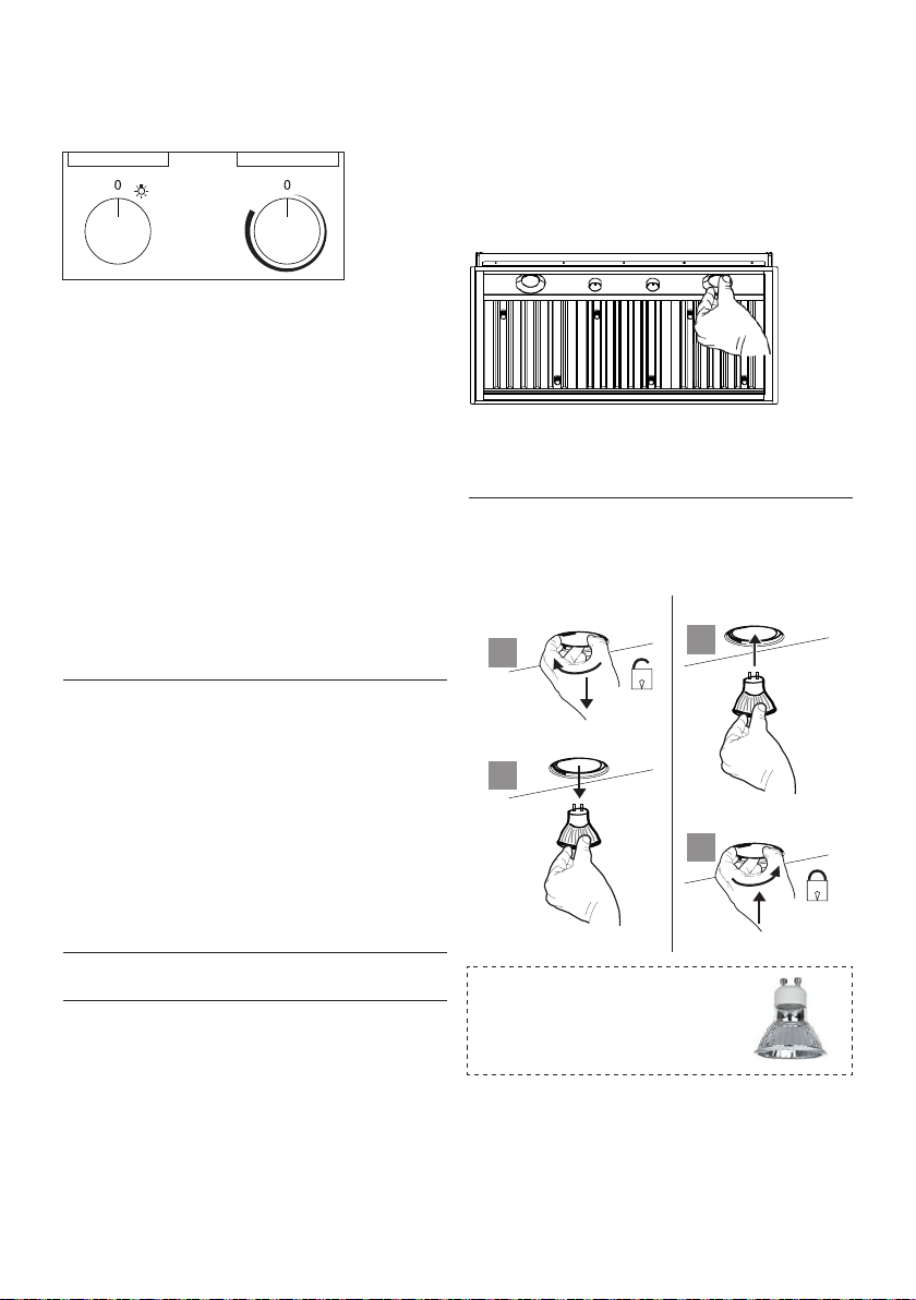
Rangehood Control Panel
The control panel is located in the center of the
hood bottom.
Light On/O Button (A)
On/O switch for the lights. Position "0" turns the
lights O, turning the switch to the right is On.
Blower On/O Button (B)
On/O switch for the blower. Move the dial to the
right to turn the blower ON and vary the speed of
the blower. Turn to the left at "0" to turn it OFF.
For Best Result
Start the rangehood several minutes before
cooking to develop proper airow. Allow the unit
to operate for several minutes after cooking is
complete to clear all smoke and odors from the
kitchen.
Cleaning
The stainless steel grease lters and grease rail
should be cleaned frequently in hot detergent
solution or washed in the dishwasher. Clean
exterior surfaces with a commercially available
stainless steel cleaner. Abrasives and scouring
agents can scratch stainless steel nishes and
should not be used to clean nished surfaces.
Make sure the grease lters are completely dry
with no water present before re-installing into
hood.
Grease rail and Grease Filter Installation /
Removal.
Remove the plastic from the lter, the knobs
need to be installed onto the lter with 2
screws to each lter.
Version 07/11 - Page 11
Light On/Off Button (A)
On/Off switch for the halogen lights. Position "0" turns the lights off,
turning the switch to the right one click is the dimmer position, and
the next click to the right is full power
Blower On/Off Button (B)
On/Off switch for the blower. Move the dial to the right to turn the
blower ON and vary the speed of the blower. Turn to the left at "0"
to turn it OFF.
For Best Result
Start the rangehood several minutes before cooking to develop proper
airflow. Allow the unit to operate for several minutes after cooking is
complete to clear all smoke and odors from the kitchen.
Cleaning
The stainless steel grease filters and grease rail should be cleaned
frequently in hot detergent solution or washed in the dishwasher.
Clean exterior surfaces with a commercially available stainless steel
cleaner. Abrasives and scouring agents can scratch stainless steel
finishes and should not be used to clean finished surfaces.
Grease rail and Grease Filter Installation / Removal
Remove the plastic from the filter, the knobs need to be installed
onto the filter with 2 screws to each filter
Install the grease rail into the back of the hood, into the slots on the
inside floor of the rear of the hood. The Grease filters should be
installed before operating the rangehood. To install the filters, use the
two knobs (in FIGURE 28) to hold the filter and insert the filter into
the front edge of the hood with the knobs facing out into the spring
loaded slot. Install the other end of the filter above the grease rail in
the back of the hood.
USE AND CARE INFORMATION
This rangehood system is designed to remove smoke, cooking vapors
and odors from the cooktop area.
Rangehood Control Panel
The control panel is located in the center of the hood bottom. The
position and function of each control button are indicated in FIGURE
27
FIGURE 28
Replacing the Halogen Lamp
Before you begin, make sure that the rangehood is turned off and
that the other lamps have had sufficient time to cool. Halogen lamps
burn extremely hot and serious injury could result from touching a hot
lamp. Press and twist the lamp to remove. Then remove the lamp
and replace with a new lamp.
WIRING DIAGRAM
This rangehood uses 45 watt PAR16
Halogen Lamps.
FIGURE 27
FIGURE 26
ALL INSTALLATIONS
1. Use a drill to install side rails on the inside rangehood walls to
line the inside hood wall with stainless, 2 and 3 in FIGURE 26 with
9a. screws, 4 screws total.
BLK
WHT
R11B41
LIGHT CONTROL
OFF / HALF LIGHT / ON
1
Y-G
A
RED
WIRING BOX
WHT
BLK
BLK
23
B
ORG
WHT
4
VLT
N
L
Y-G
LINE IN
120Vac
60Hz ~
Y-G
BLU
123
654
789
123
654
987
RED
M8 4V
120V ~
WHT
BRW
BLU
BLK
ORG
BLU
BLK
Y-G
Y-G
ON/OFF MOTOR
SPEED CONTROL
BLKBLK
BLU
123
654
789
123
654
987
RED
M8 4V
120V ~
BLU
Y-G
WHT
BRW
BLKBLK
BLU
123
654
123
654
BLK
ORG
Y-G
BLU
WHT
BLK
Y-G
WIRING BOX FOR
REMOTE BLOWER
WHT
REMOTE
BLOWER
123
654
WHT
Y-G
BLKBLK
Y-G
9a
9a
2
3
9a
9a
Gu10 self-ballasted led lamps
– listed in accordance with ul
1993/nmx-j-578/1-ance/csa
c22.2 No. 1993
Lighting unit
• Replace the lamp with a new one of the same type,
making sure that you insert the two pins properly
into the housings on the lamp holder.
a
b
a
b
Install the grease rail into the back of the hood,
into the slots on the inside oor of the rear of the
hood. The Grease lters should be installed before
operating the rangehood. To install the lters, use
the two knobs to hold the lter and insert the lter
into the front edge of the hood with the knobs
facing out into the spring loaded slot. Install the
other end of the lter above the grease rail in the
back of the hood.
A B

17
Wiring Diagram

18
January 4, 2016
FABER CONSUMER WARRANTY & SERVICE
All Faber products are warranted against any defect in materials or workmanship for the original purchaser
for a period of 1 year from the date of original purchase (requires proof of purchase). This warranty covers
labor and replacement parts. Faber, at its option, may repair or replace the product or components
necessary to restore the product to good working condition. To obtain warranty service, contact the dealer
from whom you purchased the range hood, or the local Faber distributor. If you cannot identify a local Faber
distributor, contact us at (508) 358-5353 for the name of a distributor in your area.
The following is not covered by Faber's warranty:
1. Service calls to correct the installation of your range hood, to instruct you how to use your range hood, to
replace or repair house fuses or to correct house wiring or plumbing.
2. Service calls to repair or replace range hood light bulbs, fuses or filters. Those consumable parts are
excluded from warranty coverage.
3. Repairs when your range hood is used for other than normal, single-family household use.
4. Damage resulting from accident, alteration, misuse, abuse, fire, flood, acts of God, improper installation,
installation not in accordance with electrical or plumbing codes or Faber documentation, or use of products
not approved by Faber.
5. Replacement parts or repair labor costs for units operated outside the United States or Canada, including
any non-UL or C-UL approved Faber range hoods.
6. Repairs to the hood resulting from unauthorized modifications made to the range hood.
7. Expenses for travel and transportation for product service in remote locations and pickup and delivery
charges. Faber range hoods should be serviced in the home.
THIS WARRANTY DOES NOT ALLOW RECOVERY OF INCIDENTAL OR CONSEQUENTIAL DAMAGES, INCLUDING, WITHOUT
LIMITATION, DIRECT, INDIRECT, INCIDENTAL, SPECIAL OR CONSEQUENTIAL DAMAGES, PERSONAL INJURY/WRONGFUL
DEATH OR LOST PROFITS FABER WARRANTY IS LIMITED TO THE ABOVE CONDITIONS AND TO THE WARRANTY PERIOD
SPECIFIED HEREIN AND IS EXCLUSIVE. EXCEPT AS EXPRESSLY SPECIFIED IN THIS AGREEMENT, FABER DISCLAIMS ALL
EXPRESS OR IMPLIED CONDITIONS, REPRESENTATIONS, AND WARRANTIES INCLUDING, WITHOUT LIMITATION, ANY
IMPLIED WARRANTIES OF MERCHANTABILITY OR FITNESS FOR A PARTICULAR PURPOSE
.
This warranty gives you specific legal rights that may vary from state to state.
Model#: ______________________________ Serial #: _____________________________

19
VEUILLEZ LIRE ET CONSERVER LA PRÉSENTE NOTICE AVANT DE COMMEN-
CER L'INSTALLATION DE LA HOTTE DE CUISINE
AVERTISSEMENT:-POUR RÉDUIRE LE RISQUE D'UN FEU DE GRAISSE SUR LA TABLE DE CUISSON:
a) Ne laissez jamais sans surveillance les éléments de la surface de cuisson à température élevée. Les
bouillonnements excessifs peuvent provoquer de la fumée et les débordements de graisse peuvent
s'enflammer. L'huile doit être chauffée lentement, à une température basse ou moyenne.
b) Assurez-vous de toujours mettre en marche le ventilateur de la hotte lorsque vous cuisinez à tem-
pérature élevée ou préparez un mets flambé (p.ex. crêpes Suzette, cerises jubilé, bœuf flambé).
c) Nettoyez régulièrement les ventilateurs d'aspiration. Assurez-vous de ne pas laisser de la graisse
s'accumuler sur le ventilateur ou le filtre.
d) Utilisez toujours des poêles et casseroles de la taille appropriée. Utilisez toujours des ustensiles de
cuisine de la taille adaptée à celle de l'élément chauffant.
AVERTISSEMENT: - POUR PRÉVENIR LES BLESSURES EN CAS DE FEU DE GRAISSE SUR LA TABLE DE
CUISSON, SUIVEZ LES RECOMMANDATIONS SUIVANTES*:
a) ÉTOUFFEZ LES FLAMMES à l'aide d'un couvercle hermétique, d'une plaque à biscuits ou d'un plateau
métallique, puis éteignez le brûleur. FAITES ATTENTION AUX BRÛLURES. Si le feu ne s'éteint pas
immédiatement, QUITTEZ LES LIEUX ET APPELEZ LES POMPIERS.
b) NE PRENEZ JAMAIS UNE CASSEROLE EN FLAMME - Vous pourriez vous brûler.
c) N'UTILISEZ JAMAIS DE L'EAU, ni un linge à vaisselle ou un torchon mouillé, pour éteindre le feu. Cela
pourrait provoquer une violente explosion de vapeur.
d) Utilisez un extincteur UNIQUEMENT si:
1. Vous êtes certain qu'il s'agit d'un extincteur de classe ABC et que vous connaissez bien son mode
d'emploi.
2. Le feu est de faible intensité et se limite à l'endroit où il a démarré.
3. Les pompiers ont déjà été appelés.
4. Une voie de sortie se trouve derrière vous pendant que vous éteignez les flammes
* D'après le guide «Kitchen Firesafety Tips» publié par la NFPA aux États-Unis
AVERTISSEMENT - POUR RÉDUIRE LE RISQUE D'INCENDIE OU DE CHOC ÉLECTRIQUE, n'utilisez jamais
ce ventilateur en association avec un dispositif de réglage de vitesse à semi-conducteurs.
AVERTISSEMENT - POUR RÉDUIRE LES RISQUES D'INCENDIE, DE CHOC ÉLECTRIQUE OU DE BLESSURE
CORPORELLE, RESPECTEZ LES INSTRUCTIONS SUIVANTES :
a. Utilisez cet appareil uniquement de la façon prévue par le fabricant. Pour toute question, commu-
niquez avec le fabricant.
b. Avant de procéder à l'entretien ou au nettoyage de l'appareil, coupez l'alimentation au niveau du
panneau électrique et verrouillez-le pour vous assurer que l'électricité n'est pas rétablie acciden-
tellement.
S'il n'est pas possible de verrouiller le dispositif d'interruption de l'alimentation, affichez de façon
ferme et bien visible un avis de danger, par exemple à l'aide d'une étiquette sur le panneau.
ATTENTION : Destiné à un usage de ventilation générale uniquement. N'utilisez pas ce dispositif pour
l'aspiration de vapeurs ou de matériaux dangereux ou explosifs.
AVERTISSEMENT - POUR RÉDUIRE LES RISQUES D'INCENDIE, DE CHOC ÉLECTRIQUE OU DE BLESSURE
CORPORELLE, RESPECTEZ LES INSTRUCTIONS SUIVANTES:
1. L'installation et le branchement électrique doivent être réalisés par un technicien qualifié et
conformément à tous les codes et normes en vigueur, incluant ceux concernant la construction
à l'épreuve du feu.
2. Afin de garantir une combustion et une évacuation adéquates des gaz par les conduites de la
cheminée des appareils à combustion, une bonne aération est nécessaire pour éviter le refou-
lement. Respectez les lignes directrices fournies par le fabricant du matériel chauffant, ainsi que
les normes de sécurité comme celles publiées par la National Fire Protection Association (NFPA)

20
et la American Society for Heating, Refrigeration and Air Conditioning Engineers (ASHRAE) aux
États-Unis, ainsi que les codes en vigueur dans votre région.
3. Lorsque vous faites une ouverture ou percez dans un mur ou le plafond, veillez à ne pas endom-
mager les fils électriques ou d'autres dispositifs cachés.
4. Les ventilateurs canalisés doivent toujours être raccordés à l'extérieur.
TOUTE OUVERTURE DANS LE MUR OU LE PLANCHER À PROXIMITÉ DE LA HOTTE
DOIT ÊTRE SCELLÉE.
Un espace libre d'au moins 24" est requis entre le bas de la hotte et la surface de cuisson ou le comptoir.
Cette hotte a été homologuée par l'UL à cette distance de la surface de cuisson.
L’espace libre minimal requis peut-être plus grand, selon la réglementation en matière de construction de
votre région. Pour les cuisinières à gaz et les cuisinières combinées, un espace minimal de 30" est recommandé
et pourrait être exigé.
Les armoires suspendues de chaque côté de l'appareil doivent se trouver à au moins 18" de la surface de
cuisson ou du comptoir. Consultez la notice d'installation de la surface de cuisson ou de la cuisinière fournie
par le fabricant avant de pratiquer des ouvertures.
INSTALLATION DANS UNE MAISON MOBILE L'installation de cette hotte doit être conforme à la Partie 3280
de la norme Manufactured Home Construction and Safety Standards, Title 24 CFR (précédemment la partie
280 de la norme Federal Standard for Mobile Home Construction and Safety, Title 24, HUD). Consultez la
fiche technique électrique.
CRITÈRES DE VENTILATION
Déterminez quelle méthode de ventilation est mieux adaptée à votre application. Les conduits peuvent
passer par le mur ou le toit.
Pour garantir une meilleure efficacité, la longueur des conduits et le nombre de coudes doivent être le plus
limités que possible. Le diamètre des conduits devrait être uniforme. N'installez pas deux coudes ensemble.
Utilisez un ruban pour canalisations afin de sceller tous les joints du système de conduits. Utilisez un calfeutrage
pour sceller les ouvertures dans le mur extérieur ou le plancher, autour du clapet.
Il n'est pas recommandé d'utiliser des conduits exibles. Les conduits exibles provoquent une contre-pres-
sion et de la turbulence qui diminuent grandement l'ecacité de l'appareil.
Assurez-vous que l'espace libre dans le mur ou le plancher est suffisant pour le conduit d'évacuation avant
de pratiquer les ouvertures. Ne coupez jamais une poutre ou un chevron, sauf si c'est absolument nécessaire.
S'il s'avère nécessaire de couper une poutre ou un chevron, la construction d'un renforcement est requise.
AVERTISSEMENT - Pour réduire le risque d'incendie, utilisez uniquement des conduits métalliques.
ATTENTION - Pour réduire le risque d'incendie et pour évacuer adéquatement l'air, assurez-vous de
raccorder les conduits à l'extérieur – Ne diffusez pas l'air d'évacuation dans des espaces à l'intérieur
des murs ou du plafond, ou encore à l'intérieur d'un grenier, d'une galerie technique ou d'un garage.

21
FICHE TECHNIQUE ÉLECTRIQUE
Une alimentation de courant alternatif de 120 volt à 60 Hz est requise sur un circuit à fusible distinct
de 15 ampères. Il est recommandé d'installer un fusible temporisé ou un disjoncteur. Le fusible doit
être calibré conformément aux codes en vigueur pour les caractéristiques nominales électriques
de l'appareil, indiquées sur la plaque signalétique située à l'intérieur de l'appareil, à proximité du
compartiment des câblages externes.
INSTALLATION ÉLECTRIQUE AVEC BOÎTIER DE CÂBLAGES
CET APPAREIL DOIT ÊTRE UNIQUEMENT BRANCHÉ À L'AIDE DE FILS DE CUIVRE. Le calibre des ls
doit être conforme aux critères de la dernière édition du National Electrical Code, de l'ANSI/NFPA
70 et de l'ensemble des codes et réglementations en vigueur. Le calibre des ls et les connexions
doivent être adaptés aux caractéristiques nominales de l'appareil. Il est possible de se procurer un
exemplaire des normes indiquées ci-dessus en communiquant avec :
National Fire Protection Association
Batterymarch Park
Quincy, Massachusetts 02269 (États-Unis)
Cet appareil devrait être branché directement au sectionneur à fusible (ou au disjoncteur) par un
câble exible de cuivre avec blindage ou gaine non métallique. Laissez un peu de jeu dans le câble
pour permettre le déplacement de l'appareil si des travaux d'entretien s'avéraient nécessaires. Un
raccord de conduit homologué par l'UL de 1/2 " doit être installé aux deux extrémités du câble
d'alimentation (au niveau de l'appareil et de la boîte de liaison).
Lors de la réalisation du branchement électrique, réalisez un trou de 1 1/4 " dans le mur. S'il s'agit
d'un trou dans le bois, il doit être poncé pour le rendre lisse. S'il s'agit d'un trou dans le métal, un
passe-ls est requis.
• Le système de ventilation DOIT déboucher à l'extérieur.
• NE FAITES PAS déboucher les conduits dans un grenier ou un autre endroit fermé.
• N'UTILISEZ PAS un clapet de sécheuse mural de 4 po.
• Il n'est pas recommandé d'utiliser des conduits flexibles.
• N'ENTRAVEZ PAS le flux de l'air de combustion et de ventilation.
• Le non-respect des exigences en matière de ventilation pourrait entraîner un incendie.
AVERTISSEMENT
!
22
• Une mise à la terre électrique est requise pour cette hotte.
• N'UTILISEZ PAS un tuyau d'eau froide pour la mise à la terre si celui-ci est branché par des
joints en plastique, par des rondelles non métalliques ou d'autres matériaux.
• N'UTILISEZ PAS une conduite de gaz pour la mise à la terre.
• N'INSTALLEZ PAS un fusible sur le circuit neutre ou le circuit de mise à la terre. La présence
d'un fusible dans le circuit neutre ou de mise à la terre peut entraîner un choc électrique.
• Consultez un électricien qualié si vous n'êtes pas certain de la mise à la terre de la hotte.
• Le non-respect des exigences de la che technique électrique pourrait entraîner un incendie.
AVERTISSEMENT
!
Avertissement de la proposition 65 de l'État de Californie (US seulement)
ATTENTION
Ce produit contient des produits chimiques connus de l'État de Californie pour causer le
cancer et des malformations congénitales ou d'autres problèmes de reproduction.
Pour plus d'informations, visitez www.P65Warnings.ca.gov
23
DIMENSIONS DE LA HOTTE
12-5/16"
10-13/16"
18-11/16"
21-1/4" (A1) - 22-1/2" (A2)
28-9/16" (A3) - 34-9/16" (A4)
7-15/16"
1/2"
3-1/8"
11"
28-1/2" (A1) - 34-1/2" (A2)
40-9/16" (A3) - 46-9/16" (A4)
29-1/2" (A1) - 35-1/2" (A2)
41-9/16" (A3) - 47-9/16" (A4)
1/2"
20-11/16"
19-11/16"
15-5/16"
10-13/16"
18-11/16"
22-1/2" (A1) - 34-9/16" (A2)
7-15/16"
1/2"
3-1/8"
11"
34-1/2" (A1) - 46-9/16" (A2)
35-1/2" (A1) - 47-9/16" (A2)
1/2"
23-11/16"
22-11/16"
Légende Modèle #
A1 INPL3019SSNB-B
A2 INPL3619SSNB-B
A3 INPL4219SSNB-B
A4 INPL4819SSNB-B
Légende Modèle #
A1 INPL3622SSNB-B
A2 INPL4822SSNB-B
24
PIÈCES PRINCIPALES
Composants
Réf. Qté Product Components
1 1 Bâti de la hotte avec : Commandes, Éclairage,
Filtres, Ventilateur.
4 2 Garniture avant/arrière
5 2 Garniture gauche/droite
6 2 Filtresàgraisse(30")
6 3 Filtresàgraisse(36"-42")
6 4 Filtresàgraisse(48")
7 4 Boutonsdesltres(30")
7 6 Boutonsdesltres(36"-42")
7 8 Boutonsdesltres(48")
8 1 Gouttière
10 10 Obturateur
Réf. Qté Composants d'installation
9c 14 Visd’installation(1/8"x1/4")
9d 6 Visd’installation(1/8"x5/16")
9e 4 Visdesltresàgraisse(3/16"x5/16"-30")
9e 6 Visdesltresàgraisse(5/32"x5/16"-36"-42")
9e 8 Visdesltresàgraisse(5/32"x5/16"-48")
Qté Documentation
1 Instruction Manual
Filtre à charbon actif, n°
d'article FILTER1
Filtre à charbon actif, n°
d'article FILTER1LL
Ventilateur interne 300 PCM, n°
d'article IB300
Ventilateur interne 600 PCM PRO, n°
d'article IB600
Ventilateur interne 1 200 PCM PRO,
n° d'article IB1200
Ventilateur à distance 900 PCM, n°
d'article RB900
Ventilateur à distance 1 200 PCM, n°
d'article RB1200
Trousse de raccord de ventilateur en
ligne, n° d'article INLBKIT
1
9c
9c
5
8
7
5
4
4
6
9d
10
9e
Accessoires
disponibles
25
ATTENTION —Pour réduire le risque d’incendie ou de choc électrique, installez cette hotte uniquement avec
un ventilateur à distance fabriqué par Faber (modèles RB900 et RB1200) ou avec un ventilateur interne fabri-
qué par Faber (modèles IB300, IB600 ou IB1200), avec la trousse accessoire INLBKIT achetée séparément. Si
vous utilisez un ventilateur en ligne ou à distance générique, il doit avoir une valeur nominale maximale de 4,2
A et être compatible avec une commande de variation de vitesse à semi-conducteur; il doit aussi être utilisé
avec la trousse accessoire INBKLIT, achetée séparément.
Pour le modèle Inca 30", il est recommandé d’utiliser des ventilateurs ayant une ca-
pacité MAXIMALE de 600 PCM.
INSTALLATION
COMBINAISONS CAPOT ET KITS DE MOTEUR
Version 07/11 - Page 6
INSTALLATION
COMBINATIONS HOOD AND MOTOR KITS
CHOOSE A BLOWER FOR YOUR HOOD
After choosing the hood width and depth for your cooking
needs, next choose the type of blower appropriate for
your cooking.
NOTE: no other blower is
compatible with this hood, except for the
kits below.
# IB300 - Internal Blower Kit 300 cfm
# IB600 - Internal Blower Kit 600 cfm
# IB1200 - Internal Blower Kit 1200 cfm
# RB900 - Remote Blower Kit 900 cfm
# RB1200 - Remote Blower Kit 1200 cfm
# INLBKIT - In Line Blower Kit
(supply own in-line blower)
OPTIONAL ACCESSORIES AVAILABLE
• *Charcoal Filter
* it is highly recommended that professional style cooking always be
vented to the outside; for recirculating installations only, some ductwork is
required to exhaust the unit out of the cabinet. Replace as needed with the
same model
part # FILTER1
NOTE: The charcoal filter kit for use with the 300 / 600
cfm internal blower kit ONLY
CAUTION - To reduce risk of fire and electric shock, install this rangehood only with: Remote blower manufacturer by Faber
models RB900 and RB1200 or Integral blower manufactured by Faber models IB300 or IB600 or IB1200 or with INLBKIT and
generic in-line blower rated max 4.2 A suitable for use with solid state variable speed control
INLBKIT
26
1. Installez le plat B (Figure 2) qui est venu avec le
kit interne de ventilateur, sur le rangehood. Utilisez
9 vis fournies avec le kit de ventilateur.
5
5
4
4
9c
Version 07/11 - Page 8
INSTALLATION WITH IB300 / IB600 INTERNAL BLOWER (300
, 600 cfm)
1. Install the Plate B (FIGURE 8) which came with the internal
blower kit, on top of the rangehood with the hole closer to the back
of the hood. Use 9 screws supplied with the blower kit
6. (see FIGURE 13) Remove the cover from the field wiring
compartment with a phillips screwdriver. Feed the Power Supply
Cable through the electrical knockout. Connect the Power Supply
Cable to the rangehood cable. Attach the White lead of the power
supply to the White lead of the rangehood with a twist-on type wire
connector. Attach the Black lead of the power supply to the Black
lead of the rangehood with a twist-on type wire connector. Attach
the Power Supply Cable grounding lead to the green screw provided.
Replace the cover.
7. Connect the ductwork to the damper and seal all connections with
duct tape. Install the grease filters and grease rail. (see page 11 for
instructions)
8. Turn the power supply on. Turn on the blower and light. If the
rangehood does not operate, check that the circuit breaker is not
tripped or the house fuse blown. If the unit still does not operate,
disconnect the power supply and check that the wiring connections
have been made properly.
9. CONTINUE TO PAGE 11
FIGURE 8
2. Remove the white plastic covering and install the 4 side trim
pieces to the outside of the hood using (16) part 9b screws, see
the side rail installation in (FIGURE 9).
FIGURE 9
5. Attach the hood to the cabinet using (12) 9c. screws to the
cabinet. FIGURE 12
FIGURE 12
FIGURE 10
3. Install the motor kit into the hood using the 2 screws supplied
with the motor kit into the back of the hood. (FIGURE 10)
4. Connect the wire that comes with the motor kit from the side
of the motor to the connection on the inside of the light panel in
the hood. The 9 hole end of the wire is installed in the motor, the
6 hole end is connected to the light panel (FIGURE 11)
FIGURE 11
FIGURE 13
B
INSTALLATIONS AVEC RECIRCULATION
LA VENTILATION ASSOCIÉE À UNE CUISINE DE TYPE PROFESSIONNEL DEVRAIT TOUJOURS
ÊTRE ÉVACUÉE À L’EXTÉRIEUR. Pour les installations avec recirculation (Figure 1), il est nécessaire
d'installer des ltres à charbon. Retirez tous les ltres à graisse et mettez-les à part. Posez un ltre à
charbon à chaque extrémité du ventilateur. Chaque ltre à charbon se xe à une grille sur le côté du
ventilateur. Faites tourner le ltre dans le sens des aiguilles d'une montre pour l'installer et dans le sens
contraire des aiguilles d'une montre pour l'enlever (Figure 1A). Remettez tous les ltres à graisse en
place. Les installations avec recirculation nécessitent l’installation de canalisations pour diriger l’air à
l’extérieur de l’armoire ou de l’habillage sur mesure, par le haut, l’avant ou le côté, ou encore par le
côté/l’avant du parement, et de retour dans la cuisine. Installez un conduit métallique vertical d’au moins
15" (Figure 1) sur la sortie d’air. Faites passer le conduit verticalement et xez-le à l'ouverture adéquate
pratiquée au sommet précédemment ou sur le côté de l'armoire ou du parement. L’utilisation d’une grille
métallique pour couvrir le conduit est également recommandée. La canalisation ne doit pas se terminer
à l’intérieur de l’armoire ou de l’habillage sur mesure.
2. Retirez la protection blanche de plastique et
installez les 4 pièces de garniture des côtés (4-5)
sur l’extérieur de la hotte à l’aide des 14 vis (9c).
Consultez le schéma d’installation des garnitures
à la (Figure 3).
INSTALLATION AVEC LE VENTILATEUR IB300 / IB600 INTERNE (300, 600 cfm)
FIGURE 2
FIGURE 3
POUR TOUTES LES INSTALLATIONS ENLEVEZ TOUT LE REVÊTEMENT DE PROTECTION
EN PLASTIQUE BLANC DU CAPOT, DES RAILS LATÉRAUX, DE L'ÉQUILIBRE, DES RAILS DE
GRAISSE ET DES FILTRES DE GRAISSE.
FIGURE 1
Version 07/11 - Page 15
PLAN DU CONDUIT
Pour assurer que le ventilateur marche le mieux,
le conduit doit être aussi court et aussi droit que
possible.
Le ductrun ne devrait pas dépasser 35 pieds
équivalents si canalisé utilisant le minimum exigé
de 6" ; conduit rond. Pour 10" ; la canalisation
ronde avec le moteur 1200 de cfm ou le ventilateur
interne de 900/1200 extérieurs, emploient 55 pieds
équivalents. Calculez la longueur de la canalisation
en ajoutant les pieds équivalents sur le SCHÉMA 5
pour chaque morceau de conduit dans le système
qu'un exemple est donné sur le SCHÉMA 6.
Pour de meilleurs résultats, ne pas utiliser plus
de trois coudes de 90
˚
. S’assurer qu’il y ait un
minimum de 24 po de conduit droit entre les
coudes si l’on utilise plus d’un coude. Ne pas
installer deux coudes ensemble.
9 Feet Straight Duct
2 - 90˚ Elbows
Wall Cap
Total System
9.0 feet
10.0 feet
0.0 feet
19.0 feet
3.0 feet
5.0 feet
12.0 feet
0.0 feet
45˚ Elbow
90˚ Elbow
90˚ Flat Elbow
Wall Cap
INSTALLATION POUR RECIRCULATION D'AIR
Un nécessaire des deux Filtres au Charbon (FIGURE 4A) est requis pour ce type d'installation. Installation pour recirculaton d'air requis
conduit pour divertir l'air à l'extérieur de l'armoire. Ne la conduit terminez pas dan l'armoire.
FIGURE 4 - INSTALLATION POUR RECIRCULATION D'AIR
le plafond
le plafond
inca pro 30
FIGURE 4A
conduit
hotte
encastrable
hotte
encastrable
conduit
inca pro 30
FIGURE 2
FIGURE 3
FAITES VOS COUPES-CIRCUIT
1. Démontez et déplacez la gamme libre de l'ouverture de coffret pour fournir un accès plus
facile au coffret ou au capot supérieur de coutume. Mettez un revêtement de protection
épais et au-dessus de cooktop, placer-dans la gamme ou la partie supérieure du comptoir
pour se protéger contre les dommages ou la saleté.
2. Déterminez et faites tout le nécessaire coupe dedans le mur et/ou le plafond pour la
canalisation. Installez la canalisation avant le rangehood.
3. Déterminez l'endroit approprié pour le câble d'alimentation d'énergie. Employez un 1 1/4"
; Peu de foret pour faire ce trou. Installez le câble. Employez le calfeutrage pour sceller
autour du trou. Ne rétablissez pas le courant jusqu'à ce que l'installation soit complète.
4. Choisissez le coup dehors trouent pour enlever pour installer le cable électrique. Utilisez
un tournevis pour se casser outre du coup couvrant dehors. (le SCHÉMA 7 montre à
l'intérieur de la boîte et de l'extérieur de câblage)
FIGURE 7
POUR TOUTES LES INSTALLATIONS ENLEVEZ TOUT LE REVÊTEMENT DE
PROTECTION EN PLASTIQUE BLANC DU CAPOT, DES RAILS LATÉRAUX, DE
L'ÉQUILIBRE, DES RAILS DE GRAISSE ET DES FILTRES DE GRAISSE
FIGURE 1A
27
3. Installez la trousse du moteur dans la hotte en
utilisant les 2 vis fournies avec la trousse dans l’ar-
rière de la hotte (Figure 4).
5. Raccordez le conduit au registre et scellez
toutes les connexions à l'aide de ruban.
D
FIGURE 5
FIGURE 6
A
6. Avant d’installer la hotte, posez le registre A (qui
se trouve à l’intérieur de la trousse du ventilateur
interne 300 PCM, n° d'article IB300 ou du venti-
lateur interne 600 PCM PRO, n° d'article IB600)
(Figure 6).
FIGURE 4
Extrémité à 9 orices
Extrémité à 9
orices
Extrémité
à 6
orices
4. Branchez le câble de branchement D (qui se
trouve à l’intérieur de la trousse du ventilateur
interne 300 PCM, n° d'article IB300 ou du venti-
lateur interne 600 PCM PRO, n° d'article IB600).
Branchez l’extrémité à 6 orices au boîtier de
connexion et l’extrémité à 9 orices au moteur (Fi-
gure 5).
Extrémité à 9 orices
Extrémité à 6 orices
28
INSTALLATION AVEC LE VENTILATEUR IB1200
INTERNE (cfm 1200)
1. Installez la plaque de canalisation B (Figure 7)
fournie dans la trousse du ventilateur, sur le haut
de la hotte, avec les orices à proximité de l’avant.
Utilisez les 9 vis fournies avec la trousse du ven-
tilateur.
2. Retirez la protection blanche de plastique et
installez les 4 pièces de garniture des côtés (4-5)
sur l’extérieur de la hotte à l’aide des 14 vis (9c).
Consultez le schéma d’installation des garnitures
à la (Figure 8).
3. Fixez la parenthèse de ventilateur à l’intérieur
de la hotte avec 2 vis sur le dessus de la hotte et
2 à l’arrière, le tout fourni avec la trousse du venti-
lateur (Figure 9).
5
5
4
4
9c
Version 07/11 - Page 9
INSTALLATION WITH IB1200 INTERNAL BLOWER (1200 cfm)
1. Install the Plate B (FIGURE 14) which came with the internal
blower kit, on top of the rangehood with the holes located closer to
the front. Use 9 screws supplied with the blower kit
2. Remove the white plastic covering and Install the 4 side trim
pieces to the outside of the hood using (16) part 9b screws, see
the side rail installation in (FIGURE 15).
3. Attach the blower bracket divider inside the hood, with the 2
screws into the top of the hood and 2 screws into the back, all
supplied with the blower kit (FIGURE 16)
FIGURE 16
FIGURE 17
4. Install the 2 motor kits into the sides of the blower bracket using
the 4 screws supplied with the motor kit. (FIGURE 17)
5. Connect the wire (FIGURE 18) that comes with the motor kit
from the side of the two motors to the connection on the inside
of the light panel in the hood. The two - 9 hole ends of the wire
are installed in the two motors, the 6 hole end is connected to
the light panel (FIGURE 11 on the previous page)
FIGURE 15
FIGURE 18
FIGURE 19
6. Install the 2 dampers on top of the hood. If you want one 10"
round duct to come out of the top of the hood, use the transition
piece (FIGURE 19) that comes with the motor kit and install with
four screws. If you want to use 2 seperate 6" round ducts, do not
use the transition.
7. Attach the hood to the cabinet using (12) 9c. screws to the
cabinet. FIGURE 20
8. Follow steps 6 - 9 on the previous page to connect ducting,
wiring, and test the electrical connection.
FIGURE 14
FIGURE 20
B
4. Installez les 2 kits de moteur sur les côtés de la
parenthèse de ventilateur utilisant les 4 vis four-
nies avec le kit de moteur (Figure 10).
7. Suivez la procédure décrite à l’étape 4 de la page
13 pour le raccord de la canalisation, les branche-
ments et l’essai de la connexion électrique.
Version 07/11 - Page 9
INSTALLATION WITH IB1200 INTERNAL BLOWER (1200 cfm)
1. Install the Plate B (FIGURE 14) which came with the internal
blower kit, on top of the rangehood with the holes located closer to
the front. Use 9 screws supplied with the blower kit
2. Remove the white plastic covering and Install the 4 side trim
pieces to the outside of the hood using (16) part 9b screws, see
the side rail installation in (FIGURE 15).
3. Attach the blower bracket divider inside the hood, with the 2
screws into the top of the hood and 2 screws into the back, all
supplied with the blower kit (FIGURE 16)
FIGURE 16
FIGURE 17
4. Install the 2 motor kits into the sides of the blower bracket using
the 4 screws supplied with the motor kit. (FIGURE 17)
5. Connect the wire (FIGURE 18) that comes with the motor kit
from the side of the two motors to the connection on the inside
of the light panel in the hood. The two - 9 hole ends of the wire
are installed in the two motors, the 6 hole end is connected to
the light panel (FIGURE 11 on the previous page)
FIGURE 15
FIGURE 18
FIGURE 19
6. Install the 2 dampers on top of the hood. If you want one 10"
round duct to come out of the top of the hood, use the transition
piece (FIGURE 19) that comes with the motor kit and install with
four screws. If you want to use 2 seperate 6" round ducts, do not
use the transition.
7. Attach the hood to the cabinet using (12) 9c. screws to the
cabinet. FIGURE 20
8. Follow steps 6 - 9 on the previous page to connect ducting,
wiring, and test the electrical connection.
FIGURE 14
FIGURE 20
B
FIGURE 7
FIGURE 8
FIGURE 9
FIGURE 10
5. Branchez le câble de branchement D (qui se
trouve à l’intérieur de la trousse du ventilateur
interne 1 200 PCM PRO, n° d'article IB1200).
Branchez l’extrémité à 6 orices (A) au boîtier
de connexion et l’extrémité à 9 orices (B-C) aux
deux moteurs (Figure 11).
FIGURE 11
D
6. Installez les 2 registres (A) sur le dessus de la
hotte (à l’intérieur de la trousse du ventilateur interne
1 200 PCM PRO, n° d'article IB1200). Autrement,
installez le passage de la canalisation de 10" (E) (qui
se trouve à l’intérieur de la trousse du ventilateur in-
terne 1 200 PCM PRO, n° d'article IB1200) et instal-
lez-le à l’aide de quatre vis (Figure 12).
Version 07/11 - Page 9
INSTALLATION WITH IB1200 INTERNAL BLOWER (1200 cfm)
1. Install the Plate B (FIGURE 14) which came with the internal
blower kit, on top of the rangehood with the holes located closer to
the front. Use 9 screws supplied with the blower kit
2. Remove the white plastic covering and Install the 4 side trim
pieces to the outside of the hood using (16) part 9b screws, see
the side rail installation in (FIGURE 15).
3. Attach the blower bracket divider inside the hood, with the 2
screws into the top of the hood and 2 screws into the back, all
supplied with the blower kit (FIGURE 16)
FIGURE 16
FIGURE 17
4. Install the 2 motor kits into the sides of the blower bracket using
the 4 screws supplied with the motor kit. (FIGURE 17)
5. Connect the wire (FIGURE 18) that comes with the motor kit
from the side of the two motors to the connection on the inside
of the light panel in the hood. The two - 9 hole ends of the wire
are installed in the two motors, the 6 hole end is connected to
the light panel (FIGURE 11 on the previous page)
FIGURE 15
FIGURE 18
FIGURE 19
6. Install the 2 dampers on top of the hood. If you want one 10"
round duct to come out of the top of the hood, use the transition
piece (FIGURE 19) that comes with the motor kit and install with
four screws. If you want to use 2 seperate 6" round ducts, do not
use the transition.
7. Attach the hood to the cabinet using (12) 9c. screws to the
cabinet. FIGURE 20
8. Follow steps 6 - 9 on the previous page to connect ducting,
wiring, and test the electrical connection.
FIGURE 14
FIGURE 20
B
FIGURE 12
E
B) Extrémité à 9 orices
B) Extrémité
à 9 orices
C) Extrémité
à 9 orices
C) Extrémité à 9 orices
A) Extrémité à 6 orices
A) Extrémité à 6 orices
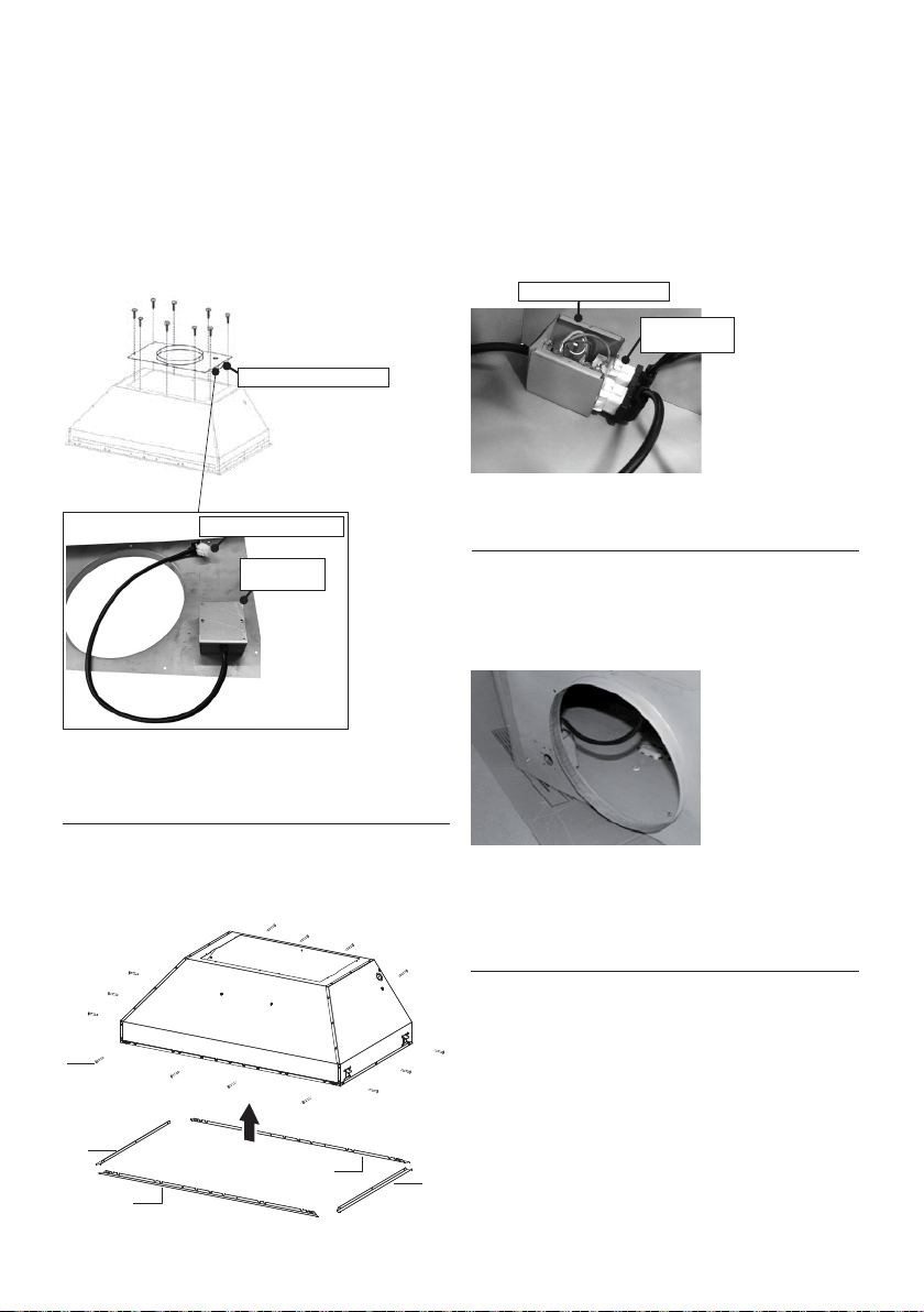
29
5
5
4
4
9c
INSTALLATION AVEC LE VENTILATEUR À DISTANCE
(RB900 / RB1200 OU VENTILATEUR INTÉGRÉ (INLBKIT)
NOTE : SUIVEZ LES INSTRUCTIONS INCLUSES AVEC LE VENTILATEUR À DISTANCE
POUR INSTALLER LE VENTILATEUR SUR L'EXTÉRIEUR DE VOTRE MAISON.
1. Installez sur le dessus de la hotte la plaque B avec
le deuxième boîtier de connexion (Figure 13) fournie
avec la trousse du ventilateur à distance. Utilisez les
9 vis fournies avec la trousse du ventilateur. Procédez
à l’ouverture de l’orice à défoncer sur le dessus de
la plaque.
2. Retirez la protection blanche de plastique et
installez les 4 pièces de garniture des côtés (4-5) sur
l’extérieur de la hotte à l’aide des 14 vis (9c). Consultez
le schéma d’installation des gouttières latérales à la
(Figure 14).
FIGURE 14
3. Branchez le câble sortant du 2e boîtier de connexion
à l’extrémité à 6 orices du 1er boîtier de connexion.
Brancher le câble sortant du boîtier noir de la carte
électronique à l’extrémité à 9 orices du 1er boîtier de
connexion (Figure 15).
Version 07/11 - Page 10
INSTALLATION WITH REMOTE BLOWER (RB900 / RB1200)
OR IN-LINE BLOWER (INLBKIT)
NOTE: FOLLOW THE INSTRUCTIONS INCLUDED WITH THE
REMOTE BLOWER TO INSTALL THE BLOWER ON THE
OUTSIDE OF YOUR HOME
.
1. Install the Plate B (FIGURE 21) which came with the remote
blower kit, on top of the rangehood. Use 9 screws supplied with
the blower kit. Remove the electrical knockout hole on top of the
plate.
2. Remove the white plastic covering and Install the 4 side trim
pieces to the outside of the hood using (16) part 9b screws, see
the side rail installation in (FIGURE 22).
FIGURE 23
FIGURE 24
4. Feed the remote blower cable thru the knockout hole in step 1
(FIGURE 24). Connect the power supply cable from the remote
blower to the wiring box on the top ducting plate of the hood. Use
step 6 on page 8 and the diagram on page 8 (FIGURE 13)
5. Attach the hood to the cabinet using (12) 9c. screws to the
cabinet. FIGURE 25
6. Follow steps 6 - 9 on page 8 to connect ducting, wiring, and
test the electrical connection. Use the wiring box connected to
the inside wall of the hood which connects to the home power
supply thru the knockout on the side of the hood.
FIGURE 21
FIGURE 22
3. Connect the wire coming out of the wiring box on the top duct
plate to the light panel 6 hole slot connector on the front inside
of the hood (FIGURE 23)
FIGURE 25
B
4. Faites passer le câble du ventilateur à distance
dans l’orice à défoncer de l’étape 1 (Figure 13, 16).
Branchez ce câble du ventilateur à distance au 2e
boîtier de connexion sur la surface inférieure de la
plaque B.
5. Suivez les étapes 4 à la page 13 pour relier la
canalisation, câblage, et examinez le raccordement
électrique. Utilisez la boîte de câblage reliée au
mur intérieur du capot qui se relie à l'alimentation
d'énergie à la maison par le coup de grâce du côté
du capot.
FIGURE 16
Version 07/11 - Page 10
INSTALLATION WITH REMOTE BLOWER (RB900 / RB1200)
OR IN-LINE BLOWER (INLBKIT)
NOTE: FOLLOW THE INSTRUCTIONS INCLUDED WITH THE
REMOTE BLOWER TO INSTALL THE BLOWER ON THE
OUTSIDE OF YOUR HOME
.
1. Install the Plate B (FIGURE 21) which came with the remote
blower kit, on top of the rangehood. Use 9 screws supplied with
the blower kit. Remove the electrical knockout hole on top of the
plate.
2. Remove the white plastic covering and Install the 4 side trim
pieces to the outside of the hood using (16) part 9b screws, see
the side rail installation in (FIGURE 22).
FIGURE 23
FIGURE 24
4. Feed the remote blower cable thru the knockout hole in step 1
(FIGURE 24). Connect the power supply cable from the remote
blower to the wiring box on the top ducting plate of the hood. Use
step 6 on page 8 and the diagram on page 8 (FIGURE 13)
5. Attach the hood to the cabinet using (12) 9c. screws to the
cabinet. FIGURE 25
6. Follow steps 6 - 9 on page 8 to connect ducting, wiring, and
test the electrical connection. Use the wiring box connected to
the inside wall of the hood which connects to the home power
supply thru the knockout on the side of the hood.
FIGURE 21
FIGURE 22
3. Connect the wire coming out of the wiring box on the top duct
plate to the light panel 6 hole slot connector on the front inside
of the hood (FIGURE 23)
FIGURE 25
B
FIGURE 13
2
e
boîtier de connexion
FIGURE 15
1
e
boîtier de connexion
2
e
boîtier de
connexion
Extrémité à 6 orices
Extrémité à 6
orices

30
Y
Min. 3/4
"
X
Min.13/16
"
X
Y
Min.13/16
"
Min. 3/4
"
1a
Pratiquez l'ouverture sur la face inférieure de
l'armoire, comme illustré à la Figure 1.
Notice d'installation
INSTALLATION DE LA HOTTE ENCASTRABLE AVEC LES FIXATIONS LATÉRALES DE MONTAGE
1b
On recommande que la hotte encastrable s'appuie sur une base de bois de 3/4" pour garantir
l’alignement des xations latérales de montage.
Hauteur minimum de l’ouverture de l’armoire : 16". La hauteur peut toutefois varier pour per-
mettre la canalisation.
Installez la hotte encastrable dans l’ouverture de l’armoire, et engagez fermement les quatre
xations latérales de montage à ressort sur la base de bois de l’armoire.
À partir du dessous de la hotte, posez ensuite la vis de chacune des xations latérales de
montage, comme illustré sur la Figure A.
Pour bloquer la hotte encastrable en place, serrez la vis pour chacune des quatre xations
latérales de montage.
À partir du dessous de la hotte encastrable, placez ensuite les quatre obturateurs de plastique
(10), comme illustré sur la Figure B.
Dimension
extérieure
de hotte
Modèle # X Y
30" x 19" INPL3019SSNB-B 28-5/8" 19-7/8"
36" x 19" INPL3619SSNB-B 34-3/4" 19-7/8"
36" x 22" INPL3622SSNB-B 34-3/4" 22-7/8"
42" x 19" INPL4219SSNB-B 40-3/4" 19-7/8"
48" x 19" INPL4819SSNB-B 46-3/4" 19-7/8"
48" x 22" INPL4822SSNB-B 46-3/4" 22-7/8"
Deux personnes
pourraient être requises
pour l’installation.
2x
2x
A
B
10
Min. 24" Min. 30"

31
Notice d'installation
INSTALLATION DE LA HOTTE ENCASTRABLE SANS FIXATIONS LATÉRALES DE MONTAGE
Dimension
extérieure
de hotte
Modèle # X Y
30" x 19" INPL3019SSNB-B 28-5/8" 19-7/8"
36" x 19" INPL3619SSNB-B 34-3/4" 19-7/8"
36" x 22" INPL3622SSNB-B 34-3/4" 22-7/8"
42" x 19" INPL4219SSNB-B 40-3/4" 19-7/8"
48" x 19" INPL4819SSNB-B 46-3/4" 19-7/8"
48" x 22" INPL4822SSNB-B 46-3/4" 22-7/8"
Y
Min. 3/4
"
X
Min.13/16
"
X
Y
Min.13/16
"
Min. 3/4
"
2a
Pratiquez l'ouverture sur la face inférieure de
l'armoire, comme illustré à la Figure 2a.
2b
On recommande que la hotte encastrable s'appuie sur une base de bois de 3/4".
Hauteur minimum de l’ouverture de l’armoire : 16". La hauteur peut toutefois varier pour
permettre la canalisation.
Installez la hotte encastrable dans l’ouverture de l’armoire.
La hotte encastrable doit être xée sur les côtés courts de l’armoire à l’aide de vis (achetées
séparément).
À partir de l’intérieur de la hotte encastrable, xez la hotte encastrable à l’aide de trois vis
dans le soutien de bois/la structure de l’armoire, comme illustré sur les Figures B et C.
À partir du dessous de la hotte encastrable, placez ensuite les quatre obturateurs de
plastique (10), comme illustré sur la Figure B.
Min. 24" Min. 30"
Deux personnes
pourraient être requises
pour l’installation.
a
b
c

32
4
Fixez la hotte encastrable à l’aide de six vis (9d) sur l’avant, comme illustré sur la Figure A.
Placez les six obturateurs (10) sur l’avant, comme illustré sur la Figure B.
Réalisation des branchements
Défoncez l'entrée électrique à l'aide d'un
tournevis plat. Faites passer le câble
d'alimentation dans l'entrée électrique
défoncée. Branchez le câble d'alimentation à
la hotte. Branchez le l blanc de l'alimentation
(A) au l blanc de la hotte (D) à l'aide d'un
connecteur verrouillé par rotation. Branchez le
l noir de l'alimentation au l noir de la hotte (B)
à l'aide d'un connecteur verrouillé par rotation
(C). Branchez le l vert (E) (vert et jaune) de
mise à la terre sous la vis de mise à la terre
verte. Remettez le couvercle du compartiment
des câblages externes et les ltres à graisse
en place.
Raccordez le conduit au registre et scellez
toutes les connexions à l'aide de ruban.
Mettez l'alimentation sous tension. Mettez
le ventilateur et l'éclairage en marche. Si la
hotte ne fonctionne pas, assurez-vous que le
disjoncteur ou le fusible du domicile n'a pas
sauté. Si l'unité ne fonctionne toujours pas,
débranchez l'alimentation et vériez si les
branchements ont été réalisés correctement.
Remettez le couvercle du compartiment des
câblages externes.
Câblage
de la hotte
10
3
a b
9d
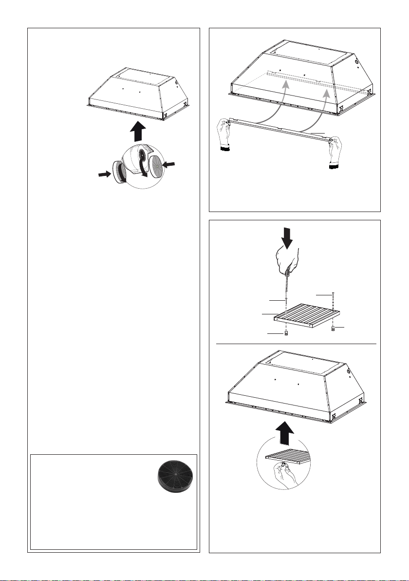
33
5
6
Fixez les
ltres à
charbon à la
grille noire
de chaque
côté du
ventilateur.
Pressez
fermement
le ltre à
charbon
contre la
grille noire
de chaque
Pour option non canalisée avec
recirculation d'air
Filtre à charbon actif accessoire
requis - n° d'article - FILTER1
(acheté séparément).
Pour réduire le risque d’incendie
ou de choc électrique, lorsque l’appareil
est utilisé en mode recirculation, utiliser
uniquement le modèle FILTER 1 pour trousse
de conversion.
côté du ventilateur et faites tourner le ltre
dans le sens des aiguilles d'une montre (vers
l'avant de la hotte encastrable) jusqu'à ce qu'il
soit verrouillé en place. Faites tourner dans le
sens contraire des aiguilles d'une montre (vers
l'arrière de la hotte encastrable) pour l'enlever.
Remplacement du ltre à charbon actif
Les ltres à charbon actif ne sont pas lavables
et ne peuvent être régénérés. Ils devraient être
remplacés environ tous les 4 mois d'utilisation,
ou plus souvent en cas d'utilisation intensive.
Enlevez le ltre à charbon en le faisant tourner
dans le sens des aiguilles d'une montre (vers
l'arrière) jusqu'à ce qu'il se dégage du carter du
moteur, puis en le tirant vers le côté.
Pour réinsérer les ltres, placez-les sur le côté
du ventilateur et poussez-les vers l'intérieur.
Tournez ensuite le ltre à charbon dans le sens
des aiguilles d'une montre (vers l'avant) jusqu'à
ce qu'il soit bien installé.
7
Filtre à chicane
Avant de poser les ltres (6), serrez les 2 boutons
(7) à l’aide de 2 vis (9e).
Utilisez les deux mains pour insérer et retirer
les ltres.
1
2
8
Engagez la gouttière (8) à l’intérieur de la
hotte. Il est possible de le laver et de le
replacer à l’intérieur de la hotte.
9e
7
6
9e
7
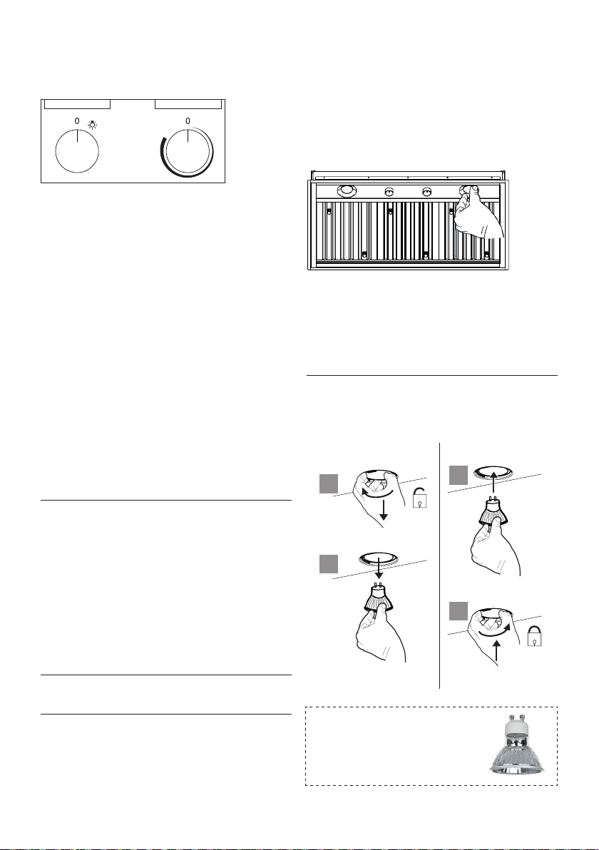
34
Panneau de commande de Rangehood
Le panneau de commande est plac au centre du
fond de capot.
Bouton "Marche/Arrêt" léger (A)
Interrupteur Marche/Arrêt pour l'éclairage. La po-
sition « 0 » éteint l’éclairage, tandis que l’éclairage
est mis en marche si l’interrupteur est tourné vers
la droite.
Bouton "Marche/Arrêt" de ventilateur (B)
Commutateur "Marche/Arrêt" pour le ventilateur.
Déplacez le cadran vers la droite d'allumer le
ventilateur et de varier la vitesse du ventilateur.
Tournez-vous vers la gauche au " ; 0" ; pour
l'arrêter.
Pour le meilleur résultat
Commencez le rangehood plusieurs minutes avant
la cuisson pour développer le ux d'air approprié.
Permettez à l'unité de fonctionner pendant
plusieurs minutes après cuisson est complet pour
dégager toutes les fumée et odeurs de la cuisine.
Nettoyage
Les ltres de graisse d'acier inoxydable et le rail de
graisse devraient être nettoyés fréquemment dans
la solution détersive chaude ou être lavés dans le
lave-vaisselle. Nettoyez les surfaces extérieures
avec un décapant disponible dans le commerce
d'acier inoxydable. Les abrasifs et les agents
de récurage peuvent rayer des nitions d'acier
inoxydable et ne devraient pas être employés pour
nettoyer les surfaces de nition.
Graissez l'installation de ltre de rail et de
graisse/déplacement
Éliminez le plastique du ltre, les boutons
doivent être installés sur le ltre avec 2 vis sur
chaque ltre.
Version 07/11 - Page 11
Light On/Off Button (A)
On/Off switch for the halogen lights. Position "0" turns the lights off,
turning the switch to the right one click is the dimmer position, and
the next click to the right is full power
Blower On/Off Button (B)
On/Off switch for the blower. Move the dial to the right to turn the
blower ON and vary the speed of the blower. Turn to the left at "0"
to turn it OFF.
For Best Result
Start the rangehood several minutes before cooking to develop proper
airflow. Allow the unit to operate for several minutes after cooking is
complete to clear all smoke and odors from the kitchen.
Cleaning
The stainless steel grease filters and grease rail should be cleaned
frequently in hot detergent solution or washed in the dishwasher.
Clean exterior surfaces with a commercially available stainless steel
cleaner. Abrasives and scouring agents can scratch stainless steel
finishes and should not be used to clean finished surfaces.
Grease rail and Grease Filter Installation / Removal
Remove the plastic from the filter, the knobs need to be installed
onto the filter with 2 screws to each filter
Install the grease rail into the back of the hood, into the slots on the
inside floor of the rear of the hood. The Grease filters should be
installed before operating the rangehood. To install the filters, use the
two knobs (in FIGURE 28) to hold the filter and insert the filter into
the front edge of the hood with the knobs facing out into the spring
loaded slot. Install the other end of the filter above the grease rail in
the back of the hood.
USE AND CARE INFORMATION
This rangehood system is designed to remove smoke, cooking vapors
and odors from the cooktop area.
Rangehood Control Panel
The control panel is located in the center of the hood bottom. The
position and function of each control button are indicated in FIGURE
27
FIGURE 28
Replacing the Halogen Lamp
Before you begin, make sure that the rangehood is turned off and
that the other lamps have had sufficient time to cool. Halogen lamps
burn extremely hot and serious injury could result from touching a hot
lamp. Press and twist the lamp to remove. Then remove the lamp
and replace with a new lamp.
WIRING DIAGRAM
This rangehood uses 45 watt PAR16
Halogen Lamps.
FIGURE 27
FIGURE 26
ALL INSTALLATIONS
1. Use a drill to install side rails on the inside rangehood walls to
line the inside hood wall with stainless, 2 and 3 in FIGURE 26 with
9a. screws, 4 screws total.
BLK
WHT
R11B41
LIGHT CONTROL
OFF / HALF LIGHT / ON
1
Y-G
A
RED
WIRING BOX
WHT
BLK
BLK
23
B
ORG
WHT
4
VLT
N
L
Y-G
LINE IN
120Vac
60Hz ~
Y-G
BLU
123
654
789
123
654
987
RED
M8 4V
120V ~
WHT
BRW
BLU
BLK
ORG
BLU
BLK
Y-G
Y-G
ON/OFF MOTOR
SPEED CONTROL
BLKBLK
BLU
123
654
789
123
654
987
RED
M8 4V
120V ~
BLU
Y-G
WHT
BRW
BLKBLK
BLU
123
654
123
654
BLK
ORG
Y-G
BLU
WHT
BLK
Y-G
WIRING BOX FOR
REMOTE BLOWER
WHT
REMOTE
BLOWER
123
654
WHT
Y-G
BLKBLK
Y-G
9a
9a
2
3
9a
9a
Lampes DEL à ballast intégré
de type Gu10 – répondant à la
norme UL 1993/nmx-j-578/1-
ance/csa c22.2 No 1993
Système d'éclairage
• Remplacez l'ampoule avec une nouvelle du même
type, en vous assurant d'insérer correctement les
deux connecteurs dans leur logement sur le socle.
a
b
a
b
Installez le rail de graisse sur le dos du capot, sur
les fentes sur le plancher intérieur de l'arrière du
capot. Les ltres de graisse devraient être installé
avant d'actionner le rangehood. Pour installer les
ltres, employez les deux boutons pour tenir le
ltre et pour insérer le ltre dans le bord avant du
capot avec les boutons faisant face dehors dans la
fente à ressort. Installez l'autre extrémité du ltre
au-dessus du rail de graisse dans le dos du capot.
A B
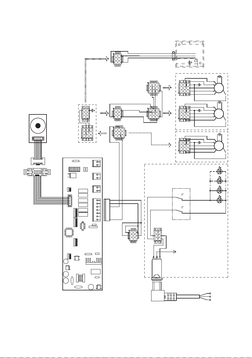
35
Schéma de câblage

36
4 janvier 2016
GARANTIE LIMITÉE ET SERVICE FABER
Tous les produits Faber font l'objet d'une garantie contre les défauts de matériel et de main-
d'œuvre,accordée à l'acheteur original pour une période d'un (1) an à compter de la date d'achat initiale
(preuve d'achat requise). Cette garantie couvre les frais de main-d'œuvre et les pièces de rechange. À sa
discrétion, Faber peut réparer ou remplacer le produit ou les composants nécessaires à remettre le produit
en bon état de marche. Pour bénéficier de services prévus par la garantie, veuillez communiquer avec le
détaillant auprès duquel vous avez acheté la hotte de cuisine, ou encore avec le distributeur Faber de votre
région. Si vous n'êtes pas en mesure de localiser un distributeur Faber dans votre région, veuillez
communiquer avec nous au 508-358-5353 pour connaître le nom d'un distributeur à proximité.
Les éléments suivants ne sont pas visés par la garantie Faber :
1. Les appels au service de réparation visant à corriger l'installation de la hotte de cuisine, à recevoir des
instructions sur l'utilisation de la hotte de cuisine, le remplacement ou la réparation des fusibles du domicile
ou la correction des câblages ou de la plomberie du domicile.
2. Les appels au service de réparation visant à réparer ou remplacer les ampoules électriques de hotte, les
fusibles ou les filtres. Ces pièces consommables ne sont pas couvertes par la garantie.
3. Les réparations si votre hotte de cuisine est employée à des fins autres que celles prévues, soit l'utilisation
résidentielle normale pour une famille.
4. Les dommages découlant d'un accident, d'une modification, de l'utilisation incorrecte ou abusive, d'un
incendie, d'une inondation, d'un cas de force majeure, d'une installation inadéquate, d'une installation non
conforme aux codes en matière d'électricité ou de plomberie ou à la documentation fournie par Faber, ou
encore d'une utilisation du produit non approuvée par Faber.
5. Les frais de main-d'œuvre ou de remplacement des pièces pour les appareils utilisés à l'extérieur des
États-Unis ou du Canada, y compris toutes les hottes de cuisine Faber non-UL ou C-UL homologuées.
6. Les réparations à la hotte découlant de modifications non autorisées apportées à la hotte de cuisine.
7. Les frais encourus pour les déplacements et le transport de produits en région éloignée et les frais de
cueillette et livraison. La réparation des hottes de cuisine Faber doit être réalisée à domicile.
LA PRÉSENTE GARANTIE NE PRÉVOIT AUCUNE FORME DE DÉDOMMAGEMENT EN CAS DE DOMMAGES ACCESSOIRES OU
CONSÉCUTIFS, Y COMPRIS, SANS TOUTEFOIS S'Y LIMITER, LES DOMMAGES DIRECTS, INDIRECTS, ACCESSOIRES,
PARTICULIERS OU CONSÉCUTIFS, LES LÉSIONS CORPORELLES/MORTELLES OU LA PERTE DE PROFITS. LA GARANTIE
OFFERTE PAR FABER EST LIMITÉE AUX CONDITIONS ÉNONCÉES CI-DESSUS ET À LA PÉRIODE DE GARANTIE INDIQUÉE
DANS LES PRÉSENTES ET EST EXCLUSIVE. SAUF DISPOSITIONS EXPRESSES CONTRAIRES DANS LE PRÉSENT ACCORD,
FABER DÉCLINE TOUTE CONDITION, REPRÉSENTATION OU GARANTIE EXPLICITE OU IMPLICITE, Y COMPRIS, SANS
TOUTEFOIS S'Y LIMITER, TOUTE GARANTIE IMPLICITE DE QUALITÉ MARCHANDE OU D'ADAPTATION À UN USAGE
PARTICULIER
.
Les droits qui vous sont conférés en vertu de la présente garantie peuvent varier d'une province ou d'un État
à l'autre.
N
o
de modèle : ______________________________ N
o
de série : _____________________________


991.0463.718_09 - 190711
D00003712_08