Loading ...
Loading ...
Loading ...
E6
Heading30" Flush Mount Installation Instructions
Parts include:
Qty. Part
DMR30M977WM/S
1
PREF-B020MRP0
Flush Mount Deector Vent
Stainless Steel
2
LX-CZB055MRE0
Mounting screws
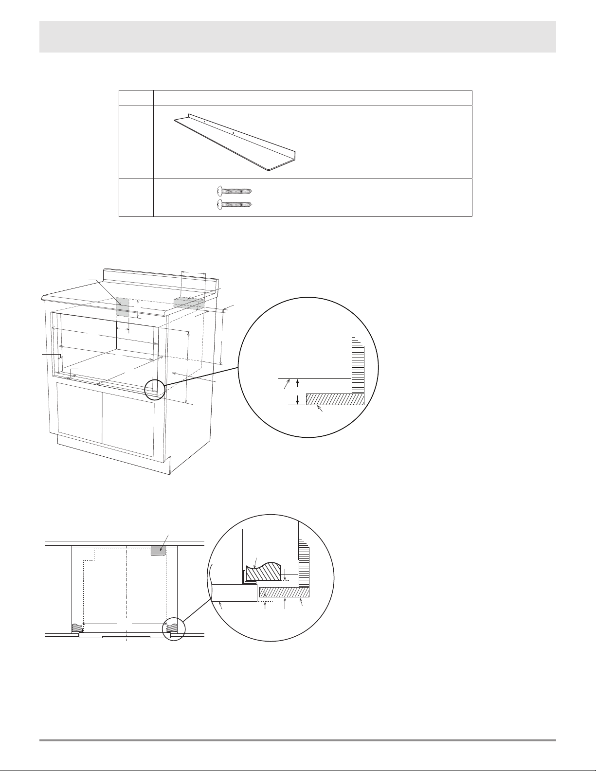
1.
Prepare cabinet opening as shown in Figures 1, 2A, 2B, 2C.
Figure 1
Figure 2A
A. 6" (152.40 mm)
B. Suggested electrical outlet location
C. Anti-Tip block
D. 5" (127 mm)
E. 3
1
/2" (88.90 mm)
F. 4" (101.60 mm)
G. 30
5
/16" (769.92 mm) minimum
30
5
/8" (777.87 mm) maximum
H. 14
13
/16" (376.24 mm) to
bottom of Anti-Tip block
I. 1
1
/16" (26.97 mm)
J. 23
1
/2" (596.90 mm) minimum depth
K. 28
7
/16" (722.3 mm)
L. 1
3
/4" (44.45 mm)
M. 16
7
/8" (428.62 mm) opening
N. Floor must support 100 lb (45.4 kg)
O. 1
3
/4" (44.45 mm)
C
L
Top view
A
Anti-Tip block
Mounting cleat
B
C
Drawer face
Cabinet
face
Note: the mounting surface of the finished cleat must sit 1
1
/16" (26.97 mm)
back
from the face of the cabinet [pushing the face of the drawer out
1
/
4
" (6.35 mm)].
A. 28
1
/2" (723.9 mm)
mounting cleat opening width
B.
1
/4" (6.35 mm)
C. 1
1
/16" (26.97 mm)
C
N
H
E
F
D
B
A
J
L
I
cabinet face
shelf face
O
G
K
M
Note: the face of the shelf must
sit 1
3
/4" (44.45 mm) back from
the face of the cabinet.
Loading ...
Loading ...
Loading ...