
ROOM
AIR
CONDITIONER
OWNER'S
MANUAL
MANUEL
D'UTILISATION
CLIMATISEUR
DE
FENETRE
AIRE
ACONDICIONADOR
MANUAL
DEL
PROPIETARIO
Please
read
the
operating
instructions
and
safety
precautions
carefully
and
thoroughly
before
installing
and
operating
your
room
air
conditioner.
MODEL,
MODELE,
MODELO:
HBLG1200H
Veuillez
lire
attentivement
et
en
entier
ce
guide
d'utilisation
et
les
mesures
de
securite
ci-incluses
avant
de
proceder
a
l'installation
et
au
fonctionnement
de
votre
climatiseur.
Por
favor
lea
las
instrucciones
de
operacion
y
las
precauciones
de
seguridad
cuidadosa
y
totalmente
antes
de
instalar
y
operar
su
acondicionador
de
aire
de
ventana.
Manufactured
by
LG
Electronics

-2-
TABLE
OF
CONTENTS
FEATURES
........................................................................................................................................2
SAFETY
PRECAUTIONS
.............................................................................................................
.....3
OPERATING
...............................................................................................................................
.......5
FUNCTION
...................................................................................................................................5
VENTILATION...............................................................................................................................6
TO
CONTROL
AIR
DIRECTION...................................................................................................6
HOW
TO
SECURE
THE
DRAIN
PIPE..........................................................................................6
AIR
FILTER
CLEANING
...............................................................................................................7
HOW
TO
USE
THE
REVERSIBLE
INLET
GRILLE
......................................................................7
ELECTRICAL
DATA
...........................................................................................................................8
BEFORE
CALLING
FOR
SERVICE
..................................................................................................8
INSTALLATION
INSTRUCTIONS
......................................................................................................9
ELECTRICAL
SAFETY.....................................................................................................................13
FEATURES
1
23
4
5
6
7
89
10
11
1213
14
15
1.
CABINET
2.
HORIZONTAL
AIR
DEFLECTOR
(VERTICAL
LOUVER)
3.
VERTICAL
AIR
DEFLECTOR
(HORIZONTAL
LOUVER)
4.
AIR
DISCHARGE
5.
FRONT
GRILLE
6.
AIR
INTAKE
(INLET
GRILLE)
17.
AIR
FILTER
18.
CONTROL
BOARD
19.
POWER
CORD
10.
EVAPORATOR
11.
CONDENSER
12.
COMPRESSOR
13.
BASE
PAN
14.
BRACE
15.
ELECTRIC
HEATER

-3-
Safety
Precautions
WARNING
To
prevent
injury
to
the
user
or
other
people
and
property
damage,
the
following
instructions
must
be
fol-
lowed.
Incorrect
operation
due
to
ignoring
of
instruction
will
cause
harm
or
damage.
The
seriousness
is
classified
by
the
following
indications.
WARNING
:
This
symbol
indicates
the
possibility
of
death
or
serious
injury.
CAUTION
:
This
symbol
indicates
the
possibility
of
injury
or
damage
to
prop-
erties
only.
Meanings
of
symbols
used
in
this
manual
are
as
shown
below.
Be
sure
not
to
do.
Be
sure
to
follow
the
instruction.
Plug
in
the
power
plug
prop-
erly.
?
Otherwise,
it
will
cause
electric
shock
or
fire
due
to
heat
genera-
tion.
Do
not
operate
or
stop
the
unit
by
inserting
or
pulling
out
the
power
plug.
?
It
will
cause
electric
shock
or
fire
due
to
heat
generation.
Do
not
damage
or
use
an
unspecified
power
cord.
?
It
will
cause
electric
shock
or
fire.
?
If
the
power
cord
is
damaged,
it
must
be
replaced
by
the
manufacturer
or
an
authorized
service
center
or
a
similarly
qualified
person
in
order
to
avoid
a
hazard.
Do
not
modify
power
cord
length
or
share
the
outlet
with
other
appliances.
?
It
will
cause
electric
shock
or
fire
due
to
heat
generation.
Do
not
operate
with
wet
hand
or
in
damp
environ-
ment.
?
It
will
cause
electric
shock.
Do
not
direct
airflow
at
room
occupants
only.
?
This
could
damage
your
health.

-4-
Sharp
edges
When
the
air
filter
is
to
be
removed,
do
not
touch
the
metal
parts
of
the
unit.
?
It
may
cause
an
injury.
Do
not
clean
the
air
conditioner
with
water.
?
Water
may
enter
the
unit
and
degrade
the
insula-
tion.
It
may
cause
an
electric
shock.
Ventilate
well
when
used
together
with
a
stove,
etc.
?
An
oxygen
shortage
may
occur.
When
the
unit
is
to
be
cleaned,
switch
the
unit
off,
and
unplug
it.
?
Since
the
fan
rotates
at
high
speed
during
oper-
ation,
it
may
cause
an
injury.
Do
not
put
a
pet
or
house
plant
where
it
will
be
exposed
to
direct
air
flow.
?
This
could
injure
the
pets
or
plants.
Do
not
use
for
special
pur-
poses.
?
Do
not
use
this
air
conditioner
to
preserve
precision
devices,
food,
pets,
plants,
and
art
objects.
It
may
cause
deterioration
of
qual-
ity,
etc.
Do
not
operate
switches
with
wet
hands.
?
It
may
cause
an
electric
shock.
Do
not
apply
an
insecticide
or
flammable
spray.
?
It
may
cause
a
fire
or
deformation
of
the
cabinet.
Do
not
put
a
heater,
etc.
where
it
is
exposed
to
direct
air
flow.
?
It
may
cause
imperfect
combus-
tion.
SHARP
EDGES!
The
edges
of
the
case
can
be
SHARP!
?
Use
caution
when
handling
the
case.
Grip
it
firmly
and
do
not
allow
it
to
slip
while
holding
it.
?
Use
heavy
gloves
to
handle
the
case
if
necessary.
?DONOT
allow
the
case
to
slide
against
your
skin!
-5-
OPERATING
?
WARNING
To
reduce
the
risk
of
fire,
electric
shock,
or
injury
to
persons,
read
the
IMPORTANT
SAFETY
INSTRUCTIONS
before
operating
this
appliance.
?
CAUTION
When
the
air
conditioner
has
been
performing
its
cooling
operation
and
is
turned
off
or
set
to
the
fan
position,
wait
at
least
3 minutes
before
resetting
to
the
cooling
operation
again.
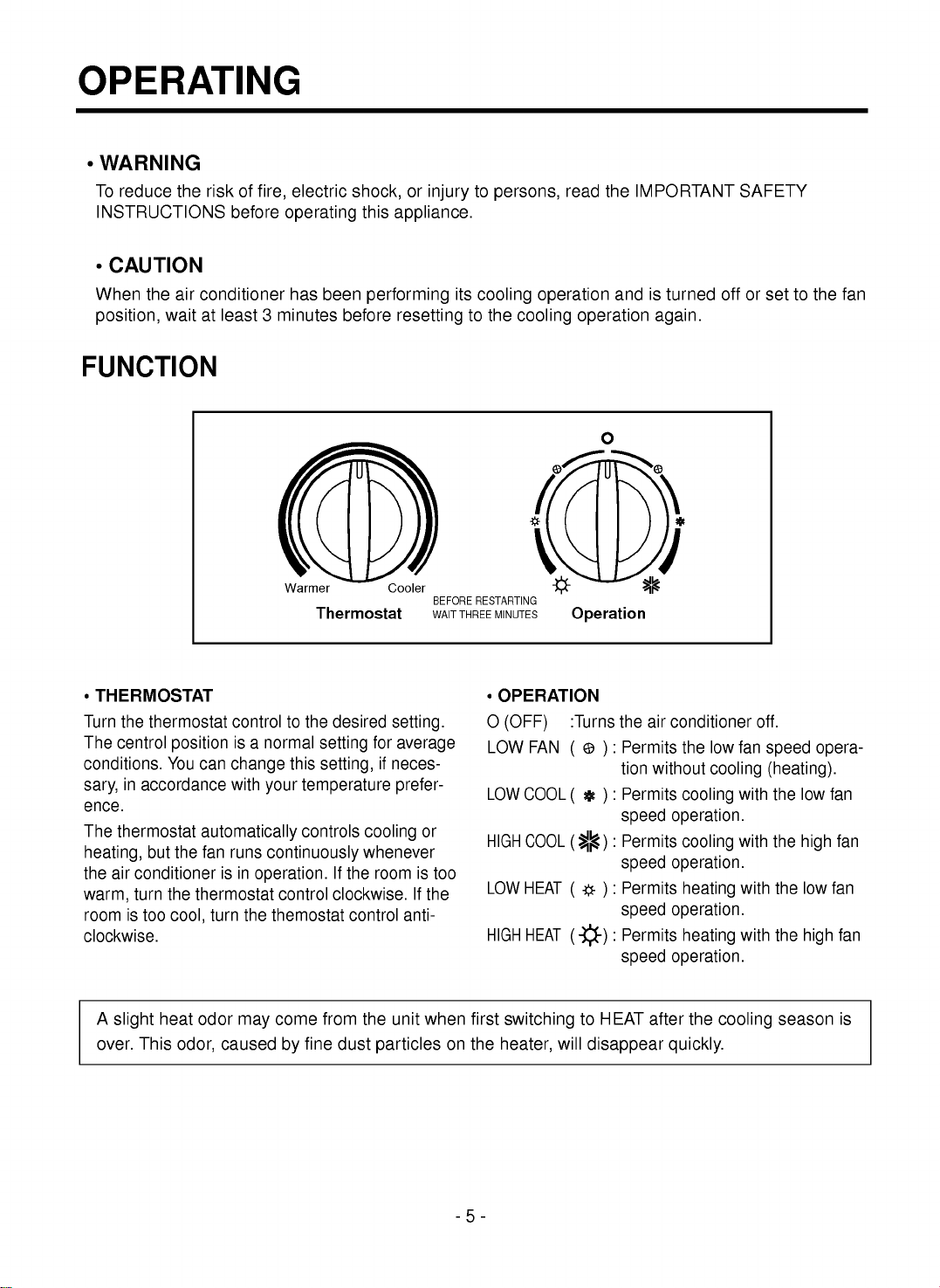
FUNCTION
Thermostat
Warmer
Cooler
BEFORE
RESTARTING
WAIT
THREE
MINUTES
Operation
A
slight
heat
odor
may
come
from
the
unit
when
first
switching
to
HEAT
after
the
cooling
season
is
over.
This
odor,
caused
by
fine
dust
particles
on
the
heater,
will
disappear
quickly.
?
THERMOSTAT
Turn
the
thermostat
control
to
the
desired
setting.
The
centrol
position
is
a
normal
setting
for
average
conditions.
You
can
change
this
setting,
if
neces-
sary,
in
accordance
with
your
temperature
prefer-
ence.
The
thermostat
automatically
controls
cooling
or
heating,
but
the
fan
runs
continuously
whenever
the
air
conditioner
is
in
operation.
If
the
room
is
too
warm,
turn
the
thermostat
control
clockwise.
If
the
room
is
too
cool,
turn
the
themostat
control
anti-
clockwise.
?
OPERATION
O
(OFF)
:Turns
the
air
conditioner
off.
LOW
FAN
( )
:
Permits
the
low
fan
speed
opera-
tion
without
cooling
(heating).
LOW
COOL
( )
:
Permits
cooling
with
the
low
fan
speed
operation.
HIGH
COOL
( )
:
Permits
cooling
with
the
high
fan
speed
operation.
LOW
HEAT
( )
:
Permits
heating
with
the
low
fan
speed
operation.
HIGH
HEAT
( )
:
Permits
heating
with
the
high
fan
speed
operation.

-6-
VENTILATION
The
ventilation
lever
must
be
CLOSE
position
in
order
to
maintain
the
best
cooling
conditions.
When
fresh
air
is
necessary
in
the
room,
set
the
ventilation
lever
to
the
OPEN
position.
The
damper
is
opened
and
room
air
is
exhausted.
TO
CONTROL
AIR
DIRECTION
The
direction
of
air
can
be
controlled
wherever
you
want
to
cool
by
adjusting
the
horizontal
louver
and
the
vertical
louver.
Part
A
Part
B
VENT
CLOSE
OPEN
NOTE:
Before
using
the
ventilation
feature,
make
a
ventilation
kit.
First,
pull
down
part
to
horizontal
line
with
part
.
?
HORIZONTAL
AIR-DIRECTION
CONTROL
The
horizontal
air
direction
is
adjusted
by
rotating
the
vertical
louver
right
or
left.
?
VERTICAL
AIR-DIRECTION
CONTROL
The
vertical
air
direction
is
adjusted
by
rotating
the
horizontal
louver
forward
or
backward.
HOW
TO
SECURE
THE
DRAIN
PIPE
Drain
pipe
Drain
cap
In
humid
weather,
excess
water
may
cause
the
BASE
PAN
to
overflow.
To
drain
the
water,
remove
the
DRAIN
CAP
and
secure
the
DRAIN
PIPE
to
the
rear
hole
of
the
BASE
PAN.
-7-
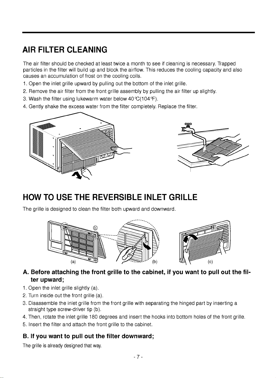
AIR
FILTER
CLEANING
The
air
filter
should
be
checked
at
least
twice
a
month
to
see
if
cleaning
is
necessary.
Trapped
particles
in
the
filter
will
build
up
and
block
the
airflow.
This
reduces
the
cooling
capacity
and
also
causes
an
accumulation
of
frost
on
the
cooling
coils.
1.
Open
the
inlet
grille
upward
by
pulling
out
the
bottom
of
the
inlet
grille.
2.
Remove
the
air
filter
from
the
front
grille
assembly
by
pulling
the
air
filter
up
slightly.
3.
Wash
the
filter
using
lukewarm
water
below
40°C(104°F).
4.
Gently
shake
the
excess
water
from
the
filter
completely.
Replace
the
filter.
HOW
TO USE
THE
REVERSIBLE
INLET
GRILLE
The
grille
is
designed
to
clean
the
filter
both
upward
and
downward.
A.
Before
attaching
the
front
grille
to
the
cabinet,
if
you
want
to
pull
out
the
fil-
ter
upward;
1.
Open
the
inlet
grille
slightly
(a).
2.
Turn
inside
out
the
front
grille (a).
3.
Disassemble
the
inlet
grille
from
the
front
grille
with
separating
the
hinged
part
by
inserting
a
straight
type
screw-driver
tip
(b).
4.
Then,
rotate
the
inlet
grille
180
degrees
and
insert
the
hooks
into
bottom
holes
of
the
front
grille.
5.
Insert
the
filter
and
attach
the
front
grille
to
the
cabinet.
B.
If
you
want
to
pull
out
the
filter
downward;
The
grille
is
already
designed
that
way.
(b)
b
(a)
(c)
-8-
ELECTRICAL
DATA
BEFORE
CALLING
FOR
SERVICE
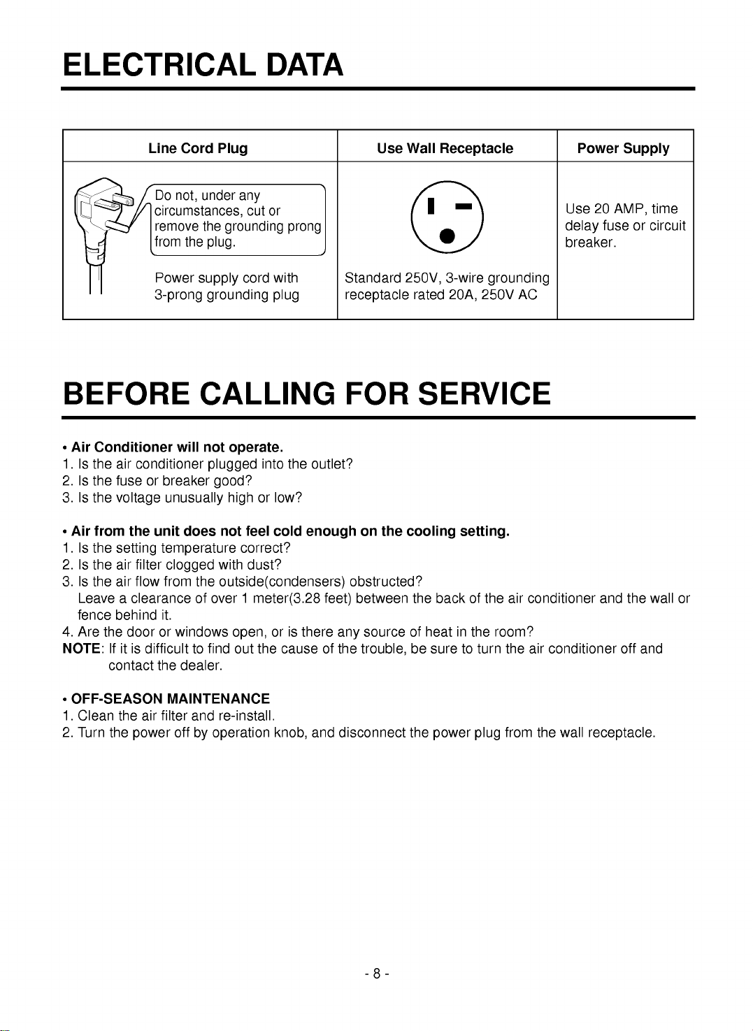
Do
not,
under
any
circumstances,
cut
or
remove
the
grounding
prong
from
the
plug.
Power
supply
cord
with
3-prong
grounding
plug
Standard
250V,
3-wire
grounding
receptacle
rated
20A,
250V
AC
Use
20
AMP,
time
delay
fuse
or
circuit
breaker.
Line
Cord
Plug
Use
Wall
Receptacle
Power
Supply
?
Air
Conditioner
will
not
operate.
1.
Is
the
air
conditioner
plugged
into
the
outlet?
2.
Is
the
fuse
or
breaker
good?
3.
Is
the
voltage
unusually
high
or
low?
?
Air
from
the
unit
does
not
feel
cold
enough
on
the
cooling
setting.
1.
Is
the
setting
temperature
correct?
2.
Is
the
air
filter
clogged
with
dust?
3.
Is
the
air
flow
from
the
outside(condensers)
obstructed?
Leave
a
clearance
of
over
1
meter(3.28
feet)
between
the
back
of
the
air
conditioner
and
the
wall
or
fence
behind
it.
4.
Are
the
door
or
windows
open,
or
is
there
any
source
of
heat
in
the
room?
NOTE:
If
it
is
difficult
to
find
out
the
cause
of
the
trouble,
be
sure
to
turn
the
air
conditioner
off
and
contact
the
dealer.
?
OFF-SEASON
MAINTENANCE
1.
Clean
the
air
filter
and
re-install.
2.
Turn
the
power
off
by
operation
knob,
and
disconnect
the
power
plug
from
the
wall
receptacle.

-9-
INSTALLATION
INSTRUCTIONS
SELECT
THE
BEST
LOCATION
1.
To
prevent
vibration
and
noise,
make
sure
the
unit
is
installed
securely
and
firmly
2.
Install
the
unit
where
the
sunlight
does
not
shine
directly
on
the
unit.
3.
The
outside
of
the
cabinet
must
extend
outward
for
at
least
12"
and
there
should
be
no
obstacles,
such
as
a
fence
or
wall,
within
20"
from
the
back
of
the
cabinet
because
it
will
prevent
heat
radiation
of
the
condenser.
Restriction
of
outside
air
will
greatly
reduce
the
cooling
efficiency
of
the
air
conditioner.
CAUTION:
All
side
louvers
of
the
cabinet
must
remain
exposed
to
the
outside
of
the
structure.
WINDOW
REQUIREMENTS
1.
This
unit
is
designed
for
installation
in
standard
double
hung
windows
with
actual
opening
widths
from
27"
to
39".
The
top
and
bottom
window
sash
must
open
sufficiently
to
allow
a
clear
vertical
opening
of
16"
from
the
bottom
of
the
upper
sash
to
the
window
stool.
2.
Install
the
unit
a
little
slanted
so
the
back
is
slightly
lower than
the
front(about
1/2").
This
will
force
condensed
water
to
flow
to
the
outside.
3.
Install
the
unit
with
the
bottom
about
30"~60"
above
the
floor
level.
About
1/2"
30"~60"
Awning
Cooled
air
Fence
Over
20"
Heat
radiation
Interior
wall
Stool
16"
min
27"
to
39"
1/2"
to
11/4"
Offset
Sill
Exterior
235/8"
min
(Without
frame
curtain)
1
2 3 4
89
11
765
10
13
12
NO.
NAME
OF
PARTS
Q'TY
1
FRAME
CURTAIN
2
2
SILL
SUPPORT
2
3
BOLT
2
4
NUT
2
5
SCREW(TYPE
A)
16
6
SCREW(TYPE
B)
3
7
SCREW(TYPE
C)
5
8
FOAM-STRIP
1
9
FOAM-PE
1
10
UPPER
GUIDE
1
11
FOAM-PE
1
12
FRAME
GUIDE
2
13
WINDOW
LOCKING
BRACKET
1
INSTALLATION
KITS
CONTENTS

9
10
11
10
5
5
5
12
12
Shipping
screws
EPS
Material
(Type
A)
(Type
A)
Upper
Guide
Window
Sash
Window
stool
Front
Angle
Upper
guide
10
Foam-pe
9
Frame
Curtain
1
Foam-pe
11
Cabinet
-10-
SUGGESTED
TOOL
REQUIREMENTS
SCREWDRIVER(+,
-),
RULLER,
KNIFE,
HAMMER,
PENCIL,
LEVEL
PREPARATION
OF
CHASSIS
1.
Remove
the
screws
which
fasten the
cabinet
at
both
sides
and
at
the
back.
2.
Slide
the
unit
from
the
cabinet
by
gripping
the
base
pan
handle
and
pulling
forward
while
bracing
the
cabinet.
3.
Remove
EPS
Material.
4.
Cut
the
window
sash
seal
to
the
proper
length.
Peel
off
the
backing
and
attach
the
foam-pe
to
the
underside
of
the
window
sash.
5.
Remove
the
backing
from
the
top
upper
guide
Foam
PE
and
attach
it
to
the
bottom
of
the
upper
guide
6.
Attach
the
upper
guide
onto
the
top
of
the
cabinet
with
3
type
A
screws.
7.
Insert
the
frame
guides
into
the
bottom
of
the
cabinet.
8.
Insert
the
Frame
Curtain
into
the
upper
guide
and
frame
guides
.
9.
Fasten
the curtains
to
the
unit
with
4
Type
A
screws.
CABINET
INSTALLATION
1.
Open
the
window.
Mark
a
line
on
center
of
the
window
stool(or
desired
air
conditioner
location).
Carefully
place
the
cabinet
on
the
window
stool
and
align
the
center
mark
on
the
bottom
front
with
the
center
line
marked
in
the
window
stool.
2.
Pull
the
bottom
window
sash
down
behind
the
upper
guide
until
it
meets.
NOTE:
?
Do
not
pull
the
window
sash
down
so
tightly
that
the
movement
of
Frame
Curtain
is
restricted.
Fig.
1
Fig.
2

-11-
3.
Loosely
assemble
the
sill
support
using
the
parts
in
Fig.
3.
4.
Select
the
position
that
will
place
the
sill
support
near
the
outer
most
point
on
sill
(See
Fig.
4)
NOTE:
Be
careful
when
you
install
the
cabinet
(frame
guides
are
broken
so
easily).
5.
Attach
the
sill
support
to
the
cabinet
track
hole
in
relation
to
the
selected
position
using
2
Type
A
screws
in
each
support(See
Fig.
4).
6.
The
cabinet
should
be
installed
with
a
very
slight
tilt(about
1/2")
downward
toward
the
outside
(See
Fig.
5).
Adjust
the
bolt
and
the
nut
of
sill
support
for
balancing
the
cabinet.
7.
Attach
the
cabinet
to
the
window
stool
by
driving
the
screws
(Type
B:
Length
sixteen
millimeters
and
below.)
through
the
front
angle
into
window
stool.
8.
Pull
each
Frame
curtain
fully
to
each
window
sash
track,
and
repeat
step
2.
9.
Attach
each
Frame
curtain
the
window
sash
using
screws
(Type
C).
(See
Fig. 6)
INDOOR
OUTDOOR
INDOOR
OUTDOOR
Sash
track
Front
Angle
Cabinet
About 1/2"
About 1/2"
Sill
Support
2
Nut
4
Bolt
3
Frame
Guide
12
Screw(Type
B)
6
Screw(Type
B)
6
Sill
support
2
Sill
support
2
TypeC7
Screw(Type
A)
5
Fig.
3
Fig.
4
Fig.
5
Fig.
6

-12-
10.
Slide
the
unit
into
the
cabinet.(See
Fig. 7)
CAUTION:
For
security
purpose,
reinstall
screws(Type
A)
at
cabinet's
sides.
11.
Cut
the
foam-strip
to
the
proper
length
and
insert
between
the
upper
window
sash
and
the
lower
window
sash.
(See
Fig. 8)
12.
Attach
the
window
locking
bracket
with
a
type
C
screw.
(See
Fig. 9)
13.
Attach
the
front
grille
to
the
cabinet
by
insert-
ing
the
tabs
on
the
grille
into
the
tabs
on
the
front
of
the
cabinet.
Push
the
grille
in
until
it
snaps
into
place.(See
Fig.10)
14.
Lift
the
inlet
grille
and
secure
it
with
a
type
A
screw
through
the
front
grille.(See
Fig.
11)
Screw(Type
A)
Screw(Type
A)
Power
cord
Foam-Strip
8
Window
locking
bracket
13
Fig.
7
Fig.
8
Fig.
9
Fig.
12
Fig.
10
Fig.
11
-13-
ELECTRICAL
SAFETY
ELECTRICAL
SAFETY
IMPORTANT
GROUNDING
INSTRUCTIONS
Air
conditioner
has
a
three-prong
grounding
plug
on
its
power
supply
cord,
which
must
be
plugged
into
prop-
erly
grounded
three-prong
wall
receptacle
for
your
pro-
tection
against
possible
shock
hazard.
FUSE
--
Use
a
time-delay
fuse
or
circuit
breaker.
Refer
to
serial
plate
for
proper
power
supply
requirements.
230, 208,
and
230/208
VOLT
UNITS
These
units
are
equipped
with
a
three-prong
ground-
ing
plug
on
the
power
supply
cord,
which
must
be
plugged
into
a
matching
properly
grounded
three-
prong
wall
receptacle
for
your
protection
against
possi-
ble
shock
hazard.
If
such
an
outlet
is
not
present,
one
must
be
installed
by
a
qualified
electrician
in
accor-
dance
with
the
National
Electrical
Code
and
local
codes
and
ordinances.
NOTE:
DO
NOT
USE
AN
EXTENSION
CORD
ON
230,
208,
AND
230/208
VOLT
UNITS.


