Loading ...
Loading ...
Loading ...
8
Preparing for Installation
WARNING
If the home utilities do not meet product specifications, postpone
installation. Call the dealer, the gas supplier, or a licensed electrician.
IMPORTANT: Within the Commonwealth of Massachusetts, this range
must be installed by a licensed plumber or gas fitter.
Verifying the Parts List
Verify that everything on the Parts List is present. If anything is missing/
damaged, contact the dealer immediately. Do not install a damaged/
incomplete range.
Parts List
• 2 grates
• 3 standard porcelain burner caps
• 3 standard burner rings
• 1 SimmerSear burner porcelain burner cap
• 1 SimmerSear burner ring
• 1 GlideRack™ oven rack
• 1 standard rack
• 5 burner-control knobs (4 cooktop, 1 oven)
• 1 anti-tip bracket with screws, anchors
• 1 bottle stainless-steel cleaner
• Literature kit
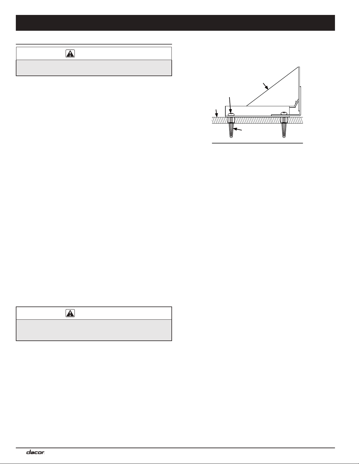
Installing the Anti-Tip Bracket
Install the anti-tip bracket before installing the range. Mount the bracket
to the floor (preferred) or the wall (only if floor mounting is unsuitable).
If the range’s front panel (excluding bull nose) is over 27” (68.6 cm) from
the back wall, or if the flooring is too thick (see Wall-Mounting the Anti-
Tip Bracket), wall-mounting is unsuitable.
Floor-Mounting the Anti-Tip Bracket
Provided are four plastic anchors and three sizes (4 each) of #8 or #12
Phillips-head screws for mounting the bracket. The anchors are for
concrete sub-flooring only.
WARNING
To work properly, the anti-tip bracket must be mounted as instructed
to the sub-floor (including cement board). Do not attach the bracket
directly to tile, linoleum, or other flooring.
1. Establish the range center line and front-panel locations via Product
Dimensions (Pg. 5) and the cabinet/cutout dimensions.
2.
a pencil, mark the 4 mounting holes on the floor.
3. Determine screw size.
The minimum full thread depth (portion of screw threaded into
SCREW-SIZE TABLE
Mounting the Bracket To a Concrete Floor
1.
the concrete slab below.
2. With a 3/16” bit, drill 4 anchor holes 1-¼” (3.2 cm) into the slab.
This depth is longer than the anchor but needed for proper installation.
3. Clean out the holes, and tap in the anchors so the tops are flush with
the concrete slab.
4. Place the bracket holes over the anchor holes, then insert the 4 screws
(ensuring their threads engage the anchors), and tighten the screws.
Mounting the Bracket To a Wood Floor
1. Drill four countersink holes through the floor covering to expose the
wood below.
2.
holes in the wood floor.
3. Position the anti-tip bracket holes over the holes, then insert and
tighten the 4 screws.
Installation Instructions
Sub-floor
Screws attached
to sub-floor below
floor covering
Anti-tip
bracket
Floor
covering
Concrete anchors
(concrete
sub-floor only)
Loading ...
Loading ...
Loading ...