*9001018793*
'+/&$8
/%$8
Ú ,QVWDOODWLRQLQVWUXFWLRQV
[
[
ʦ
$
%
D
PLQ
PLQ
E
F
D E
F
G
H

D
E
F G
D E
en
Ú
,QVWDOODWLRQLQVWUXFWLRQV
: ,PSRUWDQWVDIHW\LQIRUPDWLRQ
5HDGWKHVHLQVWUXFWLRQVFDUHIXOO\2QO\WKHQZLOO\RXEHDEOHWR
RSHUDWH\RXUDSSOLDQFHVDIHO\DQGFRUUHFWO\5HWDLQWKHLQVWUXFWLRQ
PDQXDODQGLQVWDOODWLRQLQVWUXFWLRQVIRUIXWXUHXVHRUIRU
VXEVHTXHQWRZQHUV
&KHFN WKH DSSOLDQFH IRU GDPDJH DIWHU XQSDFNLQJ LW 'R QRW FRQQHFW
WKHDSSOLDQFHLILWKDVEHHQGDPDJHGLQWUDQVSRUW
7KHDSSOLDQFHFDQRQO\EHXVHGVDIHO\LILWLVFRUUHFWO\LQVWDOOHG
DFFRUGLQJ WR WKH VDIHW\ LQVWUXFWLRQV 7KH LQVWDOOHU LV UHVSRQVLEOH IRU
HQVXULQJWKDWWKHDSSOLDQFHZRUNVSHUIHFWO\DWLWVLQVWDOODWLRQ
ORFDWLRQ
7KHZLGWKRIWKHH[WUDFWRUKRRGPXVWFRUUHVSRQGDWOHDVWZLWKWKH
ZLGWKRIWKHKRE
)RU WKH LQVWDOODWLRQ REVHUYH WKH FXUUHQWO\ YDOLG EXLOGLQJ UHJXODWLRQV
DQGWKHUHJXODWLRQVRIWKHORFDOHOHFWULFLW\DQGJDVVXSSOLHUV
:KHQ FRQYH\LQJ WKH H[KDXVW DLU RIILFLDO DQG OHJDO UHJXODWLRQV HJ
VWDWHEXLOGLQJUHJXODWLRQVPXVWEHIROORZHG
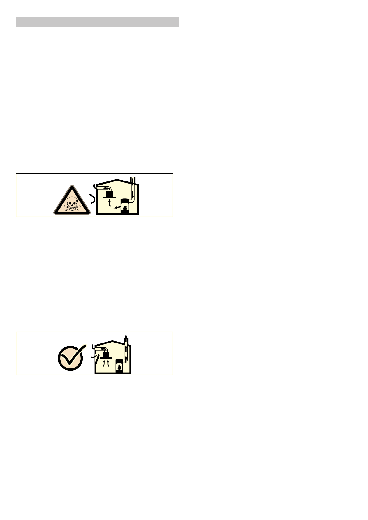
'DQJHURIGHDWK
5LVNRISRLVRQLQJIURPIOXHJDVHVWKDWDUHGUDZQEDFNLQ
$OZD\VHQVXUHDGHTXDWHIUHVKDLULQWKHURRPLIWKHDSSOLDQFHLV
EHLQJRSHUDWHGLQH[KDXVWDLUPRGHDWWKHVDPHWLPHDVURRPDLU
GHSHQGHQWKHDWSURGXFLQJDSSOLDQFHLVEHLQJRSHUDWHG
5RRPDLUGHSHQGHQWKHDWSURGXFLQJDSSOLDQFHVHJJDVRLO
ZRRGRUFRDORSHUDWHGKHDWHUVFRQWLQXRXVIORZKHDWHUVRUZDWHU
KHDWHUVREWDLQFRPEXVWLRQDLUIURPWKHURRPLQZKLFKWKH\DUH
LQVWDOOHGDQGGLVFKDUJHWKHH[KDXVWJDVHVLQWRWKHRSHQDLU
WKURXJKDQH[KDXVWJDVV\VWHPHJDFKLPQH\
,Q FRPELQDWLRQ ZLWK DQ DFWLYDWHG YDSRXU H[WUDFWRU KRRG URRP DLU LV
H[WUDFWHGIURPWKHNLWFKHQDQGQHLJKERXULQJURRPVDSDUWLDO
YDFXXPLVSURGXFHGLIQRWHQRXJKIUHVKDLULVVXSSOLHG7R[LF
JDVHVIURPWKHFKLPQH\RUWKHH[WUDFWLRQVKDIWDUHVXFNHGEDFN
LQWRWKHOLYLQJVSDFH
■ $GHTXDWHLQFRPLQJDLUPXVWWKHUHIRUHDOZD\VEHHQVXUHG
■ $QLQFRPLQJH[KDXVWDLUZDOOER[DORQHZLOOQRWHQVXUH
FRPSOLDQFHZLWKWKHOLPLW
6DIHRSHUDWLRQLVSRVVLEOHRQO\ZKHQWKHSDUWLDOYDFXXPLQWKH
SODFHZKHUHWKHKHDWSURGXFLQJDSSOLDQFHLVLQVWDOOHGGRHVQRW
H[FHHG3DPEDU7KLVFDQEHDFKLHYHGZKHQWKHDLU
QHHGHGIRUFRPEXVWLRQLVDEOHWRHQWHUWKURXJKRSHQLQJVWKDW
FDQQRWEHVHDOHGIRUH[DPSOHLQGRRUVZLQGRZVLQFRPLQJ
H[KDXVWDLUZDOOER[HVRUE\RWKHUWHFKQLFDOPHDQV
,Q DQ\ FDVH FRQVXOW \RXU UHVSRQVLEOH 0DVWHU &KLPQH\ 6ZHHS +H
LVDEOHWRDVVHVVWKHKRXVHVHQWLUHYHQWLODWLRQVHWXSDQGZLOO
VXJJHVWWKHVXLWDEOHYHQWLODWLRQPHDVXUHVWR\RX
8QUHVWULFWHGRSHUDWLRQLVSRVVLEOHLIWKHYDSRXUH[WUDFWRUKRRGLV
RSHUDWHGH[FOXVLYHO\LQWKHFLUFXODWLQJDLUPRGH
5LVNRIGHDWK
5LVNRISRLVRQLQJIURPIOXHJDVHVWKDWDUHGUDZQEDFNLQ7KH
H[KDXVWDLUPXVWQRWEHFRQYH\HGLQWRDIXQFWLRQLQJVPRNHRU
H[KDXVWJDVIOXHRULQWRDVKDIWZKLFKLVXVHGWRYHQWLODWH
LQVWDOODWLRQURRPVWKDWFRQWDLQKHDWLQJDSSOLDQFHV,IWKHH[KDXVW
DLU LV WR EH FRQYH\HG LQWR D QRQIXQFWLRQLQJ VPRNH RU H[KDXVW JDV
IOXH\RXPXVWREWDLQWKHFRQVHQWRIWKHKHDWLQJHQJLQHHU
UHVSRQVLEOH
'DQJHURIVXIIRFDWLRQ
3DFNDJLQJPDWHULDOLVGDQJHURXVWRFKLOGUHQ1HYHUDOORZFKLOGUHQ
WRSOD\ZLWKSDFNDJLQJPDWHULDO
5LVNRIHOHFWULFVKRFN
■ &RPSRQHQWV LQVLGH WKH DSSOLDQFH PD\ KDYH VKDUS HGJHV 7KHVH
PD\GDPDJHWKHFRQQHFWLQJFDEOH'RQRWNLQNRUSLQFKWKH
FRQQHFWLQJFDEOHGXULQJLQVWDOODWLRQ
5LVNRIHOHFWULFVKRFN
■ ,WPXVWDOZD\VEHSRVVLEOHWRGLVFRQQHFWWKHDSSOLDQFHIURPWKH
HOHFWULFLW\VXSSO\7KHDSSOLDQFHPXVWRQO\EHFRQQHFWHGWRD
SURWHFWLYH FRQWDFW VRFNHW WKDW KDV EHHQ FRUUHFWO\ LQVWDOOHG ,I WKH
SOXJLVQRORQJHUDFFHVVLEOHRQFHWKHDSSOLDQFHKDVEHHQ
LQVWDOOHGRUDIL[HGFRQQHFWLRQLVUHTXLUHGWKHLQVWDOODWLRQPXVW
KDYHDQDOOSROHLVRODWLQJVZLWFKZLWKDFRQWDFWJDSRIDWOHDVW
PP2QO\DQHOHFWULFLDQPD\LQVWDOOWKHIL[HGFRQQHFWLRQ:H
UHFRPPHQGLQVWDOOLQJDUHVLGXDOFXUUHQWFLUFXLWEUHDNHU5&&%
LQWKHDSSOLDQFHVSRZHUVXSSO\FLUFXLW
5LVNRIILUH
■ *UHDVH GHSRVLWV LQ WKH JUHDVH ILOWHU PD\ FDWFK ILUH 7KH VSHFLILHG
VDIHW\GLVWDQFHVPXVWEHREVHUYHGLQRUGHUWRSUHYHQWDQ
DFFXPXODWLRQRIKHDW2EVHUYHWKHVSHFLILFDWLRQVIRU\RXU
FRRNLQJDSSOLDQFH,IJDVEXUQHUVDQGHOHFWULFKRWSODWHVDUH
RSHUDWHGWRJHWKHUWKHODUJHVWVSHFLILHGGLVWDQFHDSSOLHV
5LVNRIILUH
■ *UHDVHGHSRVLWVLQWKHJUHDVHILOWHUPD\FDWFKILUH1HYHUZRUN
ZLWKQDNHGIODPHVFORVHWRWKHDSSOLDQFHHJIODPEpLQJ'R
QRWLQVWDOOWKHDSSOLDQFHQHDUDKHDWSURGXFLQJDSSOLDQFHIRU
VROLGIXHOHJZRRGRUFRDOXQOHVVDFORVHGQRQUHPRYDEOH
FRYHULVDYDLODEOH7KHUHPXVWEHQRIO\LQJVSDUNV
5LVNRILQMXU\
■ &RPSRQHQWV LQVLGH WKH DSSOLDQFH PD\ KDYH VKDUS HGJHV :HDU
SURWHFWLYHJORYHV
5LVNRILQMXU\
■ 7KH DSSOLDQFH PD\ IDOO GRZQ LI LW KDV QRW EHHQ SURSHUO\ IDVWHQHG
LQSODFH$OOIDVWHQLQJFRPSRQHQWVPXVWEHIL[HGILUPO\DQG
VHFXUHO\
5LVNRILQMXU\
■ 7KHDSSOLDQFHLVKHDY\7RPRYHWKHDSSOLDQFH SHRSOHDUH
UHTXLUHG8VHRQO\VXLWDEOHWRROVDQGHTXLSPHQW
5LVNRILQMXU\
■ &KDQJHVWRWKHHOHFWULFDORUPHFKDQLFDODVVHPEO\DUH
GDQJHURXVDQGPD\OHDGWRPDOIXQFWLRQV'RQRWPDNHDQ\
FKDQJHVWRWKHHOHFWULFDORUPHFKDQLFDODVVHPEO\

*HQHUDOLQIRUPDWLRQ
([KDXVWGXFW
1RWH 7KHDSSOLDQFHPDQXIDFWXUHUGRHVQRWSURYLGHDQ\ZDUUDQW\
IRUIDXOWVDWWULEXWDEOHWRWKHSLSHVHFWLRQ
■ 7KH DSSOLDQFH DFKLHYHV LWV RSWLPXP SHUIRUPDQFH E\ PHDQV RI D
VKRUWVWUDLJKWH[KDXVWDLUSLSHDQGDVODUJHDSLSHGLDPHWHUDV
SRVVLEOH
■ $V D UHVXOW RI ORQJ URXJK H[KDXVW DLU SLSHV PDQ\ SLSH EHQGV RU
SLSHGLDPHWHUVWKDWDUHVPDOOHUWKDQPPWKHRSWLPXP
H[WUDFWLRQSHUIRUPDQFHLVQRWDFKLHYHGDQGIDQQRLVHLV
LQFUHDVHG
■ 7KH SLSHV RU KRVHV IRU OD\LQJ WKH H[KDXVW DLU OLQH PXVW FRQVLVW RI
QRQFRPEXVWLEOHPDWHULDO
■ ,I WKH H[KDXVW DLU LV FRQYH\HG WKURXJK WKH RXWHU ZDOO D WHOHVFRSLF
ZDOOER[VKRXOGEHXVHG
5LVNRIGDPDJHIURPUHWXUQLQJFRQGHQVDWH,QVWDOOWKHH[KDXVW
GXFW LQ VXFK D ZD\ WKDW LW IDOOV DZD\ IURP WKH DSSOLDQFH VOLJKWO\
VORSH
5RXQGSLSHV
$QLQQHUGLDPHWHURIPPEXWDWOHDVWPPLV
UHFRPPHQGHG
)ODWGXFWV
7KHLQQHUFURVVVHFWLRQPXVWFRUUHVSRQGWRWKHGLDPHWHURIWKH
URXQGSLSHV
GLDPPFDFP
GLDPPFDFP
■ )ODWGXFWVVKRXOGKDYHQRVKDUSGHIOHFWLRQV
■ 8VHVHDOLQJVWULSIRUGHYLDWLQJSLSHGLDPHWHUV
(OHFWULFDOFRQQHFWLRQ
: 5LVNRIHOHFWULFVKRFN
&RPSRQHQWVLQVLGHWKHDSSOLDQFHPD\KDYHVKDUSHGJHV7KHVH
PD\GDPDJHWKHFRQQHFWLQJFDEOH'RQRWNLQNRUSLQFKWKH
FRQQHFWLQJFDEOHGXULQJLQVWDOODWLRQ
7KHUHTXLUHGFRQQHFWLRQLQIRUPDWLRQLVRQWKHDSSOLDQFHV
LGHQWLILFDWLRQSODWH
7KLVDSSOLDQFHFRPSOLHVZLWKWKH(&LQWHUIHUHQFHVXSSUHVVLRQ
UHJXODWLRQV
7KLVDSSOLDQFHPXVWRQO\EHFRQQHFWHGWRDFRUUHFWO\LQVWDOOHG
HDUWKHGVRFNHW
$WWDFKWKHHDUWKHGVRFNHWSUHIHUDEO\LQVLGHWKHIOXHGXFW
■ 7KHHDUWKHGVRFNHWVKRXOGEHFRQQHFWHGYLDLWVRZQFLUFXLW
■ ,IWKHHDUWKHGVRFNHWLVQRORQJHUDFFHVVLEOHDIWHULQVWDOOLQJWKH
DSSOLDQFH DQ DOOSROH LVRODWLQJ VZLWFK HJ FLUFXLW EUHDNHU IXVHV
DQGFRQWDFWRUVZLWKDWOHDVWDPPFRQWDFWJDSPXVWEH
LQFOXGHGLQWKHLQVWDOODWLRQ
,QVWDOODWLRQSUHSDUDWLRQ
&KHFNLQJWKHILWWHGXQLW
■ 7KHILWWHGXQLWPXVWEHOHYHODQGKDYHVXIILFLHQWORDGEHDULQJ
FDSDFLW\
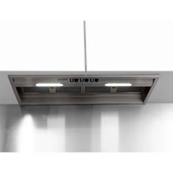
■ 7KHPD[LPXPZHLJKWRIWKHH[WUDFWRUKRRGLV NJ
$SSOLDQFHGLPHQVLRQVDQGVDIHW\FOHDUDQFHV
■ 2EVHUYHWKHDSSOLDQFHVGLPHQVLRQV )LJ $
■ &RPSO\ZLWKWKHVDIHW\FOHDUDQFHV )LJ %
,I WKH LQVWDOODWLRQ LQVWUXFWLRQV IRU WKH JDV FRRNLQJ DSSOLDQFH VSHFLI\
D GLIIHUHQW GLVWDQFH WKH ODUJHU RI WKH WZR PXVW DOZD\V EH SURYLGHG
IRU
3UHSDULQJWKHXQLWV
7KHILWWHGXQLWPXVWEHKHDWUHVLVWDQWXSWR&7KHILWWHGXQLW
PXVWVWLOOEHVWXUG\DIWHUWKHFXWRXWVKDYHEHHQPDGH
$IWHUPDNLQJWKHFXWRXWVUHPRYHDQ\VKDYLQJV
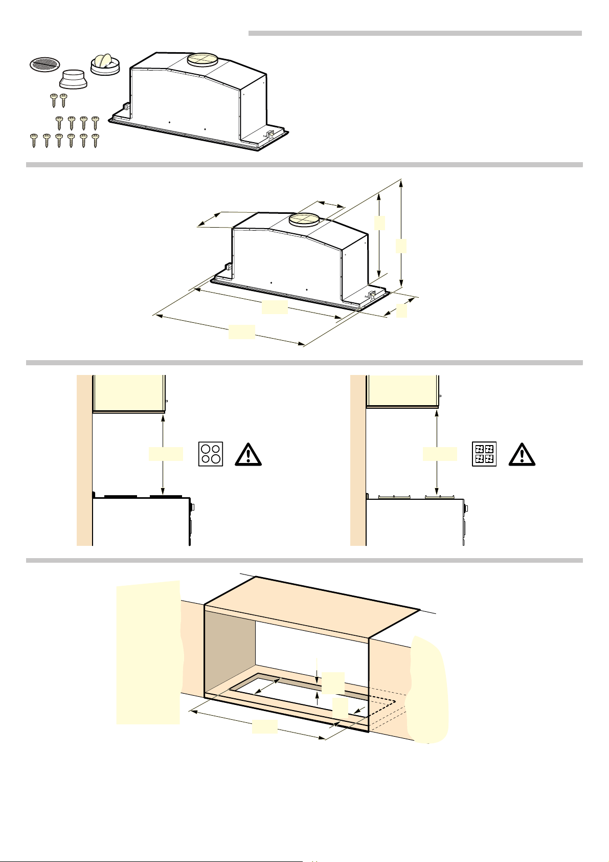
0DNHWKHFXWRXWLQWKHILWWHGXQLW )LJD
0DNHWKHFXWRXWIRUWKHH[KDXVWDLUSLSH
1RWH <RXFDQPDNHWKHH[KDXVWDLURSHQLQJHLWKHUDERYHWKH
ILWWHGXQLW )LJERUEHKLQGWKHILWWHGXQLW )LJF
3UHSDULQJWKHDSSOLDQFH
2SHQWKHILOWHUFRYHU )LJD
1RWH *UDVSWKHIURQWFRUQHUVRIWKHILOWHUFRYHUDQGSXOOLWGRZQ
LQDVLQJOHVZLIWPRWLRQ
8QGRWKHKLQJHORFNDQGUHPRYHWKHILOWHUFRYHU )LJE
5HPRYHWKHPHWDOJUHDVHILOWHUVHHWKHLQVWUXFWLRQPDQXDO
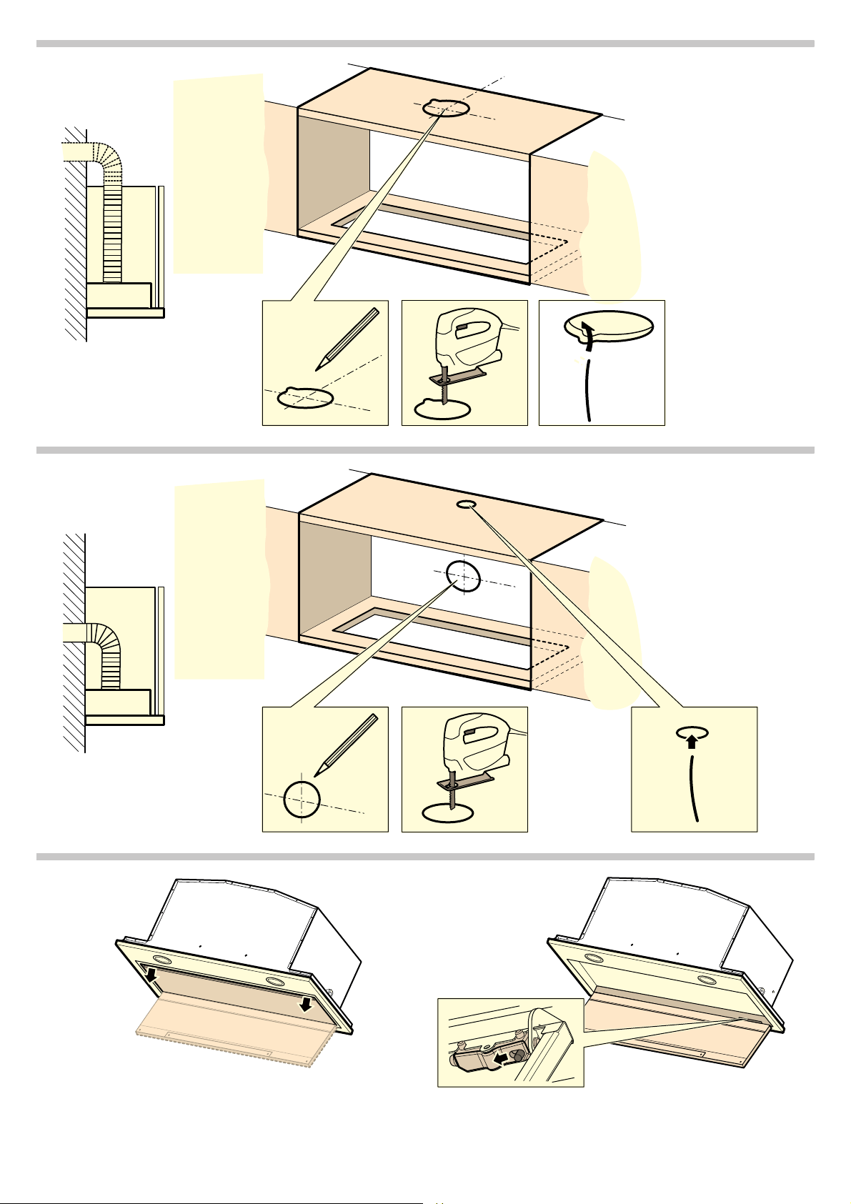
'LVFRQQHFWWKHFDEOLQJIRUWKHFRQWUROSDQHODQGWKHOLJKWLQJ
)LJF
8QGRWKHVFUHZVLQWKHIUDPHDQGUHPRYHWKHIUDPH )LJG
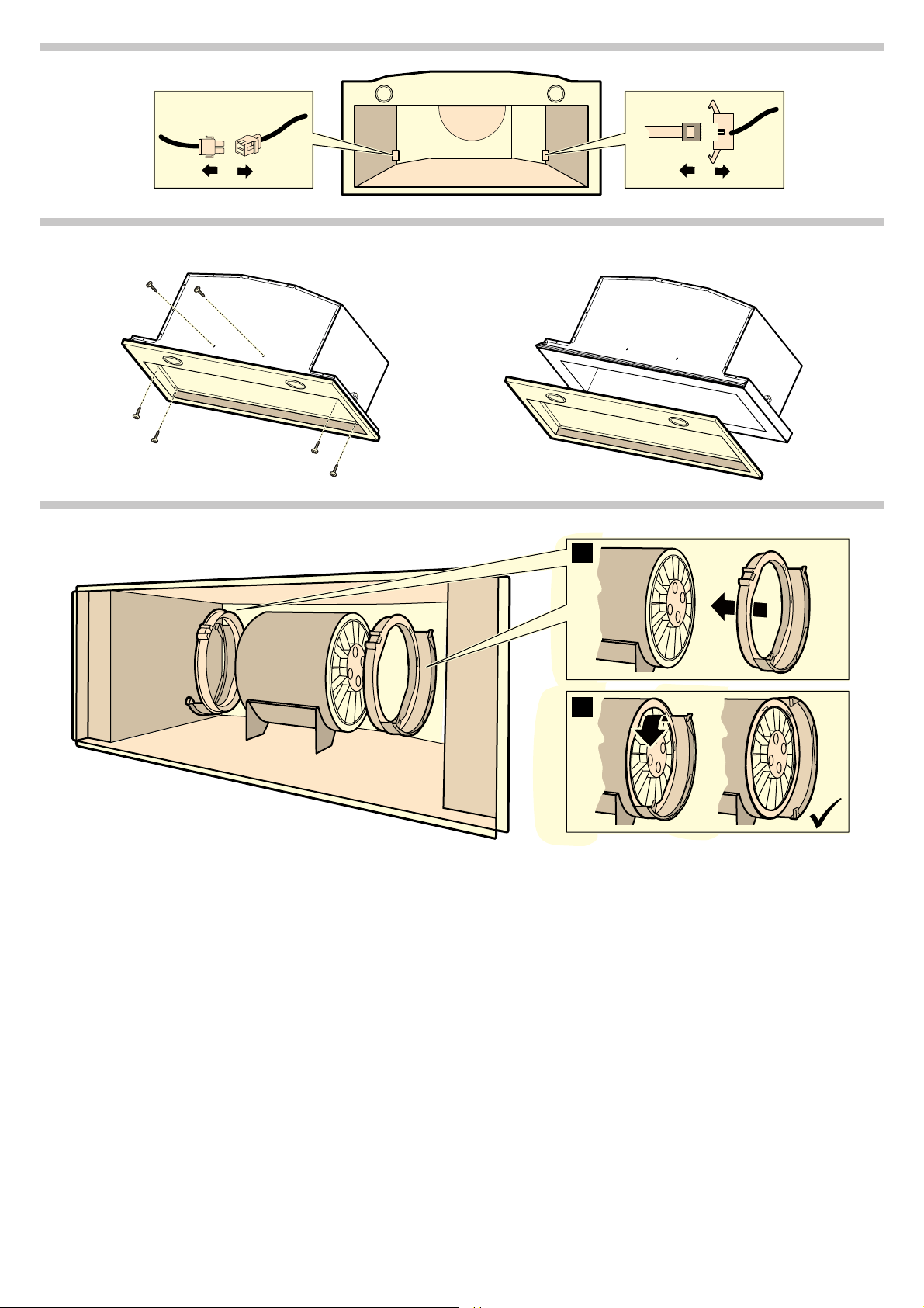
2SWLRQDOIRUDLUUHFLUFXODWLRQ
3RVLWLRQWKHILOWHUUHWDLQHURSWLRQDODFFHVVRU\FRUUHFWO\RQWKH
PRWRUDQGWXUQLWWRWKHIURQWXQWLOLWORFNVLQWRSODFH,QVHUWWKH
DFWLYDWHGFKDUFRDOILOWHULQWRWKHILOWHUUHWDLQHU )LJH
,QVWDOOLQJWKHDSSOLDQFH
3ODFHWKHDSSOLDQFHLQWRWKHRSHQLQJLQWKHILWWHGXQLWDQGVFUHZ
LWWRWKHILWWHGXQLW )LJ D
7LJKWHQWKHIDVWHQLQJVFUHZV )LJ E
'LVFRQQHFWWKHFDEOLQJIRUWKHFRQWUROSDQHODQGWKHOLJKWLQJ
3XW WKH IUDPH LQ SODFH DQG VFUHZ LW WR WKH DSSOLDQFH IURP EHORZ
)LJ F
6HFXUHWKHIUDPHDQGWKHDSSOLDQFHZLWKVFUHZV )LJ G
1RWH ,IWKHVFUHZVDUHQRWDFFHVVLEOHIURPWKHH[WHULRUWKHVH
FDQDOVREHILWWHGIURPWKHLQWHULRU
,QVHUWWKHPHWDOJUHDVHILOWHU
$WWDFKDQGFORVHWKHILOWHUFRYHU

&RQQHFWLQJWKHDSSOLDQFH
1RWHV
■ )RUH[KDXVWDLURSHUDWLRQDEDFNIORZIODSVKRXOGEHILWWHG,ID
EDFNIORZ IODS KDV QRW EHHQ LQFOXGHG ZLWK WKH DSSOLDQFH LW FDQ EH
REWDLQHGIURPDVSHFLDOLVWUHWDLOHU
■ ,I WKH H[KDXVW DLU LV FRQYH\HG WKURXJK WKH RXWHU ZDOO D WHOHVFRSLF
ZDOOER[VKRXOGEHXVHG
(VWDEOLVKLQJWKHFRQQHFWLRQIRUWKHH[KDXVWDLU)LJ D
1RWH ,IDQDOXPLQLXPSLSHLVXVHGVPRRWKWKHFRQQHFWLRQDUHD
EHIRUHKDQG
$WWDFKWKHH[KDXVWDLUSLSHGLUHFWO\WRWKHDLUSLSHFRQQHFWRU
&RQQHFWLWWRWKHH[KDXVWDLURSHQLQJ
6HDOWKHMRLQWVDSSURSULDWHO\
(VWDEOLVKLQJWKHFRQQHFWLRQIRUWKHFLUFXODWHGDLU)LJE
1RWHV
■ ,IDQDOXPLQLXPSLSHLVXVHGVPRRWKWKHFRQQHFWLRQDUHD
EHIRUHKDQG
■ )LWWKHDLUJXLGHJULOOHVRWKDWWKHDLUFDQIORZRXWIUHHO\
$WWDFKWKHH[KDXVWDLUSLSHGLUHFWO\WRWKHDLUSLSHFRQQHFWRU
(VWDEOLVKWKHFRQQHFWLRQWRWKHRSHQLQJRQWKHILWWHGXQLW
6FUHZWKHDLUJXLGHJULOOHWRWKHILWWHGXQLW
6HDOWKHMRLQWVDSSURSULDWHO\
(VWDEOLVKLQJDFRQQHFWLRQWRWKHPDLQV
3OXJWKHPDLQVSOXJLQWRWKHHDUWKHGVRFNHW
5HPRYLQJWKHDSSOLDQFH
'LVFRQQHFWWKHDSSOLDQFHIURPWKHSRZHUVXSSO\
'LVFRQQHFWWKHH[KDXVWDLUOLQHV
2SHQWKHILOWHUFRYHU
5HPRYHWKHJUHDVHILOWHU
'LVFRQQHFWWKHFDEOLQJIRUWKHFRQWUROSDQHODQGWKHOLJKWLQJ
5HPRYHWKHIUDPH
8QGRWKHIDVWHQLQJWRWKHILWWHGXQLW
5HPRYHWKHDSSOLDQFH