Loading ...
Loading ...
Loading ...
6
ASSEMBLY
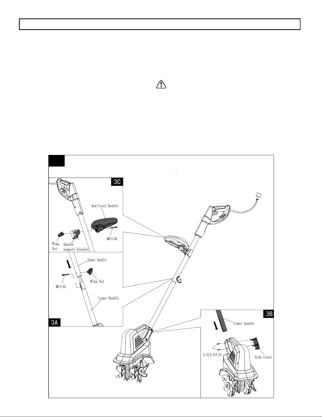
UPPER AND LOWER HANDLE SECTIONS (Fig. 3A)
Slide the lower handle section into the upper handle section.
Line up the holes on each tube, and make sure the cable is
clear of the mounting holes. Secure the two sections together
with the M6x45 carriage bolt and wing nut.
AUXILIARY HANDLE (Fig. 3C)
Position the auxiliary handle so that the holes are in alignment
with the holes in the handle support bracket. Insert the M6X50
hex head bolt into the hex shaped bolt hole of the bracket.
Secure by tightening the wing nut onto the bolt.
Loosen the wing nut and adjust the angle and height of the
handle to a safe and comfortable position. Secure into place by
tightening the wing nut onto the bolt.
3
LOWER HANDLE WITH TILLING HEAD (Fig. 3B)
Align the notch on the lower handle with the rib on the tilling
head, and push the lower handle into the tilling head. Align the
side cover with the holes on the lower handle shaft and push
the cover into place. Secure with the two ST3.9x19 Philips
head self-tapping screws.
WARNING: When connecting the tilling head and lower han-
dle using the two self-tapping screws supplied, make sure the
screws are securely tightened. Screw heads should be re-
cessed below the surface. DO NOT START THE UNIT
UNTIL TILLING HEAD AND LOWER HANDLE ARE
SECURELY CONNECTED.
Once the tilling head and lower handle are securely
connected, do not remove the self-tapping screws or attempt
to disassemble for any purpose. The self-tapping screws will
lose their effectiveness of securing the assembly if removed
and re-installed.
Loading ...
Loading ...
Loading ...