Installation
Instructions
Questions? Call 1-800-561-3344 or Visit our Website at: GEAppliances.ca
READ CAREFULLY.
KEEP THESE INSTRUCTIONS
.
Read these instructions completely and carefully.
IMPORTANT
–
Save these
instructions for local inspector’s use.
IMPORTANT
–
Observe all
governing codes and ordinances.
Note to Installer
–
Be sure to leave these
instructions with the Consumer.
BEFORE YOU BEGIN
Note to Consumer
–
Keep these instructions
for future reference.
6NLOOOHYHO – Installation of this appliance requires basic
mechanical and electrical skills.
Proper installation is the responsibility of the installer.
Product failure due to improper installation is not
covered under the Warranty.
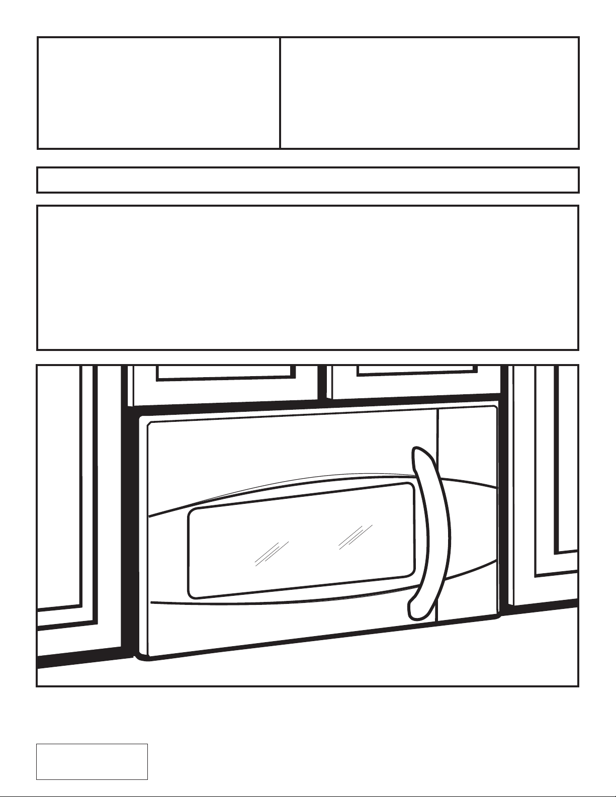
$ERYHWKH
&RRNWRS2YHQ
LA SECTION FRANÇAISE
COMMENCE À LA PAGE 25.
PVM9195 and PVM9215
350A4502P759
49-40732 (07-14)
2
Recirculating ................................................. 19–22
Attach Mounting Plate to Wall ................19
Preparation of Top Cabinet......................19
Adapting Blower
for Recirculation ..................................20, 21
Mount the Oven ...................................21, 22
Installing the Charcoal Filter ....................22
%HIRUH<RX8VH<RXU2YHQ .......................................... 23
CONTENTS
General information
Important Safety Instructions........................................ 3
Electrical Requirements .................................................. 3
Hood Exhaust ................................................................ 4, 5
Damage – Shipment/Installation .................................. 6
Parts Included ................................................................... 6
Tools You Will Need ......................................................... 7
Mounting Space ................................................................ 7
Step-by-step installation guide
Placement of Mounting Plate .................................. 8–10
Removing the Mounting Plate ............................. 8
Finding the Wall Studs .......................................... 8
Determining Wall Plate Location ........................ 9
Aligning the Wall Plate ....................................... 10
Installation Types .................................................... 11–22
Outside Top Exhaust .................................... 12–14
Attach Mounting Plate to Wall .................12
Preparation of Top Cabinet.......................13
Assemble and Install Adaptor ..................13
Mount the Oven ................................... 13, 14
Adjust the Exhaust Adaptor ......................14
Connecting Ductwork ................................14
Outside Back Exhaust .................................. 15–18
Preparing Rear Wall for
Outside Back Exhaust ................................ 15
Attach Mounting Plate to Wall .......... 15, 16
Preparation of Top Cabinet.......................16
Adapting Blower for Outside
Back Exhaust .......................................... 16, 17
Mount the Oven .......................................... 18
A
B
C
Installation Instructions

A qualified electrician must perform a ground continuity
check on the wall receptacle before beginning the
installation to ensure that the outlet box is properly
grounded. If not properly grounded, or if the wall
receptacle does not meet electrical requirements noted
(under ELECTRICAL REQUIREMENTS), a qualified electrician
should be employed to correct any deficiencies.
WARNING:
5LVNRI(OHFWULF6KRFN
Can cause injury or death:
5HPRYHKRXVHIXVHRU
RSHQFLUFXLWEUHDNHUEHIRUH
EHJLQQLQJLQVWDOODWLRQWRDYRLG
VHYHUHRUIDWDOVKRFNLQMXU\
WARNING:5LVNRI(OHFWULF6KRFN
Can cause injury or death: THIS APPLIANCE MUST BE
PROPERLY GROUNDED WRDYRLGVHYHUHRUIDWDOVKRFN
120 V Models
The power cord of this
appliance is equipped with
a three-prong (grounding)
plug which mates with
a standard three-prong
(grounding) wall receptacle
to minimize the possibility
RIHOHFWULFVKRFNKD]DUG
from this appliance.
IMPORTANT SAFETY INSTRUCTIONS
3
ELECTRICAL REQUIREMENTS
Installation Instructions
Ensure proper
ground exists
before use
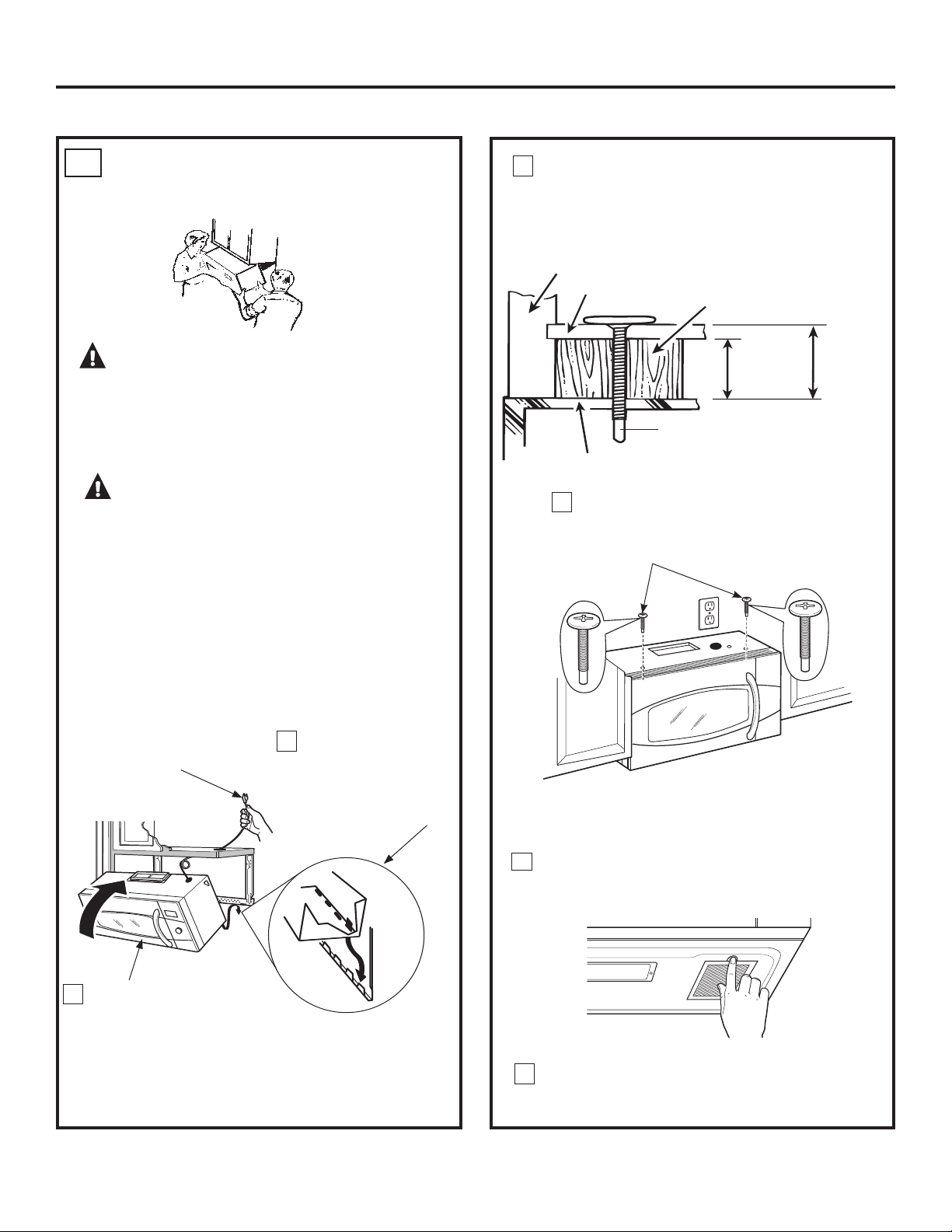
CAUTION: For personal safety, the
mounting surface must be capable of supporting the
cabinet load, in addition to the added weight of this
²SRXQGSURGXFWSOXVDGGLWLRQDORYHQORDGVRIXS
to 50 pounds or a total weight of 113–135 pounds.
CAUTION: For personal safety, this product
cannot be installed in cabinet arrangements such as an
island or a peninsula. It must be mounted to BOTH a top
cabinet AND a wall.
CAUTION:7RDYRLGWKHULVNRISHUVRQDO
LQMXU\EDFNLQMXU\RURWKHULQMXULHVGXHWRH[FHVVLYH
ZHLJKWRIWKHPLFURZDYHRUSURSHUW\GDPDJH\RXZLOO
QHHGWZRSHRSOHWRLQVWDOOWKLVPLFURZDYH
Where a standard two-prong wall receptacle is
encountered, it must be replaced with a properly
grounded three-prong wall receptacle, installed by a
qualified electrician.
WARNING:5LVNRI(OHFWULF6KRFN
Can cause injury or death: DO NOT, under any
FLUFXPVWDQFHVFXWGHIRUPRUUHPRYHDQ\RIWKHSURQJV
from the power cord. Do not use with an extension cord.
)DLOXUHWRFRPSO\PD\FDXVH¿UH
120 V Models
This product requires a three-prong grounded outlet.
Product rating is 120 volts AC, 60 Hertz, 13.5 amps,
and 1.50 kilowatts. This product must be connected
to a supply circuit of the proper voltage and frequency.
Wire size must conform to the requirements of the
National Electrical Code or the prevailing local code
for this kilowatt rating. The power supply cord and
plug should be brought to a separate 15 to 20 ampere
branch circuit single grounded outlet. The outlet box
should be located in the cabinet above the oven and
away from any potential microwave ducting.The outlet
box and supply circuit should be installed by a qualified
electrician and conform to the National Electrical Code or
the prevailing local code.
4
HOOD EXHAUST
NOTE: 5HDGWKHVHQH[WWZRSDJHVRQO\LI\RXSODQWRYHQW\RXUH[KDXVWWRWKHRXWVLGH
,I\RXSODQWRUHFLUFXODWHWKHDLUEDFNLQWRWKHURRPSURFHHGWRSDJH
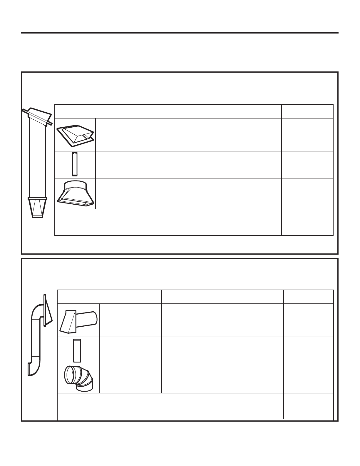
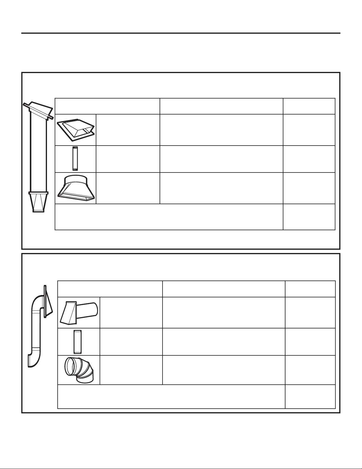
OUTSIDE TOP EXHAUST (EXAMPLE ONLY)
EQUIVALENT NUMBER EQUIVALENT
DUCT PIECES LENGTH x USED = LENGTH
Roof Cap 24 Ft. x (1) = 24 Ft.
12 Ft. Straight Duct 12 Ft. x (1) = 12 Ft.
(6s Round)
Rectangular-to-Round 5 Ft. x (1) = 5 Ft.
Transition Adaptor*
Equivalent lengths of duct pieces are based on actual tests and
reflect requirements for good venting performance with any vent hood.
Total Length = 41 Ft.
* IMPORTANT: If a rectangular-to-round transition adaptor is used, the bottom corners of the damper will
have to be cut to fit, using the tin snips, in order to allow free movement of the damper.
The following chart describes an example of one possible
ductwork installation.
Installation Instructions
The following chart describes an example of one possible
ductwork installation.
NOTE: For back exhaust, care should be taken to align exhaust with space between studs, or wall should be prepared
at the time it is constructed by leaving enough space between the wall studs to accommodate exhaust.
OUTSIDE BACK EXHAUST (EXAMPLE ONLY)
EQUIVALENT NUMBER EQUIVALENT
DUCT PIECES LENGTH* x USED = LENGTH
Wall Cap 40 Ft. x (1) = 40 Ft.
3 Ft. Straight Duct 3 Ft. x (1) = 3 Ft.
(3
1
ø4s x 10s Rectangular)
90° Elbow 10 Ft. x (2) = 20 Ft.
Equivalent lengths of duct pieces are based on actual tests and
reflect requirements for good venting performance with any vent hood.
Total Length = 63 Ft.
1” = 2.5 cm; 1’ = 0.3 m
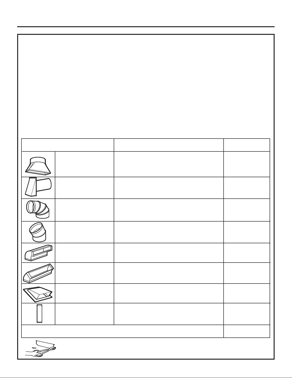
EQUIVALENT NUMBER EQUIVALENT
DUCT PIECES LENGTH x USED = LENGTH
Rectangular-to-Round 5 Ft. x ( ) = Ft.
Transition Adaptor*
Wall Cap 40 Ft. x ( ) = Ft.
90° Elbow 10 Ft. x ( ) = Ft.
45° Elbow 5 Ft. x ( ) = Ft.
90° Elbow 25 Ft. x ( ) = Ft.
45° Elbow 5 Ft. x ( ) = Ft.
Roof Cap 24 Ft. x ( ) = Ft.
Straight Duct 6s Round or 1 Ft. x ( ) = Ft.
3
1
ø4s x 10s Rectangular
7RWDO'XFWZRUN )W
Equivalent lengths of duct pieces are based on actual tests and
reflect requirements for good venting performance with any vent
hood.
* IMPORTANT: If a rectangular-to-round transition
adaptor is used, the bottom corners of the damper
will have to be cut to fit, using the tin snips, in order
to allow free movement of the damper
.
NOTE: If you need to install ducts, note that the total duct
length of 3
1
ø4s x 10s rectangular or 6s diameter round duct
VKRXOGQRWH[FHHGHTXLYDOHQWIHHW
Outside ventilation requires a HOOD EXHAUST DUCT.
Read the following carefully.
NOTE: It is important that venting be installed using
the most direct route and with as few elbows as possible.
This ensures clear venting of exhaust and helps prevent
blockages. $OVRPDNHVXUHGDPSHUVVZLQJIUHHO\DQG
QRWKLQJLVEORFNLQJWKHGXFWV
Exhaust connection:
The hood exhaust has been designed to mate with
a standard 3
1
ø4s x 10s rectangular duct.
If a round duct is required, a rectangular-to-round
transition adaptor must be used. Do not use less than
a 6s diameter duct.
Maximum duct length:
For satisfactory air movement, the total duct length of
3
1
ø4s x 10s rectangular or 6s diameter round duct should
QRWH[FHHGHTXLYDOHQWIHHW
Elbows, transitions, wall and roof caps, etc.,
present additional resistance to airflow and are equivalent
to a section of straight duct which is longer than their actual
physical size. When calculating the total duct length, add the
equivalent lengths of all transitions and adaptors plus the
length of all straight duct sections. The chart below shows
you how to calculate total equivalent ductwork length using
the approximate feet of equivalent length
of some typical ducts.
5
Installation Instructions
1” = 2.5 cm; 1’ = 0.3 m
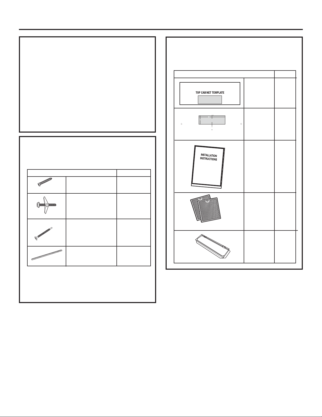
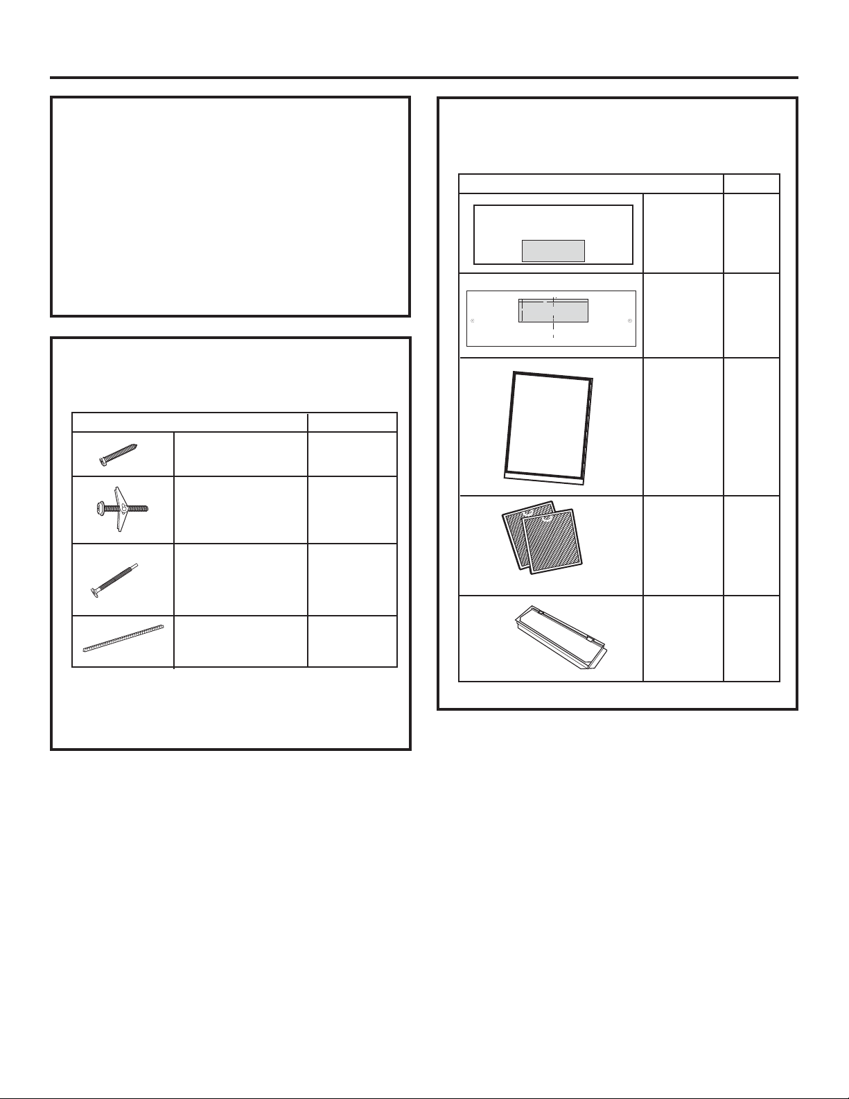
PART
QUANTITY
Top Cabinet 1
Template
Rear Wall 1
Template
Installation 1
Instructions
Separately 2
Packed
Grease
Filters
Exhaust
Adaptor with
1
Damper
6
If the unit is damaged in shipment, return
the unit to the store in which it was bought for
repair or replacement.
If the unit is damaged by the customer, repair or
replacement is the responsibility of the customer.
,IWKHXQLWLVGDPDJHGE\WKHLQVWDOOHU (if other than
the customer), repair or replacement must
be made by arrangement between customer
and installer.
DAMAGE – SHIPMENT/
INSTALLATION
PARTS INCLUDED
ADDITIONAL PARTS
Installation Instructions
PART QUANTITY
Wood Screws 2
(
1
ø4s x 2s)
Toggle Bolts (and 2
wing nuts) (
1
ø4s x 3s)
Self-aligning Machine
2
Screw (
1
ø4s-28 x 2
5
ø8s)
Nylon Grommet 1
(for metal cabinets)
PARTS INCLUDED
You will find the installation hardware contained
in a packet with the unit. Check to make sure you
have all these parts.
NOTE:
Some extra parts are included.
HARDWARE PACKET
12”
(30.5 cm )
4”
(10.2 cm )
REAR W ALL TEM PLA TE
1/ 4
”
(0.9 cm) TO EDGE
F. CUT OUT FO R HORIZO N T AL
OUTSIDE EXH AUST
1” = 2.5 cm; 1’ = 0.3 m
7
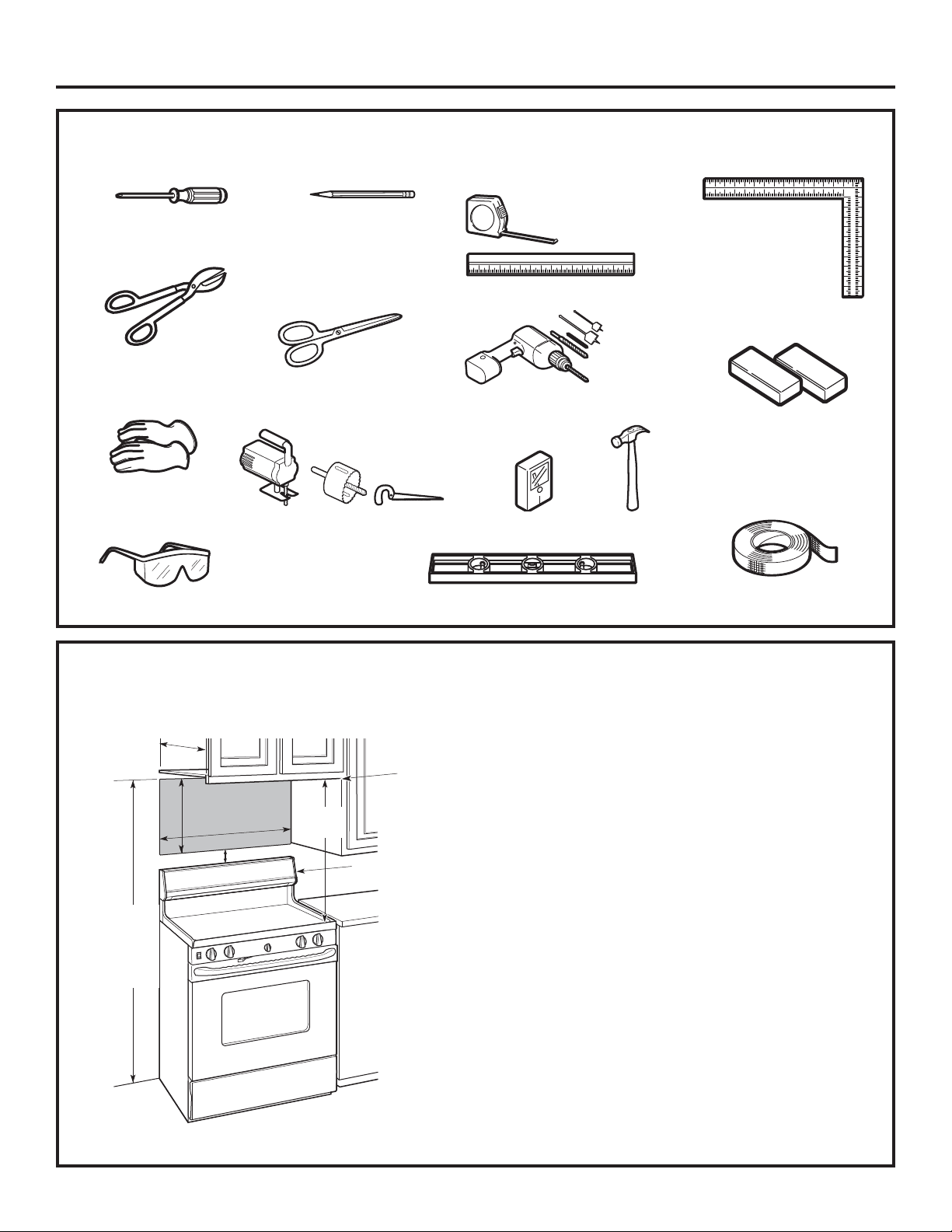
TOOLS YOU WILL NEED
# 1 and #2 Phillips
screwdriver
Pencil
Ruler or tape
measure and
straight edge
Carpenter square
(optional)
Tin snips (for cutting
damper, if required)
Electric drill with
3
ø16s,
7
ø16s,
1
ø2s and
5
ø8s drill bits
Hammer (optional)
Stud finder
or
Filler blocks or scrap
wood pieces, if needed
for top cabinet spacing
(used on recessed bottom
cabinet installations only)
Gloves
Saw (saber, hole or keyhole)
Level
Duct and masking
tape
MOUNTING SPACE
NOTES:
The space between the cabinets must be 30s wide
and free of obstructions.
If the space between the cabinets is greater than
30s, a Filler Panel Kit may be used to fill in the gap
between the oven and the cabinets. Your Owner’s
Manual contains the kit number for your model.
This oven is for installation over ranges up to
36s wide.
If you are going to vent your oven to the outside,
see Hood Exhaust Section for exhaust duct
preparation.
When installing the oven beneath smooth, flat
cabinets, be careful to follow the instructions
on the top cabinet template for power cord
clearance.
0D[LPXPFDELQHWGHSWKDERYHDQGEHVLGHWKHXQLW
is 13s.
)RUPRGHOVZLWKWRSYHQWLQJKROHV'RQRWDOORZ
cabinetry or other objects to block the airflow of the
vent.
7KHSURGXFWVKRXOGQRWEHLQVWDOOHGRYHUDQ\
cooktop or range with a combined BTU greater
than 66,000 BTU.
Backsplash
66s or
more from
the floor to
the top of
the oven
30s
2s
30s
min.
16-
1
ø4s
Bottom edge of
cabinet needs to
be 30s or more
from the cooking
surface
Installation Instructions
Scissors (to cut
template, if necessary)
Safety goggles
13smax.
1” = 2.5 cm; 1’ = 0.3 m
8
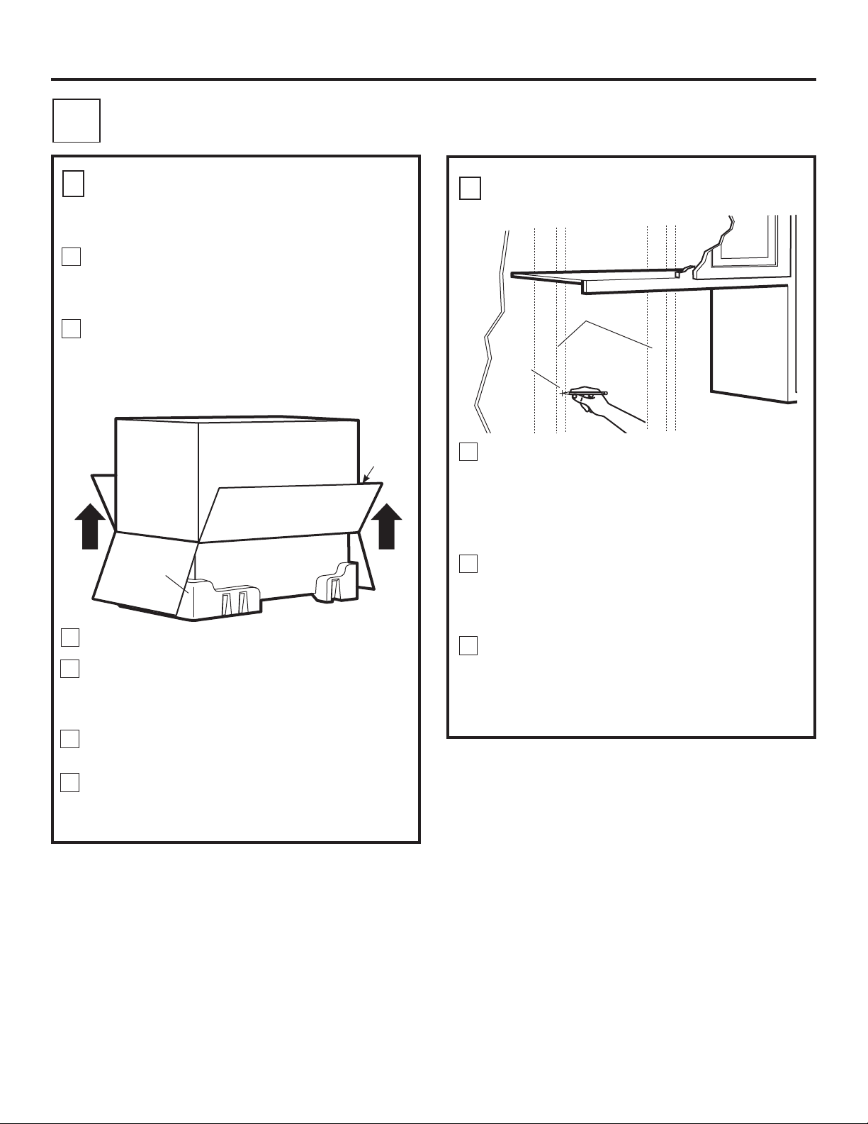
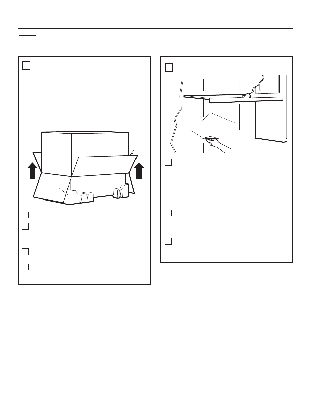
Find the studs, using one of the following methods:
A. Stud finder – a magnetic device which locates nails.
OR
B. Use a hammer to tap lightly across the mounting
surface to find a solid sound. This will indicate
a stud location.
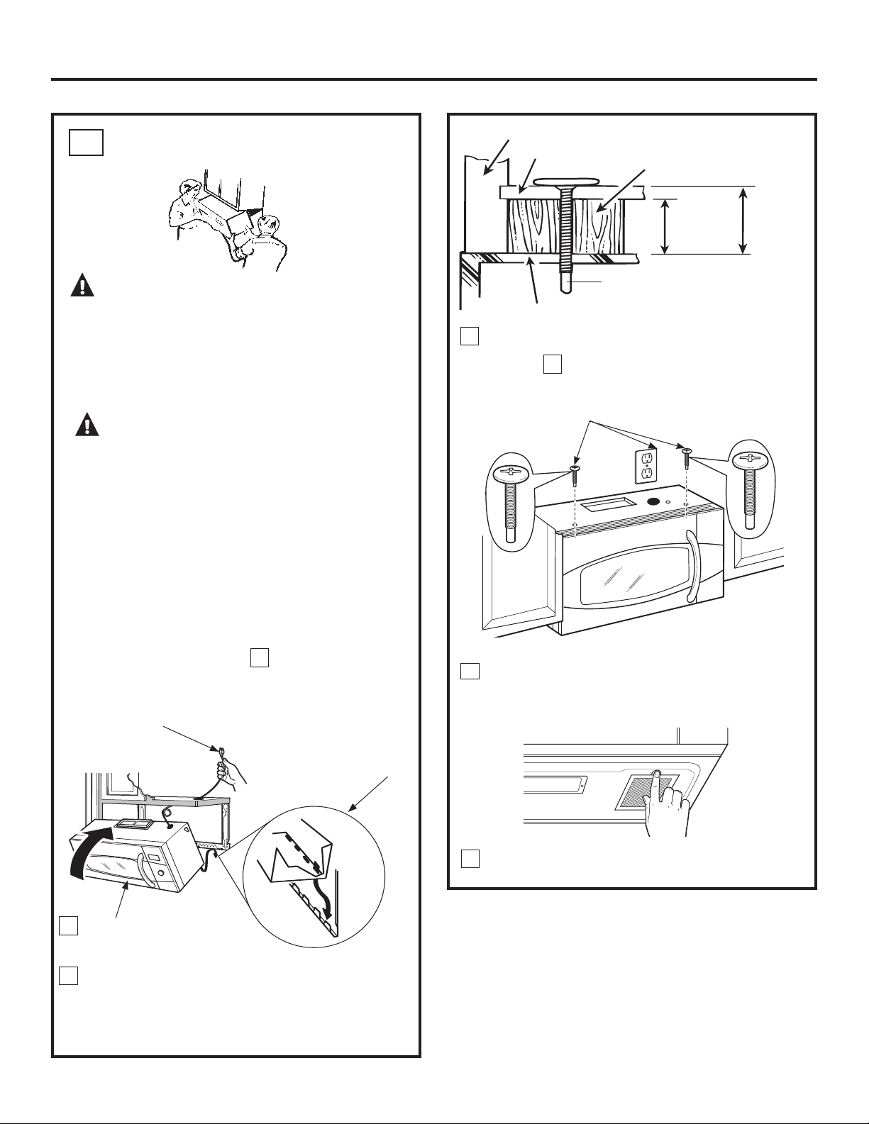
After locating the stud(s), find the center by probing
the wall with a small nail to find the edges of the stud.
Then place a mark halfway between the edges.
The center of any adjacent studs should be 16s or 24s
from this mark.
Draw a line down the center of the studs.
IMPORTANT: The microwave must be connected to at
least one wall stud.
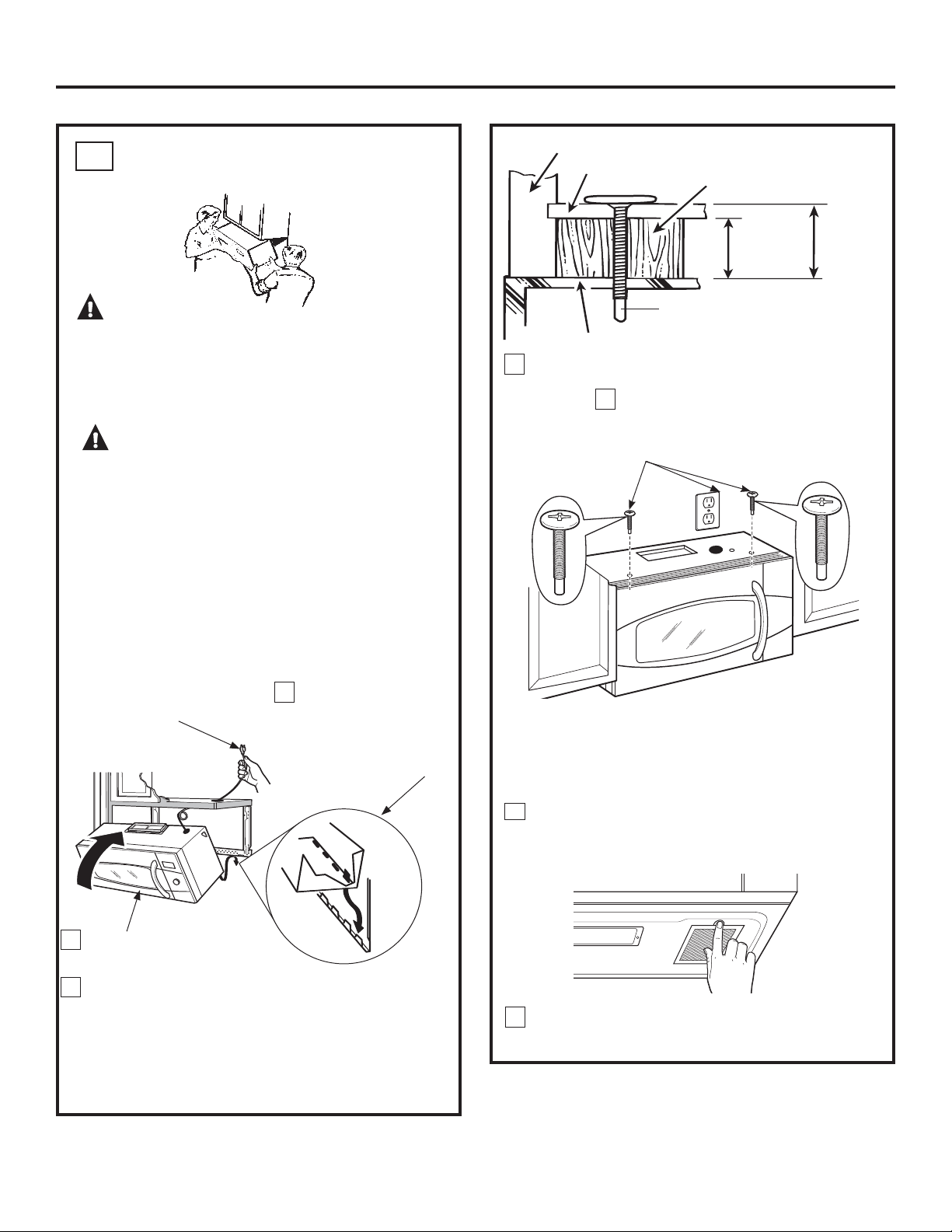
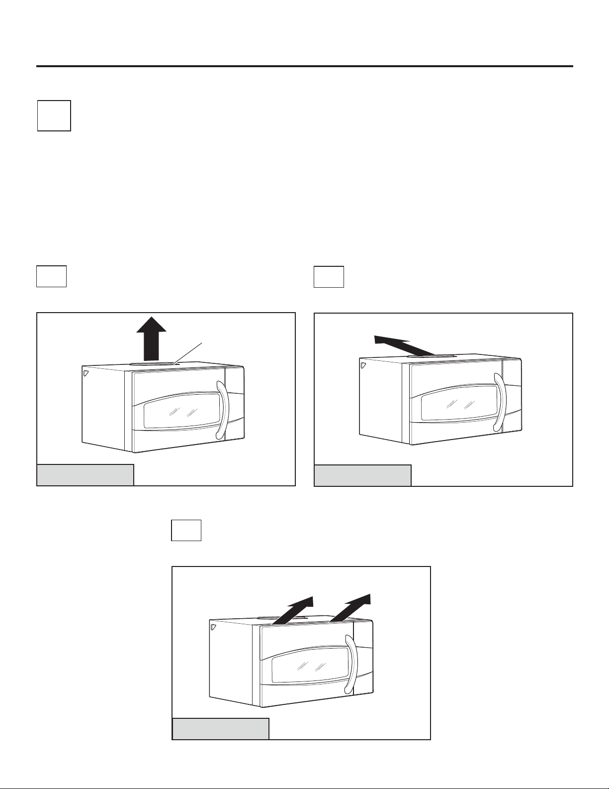
1
Remove the box containing the installation
instructions, filters, exhaust adaptor, damper
and the small hardware bag. Do not remove
the Styrofoam protecting the front of the oven.
Fold back all 4 carton flaps fully against carton sides.
Then carefully roll the oven and carton over onto
the top side. The oven should be resting in the
Styrofoam.
REMOVING THE OVEN FROM
THE CARTON/REMOVING
THE MOUNTING PLATE
FINDING THE WALL STUDS
B
A
2
PLACEMENT OF THE MOUNTING PLATE
1
Wall Studs
Center
3
Carton
Pull the carton up and off the oven.
Open the oven door and remove the styrofoam
pack from inside the oven. Remove the tape
covering the turntable hub.
Styrofoam
Installation Instructions
2
3
6
Set the oven upright. Remove and properly discard
plastic bags and Styrofoam.
1
The mounting plate is attached to the back of the
oven. Remove the two screws holding it to the oven.
The plate will be used as the rear wall template and
for mounting the oven to the wall.
4
5
1” = 2.5 cm; 1’ = 0.3 m

9
DETERMINING WALL PLATE LOCATION UNDER YOUR CABINET
C
Your cabinets may have decorative trim that interferes
with the oven installation. Remove the decorative trim
to install the oven properly and to make it level.
THE OVEN MUST BE LEVEL.
Use a level to make sure the cabinet bottom is level.
If the cabinets have a front overhang only, with no back
or side frame, install the mounting plate down the same
distance as the front overhang depth. This will keep
the oven level.
Measure the inside depth of the front overhang.
Draw a horizontal line on the back wall an equal
distance below the cabinet bottom as the inside depth
of the front overhang.
For this type of installation with front overhang only,
align the mounting tabs with this horizontal line, not
touching the cabinet bottom as described in Step D.
Plate position – beneath flat bottom
cabinet
Plate position – beneath recessed bottom
FDELQHWZLWKIURQWRYHUKDQJ
Mounting Plate Tabs
Touching the Cabinet
Bottom
Mounting Plate
with Tabs Below
Cabinet Bottom
the Same Distance
as the Front
Overhang Depth
At least 30s, up to 36s
Plate position – beneath framed recessed
cabinet bottom
Mounting Plate Tabs
Touching the Back
Frame
Installation Instructions
30s to Cooktop
30s to Cooktop
1
2
3
1” = 2.5 cm; 1’ = 0.3 m
10
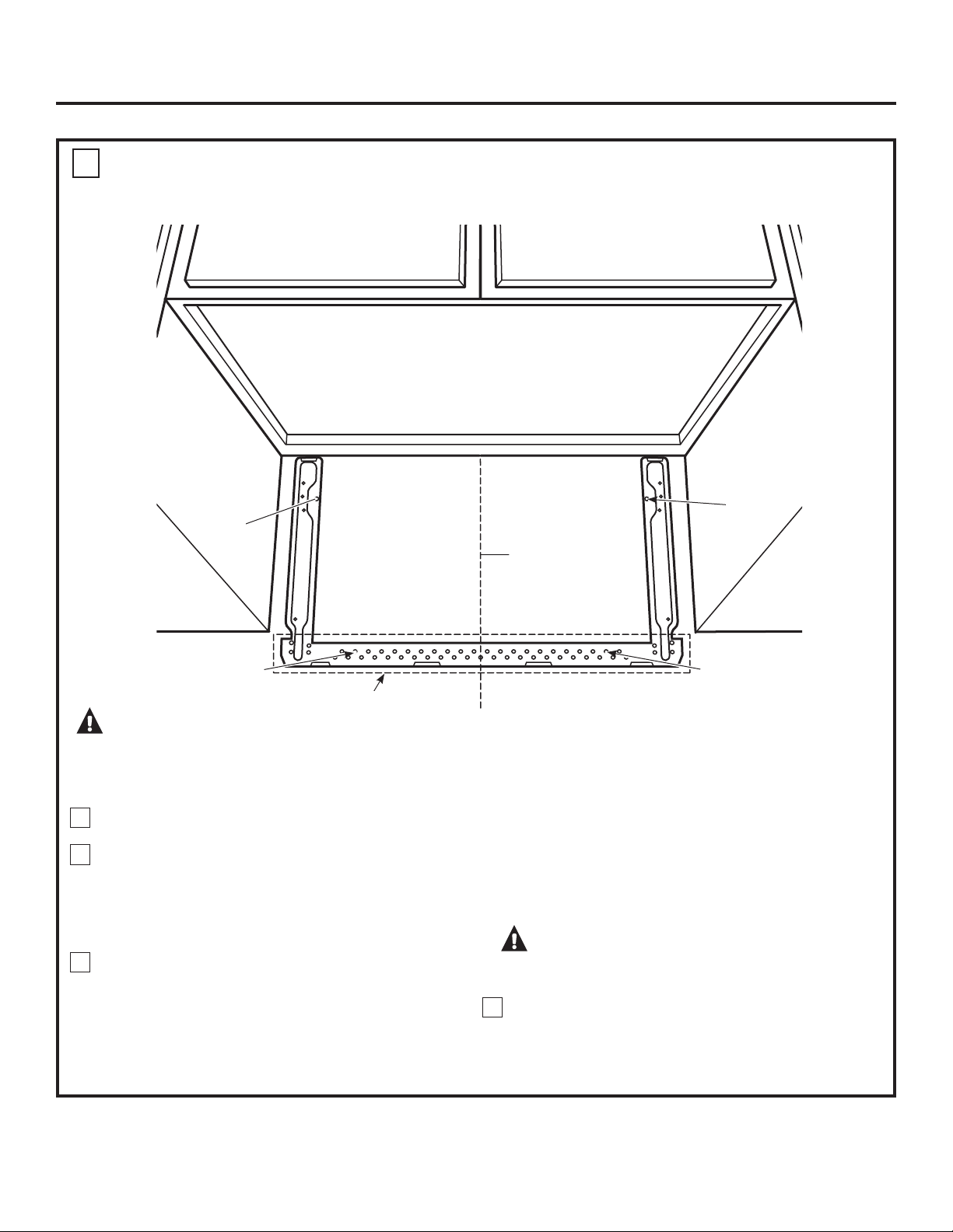
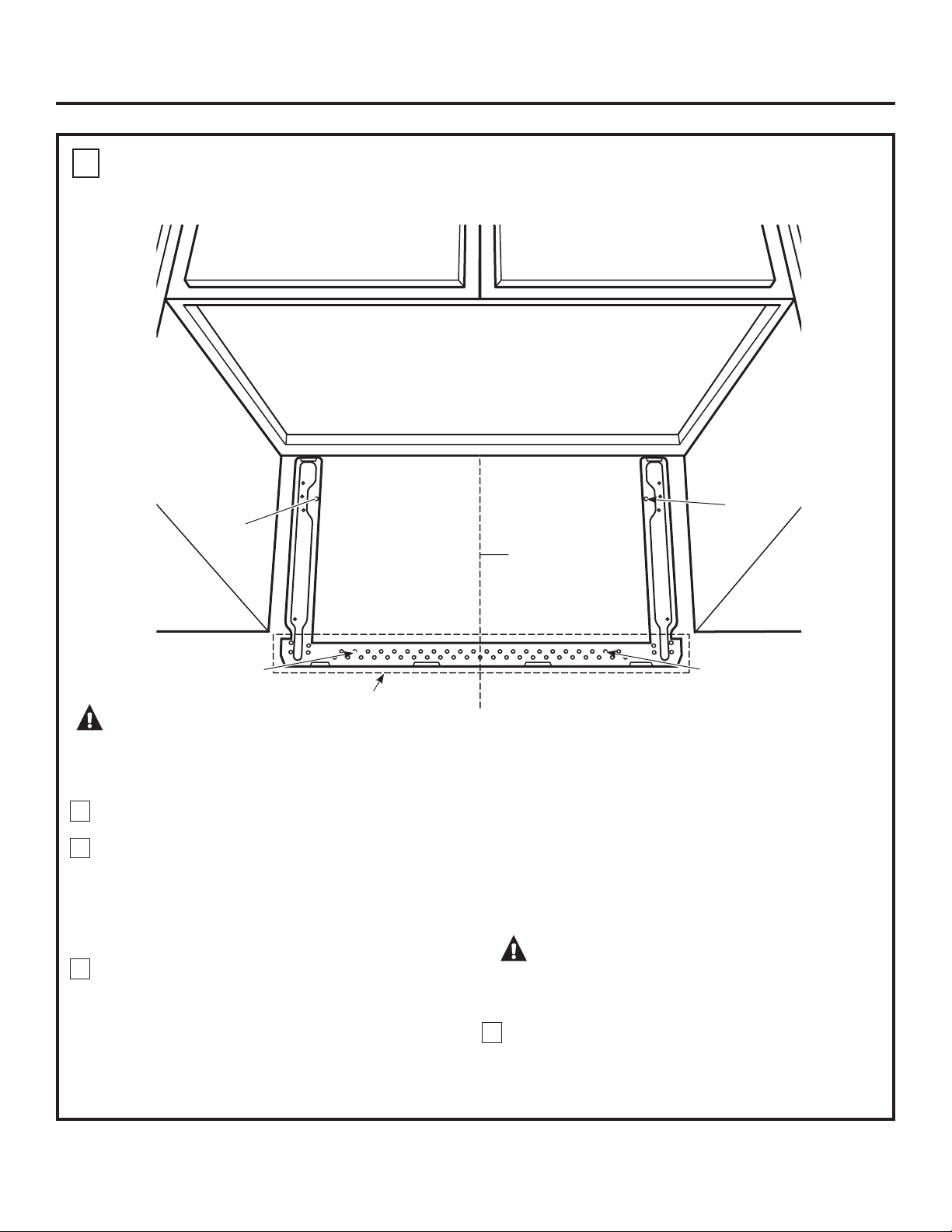
ALIGNING THE WALL PLATE
Draw a vertical line on the wall at the center of the 30s
wide space.
Use the mounting plate as the template for the rear wall.
Place the mounting plate on the wall, making sure that
the tabs are touching the bottom of the cabinet or
WKHOHYHOOLQHGUDZQLQ6WHS&IRUFDELQHWVZLWKIURQW
RYHUKDQJ/LQHXSWKHQRWFKDQGFHQWHUOLQHRQ
the mounting plate to the center line on the wall.
While holding the mounting plate with one hand, draw
circles on the wall at holes A, B, C and D (see illustration
above/actual plate marked with arrows) . Four holes
must be used for mounting.
NOTE: Holes C and D are inside area E. If neither C nor D
is in a stud, find a stud somewhere in area E and draw a
fifth circle to line up with the stud. It is important to use
at least one wood screw mounted firmly in a stud
to support the weight of the oven.
Set the mounting plate aside.
WARNING:5LVNRIHOHFWULFVKRFN&DQFDXVH
LQMXU\RUGHDWK7DNHFDUHWRQRWGULOOLQWRHOHFWULFDOZLULQJ
inside walls or cabinets.
Drill holes on the circles. If there is a stud, drill a
3
ø16s hole
for wood screws. For holes that don’t line up with a stud,
drill a
5
ø8s hole for toggle bolts.
NOTE: DO NOT MOUNT THE PLATE AT THIS TIME.
2
3
4
Draw a
Vertical Line
on Wall from
Center of Top
Cabinet
Area E
Hole A
Hole B
Hole D
Hole C
D
Installation Instructions
CAUTION:
:HDUJORYHVWRDYRLGFXWWLQJ
fingers on sharp edges.
1
1” = 2.5 cm; 1’ = 0.3 m

A
This oven is designed for adaptation to the following
3 types of ventilation:
A. Outside Top Exhaust (Vertical Duct)
%2XWVLGH%DFN([KDXVW+RUL]RQWDO'XFW
C. Recirculating (Non-Vented Ductless)
NOTE: This oven is shipped assembled for Outside Top
Exhaust. Select the type of ventilation required for your
installation and proceed to that section.
OUTSIDE TOP EXHAUST
(VERTICAL DUCT)
OUTSIDE BACK EXHAUST
(HORIZONTAL DUCT)
RECIRCULATING
(NON-VENTED DUCTLESS)
See page 12
See page 15
See page 19
A Charcoal Filter Accessory Kit
is required for the non-vented
exhaust. (See your Owner’s
Manual for the kit number.)
Adaptor in Place for
Outside Top Exhaust
Installation Instructions
2
B
C
11
INSTALLATION TYPES
(Choose A, B or C)
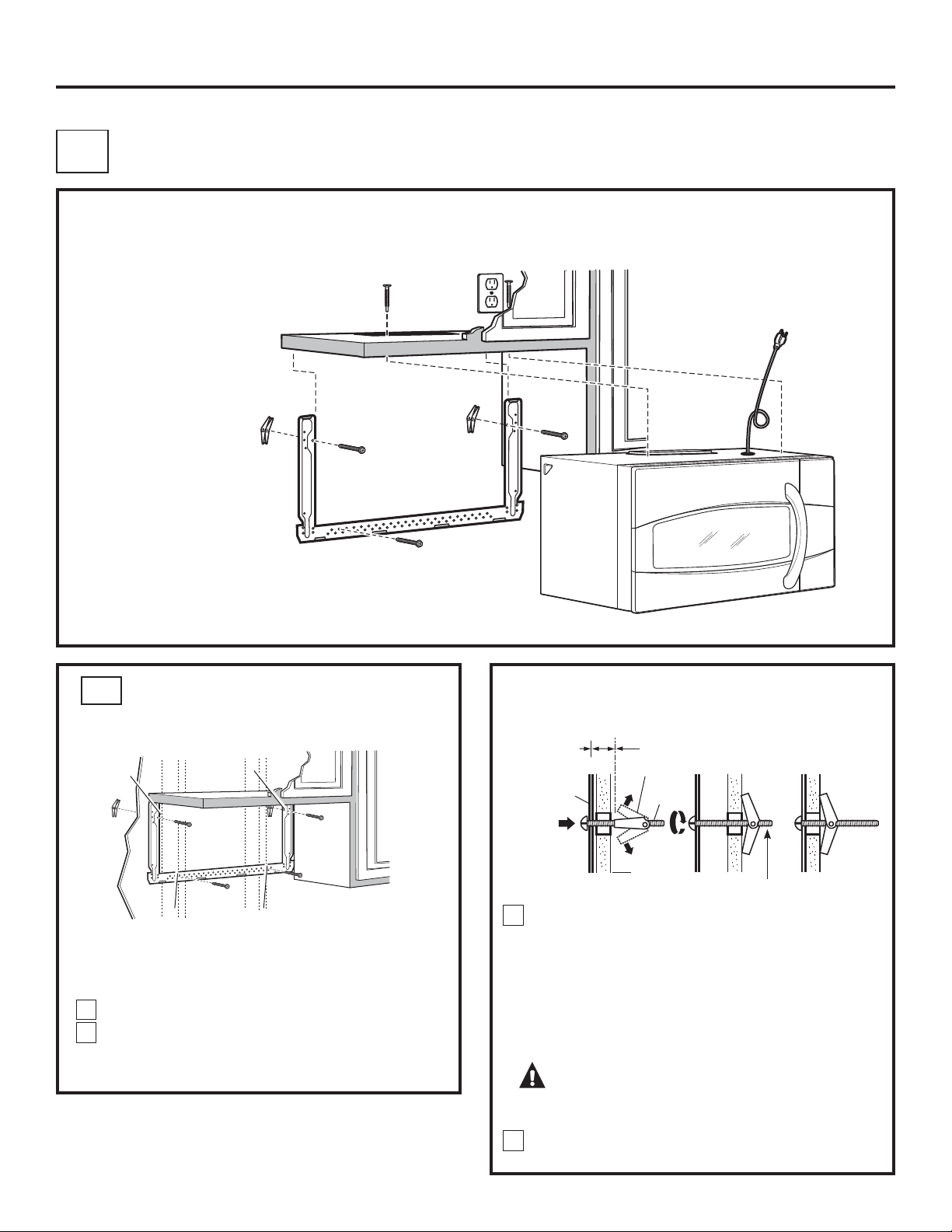
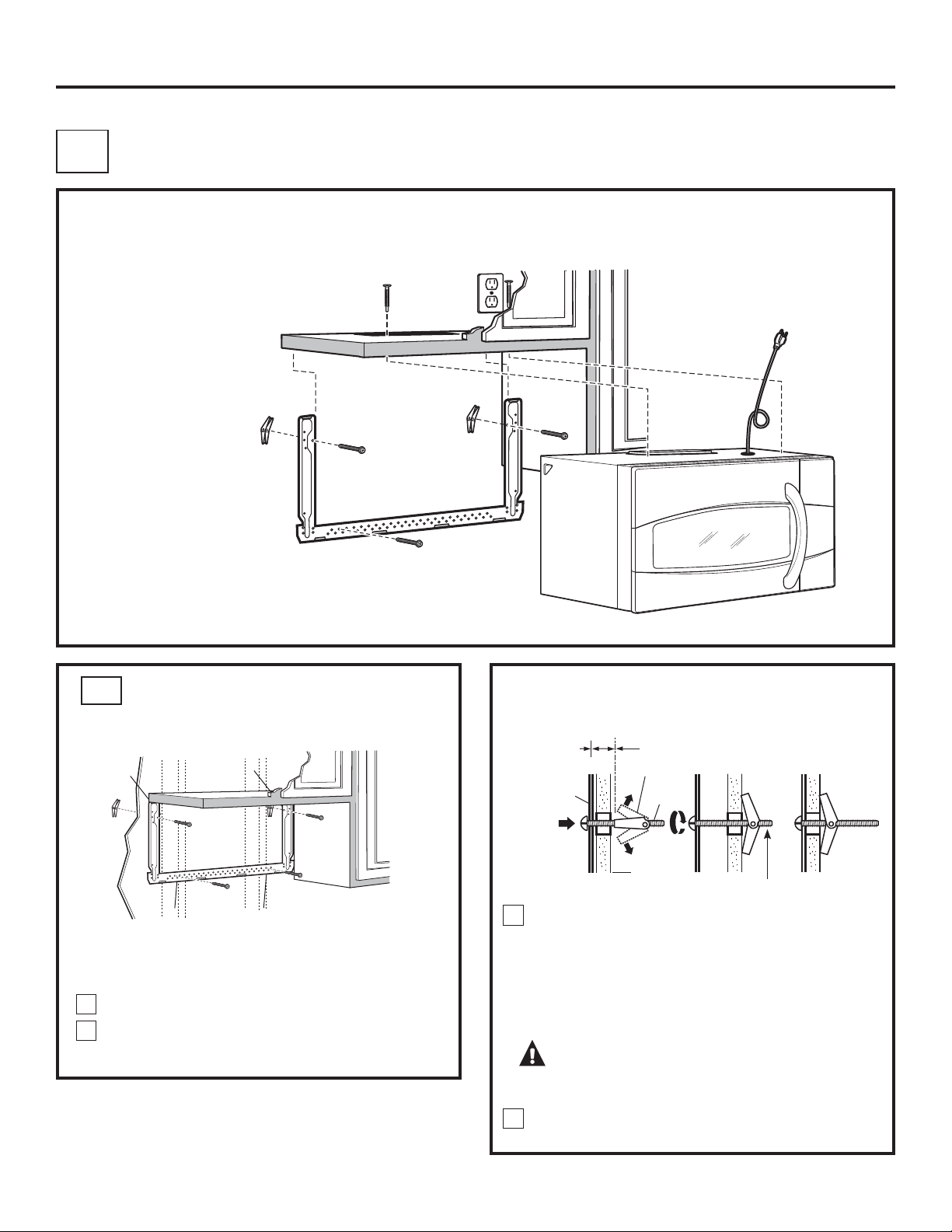
Place the mounting plate against the wall and insert
the toggle wings into the holes in the wall to mount
the plate.
NOTE: Before tightening toggle bolts and wood screw,
make sure the tabs on the mounting plate touch
the bottom of the cabinet when pushed flush against
the wall and that the plate is properly centered under
the cabinet.
CAUTION: %HFDUHIXOWRDYRLGSLQFKLQJ
ILQJHUVEHWZHHQWKHEDFNRIWKHPRXQWLQJSODWHDQG
the wall.
Tighten all bolts. Pull the plate away from the wall
to help tighten the bolts.
3
A
4
ATTACH THE MOUNTING PLATE
TO THE WALL
A1
12
OUTSIDE TOP EXHAUST
(Vertical Duct)
Attach the plate to the wall using toggle bolts. At least
one wood screw must be used to attach the plate to
a wall stud. Recommended locations on the mounting
plate are indicated by A, B, C and D.
Remove the toggle wings from the bolts.
Insert the bolts into the mounting plate through
the holes designated to go into drywall and reattach
the toggle wings to
3
ø4s onto each bolt.
1
INSTALLATION OVERVIEW
A1. Attach Mounting Plate to Wall
A2. Prepare Top Cabinet
A3. Install Adaptor
A4. Mount Oven
A5. Adjust Exhaust Adaptor
A6. Connect Ductwork
Wall
Mounting
Plate
Spacing for
Toggles More Than
Wall Thickness
Bolt End
Toggle
Bolt
Toggle Wings
To use toggle bolts:
Installation Instructions
2
A
B
C
D
1” = 2.5 cm; 1’ = 0.3 m
13
MOUNT THE OVEN
A4
ASSEMBLE AND INSTALL ADAPTOR
A3
USE TOP CABINET TEMPLATE FOR
PREPARATION OF TOP CABINET
You need to drill holes for the top support screws,
a hole large enough for the power cord to fit through,
and a cutout large enough for the exhaust adaptor.
A2
Damper
Front of Oven
Back of Oven
Remove Screw from
Back of Blower Plate
Remove Screw from
Top of Blower Plate
Read the instructions on the TOP CABINET TEMPLATE.
Tape it underneath the top cabinet.
Drill the holes, following the instructions on the TOP
CABINET TEMPLATE.
CAUTION: Wear safety goggles when
drilling holes in the cabinet bottom.
Installation Instructions
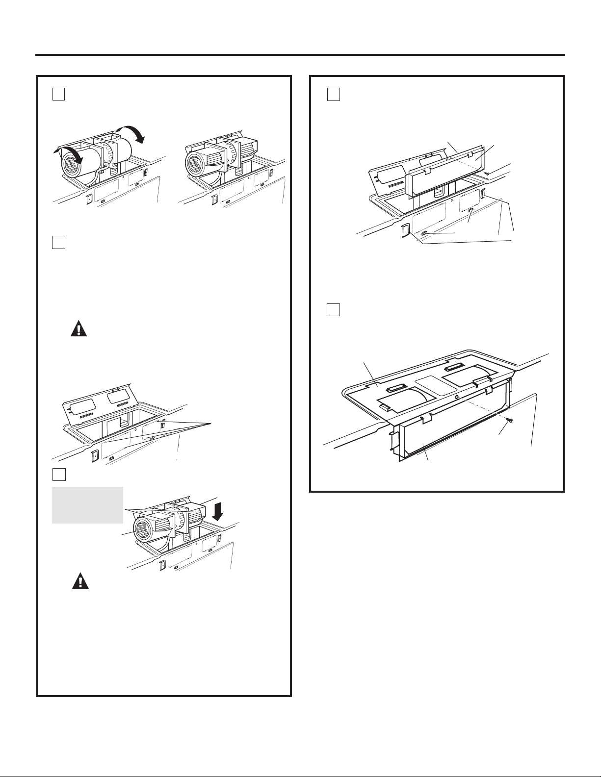
Place the oven in its upright position, with the top
of the unit facing up and the front of the unit facing
toward you.
Remove the screw on the back side of the blower
plate and raise the blower plate off of the microwave.
Slide the damper from left to right into the tabs on the
blower plate. The yellow tape on the damper should
be facing back. If the blower plate is not raised off of
the top of the microwave, the damper cannot slide
into position.
Remove the yellow tape from the damper. 0DNHVXUH
WKDWWKHGDPSHUSLYRWVHDVLO\EHIRUHPRXQWLQJRYHQ
You will need to make adjustments to assure proper
alignment with your house exhaust duct after the
oven is installed.
Exhaust
Adaptor
1
2
Blower Plate
Tabs
3
4
CAUTION: 7RDYRLGWKHULVNRISHUVRQDO
LQMXU\EDFNLQMXU\RURWKHULQMXULHVGXHWRH[FHVVLYH
ZHLJKWRIWKHPLFURZDYHRUSURSHUW\GDPDJH\RX
ZLOOQHHGWZRSHRSOHWRLQVWDOOWKLVPLFURZDYH
IMPORTANT: Do not grip or use handle during
installation.
WARNING: 5LVNRI(OHFWULF6KRFN&DQ
cause injury or death: If installing unit with metal
FRXQWHUWRSVFRYHUWKHHGJHRIWKHSRZHUVXSSO\
cord hole with the power supply cord bushing.
IMPORTANT: If filler blocks are not used, case damage
may occur from overtightening screws.
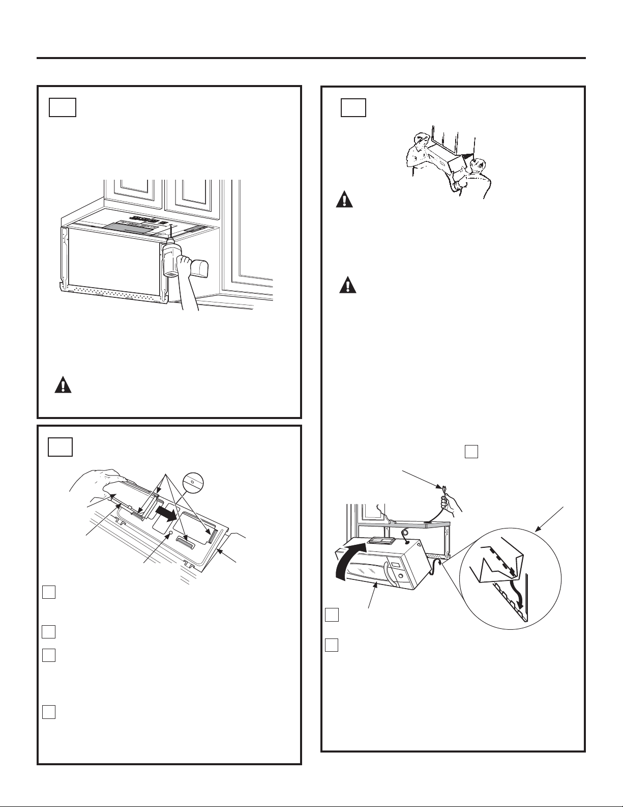
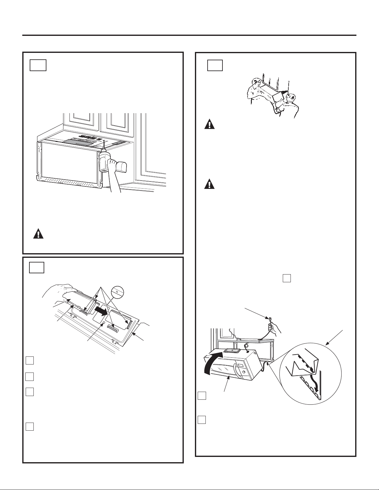
Insert a self-aligning screw through top-center
cabinet hole. Temporarily secure the oven by
turning the screw at least two full turns after
the threads have engaged. (It will be completely
tightened later.)
3
NOTE: When mounting
the microwave, thread
power cord through hole
in bottom of top cabinet.
Keep it tight throughout
Steps 1–3. Do not pinch
cord or lift oven by pulling
cord.
Lift microwave, tilt it
forward, and hook slots
at back bottom edge
onto four lower tabs of
mounting plate.
1
2
Rotate front of oven up
against cabinet bottom.

CONNECTING DUCTWORK
14
3
Attach the oven to the top cabinet.
Cabinet Front
Cabinet Bottom Shelf
Filler Block
Oven Top
Equivalent
to Depth
of Cabinet
Recess
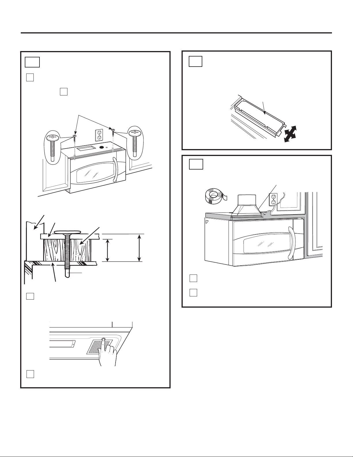
Insert 2 self-aligning screws
(
1
ø4s-28 x 2
5
/8
s
) through outer
top cabinet holes. Turn two full
turns on each screw.
Tighten the outer two screws to the top of the oven.
(While tightening screws, hold the oven in place
against the wall and the top cabinet.)
6
5
Install grease filters. See the Owner’s Manual
packed with the oven.
Installation Instructions
ADJUST THE EXHAUST ADAPTOR
A5
Open the top cabinet and adjust the exhaust adaptor
to connect to the house duct.
Back of Oven
Damper
1
2
Extend the house duct down to connect to
the exhaust adaptor.
Seal exhaust duct joints using duct tape.
House Duct
Self-Aligning Screw
4
MOUNT THE OVEN (continued)
A4
A6
This distance
can NOT
exceed 2”
to ensure
proper
installation
1” = 2.5 cm; 1’ = 0.3 m
OUTSIDE BACK EXHAUST
(Horizontal Duct)
PREPARING THE REAR WALL
FOR OUTSIDE BACK EXHAUST
B1
INSTALLATION OVERVIEW
B1. Prepare Rear Wall
B2. Attach Mounting Plate to Wall
B3. Prepare Top Cabinet
B4. Adjust Blower
B5. Mount the Oven
Installation Instructions
B
15
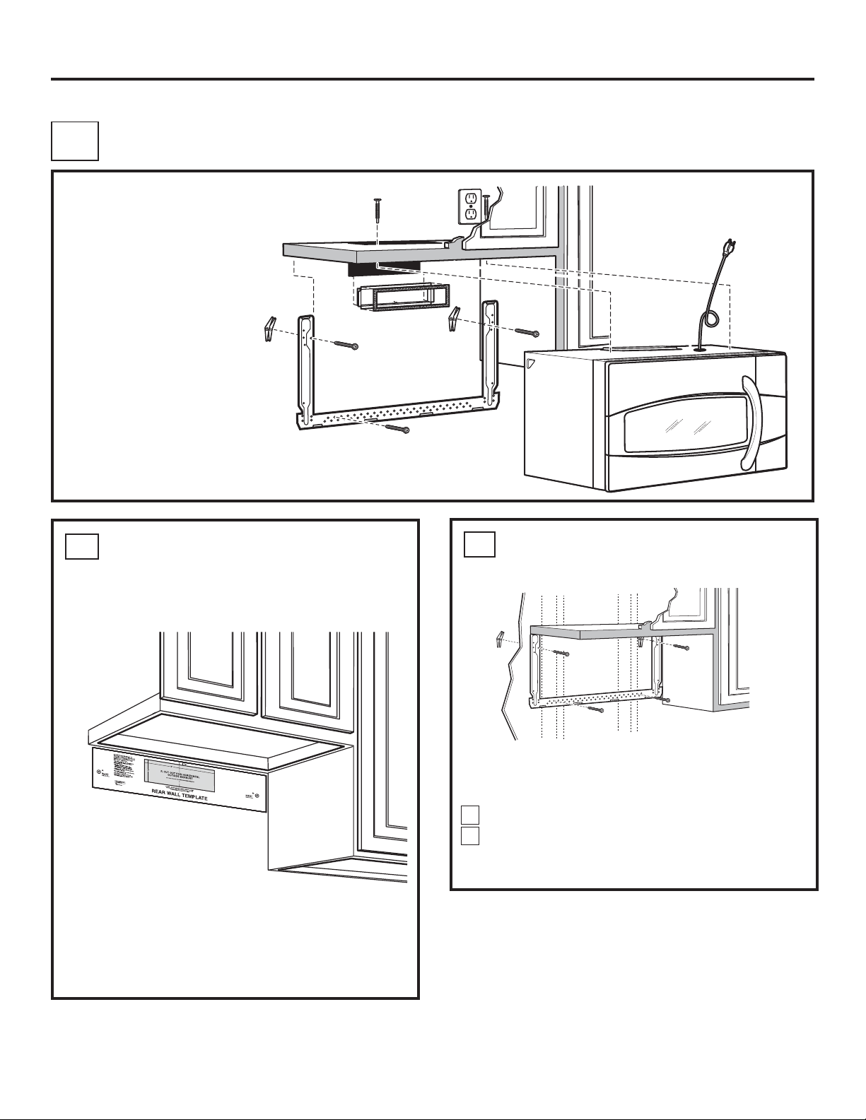
ATTACH THE MOUNTING PLATE
TO THE WALL
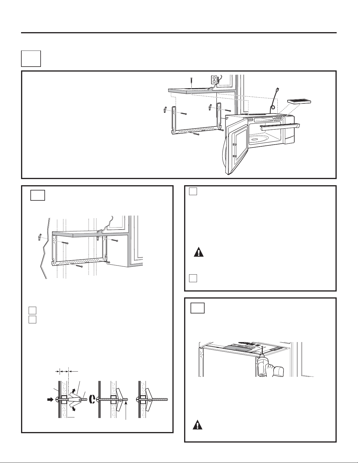
B2
Attach the plate to the wall using toggle bolts. At least
one wood screw must be used to attach the plate to
a wall stud.
Remove the toggle wings from the bolts.
Insert the bolts into the mounting plate through
the holes designated to go into drywall and reattach
the toggle wings to
3
ø4s onto each bolt.
1
2
You need to cut an opening in the rear wall for outside
exhaust.
Read the instructions on the REAR WALL TEMPLATE.
Tape it to the rear wall, lining up with the holes
previously drilled for holes A and B in the wall plate.
Cut the opening, following the instructions of the
REAR WALL TEMPLATE.
1” = 2.5 cm; 1’ = 0.3 m
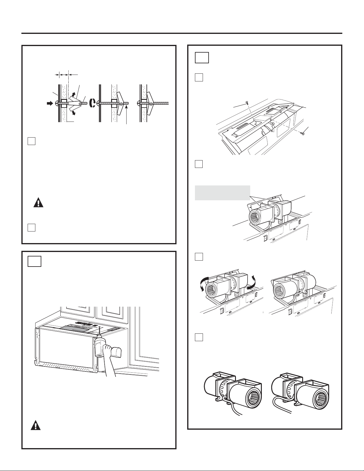
BEFORE: Fan Blade
Openings Facing Up
4
3
2
1
Remove the blower motor screw that holds the
blower plate to the oven. Lift the front of the blower
plate to install the blower.
ADAPTING BLOWER FOR
OUTSIDE BACK EXHAUST
B4
End B
End A
Carefully pull out the blower unit. The wires
will extend far enough to allow you to adjust
the blower unit.
Rotate blower unit counterclockwise 180°.
Before Rotation After Rotation
Gently remove the wires from the grooves.
Reroute the wires through grooves on other side
of the blower unit.
Before Rerouting After Rerouting
Wires Routed Through Right
Side
Wires Routed Through Left
Side
Blower Plate
Back of
Oven
Back of
Oven
Blower
Motor Screw
Blower
Motor Screw
16
USE TOP CABINET TEMPLATE
FOR PREPARATION OF TOP
CABINET
B3
Read the instructions on the TOP CABINET
TEMPLATE.
Tape it underneath the top cabinet.
Drill the holes, following the instructions on the
TOP CABINET TEMPLATE.
CAUTION: Wear safety goggles when
drilling holes in the cabinet bottom.
Wall
Mounting
Plate
Spacing for Toggles More
Than Wall Thickness
Toggle
Bolt
Toggle Wings
To use toggle bolts:
Bolt End
Installation Instructions
You need to drill holes for the top support screws and
a hole large enough for the power cord to fit through.
Place the mounting plate against the wall and insert
the toggle wings into the holes in the wall to mount
the plate.
NOTE: Before tightening toggle bolts and wood screw,
make sure the tabs on the mounting plate touch
the bottom of the cabinet when pushed flush against
the wall and that the plate is properly centered under
the cabinet.
CAUTION:%HFDUHIXOWRDYRLGSLQFKLQJ
ILQJHUVEHWZHHQWKHEDFNRIWKHPRXQWLQJSODWHDQG
the wall.
Tighten all bolts. Pull the plate away from the wall
to help tighten the bolts.
3
4
Snip all 4 webs
on each knockout
panel and
remove the metal
knockouts for rear
airflow.
Locate the two “knockout” plates, on the rear oven
panel, near the top of the oven.
Using tin snips, carefully cut the web area from the
two holes side-by-side (that secure the knockouts to
the oven). Cut all four webs on both rear knockouts;
this will allow the ventilation fan airflow to exhaust
out the rear of the oven.
CAUTION: Be sure to trim the sharp
HGJHVIURPWKHRSHQLQJVDIWHUUHPRYLQJWKH
NQRFNRXWSODWHV
AFTER: Fan Blade
Openings Facing
%DFN
7
Place the blower unit back into the opening.
9
8
Roll the blower unit 90° so that fan blade openings
are facing out the back of the oven.
5
17
Blower Plate
Before Rolling
After Rolling
Back of
Oven
End A
End B
Back of
Oven
Back of
Oven
WARNING:5LVNRIHOHFWULFVKRFN
can cause injury or death. Do not pull or stretch
WKHEORZHUXQLWZLULQJPDNHVXUHWKHZLUHVDUH
not pinched.
NOTE: The blower unit exhaust openings should
match exhaust openings on rear of microwave.
Installation Instructions
2YHQ5HDU3DQHO
6
Attach the exhaust adaptor to the rear of the oven
by sliding it into the guides at the top center of the
back of the oven.
Close the blower plate so it is closed over the top
tab of the exhaust adapter. Secure with the screw
removed earlier.
Push down securely until it is in the lower locking
tabs. Take care to assure the damper hinge
is installed so that it is at the top and that the
damper swings freely.
Slide
exhaust
adaptor into
guides on
oven rear.
Exhaust Adaptor
Exhaust Adaptor
Damper
(hinge side up)
Locking
Tabs
Guides
Back of
Oven
Screw
Screw
Attach the oven to the top cabinet.
18
Installation Instructions
MOUNT THE OVEN
B5
7
5
Cabinet Front
6
Tighten the outer two screws to the top of the
oven. (While tightening screws, hold the oven
in place against the wall and the top cabinet.)
Insert 2 self-aligning screws
(
1
ø4s-28 x 2
5
/8s) through outer
top cabinet holes. Turn two full
turns on each screw.
Install grease filters. See the Owner’s Manual
packed with the oven.
4
CAUTION: 7RDYRLGWKHULVNRISHUVRQDO
LQMXU\EDFNLQMXU\RURWKHULQMXULHVGXHWRH[FHVVLYH
ZHLJKWRIWKHPLFURZDYHRUSURSHUW\GDPDJH\RX
ZLOOQHHGWZRSHRSOHWRLQVWDOOWKLVPLFURZDYH
IMPORTANT: Do not grip or use handle during
installation.
WARNING: 5LVNRI(OHFWULF6KRFN&DQ
cause injury or death: If installing unit with metal
FRXQWHUWRSVFRYHUWKHHGJHRIWKHSRZHUVXSSO\
cord hole with the power supply cord bushing.
IMPORTANT: If filler blocks are not used, case damage
may occur from overtightening screws.
Insert a self-aligning screw through top-center
cabinet hole. Temporarily secure the oven by
turning the screw at least two full turns after
the threads have engaged. (It will be completely
tightened later.)
NOTE: When mounting
the microwave, thread
power cord through hole
in bottom of top cabinet.
Keep it tight throughout
Steps 1–3. Do not pinch
cord or lift oven by pulling
cord.
Lift microwave, tilt it
forward, and hook slots
at back bottom edge
onto four lower tabs of
mounting plate.
1
Rotate front of oven up
against cabinet bottom.
2
3
Cabinet Bottom Shelf
Filler Block
Oven Top
Equivalent
to Depth
of Cabinet
Recess
Self-Aligning Screw
This distance
can NOT
exceed 2”
to ensure
proper
installation
1” = 2.5 cm; 1’ = 0.3 m
USE TOP CABINET TEMPLATE
FOR PREPARATION OF TOP CABINET
C2
19
RECIRCULATING (Non-Vented Ductless)
INSTALLATION OVERVIEW
C1. Attach Mounting Plate to Wall
C2. Prepare Top Cabinet
C3. Adjust Blower
C4. Mount the Oven
C5. Install Charcoal Filter (not supplied)
Read the instructions on the TOP CABINET
TEMPLATE.
Tape it underneath the top cabinet.
Drill the holes, following the instructions on the TOP
CABINET TEMPLATE.
CAUTION: Wear safety goggles when
drilling holes in the cabinet bottom.
Installation Instructions
You need to drill holes for the top support screws and
a hole large enough for the power cord to fit through.
C
Place the mounting plate against the wall and insert
the toggle wings into the holes in the wall to mount
the plate.
NOTE: Before tightening toggle bolts and wood screw,
make sure the tabs on the mounting plate touch the
bottom of the cabinet when pushed flush against the
wall and that the plate is properly centered under the
cabinet.
CAUTION:%HFDUHIXOWRDYRLGSLQFKLQJ
ILQJHUVEHWZHHQWKHEDFNRIWKHPRXQWLQJSODWHDQG
the wall.
Tighten all bolts. Pull the plate away from the wall
to help tighten the bolts.
3
ATTACH THE MOUNTING PLATE
TO THE WALL
C1
Attach the plate to the wall using toggle bolts. At least
one wood screw must be used to attach the plate to
a wall stud.
Remove the toggle wings from the bolts.
Insert the bolts into the mounting plate through
the holes designated to go into drywall and reattach
the toggle wings to
3
ø4s onto each bolt.
1
4
Wall
Mounting
Plate
Spacing for
Toggles More Than
Wall Thickness
Bolt End
Toggle
Bolt
Toggle Wings
To use toggle bolts:
2
1” = 2.5 cm; 1’ = 0.3 m
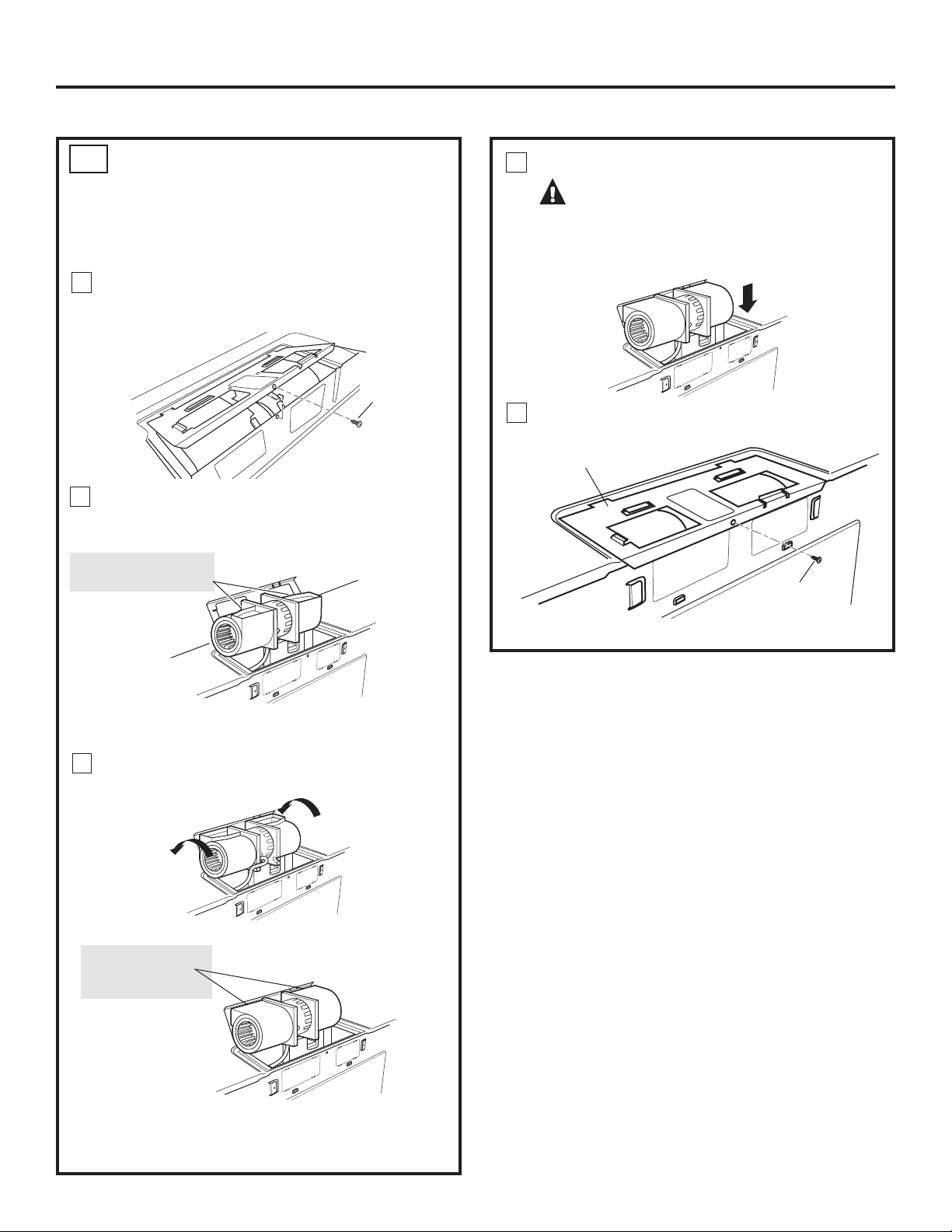
Place the blower unit back into the opening.
WARNING:5LVNRIHOHFWULFVKRFN
can cause injury or death. Do not pull or stretch
WKHEORZHUXQLWZLULQJ0DNHVXUHWKHZLUHGDUH
not pinched.
5
4
AFTER: Fan Blade
Openings Facing
Forward
ADAPTING BLOWER
FOR RECIRCULATION
C3
20
NOTE: The exhaust adaptor with damper is not
needed for recirculating models. You may want
to save them for possible future use.
Carefully pull out the blower unit. The wires
will extend far enough to allow you to adjust
the blower unit.
NOTE: Make sure wires remain routed in the grooves
of the motor frame.
Installation Instructions
1
Blower Plate
Blower
Motor Screw
BEFORE: Fan Blade
Openings Facing Up
2
End B
End A
Carefully pull out the blower unit. The wires
will extend far enough to allow you to adjust
the blower unit.
Roll the blower unit 90° so that fan blade openings
are facing out the back of the oven.
3
Back of
Oven
Back of
Oven
Blower Plate
Back of
Oven
Screw
Close the blower plate. Secure with the screw
removed earlier.
21
Installation Instructions
C4
CAUTION: 7RDYRLGWKHULVNRISHUVRQDO
LQMXU\EDFNLQMXU\RURWKHULQMXULHVGXHWRH[FHVVLYH
ZHLJKWRIWKHPLFURZDYHRUSURSHUW\GDPDJH\RX
ZLOOQHHGWZRSHRSOHWRLQVWDOOWKLVPLFURZDYH
IMPORTANT: Do not grip or use handle during
installation.
WARNING: 5LVNRI(OHFWULF6KRFN&DQ
cause injury or death: If installing unit with metal
FRXQWHUWRSVFRYHUWKHHGJHRIWKHSRZHUVXSSO\
cord hole with the power supply cord bushing.
IMPORTANT: If filler blocks are not used, case damage
may occur from overtightening screws.
NOTE: When mounting
the microwave, thread
power cord through hole
in bottom of top cabinet.
Keep it tight throughout
Steps 1–3. Do not pinch
cord or lift oven by pulling
cord.
Lift microwave, tilt it
forward, and hook slots
at back bottom edge
onto four lower tabs of
mounting plate.
1
2
Rotate front of oven up
against cabinet bottom.
MOUNT THE OVEN
4
6
5
Tighten the outer two screws to the top of the
oven. (While tightening screws, hold the oven
in place against the wall and the top cabinet.)
Insert 2 self-aligning screws
(
1
ø4s-28 x 2
5
/8”) through outer
top cabinet holes. Turn two full
turns on each screw.
Install grease filters. See the Owner’s Manual
packed with the oven.
Insert a self-aligning screw through top-center
cabinet hole. Temporarily secure the oven by
turning the screw at least two full turns after
the threads have engaged. (It will be completely
tightened later.)
3
Cabinet Front
Cabinet Bottom Shelf
Filler Block
Oven Top
Equivalent
to Depth
of Cabinet
Recess
Self-Aligning Screw
This distance
can NOT
exceed 2”
to ensure
proper
installation
1” = 2.5 cm; 1’ = 0.3 m
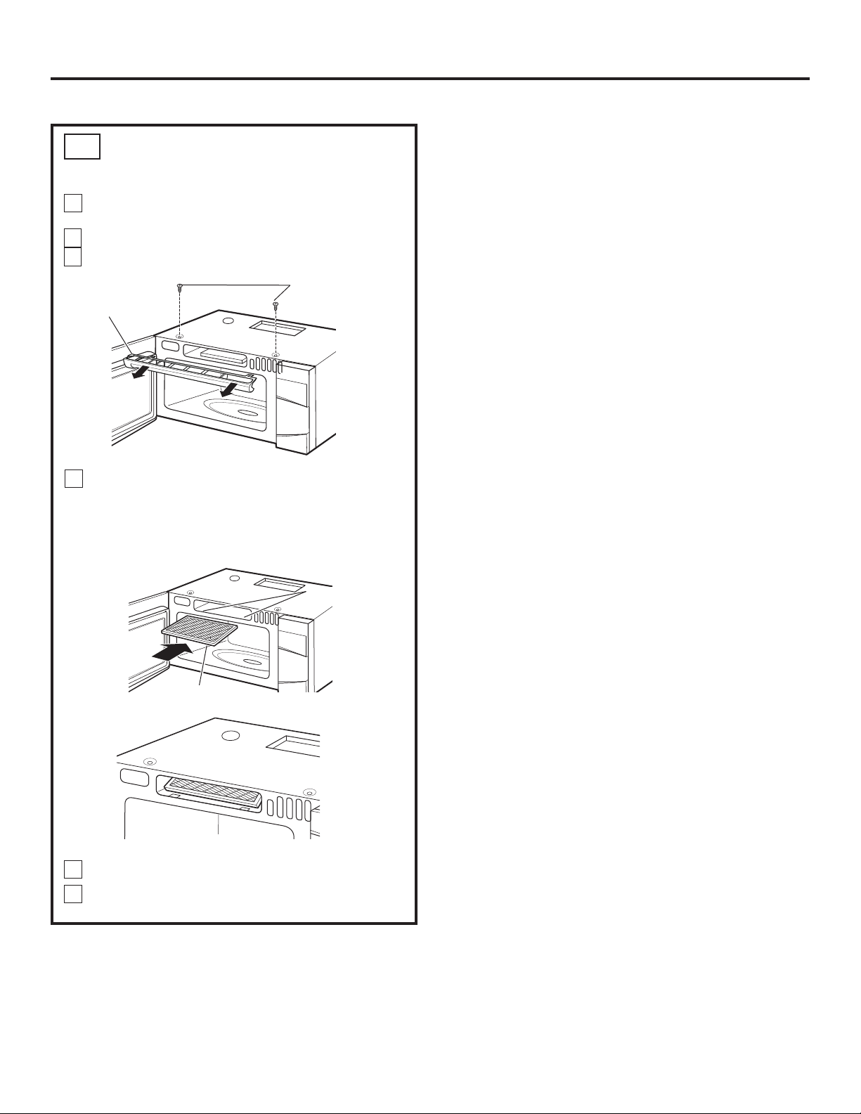
Remove 2 screws on top of oven, just above
the grille panel, using a Phillips screwdriver.
Open the door.
Remove the grille.
Insert the filter into the oven as shown until it fits
squarely into place. It will rest at an angle behind
the front lower tabs. When properly installed,
the wire mesh of the filter should be visible
from the front.
2
1
INSTALLING THE CHARCOAL
FILTER
C5
22
Screws
Installation Instructions
4
Replace the grille and the 2 top screws.
Close the door and replace left side screw.
5
6
3
Grille
Front lower tabs
Charcoal filter
Charcoal filter installed
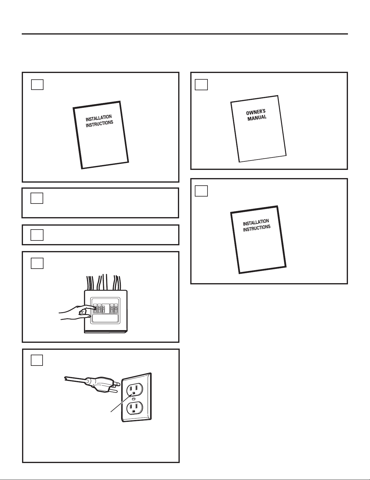
KEEP INSTALLATION INSTRUCTIONS
FOR THE LOCAL INSPECTOR’S USE.
120 V Models: Plug power cord into
a dedicated 15- to 20-amp electrical outlet.
7
Read the Owner’s Manual.
6
Replace house fuse or turn breaker back on.
4
Remove all packing material from the oven.
2
Make sure the oven has been installed
according to instructions.
1
23
BEFORE YOU USE YOUR OVEN
Ensure proper
ground exists
before use.
Installation Instructions
Install turntable and wheeled ring in cavity.
3
5
Where a standard two-prong wall receptacle
is encountered, it is very important to have it
replaced with a properly grounded three-prong
wall receptacle, installed by a qualified
electrician.

Printed in Korea
24

Instructions
d’installation
Des questions? Téléphonez au 1-800-561-3344 ou visitez notre site Web à l'adresse : www.electromenagersge.ca
VEUILLEZ LIRE ATTENTIVEMENT.
CONSERVEZ CES INSTRUCTIONS.
Lisez attentivement toutes ces instructions.
IMPORTANT – Conservez ces instructions pour
l'inspecteur local.
IMPORTANT – Observez tous les codes et
règlements en vigueur.
Remarque destinée à l'installateur – Veillez à
laisser ces instructions au consommateur.
AVANT DE COMMENCER
Remarque destinée au consommateur –
Conservez ces instructions pour vous y reporter
ultérieurement.
1LYHDXGHFRPSpWHQFH – L'installation de cet appareil
nécessite des compétences de base en mécanique et en
électricité.
L'installateur est responsable de la qualité de l'installation.
Une panne du produit due à une mauvaise installation n'est
pas couverte par la garantie.
Four à micro-ondes
à hotte intégrée
PVM9195 et PVM9215
350A4502P759
49-40732 (07-14)
26
Recyclage d'air................................................... 43 à 46
Fixation de la plaque de montage au mur ....43
Préparation de l’armoire supérieure ............... 43
Adaptation du ventilateur pour
le recyclage d'air .........................................44, 45
Installation du four ............................................45
Installation du filtre à charbon ........................46
Avant d’utiliser votre four ......................................................47
TABLE DES MATIÈRES
Renseignements généraux
&RQVLJQHVGHVpFXULWpLPSRUWDQWHV ....................................... 27
Exigences électriques ............................................................... 27
Évacuation de la hotte ...................................................... 28, 29
'RPPDJHV([SpGLWLRQLQVWDOODWLRQ..................................... 30
3LqFHVFRPSULVHV ....................................................................... 30
Outils nécessaires ..................................................................... 31
'pJDJHPHQWVSRXUO·LQVWDOODWLRQ ............................................ 31
*XLGHG·LQVWDOODWLRQpWDSHSDUpWDSH
0LVHHQSODFHGHODSODTXHGHPRQWDJH ...................... 32 à 34
Enlèvement de la plaque de montage ...................... 32
Localisation des montants ........................................... 32
Établissement de l’emplacement
de la plaque murale ..................................................... 33
Alignement de la plaque murale .................................34
7\SHVG·LQVWDOODWLRQ .......................................................... 35 à 46
Évacuation à l’extérieur par le dessus ...............36 à 38
Fixation de la plaque de montage au mur .....36
Préparation de l’armoire supérieure ................37
Montage et installation de l'adaptateur .......... 37
Installation du four ...................................... 37, 38
Ajustement de l’adaptateur d’évacuation ....... 38
Connexion au conduit........................................38
Évacuation à l’extérieur par l’arrière ................. 39 à 42
Préparation du mur arrière pour
l’évacuation à l’extérieur par l’arrière ..............39
Fixation de la plaque de montage au mur ... 39, 40
Préparation de l’armoire supérieure ................40
Adaptation du ventilateur pour
l’évacuation à l’extérieur par l’arrière ....... 40, 41
Installation du four ............................................. 42
A
B
C
Instructions d’installation

Avant d’entreprendre l’installation, un électricien qualifié doit
vérifier la continuité à la prise murale pour s’assurer qu’elle
est adéquatement mise à la terre. Si ce n’est pas le cas, ou
si la prise murale ne répond pas aux exigences électriques
indiquées (à la section EXIGENCES ÉLECTRIQUES), il faut faire
appel à un électricien qualifié pour corriger tout défaut.
AVERTISSEMENT :
Risque de choc électrique.
Peut entraîner des blessures
ou la mort : Enlevez le fusible
ou déclenchez le disjoncteur
DXSDQQHDXGHGLVWULEXWLRQ
SULQFLSDODYDQWG·HQWUHSUHQGUH
O·LQVWDOODWLRQD¿QG·pYLWHU
toute blessure grave ou
PRUWHOOHLPSXWDEOHjXQFKRF
électrique.
AVERTISSEMENT : Risque de choc électrique.
Peut entraîner des blessures ou la mort : CET APPAREIL DOIT
ÊTRE CONVENABLEMENT MIS À LA TERRE SRXUpYLWHUXQFKRF
grave ou mortel.
Modèles de 120 V
Pour diminuer les risques de
choc électrique, le cordon
G·DOLPHQWDWLRQGHFHWDSSDUHLO
est muni d’une fiche à trois
broches (mise à la terre) qui
FRUUHVSRQGjXQHSULVHPXUDOH
jWURLVDOYpROHVSULVHPLVHj
la terre).
CONSIGNES DE SÉCURITÉ IMPORTANTES
27
EXIGENCES ÉLECTRIQUES
Instructions d’installation
6LODSULVHPXUDOHHVWGXW\SHVWDQGDUGjGHX[DOYpROHV
LOIDXWODIDLUHUHPSODFHUSDUXQHSULVHjWURLVDOYpROHV
correctement mise à la terre, en vous adressant à un
électricien qualifié.
AVERTISSEMENT : Risque de choc électrique.
Peut entraîner des blessures ou la mort : NE COUPEZ, NE
DÉFORMEZ ET NE RETIREZ en aucun cas la troisième broche
PLVHjODWHUUHGHOD¿FKHGXFRUGRQG·DOLPHQWDWLRQ
1XWLOLVH]SDVGHFRUGRQSURORQJDWHXU/HQRQUHVSHFWGHFHV
FRQVLJQHVSHXWFDXVHUXQLQFHQGLH
Modèles de 120 V
Ce produit exige une prise de courant à trois alvéoles, mise à
la terre. Les caractéristiques nominales de ce produit sont :
120 V CA, 60 Hz, 13,5 A et 1,50 kW. Ce produit doit être branché à
un circuit d’alimentation de tension et de fréquence appropriées.
La taille des fils doit être conforme aux exigences du Code
national de l’électricité ou du code local en vigueur pour cette
puissance nominale. La fiche du cordon d’alimentation doit être
branchée dans une prise de courant distincte mise à la terre, de
15 ou 20 ampères. La boîte de la prise doit être aménagée dans
l’armoire au-dessus du four et à l'écart de toute propagation
potentielle de micro-ondes. La boîte de la prise et le circuit
d’alimentation doivent être installés par un électricien qualifié,
conformément aux normes du Code national d’électricité ou du
code local en vigueur.
ATTENTION : Pour votre sécurité, la surface
GHPRQWDJHGRLWrWUHHQPHVXUHGHVXSSRUWHUODFKDUJHGHV
DUPRLUHVDLQVLTX·XQSRLGVVXSSOpPHQWDLUHGHjOE
jNJFRUUHVSRQGDQWDXSRLGVGXSURGXLWHWOD
FKDUJHGXIRXUTXLSHXWDWWHLQGUHOENJSRXUXQ
SRLGVWRWDOGHjOEjNJ
ATTENTION :3RXUYRWUHVpFXULWpFHSURGXLW
QHGRLWSDVrWUHLQVWDOOpVRXVGHVDUPRLUHVDPpQDJpHVHQ
vORWRXHQSpQLQVXOH,OGRLWrWUH¿[pÀ LA FOIS à une armoire
VXSpULHXUHET à un mur.
ATTENTION :$¿QGpYLWHUOHVULVTXHVGH
EOHVVXUHEOHVVXUHVDXGRVRXDXWUHVGXHVDXSRLGVH[FHVVLI
GXIRXUjPLFURRQGHVHWSRXUQHSDVHQGRPPDJHUOH
SURGXLWVRQLQVWDOODWLRQGRLWrWUHHȹHFWXpHSDUGHX[
SHUVRQQHV
Avant l'utilisation,
YpUL¿H]ODTXDOLWpGH
la mise à la terre.
28
ÉVACUATION DE LA HOTTE
REMARQUE : 1HOLVH]OHVGHX[SDJHVVXLYDQWHVTXHVLYRXVGpFLGH]G·pYDFXHUO·DLUGXYHQWLODWHXUjO·H[WpULHXU6LYRXVGpFLGH]GHUHF\FOHU
O·DLUGDQVODSLqFHUHQGH]YRXVjODSDJH
ÉVACUATION À L’EXTÉRIEUR PAR LE DESSUS (EXEMPLE SEULEMENT)
PIÈCES DE LONGUEUR NOMBRE LONGUEUR
CONDUIT ÉQUIVALENTE x UTILISÉ = ÉQUIVALENTE
Évent de toiture 24 pi x (1) = 24 pi
Conduit droit de 12 pi 12 pi x (1) = 12 pi
(rond de 6 po)
Adaptateur de transition 5 pi x (1) = 5 pi
rectangulaire à rond*
Les longueurs équivalentes des pièces de conduits sont basées sur des essais réels et représentent
les longueurs nécessaires à une bonne ventilation pour n’importe quelle hotte.
/RQJXHXUWRWDOH SL
* IMPORTANT : Si vous utilisez un adaptateur de transition, il faudra couper les coins inférieurs du registre aux dimensions
de l’adaptateur à l’aide de cisailles pour que le registre puisse bouger.
Le tableau suivant décrit un exemple d’installation de conduit possible.
Instructions d’installation
Le tableau suivant décrit un exemple d’installation de conduit possible.
REMARQUE : Dans le cas d’évacuation par l’arrière, vous devez faire attention d’aligner le conduit d’évacuation avec les espaces entre
les montants, ou le mur devrait être préparé au moment de la construction en laissant assez d’espace entre les montants pour recevoir
le conduit.
ÉVACUATION À L’EXTÉRIEUR PAR L'ARRIÈRE (EXEMPLE SEULEMENT)
PIÈCES DE LONGUEUR NOMBRE LONGUEUR
CONDUIT ÉQUIVALENTE* x UTILISÉ = ÉQUIVALENTE
Évent mural 40 pi x (1) = 40 pi
Conduit droit de 3 pi 3 pi x (1) = 3 pi
(3-1/4 x 10 po
rectangulaire)
Coude de 90° 10 pi x (2) = 20 pi
Les longueurs équivalentes des pièces de conduits sont basées sur des essais réels et représentent
les longueurs nécessaires à une bonne ventilation pour n’importe quelle hotte.
/RQJXHXUWRWDOH SL
1 po = 2,5 cm; 1 pi = 0,3 m

PIÈCES DE LONGUEUR NOMBRE LONGUEUR
CONDUIT ÉQUIVALENTE x UTILISÉ = ÉQUIVALENTE
Adaptateur de transition 5 pi x ( ) = pi
rectangulaire à rond*
Évent mural 40 pi x ( ) = pi
Coude de 90° 10 pi x ( ) = pi
Coude de 45° 5 pi x ( ) = pi
Coude de 90° 25 pi x ( ) = pi
Coude de 45° 5 pi x ( ) = pi
Évent de toiture 24 pi x ( ) = pi
Conduit droit rond de 6 po ou 1 pi x ( ) = pi
rectangulaire 3-1/4 x 10 po
/RQJXHXUWRWDOH SL
Les longueurs équivalentes des pièces de conduits sont basées
sur des essais réels et représentent les exigences pour une bonne
ventilation de n’importe quelle hotte.
* IMPORTANT : Si vous utilisez un adaptateur de transition
rectangulaire à rond, il faudra couper les coins inférieurs
du registre aux dimensions de l’adaptateur à l’aide de
cisailles pour que le registre puisse bouger
.
REMARQUE : Si vous devez installer un conduit, la longueur totale
du conduit rectangulaire de 3-1/4 x 10 po ou du conduit rond de
6 po QHGRLWSDVH[FpGHUXQHORQJXHXUpTXLYDOHQWHGHSL
L’évacuation vers l’extérieur requiert un CONDUIT D'ÉVACUATION
POUR HOTTE.
Lisez attentivement ce qui suit.
REMARQUE : Il est important que l’évacuation soit installée en
utilisant le chemin le plus direct et avec le moins de coudes
possible. Cela assure une bonne évacuation et aide à prévenir les
blocages. Assurez-vous également que les registres bougent
librement et que rien ne bloque les conduits.
Connexion au conduit :
La sortie d’évacuation de la hotte a été conçue pour être
raccordée à un conduit rectangulaire standard de 3-1/4 x 10 po.
Si vous avez besoin d’un conduit rond, il faut utiliser un
adaptateur de transition. 1·XWLOLVH]SDVXQFRQGXLWGRQWOH
GLDPqWUHHVWLQIpULHXUjSR
Longueur maximale du conduit :
Pour une circulation d’air satisfaisante, la longueur totale du
conduit rectangulaire de 3-1/4 x 10 po ou du conduit rond de 6 po
QHGRLWSDVH[FpGHUXQHORQJXHXUpTXLYDOHQWHjSL
/HVFRXGHVDGDSWDWHXUVGHWUDQVLWLRQpYHQWV
muraux ou de toiture, etc., offrent une résistance
supplémentaire à la circulation de l’air et sont équivalents à une
section de conduit droit plus longue que leur dimension réelle.
Lorsque vous calculez la longueur totale du conduit, ajoutez les
longueurs équivalentes de tous les adaptateurs de transition et
des coudes, ainsi que la longueur de toutes les sections de conduit
droit. Vous trouverez dans le tableau ci-dessous la longueur
équivalente approximative en pieds et en mètres de certains types
de conduits.
29
Instructions d’installation
1 po = 2,5 cm; 1 pi = 0,3 m
PIÈCE QUANTITÉ
Gabarit pour 1
l'armoire
supérieure
Gabarit pour 1
le mur
arrière
Instructions 1
d'installation
Filtres 2
à graisse
emballés
séparément
Adaptateur 1
d'évacuation
avec registre
30
6LO·DSSDUHLOHVWHQGRPPDJpGXUDQWOHWUDQVSRUW
retournez-le au magasin où vous l’avez acheté pour le
faire réparer ou remplacer.
6LO·DSSDUHLOHVWHQGRPPDJpSDUOHFOLHQW la réparation
ou le remplacement reste à la charge du client.
6LO·DSSDUHLOHVWHQGRPPDJpSDUO·LQVWDOODWHXU (s’il ne
s’agit pas du client), la réparation ou le remplacement
doivent faire l’objet d’une entente entre le client et
l’installateur.
'200$*(6(;3e',7,21
INSTALLATION
PIÈCES COMPRISES
INSTRUCTIONS
D’INSTALLATION
AUTRES PIÈCES
Instructions d’installation
PIÈCE QUANTITÉ
Vis à bois 2
(1/4 po x 2 po)
Boulons à ailettes 2
(et écrous à oreilles)
(1/4 po x 3 po)
Vis à métaux à 2
auto-alignement
(1/4 po - 28 x 2-5/8 po)
Passe-fil en nylon (pour 1
armoires en métal)
PIÈCES COMPRISES
Vous trouverez les pièces de quincaillerie dans un sachet
fourni avec l’appareil. Vérifiez que vous avez bien toutes ces
pièces.
REMARQUE :
Des pièces supplémentaires sont incluses.
QUINCAILLERIE
GABARIT ARMOIRE SUPÉRIEURE
30,5 cm
(12 po)
10,2 cm
(4 po)
GABARIT POUR LE M UR ARRIÈRE
À 0,9 cm (1/4 po) DU BO RD
F. OU VERTURE POUR CONDUIT D’ÉVACUATION
HORIZONTAL (À L’EXTÉRIEUR)
1 po = 2,5 cm; 1 pi = 0,3 m

31
OUTILS NÉCESSAIRES
Tournevis Phillips
nº 1 et nº 2
Crayon
Règle ou mètre-ruban
et règle droite
Équerre de menuisier
(facultative)
Cisailles de ferblantier
(pour couper le registre,
si requis)
Perceuse électrique avec forets de
øSRøSRøSRHWøSR
Marteau
(facultatif)
Localisateur de
montant ou
Entretoises d’assemblage ou
pièces de bois de récupération,
si requis pour l’espacement avec
l’armoire supérieure (utilisées
pour l’installation sous une
armoire dont le fond est doté
d’un rebord)
Gants
Scie (sauteuse, trépan ou à guichet)
Niveau
Ruban adhésif en toile
et ruban-cache
REMARQUES :
Il faut un espace d’au moins 30 po entre les armoires,
sans obstructions.
Si l’espace entre les armoires est supérieur à 30 po, un
ensemble de panneaux complémentaires peut être utilisé
pour combler l’espace entre le four et les armoires. Votre
Manuel de l'utilisateur contient le numéro de l’ensemble
qui convient à votre modèle.
Ce four est conçu pour une installation au-dessus de
cuisinières de moins de 36 po de largeur.
Si l’évacuation de l’air de votre four s’effectue vers
l’extérieur, consultez la section Évacuation de la hotte
pour la préparation du conduit d’évacuation.
Lorsque vous installez le four sous des armoires dont le
fond est lisse et plat, suivez attentivement les instructions
indiquées sur le gabarit pour l’armoire supérieure en ce
qui concerne le dégagement du cordon d’alimentation.
/DSURIRQGHXUPD[LPDOHGHODUPRLUHDXGHVVXVHWj
F{WpGHODSSDUHLOHVWGHSR
3RXUOHVPRGqOHVDYHFGHVWURXVGHYHQWLODWLRQYHUV
le haut : Ne laissez pas les armoires ou autres objets
obstruer la circulation d'air des trous de l'évent.
/HSURGXLWQHGHYUDLWSDVrWUHLQVWDOOpDXGHVVXVGHWRXWH
surface de cuisson ou cuisinière possédant un nombre de
BTU supérieur à 66 000.
Instructions d’installation
Ciseaux (pour couper
le gabarit, si nécessaire)
Lunettes de sécurité
1 po = 2,5 cm; 1 pi = 0,3 m
Dosseret
Au moins
66 po entre
le sol et le
dessus du four
30 po
2 po
30 po
min.
øSR
Le rebord inférieur
de l’armoire doit
être à au moins
30 po de la surface
de cuisson
13 po max.
DÉGAGEMENTS POUR L’INSTALLATION
32
Localisez les montants en utilisant une des méthodes
suivantes :
A. Utilisez un localisateur de montant - dispositif magnétique
permettant de localiser les clous.
OU
B. Utilisez un marteau pour frapper légèrement sur la surface
de montage jusqu’à ce que vous n’entendiez plus un son
creux. Cela signifie que vous avez trouvé un montant.
Après avoir localisé le ou les montants, trouvez-en le centre
en sondant le mur à l’aide d’un petit clou afin de trouver les
rebords du montant. Puis, faites une marque à mi-chemin
entre les deux bords. Le centre de tout montant adjacent doit
se trouver à 16 po ou 24 po de cette marque.
Tracez une ligne verticale au milieu des montants.
IMPORTANT : Le four à micro-ondes doit être fixé à au moins un
montant du mur.
1
Retirez la boîte contenant les instructions d'installation, les
filtres, l'adaptateur d'évacuation, le registre et le sachet de
quincaillerie. N’enlevez pas la protection en polystyrène du
devant du four.
Repliez complètement les quatre rabats contre les côtés
de la boîte. Ensuite, retournez le four et la boîte avec
précaution. Le four devrait reposer sur le polystyrène.
(1/Ê9(0(17'8)285'(/$%2Ì7(
ENLÈVEMENT DE LA PLAQUE DE MONTAGE
LOCALISATION DES MONTANTS
B
A
2
MISE EN PLACE DE LA PLAQUE DE MONTAGE
1
Montants
Centre
3
Tirez la boîte vers le haut pour dégager le four.
Ouvrez la porte du four et retirez le bloc de styromousse
situé à l'intérieur. Enlevez le ruban adhésif recouvrant le
centre du plateau tournant.
Instructions d’installation
2
3
6
Mettez le four à l'endroit. Enlevez et jetez les sacs en
plastique et le polystyrène.
1
La plaque de montage est fixée au dos du four. Retirez
les deux vis qui la maintiennent en place. Cette plaque
sera utilisée comme gabarit pour le mur arrière et pour le
montage du four sur le mur.
4
5
1 po = 2,5 cm; 1 pi = 0,3 m
Polystyrène
Boîte

33
C
Vos armoires peuvent être dotées d'éléments décoratifs qui
gênent l’installation du four. Enlevez l'élément décoratif pour
installer convenablement le four et pour le mettre à niveau.
LE FOUR DOIT ÊTRE DE NIVEAU.
Utilisez un niveau pour vous assurer que le fond de l’armoire est
de niveau.
Si les armoires sont dotées uniquement d’un rebord avant,
sans rebord sur les côtés ou à l’arrière, installez la plaque de
montage plus bas, à la même distance que le rebord avant de
l’armoire. Ainsi, le four sera de niveau.
Mesurez l’épaisseur intérieure du rebord avant de l’armoire.
Tracez une ligne horizontale sur le mur arrière à la même
distance sous le fond de l’armoire que la mesure de
l’épaisseur intérieure du rebord avant de l’armoire.
Pour l’installation sous une armoire dotée uniquement
d’un rebord avant, alignez les languettes de montage avec
cette ligne horizontale, sans toucher le fond de l’armoire,
tel que décrit à l’étape D.
(PSODFHPHQWGHODSODTXHVRXVXQHDUPRLUHj
IRQGSODW
(PSODFHPHQWGHODSODTXHVRXVXQHDUPRLUHGRWpH
d’un rebord avant
Au moins 30 po,
moins de 36 po
(PSODFHPHQWGHODSODTXHVRXVXQHDUPRLUHGRQW
le fond est doté d’un rebord
Instructions d’installation
30 po de la
surface de
cuisson
1
2
3
1 po = 2,5 cm; 1 pi = 0,3 m
ÉTABLISSEMENT DE L’EMPLACEMENT DE LA PLAQUE MURALE SOUS VOTRE ARMOIRE
Languettes de la
plaque de montage
touchant le rebord
arrière
30 po de la
surface de
cuisson
Languettes de la
plaque de montage
touchant le dessous
de l’armoire
Languettes de la
plaque de montage
placées sous le
fond de l’armoire, à
la même distance
que l’épaisseur du
rebord avant de
l’armoire
34
ALIGNEMENT DE LA PLAQUE MURALE
Tracez une ligne verticale sur le mur au centre de l’espace de
30 po de large.
Utilisez la plaque de montage comme gabarit pour le mur
arrière. Placez la plaque de montage sur le mur, en vous
assurant que les languettes touchent le fond de l’armoire
RXODOLJQHGHQLYHDXWUDFpHjOpWDSH&GDQVOHFDVGHV
armoires dotées d'un rebord avant. Alignez l’encoche et la
OLJQHFHQWUDOHGHODSODTXHGHPRQWDJHVXUODOLJQHFHQWUDOH
tracée sur le mur.
Tout en tenant la plaque de montage d’une main, tracez des
cercles sur le mur aux points (trous) A, B, C et D (voyez le
schéma plus haut/la plaque réelle est pourvue de flèches).
4XDWUHWURXVGRLYHQWrWUHXWLOLVpVSRXUOHPRQWDJH
REMARQUE : Les trous C et D sont situés à l’intérieur de
la zone E. Si aucun des trous C et D ne se trouve dans un
montant, trouvez un montant à un autre endroit de la zone E
et tracez un cinquième cercle aligné sur ce montant. Il est
important qu’au moins une vis à bois soit bien fixée dans un
montant pour soutenir le poids du four.
0HWWH]ODSODTXHGHPRQWDJHGHF{Wp
AVERTISSEMENT : Risque de choc
électrique. Peut entraîner des blessures ou la mort. Faites
DWWHQWLRQGHQHSDVSHUFHUOHFkEODJHpOHFWULTXHjOLQWpULHXU
des murs ou des armoires.
Percez des trous dans les cercles. S'il y a un montant,
SHUFH]XQWURXGHøSRSRXUOHVYLVjERLV6·LOQ·\DSDVGH
PRQWDQWSHUFH]XQWURXGHøSRSRXUOHVERXORQVjDLOHWWHV
REMARQUE : N'INSTALLEZ PAS LA PLAQUE DE MONTAGE
TOUT DE SUITE.
2
3
4
D
Instructions d’installation
ATTENTION :
3RUWH]GHVJDQWVSRXUpYLWHUGH
YRXVFRXSHUOHVGRLJWVVXUOHV
ERUGVFRXSDQWV
1
1 po = 2,5 cm; 1 pi = 0,3 m
Tracez une ligne
verticale sur le
mur à partir du
centre de l’armoire
supérieure.
Zone E
Trou A
Trou B
Trou D
Trou C
A
Ce four est conçu pour s’adapter aux 3 types d’évacuation suivants :
$eYDFXDWLRQjOH[WpULHXUSDUOHGHVVXVFRQGXLWYHUWLFDO
% eYDFXDWLRQjOH[WpULHXUSDUODUULqUHFRQGXLWKRUL]RQWDO
C. Recyclage d'air (évacuation sans conduit)
REMARQUE : Ce four est expédié assemblé pour évacuation
par le dessus. Choisissez le type d’évacuation approprié à votre
installation et rendez-vous à cette section.
ÉVACUATION À L'EXTÉRIEUR
PAR LE DESSUS (CONDUIT VERTICAL)
ÉVACUATION À L'EXTÉRIEUR
PAR L'ARRIÈRE (CONDUIT HORIZONTAL)
RECYCLAGE D'AIR
(ÉVACUATION SANS CONDUIT)
9RLUSDJH
9RLUSDJH
9RLUSDJH
Pour une évacuation sans conduit,
il faut utiliser un nécessaire de filtre
à charbon. (Consultez votre Manuel
de l'utilisateur pour connaître le
numéro de cet ensemble).
Adaptateur en place
pour évacuation à
l’extérieur par le dessus
Instructions d’installation
2
B
C
35
TYPES D'INSTALLATION
(Choisissez A, B ou C)
Placez la plaque de montage contre le mur et insérez les
écrous à ailettes dans les trous du mur pour fixer la plaque.
REMARQUE : Avant de resserrer les boulons à ailettes et
la vis à bois, assurez-vous que les languettes de la plaque
de montage touchent le dessous de l’armoire lorsque vous
poussez la plaque contre le mur, et que la plaque est bien
centrée sous l’armoire.
ATTENTION : )DLWHVDWWHQWLRQGHQHSDV
YRXVSLQFHUOHVGRLJWVHQWUHO·DUULqUHGHODSODTXHGH
montage et le mur.
Serrez tous les boulons. Tirez sur la plaque pour faciliter le
serrage des boulons.
3
A
4
FIXATION DE LA PLAQUE DE MONTAGE
AU MUR
A1
36
ÉVACUATION À L'EXTÉRIEUR PAR LE DESSUS
(Conduit vertical)
Fixez la plaque au mur à l’aide des boulons à ailettes. Vous
devez utiliser au moins une vis à bois pour fixer la plaque à
un montant. Les emplacements conseillés sur la plaque de
montage sont indiqués par A, B, C et D.
Enlevez les écrous à ailettes des boulons.
Insérez les boulons dans la plaque de montage à travers
les trous dans le gypse et réassemblez les écrous à
DLOHWWHVjøSRVXUFKDTXHERXORQ
1
VUE D'ENSEMBLE DE L'INSTALLATION
A1. Fixation de la plaque de montage au mur
A2. Préparation de l’armoire supérieure
A3. Installation de l'adaptateur
A4. Installation du four
A5. Ajustement de l’adaptateur d’évacuation
A6. Connexion au conduit
Mur
Plaque de
montage
Espace pour les
ailettes supérieures à
l’épaisseur du mur
Extrémité du boulon
Boulon à
ailettes
Écrou à ailettes
Pour utiliser les boulons à ailettes :
Instructions d’installation
2
A
B
C
D
1 po = 2,5 cm; 1 pi = 0,3 m
37
INSTALLATION DU FOUR
A4
MONTAGE ET INSTALLATION DE
L'ADAPTATEUR
A3
UTILISATION DU GABARIT POUR L'ARMOIRE
SUPÉRIEURE, POUR LA PRÉPARATION DE
L'ARMOIRE SUPÉRIEURE
Vous devez percer des trous pour les vis de soutien supérieures,
ainsi qu’un trou suffisamment grand pour y faire passer le
cordon d’alimentation.
A2
Lisez les directives sur le GABARIT POUR L'ARMOIRE SUPÉRIEURE.
Collez-le sous l’armoire supérieure.
Percez les trous, en suivant les instructions sur le GABARIT
POUR L'ARMOIRE SUPÉRIEURE.
ATTENTION : Portez des lunettes de sécurité
ORUVTXHYRXVSHUFH]GHVWURXVGDQVOHIRQGGHO·DUPRLUH
Instructions d’installation
Placez le four à l'endroit, le dessus de l’appareil sur le dessus
et le devant face à vous.
Retirez la vis qui se trouve sur l'arrière de la plaque du
ventilateur et soulevez cette dernière du micro-ondes.
Glissez le registre de gauche à droite, dans les languettes,
sur la plaque du ventilateur. Le ruban jaune sur le registre
devrait être face au revers. Si la plaque du ventilateur n'est
pas soulevée du dessus du micro-ondes, le registre ne
pourra pas être glissé en position.
Retirez le ruban jaune du registre. Assurez-vous que le
registre bouge librement avant de monter le four.
Vous devrez effectuer les ajustements nécessaires pour vous
assurer que le conduit du four est bien aligné sur le conduit
d’évacuation du domicile après l’installation du four.
1
2
3
4
ATTENTION : Afin d'éviter les risques
de blessure (blessures au dos ou autres dues au
SRLGVH[FHVVLIGXIRXUjPLFURRQGHVHWSRXUQHSDV
HQGRPPDJHUOHSURGXLWVRQLQVWDOODWLRQGRLWrWUH
HIIHFWXpHSDUGHX[SHUVRQQHV
IMPORTANT : Ne saisissez pas ou n’utilisez pas la poignée du
four durant l’installation.
AVERTISSEMENT : Risque de choc
électrique. Peut entraîner des blessures ou la mort : Si
YRXVLQVWDOOH]ODSSDUHLODYHFGHVFRPSWRLUVHQPpWDO
recouvrez le rebord du trou du cordon d’alimentation avec
la bague réservée à cette fin.
IMPORTANT : Si vous n’utilisez pas d’entretoises, des
dommages peuvent être causés au boîtier au moment de
resserrer les vis.
Insérez une vis à métaux à auto-alignement dans
le trou situé au centre de l’armoire supérieure. Fixez
temporairement le four en place en faisant faire au moins
GHX[WRXUVFRPSOHWVà la vis après que les filets ont été
engagés. (Elle sera complètement resserrée plus tard.)
3
Registre
Devant du four
Arrière du four
Retirez la vis de
l'arrière de la plaque
du ventilateur
Retirez la vis du dessus de
la plaque du ventilateur
Adaptateur
d’évacuation
Plaque du ventilateur
Languettes
REMARQUE : Lors de
l’installation du four à micro-
ondes, faites passer le cordon
d’alimentation à travers le trou
situé dans le fond de l’armoire
supérieure. Gardez-le bien
serré durant les étapes 1 à 3.
Ne coincez pas le cordon ou ne
soulevez pas le four en tirant
sur le cordon.
Soulevez le micro-
ondes, penchez-le vers
l’avant, et accrochez
les fentes situées sur le
bord inférieur à l’arrière
du four sur les quatre
languettes inférieures de
la plaque de montage.
1
2
Relevez le devant du four
contre le dessous de l’armoire.
CONNEXION AU CONDUIT
38
3
Fixez le four à l’armoire supérieure.
Insérez deux vis à auto-alignement
(1/4 po - 28 x 2-5/8 po) à travers les trous
de l’armoire supérieure. Faites faire deux
tours complets à chaque vis.
Serrez les deux vis les plus à l'extérieur sur le dessus du
four. (Tout en serrant les vis, maintenez le four contre le
mur et l’armoire supérieure.)
6
5
Installez les filtres. Consultez le Manuel de l'utilisateur
fourni avec le four.
Instructions d’installation
AJUSTEMENT DE L’ADAPTATEUR
D’ÉVACUATION
A5
Ouvrez l’armoire supérieure et ajustez l’adaptateur d’évacuation
pour le relier au conduit d’évacuation de la résidence.
1
2
Tirez sur le conduit du domicile pour le raccorder à
l’adaptateur d’évacuation.
Scellez les joints du conduit à l’aide de ruban adhésif en
toile.
Conduit du domicile
4
INSTALLATION DU FOUR (suite)
A4
A6
1 po = 2,5 cm; 1 pi = 0,3 m
Avant de l’armoire
Étagère inférieure de l’armoire
Entretoise
Dessus du four
Équivalent à
la profondeur
du rebord de
l’armoire
Vis à auto-alignement
Cette
distance
NE PEUT
excéder
2 po pour
assurer
la bonne
installation
Arrière du four
Registre

ÉVACUATION À L’EXTÉRIEUR PAR L’ARRIÈRE (Conduit horizontal)
PRÉPARATION DU MUR ARRIÈRE POUR
L’ÉVACUATION À L’EXTÉRIEUR PAR
L’ARRIÈRE
B1
VUE D’ENSEMBLE DE L'INSTALLATION
B1. Préparation du mur arrière
B2. Fixation de la plaque de
montage au mur
B3. Préparation de l’armoire
supérieure
B4. Ajustement du ventilateur
B5. Installation du four
Instructions d’installation
B
39
FIXATION DE LA PLAQUE DE MONTAGE
AU MUR
B2
Fixez la plaque au mur à l’aide des boulons à ailettes. Vous
devez utiliser au moins une vis à bois pour fixer la plaque à un
montant.
Enlevez les écrous à ailettes des boulons.
Insérez les boulons dans la plaque de montage à travers les
trous dans le gypse et réassemblez les écrous à ailettes, à
øSRVXUFKDTXHERXORQ
1
2
Vous devez percer une ouverture dans le mur arrière pour
l’évacuation à l’extérieur.
Lisez les instructions figurant sur le GABARIT POUR LE MUR
ARRIÈRE.
Collez-le au mur arrière avec du ruban adhésif, en l'alignant
sur les trous préalablement percés pour les trous A et B de
la plaque de montage.
Percez l'ouverture en suivant les instructions sur le GABARIT
POUR LE MUR ARRIÈRE.
1 po = 2,5 cm; 1 pi = 0,3 m

4
2
1
Enlevez la vis du moteur du ventilateur qui retient la
plaque du ventilateur sur le four. Soulevez le devant de la
plaque du ventilateur pour installer le ventilateur.
ADAPTATION DU VENTILATEUR POUR
L'ÉVACUATION À L'EXTÉRIEUR PAR
L'ARRIÈRE
B4
Enlevez délicatement l’ensemble du ventilateur. Les fils
seront assez longs pour vous permettre d’adapter le
ventilateur.
Enlevez délicatement les fils des encoches. Replacez les
fils dans les encoches de l’autre côté de l’ensemble du
ventilateur.
3
Retournez l’ensemble du ventilateur dans le sens
contraire des aiguilles d’une montre sur 180°.
40
UTILISATION DU GABARIT POUR
L'ARMOIRE SUPÉRIEURE, POUR LA
PRÉPARATION DE L'ARMOIRE SUPÉRIEURE
B3
Lisez les directives sur le GABARIT POUR L’ARMOIRE SUPÉRIEURE.
Collez-le sous l’armoire supérieure.
Percez les trous, en suivant les instructions du GABARIT POUR
L'ARMOIRE SUPÉRIEURE.
ATTENTION : Portez des lunettes de sécurité
ORUVTXHYRXVSHUFH]GHVWURXVGDQVOHIRQGGHO·DUPRLUH
Mur
Plaque de
montage
Espace pour les ailettes supérieures
à l’épaisseur du mur
Boulon à
ailettes
Écrou à ailettes
Pour utiliser les boulons à ailettes :
Extrémité du boulon
Instructions d’installation
Vous devez percer des trous pour les vis de soutien
supérieures, ainsi qu’un trou suffisamment grand pour y faire
passer le cordon d’alimentation.
Placez la plaque de montage contre le mur et insérez les
écrous à ailettes dans les trous du mur pour fixer la plaque.
REMARQUE : Avant de resserrer les boulons à ailettes et
la vis à bois, assurez-vous que les languettes de la plaque
de montage touchent le dessous de l’armoire lorsque vous
poussez la plaque contre le mur, et que la plaque est bien
centrée sous l’armoire.
ATTENTION :)DLWHVDWWHQWLRQGHQHSDV
YRXVSLQFHUOHVGRLJWVHQWUHO·DUULqUHGHODSODTXHGH
montage et le mur.
Serrez tous les boulons. Tirez sur la plaque pour faciliter le
serrage des boulons.
3
4
Les fils sont placés dans le
côté droit
Les fils sont placés dans le
côté gauche
Avant la modification Après la modification
Avant la rotation Après la rotation
Arrière
du four
Arrière
du four
AVANT : Ouvertures
GHVSDOHVGXYHQWLODWHXU
orientées vers le haut
Extrémité B
Extrémité A
Plaque du
ventilateur
Vis du moteur
du ventilateur
Vis du moteur
du ventilateur

Repérez les deux plaques sectionnables qui se trouvent
sur le haut du panneau arrière du four.
À l'aide des cisailles, coupez prudemment les points
d'attache des deux trous juxtaposés (qui retiennent
les plaques sectionnables). Coupez les quatre points
d'attache sur chacune des plaques sectionnables. Cela
permettra à l'air provenant du ventilateur d'être évacué
par l'arrière du four.
ATTENTION : Veillez à éliminer les
ERUGVFRXSDQWVGHVRXYHUWXUHVDSUqVDYRLUHQOHYpOHV
SODTXHVVHFWLRQQDEOHV
7
Replacez l’ensemble du ventilateur dans l’ouverture.
9
8
Tournez le moteur de 90° afin que les ouvertures des
pales du ventilateur soient orientées vers l’arrière du four.
5
41
AVERTISSEMENT : Risque de choc
électrique. Peut entraîner des blessures ou la mort.
1HWLUH]SDVHWQ·pWLUH]SDVOHVILOVGHO·HQVHPEOHGX
YHQWLODWHXU$VVXUH]YRXVTXHOHVILOVQHVRQWSDV
coincés.
REMARQUE : Les ouvertures de l’ensemble du ventilateur
doivent correspondre aux ouvertures de ventilation à
l’arrière du four à micro-ondes.
Instructions d’installation
6
Fixez l’adaptateur d’évacuation à l’arrière du four en le
coulissant dans les guides situés au centre, à la partie
supérieure arrière du four.
Fermez la plaque du ventilateur pour qu'elle soit
refermée sur la languette supérieure de l'adaptateur
d'évacuation. Fixez avec la vis enlevée plus tôt.
Poussez l'adaptateur d'évacuation vers le bas jusqu’à ce
qu’il soit dans les fentes de blocage inférieures. Assurez-
vous que la charnière du registre est installée sur le
dessus et que le registre bouge librement.
Avant le roulement
Après le roulement
Arrière
du four
Arrière
du four
Coupez les 4 points
d'attache afin de
retirer chaque
plaque sectionnable
pour une évacuation
de l'air par l'arrière.
Panneau
arrière du four
APRÈS : Ouvertures des
SDOHVGXYHQWLODWHXU
orientées vers l'arrière
Extrémité A
Extrémité B
Faites glisser
l'adaptateur
d'évacuation
dans les
guides à
l'arrière du
four.
Adaptateur d’évacuation
Registre (charnière
vers le haut)
Fentes de
blocage
Guides
Arrière du four
Vis
Plaque du ventilateur
Arrière
du four
Adaptateur d’évacuation
Vis
Fixez le four à l’armoire supérieure.
42
Instructions d’installation
INSTALLATION DU FOUR
B5
7
6
Serrez les deux vis les plus à l'extérieur sur le dessus du
four. (Tout en serrant les vis, maintenez le four contre le
mur et l’armoire supérieure.)
Installez les filtres. Consultez le Manuel de l'utilisateur
fourni avec le four.
4
ATTENTION : Afin d'éviter les risques de
EOHVVXUHEOHVVXUHVDXGRVRXDXWUHVGXHVDXSRLGVH[FHVVLI
GXIRXUjPLFURRQGHVHWSRXUQHSDVHQGRPPDJHUOH
SURGXLWVRQLQVWDOODWLRQGRLWrWUHHIIHFWXpHSDUGHX[
SHUVRQQHV
IMPORTANT : Ne saisissez pas ou n’utilisez pas la poignée du
four durant l’installation.
AVERTISSEMENT : Risque de choc
électrique. Peut entraîner des blessures ou la mort : Si vous
LQVWDOOH]ODSSDUHLODYHFGHVFRPSWRLUVHQPpWDOUHFRXYUH]
le rebord du trou du cordon d’alimentation avec la bague
réservée àcette fin.
IMPORTANT : Si vous n’utilisez pas d’entretoises, des
dommages peuvent être causés au boîtier au moment de
resserrer les vis.
Insérez une vis à métaux à auto-alignement dans le trou
situé au centre de l’armoire supérieure. Fixez temporairement
le four en place en faisant faire au moins deux tours
FRPSOHWVà la vis après que les filets ont été engagés. (Elle
sera complètement resserrée plus tard.)
3
1 po = 2,5 cm; 1 pi = 0,3 m
REMARQUE : Lors de
l’installation du four à micro-
ondes, faites passer le cordon
d’alimentation à travers le
trou situé dans le fond de
l’armoire supérieure. Gardez-
le bien serré durant les
étapes 1 à 3. Ne coincez pas
le cordon ou ne soulevez pas
le four en tirant sur le cordon.
Soulevez le micro-
ondes, penchez-le vers
l’avant, et accrochez
les fentes situées sur le
bord inférieur à l’arrière
du four sur les quatre
languettes inférieures de
la plaque de montage.
1
Relevez le devant du four
contre le dessous de l’armoire.
2
Avant de l’armoire
Étagère inférieure de l’armoire
Entretoise
Dessus du four
Équivalent à
la profondeur
du rebord de
l’armoire
Vis à auto-alignement
Cette
distance
NE PEUT
excéder
2 po pour
assurer
la bonne
installation
5
Insérez deux vis à auto-alignement
(1/4 po - 28 x 2-5/8 po) à travers les
trous de l’armoire supérieure. Faites
faire deux tours complets à chaque vis.

UTILISATION DU GABARIT POUR
L'ARMOIRE SUPÉRIEURE, POUR LA
PRÉPARATION DE L'ARMOIRE SUPÉRIEURE
C2
43
RECYCLAGE D'AIR (Évacuation sans conduit)
VUE D’ENSEMBLE DE L'INSTALLATION
C1. Fixation de la plaque de montage au mur
C2. Préparation de l’armoire supérieure
C3. Ajustement du ventilateur
C4. Installation du four
C5. Installation du filtre à charbon (non fourni)
Lisez les instructions figurant sur le GABARIT POUR
L'ARMOIRE SUPÉRIEURE.
Collez-le sous l’armoire supérieure.
Percez les trous, en suivant les instructions sur le gabarit
POUR L'ARMOIRE SUPÉRIEURE.
ATTENTION : Portez des lunettes de sécurité
ORUVTXHYRXVSHUFH]GHVWURXVGDQVOHIRQGGHO·DUPRLUH
Instructions d’installation
Vous devez percer des trous pour les vis de soutien supérieures,
ainsi qu’un trou suffisamment grand pour y faire passer le
cordon d’alimentation.
C
Placez la plaque de montage contre le mur et insérez les
écrous à ailettes dans les trous du mur pour fixer la plaque.
REMARQUE : Avant de resserrer les boulons à ailettes et
la vis à bois, assurez-vous que les languettes de la plaque
de montage touchent le dessous de l’armoire lorsque vous
poussez la plaque contre le mur, et que la plaque est bien
centrée sous l’armoire.
ATTENTION : )DLWHVDWWHQWLRQGHQHSDV
YRXVSLQFHUOHVGRLJWVHQWUHO·DUULqUHGHODSODTXHGH
montage et le mur.
Serrez tous les boulons. Tirez sur la plaque pour faciliter le
serrage des boulons.
3
FIXATION DE LA PLAQUE DE MONTAGE
AU MUR
C1
Fixez la plaque au mur à l’aide des boulons à ailettes. Vous
devez utiliser au moins une vis à bois pour fixer la plaque à
un montant.
Enlevez les écrous à ailettes des boulons.
Insérez les boulons dans la plaque de montage à travers
les trous dans le gypse et réassemblez les écrous à
DLOHWWHVjøSRVXUFKDTXHERXORQ
1
4
Pour utiliser les boulons à ailettes :
2
1 po = 2,5 cm; 1 pi = 0,3 m
Mur
Plaque de
montage
Espace pour les ailettes supérieures
à l’épaisseur du mur
Extrémité du boulon
Boulon à
ailettes
Écrou à ailettes

Replacez l’ensemble du ventilateur dans l’ouverture.
AVERTISSEMENT : Risque de choc
électrique. Peut entraîner des blessures ou la mort.
1HWLUH]SDVVXUOHVILOVGHO·HQVHPEOHGXYHQWLODWHXUHW
QHOHVpWLUH]SDV$VVXUH]YRXVTXHOHVILOVQHVRQWSDV
coincés.
5
4
ADAPTATION DU VENTILATEUR POUR LE
RECYCLAGE
C3
44
REMARQUE : L’adaptateur d’évacuation et le registre ne
sont pas requis sur les modèles à recyclage d'air. Vous
pouvez les conserver pour un usage ultérieur possible.
Enlevez délicatement l’ensemble du ventilateur. Les fils
seront assez longs pour vous permettre d’adapter le
ventilateur.
REMARQUE : Assurez-vous que les fils demeurent en place
dans les encoches du châssis du moteur.
Instructions d’installation
1
2
Enlevez délicatement l’ensemble du ventilateur. Les fils
seront assez longs pour vous permettre d’adapter le
ventilateur.
Tournez le moteur de 90° afin que les ouvertures des
pales du ventilateur soient orientées vers l’arrière du four.
3
Refermez la plaque du ventilateur. Fixez avec la vis
enlevée plus tôt.
Plaque du
ventilateur
Vis du moteur
du ventilateur
AVANT : Ouvertures
GHVSDOHVGXYHQWLODWHXU
orientées vers le haut
Extrémité B
Extrémité A
Arrière du four
APRÈS : Ouvertures
GHVSDOHVGX
ventilateur orientées
vers l'avant
Arrière du four
Plaque du ventilateur
Arrière
du four
Vis

45
Instructions d’installation
C4
ATTENTION : Afin d'éviter les risques
de blessure (blessures au dos ou autres dues au
SRLGVH[FHVVLIGXIRXUjPLFURRQGHVHWSRXUQHSDV
HQGRPPDJHUOHSURGXLWVRQLQVWDOODWLRQGRLWrWUH
HIIHFWXpHSDUGHX[SHUVRQQHV
IMPORTANT : Ne saisissez pas ou n’utilisez pas la poignée du
four durant l’installation.
AVERTISSEMENT : Risque de choc
électrique. Peut entraîner des blessures ou la mort : Si
YRXVLQVWDOOH]ODSSDUHLODYHFGHVFRPSWRLUVHQPpWDO
recouvrez le rebord du trou du cordon d’alimentation avec
la bague réservée àcette fin.
IMPORTANT : Si vous n’utilisez pas d’entretoises, des
dommages peuvent être causés au boîtier au moment de
resserrer les vis.
INSTALLATION DU FOUR
6
5
Serrez les deux vis les plus à l'extérieur sur le dessus du
four. (Tout en serrant les vis, maintenez le four contre le
mur et l’armoire supérieure.)
Installez les filtres. Consultez le Manuel de l'utilisateur
fourni avec le four.
Insérez une vis à métaux à auto-alignement dans
le trou situé au centre de l’armoire supérieure. Fixez
temporairement le four en place en faisant faire au moins
GHX[WRXUVFRPSOHWVà la vis après que les filets ont été
engagés. (Elle sera complètement resserrée plus tard.)
3
1 po = 2,5 cm; 1 pi = 0,3 m
REMARQUE : Lors de
l’installation du four à micro-
ondes, faites passer le cordon
d’alimentation à travers le
trou situé dans le fond de
l’armoire supérieure. Gardez-
le bien serré durant les
étapes 1 à 3. Ne coincez pas
le cordon ou ne soulevez pas
le four en tirant sur le cordon.
Soulevez le micro-
ondes, penchez-le vers
l’avant, et accrochez
les fentes situées sur le
bord inférieur à l’arrière
du four sur les quatre
languettes inférieures de
la plaque de montage.
1
2
Relevez le devant du four
contre le dessous de l’armoire.
Avant de l’armoire
Étagère inférieure de l’armoire
Entretoise
Dessus du four
Équivalent à
la profondeur
du rebord de
l’armoire
Vis à auto-alignement
Cette
distance
NE PEUT
excéder
2 po pour
assurer
la bonne
installation
4
Insérez 2 vis à auto-alignement
(1/4 po - 28 x 2-5/8 po) à travers
les trous de l’armoire supérieure.
Faites faire deux tours complets
à chaque vis.
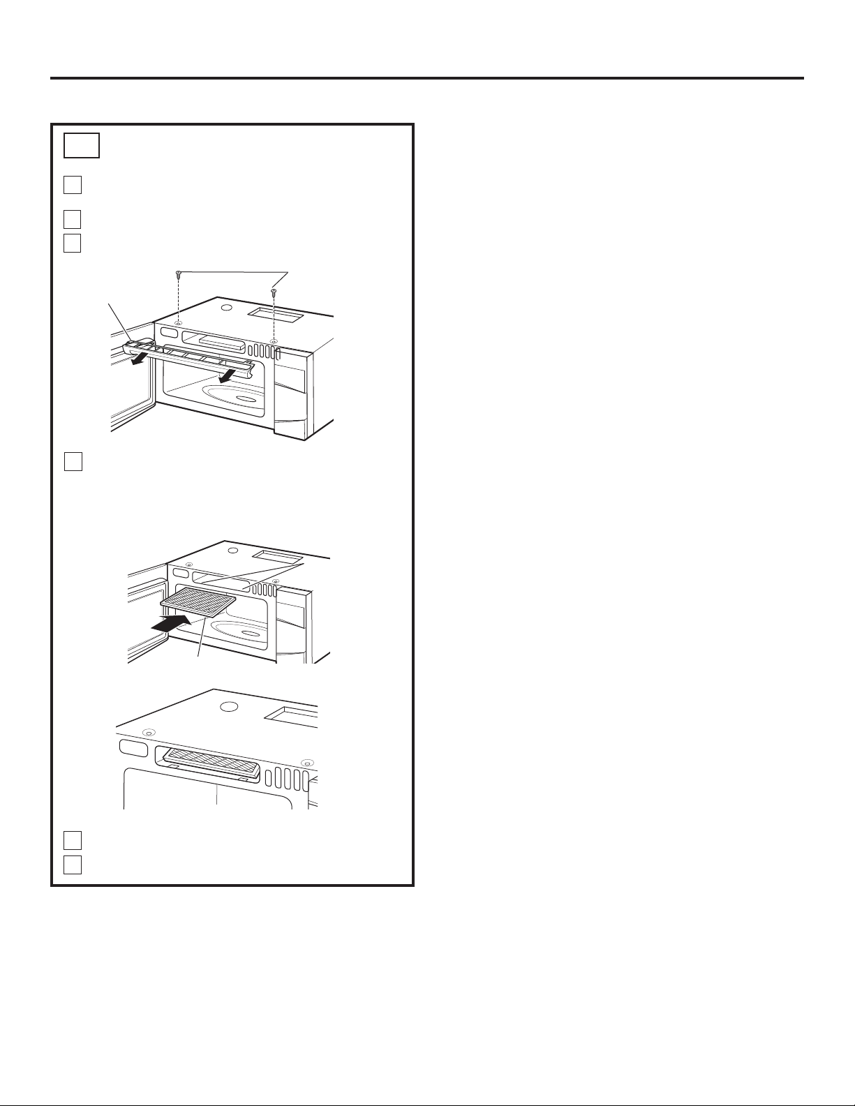
Retirez les 2 vis sur le dessus du four, juste au-dessus de
la grille d'aération, à l'aide d'un tournevis Phillips.
Ouvrez la porte.
Enlevez la grille.
Insérez le filtre dans le four comme indiqué, jusqu'à ce
qu'il soit parfaitement en place. Le filtre repose en position
inclinée, derrière les languettes inférieures avant. Lorsqu’il
est bien installé, le treillis métallique du filtre est visible de
l’avant.
2
1
INSTALLATION DU FILTRE À CHARBON
C5
46
Instructions d’installation
4
Replacez la grille et les 2 vis supérieures.
Fermez la porte et replacez la vis du côté gauche.
5
6
3
Vis
Grille
Languettes
inférieures avant
Filtre à charbon
Filtre à charbon installé

CONSERVEZ LES INSTRUCTIONS D’INSTALLATION
POUR VOTRE INSPECTEUR LOCAL.
Modèles de 120 V : Branchez le cordon d’alimentation
dans une prise de courant réservée de 15 à 20 A.
7
Lisez le Manuel de l'utilisateur.
6
Enlevez tout le matériel d’emballage du four.
2
Assurez-vous que le four a été installé conformément
aux instructions.
1
47
AVANT D'UTILISER VOTRE FOUR
INSTRUCTIONS
D’INSTALLATION
MANUEL DE
L’UTILISATEUR
Instructions d’installation
Installez le plateau tournant et son support à roues
dans le four.
3
5
Si la prise murale est du type standard à deux alvéoles,
il est très important de la faire remplacer par une prise
à trois alvéoles correctement mise à la terre, en vous
adressant à un électricien qualifié.
INSTRUCTIONS
D’INSTALLATION
Réinstallez le fusible ou réenclenchez le disjoncteur du
panneau de distribution principal.
4
Avant l'utilisation,
vérifiez la qualité de
la mise à la terre.

Imprimé en Corée
48