Loading ...
Loading ...
Loading ...
Part Number 4530588 rev 3 4/15 7
INSTALLATION
Entry Clearance
• Crated: 47” (1194mm)
• Uncrated: 32-1/2” (826mm)
Installation Clearance
NOTE: Always provide adequate clearance for maintenance
and operation.
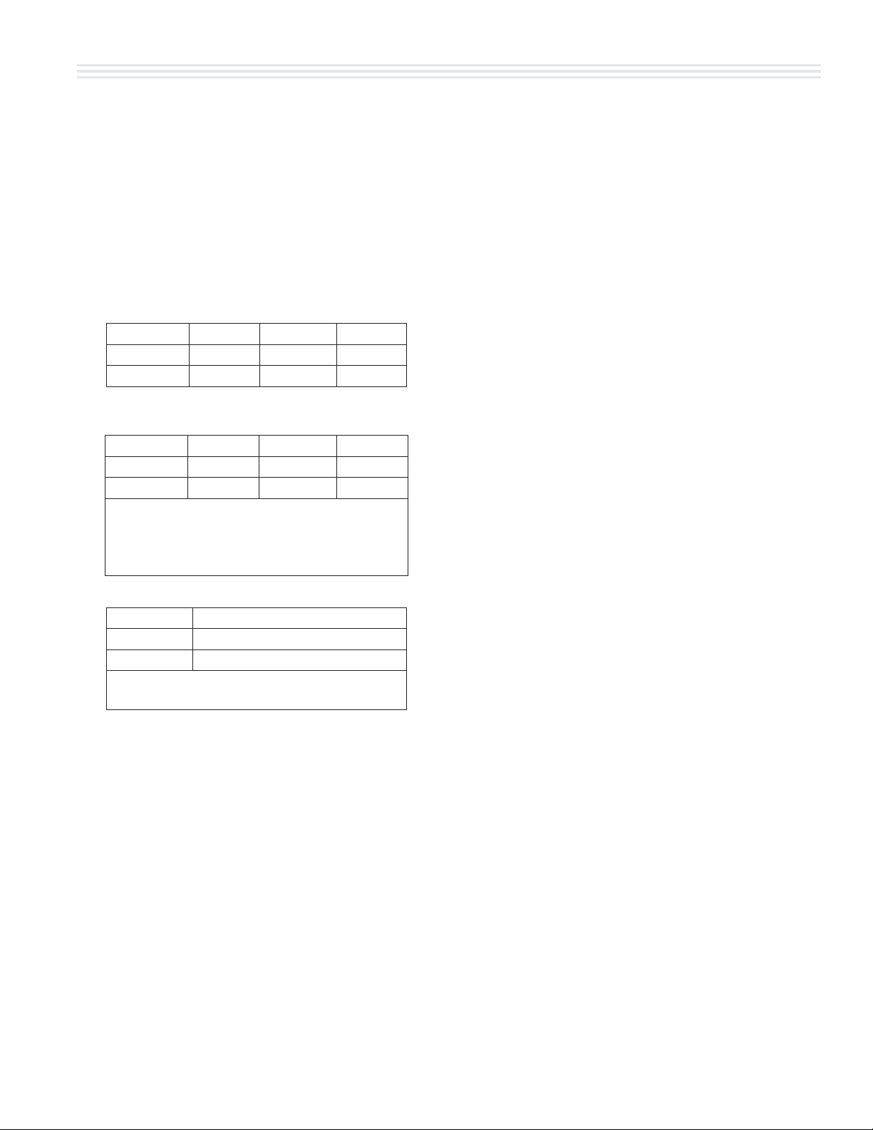
• Installation adjacent to combustible and non-
combustible wall, minimum clearance:
Left Side Control Side Rear
Single-Deck 1" (26 mm) 1" (26 mm) 3" (77 mm)
Double-Deck 1" (26 mm) 2" (51 mm) 3" (77 mm)
• Installation near high heat producing equipment,
minimum clearance:
Left Side Control Side Rear
Single-Deck 1" (26 mm) 6" (153 mm) 3" (77 mm)
Double-Deck 1" (26 mm) 6" (153 mm) 3" (77 mm)
Notice
Avoid installing ovens near equipment, such as char-
broilers or fryers, which generate high heat and high
grease laden air.
• Clearance for Service (recommendation):
Control Side, minimum
Single-Deck 12" (305 mm)
Double-Deck 12" (305 mm)
NOTE: Install units with casters in very tight
locations for ease of service.
Location
Each gas appliance shall be located with respect to building
construction and other equipment so as to permit access to
the appliance. Such access and clearance may be necessary
for servicing and cleaning.
IMPORTANT: All gas burners and pilots need su cient air
to operate and large objects should not be placed in front
of this oven, which would obstruct the air ow through the
front. Objects should not be placed on main top rear of oven
while in use. This could obstruct the venting system of the
unit’s ue products.
Installation Of Ovens
Equipped With Casters
A. For an appliance equipped with casters, the installation
shall be made with a connector that complies with the
Standard for Connectors for Movable Gas Appliances,
ANSI Z21.69 /CSA 6.16, and a quick-disconnect device
that complies with the Standard for Quick-Disconnect
Devices for Use With Gas Fuel, ANSI Z21.41 / CSA 6.9,
and adequate means must be provided to limit the
movement of the appliance without depending on
the connector and the quick-disconnect device or its
associated piping to limit the appliance movement and
the location(s) where the restraining means may be
attached to the appliance shall be speci ed.
B. The front casters of the unit are equipped with brakes
to limit the movement of the oven without depending
on the connector and any quick-disconnect device or its
associated piping to limit the appliance movement.
C. The restraint can be attached to the unit near the gas
inlet. If the restraint is disconnected, be sure to reconnect
the restraint after the oven has been returned to its
originally installed position.
Installation of Double Deck Models
A. Position insert in bottom leg opening and tap insert up
into leg until it seats at collar. Attach six inch (6”, 152mm)
legs to lower oven section. Raise unit or lay on its left side.
Place the front legs on the oven so as to line up with four
(4) attaching bolt holes. Secure leg to oven frame using
(4) 3/8-16 x 3/4 bolts and washers provided. Repeat at
rear of unit.
B. Remove lower front cover of top deck (located under
oven doors). Raise top deck into place and line up body
sides and back of the unit. Fasten the rear of the units
together, with the stacking bracket, using (6) 1/4-20
machine screws, lock washers and nuts, (provided).
C. Install the interconnecting ue parts, carefully following
the instructions contained in the stacking kit. Pay
particular attention to the type of ovens you are stacking
and be sure to follow the corresponding instructions.
Loading ...
Loading ...
Loading ...