Loading ...
Loading ...
3
www.jbl.com
English
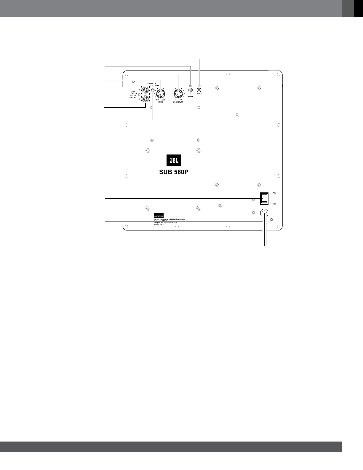
suBwooFer rear-Panel controls and connectIons
Input Mode switch: This switch determines if the input signal passes
through the subwoofer’s built-in low-pass crossover network.
• If you are connecting the subwoofer to a source device that does not
have its own crossover network (such as a stereo preamp), set the
switch in the “Normal” position. The input signal will pass through
the subwoofer’s built-in crossover network.
• If you are connecting the subwoofer to a source device that does
have its own crossover network (such as an audio/video receiver
with built-in bass management), set this switch in the “LFE” position.
The input signal will bypass the subwoofer’s built-in crossover
network.
Phase switch: This switch determines whether the subwoofer driver’s
piston-like action moves in and out in phase with the system’s other
speakers. If the subwoofer were to play out of phase with the other
speakers, the sound waves from the other speakers could partially
cancel out the sound waves from the subwoofer, reducing bass
performance and sonic impact. This phenomenon depends in part on
the placement of all the speakers relative to each other in the room.
Crossover control: This control determines the highest frequency
at which the subwoofer reproduces sounds. The higher you set
the Crossover control, the higher in frequency the subwoofer will
operate and the more its bass will “overlap” that of the system’s other
speakers. This adjustment helps achieve a smooth transition of bass
frequencies between the subwoofer and the other speakers for a variety
of different rooms and subwoofer locations. NOTE: The Crossover
control functions only when the Input Mode switch is in the
“Normal” position. When the switch is in the “LFE” position
the subwoofer’s built-in crossover and Crossover control are
bypassed.
Level control: Use this control to adjust the subwoofer’s volume.
Turn the knob clockwise to increase the volume; turn the knob
counterclockwise to decrease the volume.
Line In connectors: Connect your source device to these connectors.
• When you’re connecting the subwoofer to the preamp or subwoofer
outputs of a receiver/processor that does not have its own low-pass
crossover network, use both Line In connectors and set the Input
Mode switch in the “Normal” position.
• When you’re connecting the subwoofer to the dedicated subwoofer
output of a receiver/processor that has its own low-pass crossover
network, use either Line In connector and set the Input Mode switch
in the “LFE” position.
On/Standby indicator: This LED indicates whether the subwoofer is in
the On or Standby state:
• When the LED glows green, the subwoofer is turned on.
• When the LED glows red, the subwoofer is in the Standby mode.
• When the LED is off, the subwoofer’s Power switch is set to “Off.”
Power switch: Set this switch in the “On” position to put the
subwoofer in the Standby mode (the On/Standby LED lights red); set
this switch in the “Off” position to turn the subwoofer off.
Power cord: After you have made and verified all subwoofer
connections described in this manual, plug the power cord into
an active, unswitched electrical outlet for proper operation of the
subwoofer. DO NOT plug this cord into the accessory outlet found on
some audio components.
Level Control
Crossover Control
On/Standby
Indicator
Phase Switch
Input Mode Switch
Line In
Connectors
Power Switch
Power Cord
Loading ...
Loading ...