Loading ...
Loading ...
English
You must use both coils of a dual voice-coil woofer connected 2.
either in series or in parallel.
Most amplifiers deliver exactly the same amount of power bridged 3.
into a 4-ohm load as they do running a 2-ohm stereo load.
To design a subwoofer system that maximizes available amplier power,
keep the following rules in mind:
The total system impedance of woofers in parallel can be calculated 1.
using this formula:
Impedance =
1
w
1
+
1
w
2
+
1
w
3
...
1
where w is the nominal impedance of the woofer.
2. The total system impedance of voice coils (or woofers) in series can
be calculated using this formula:
Impedance = w
1
+ w
2
+ w
3
...
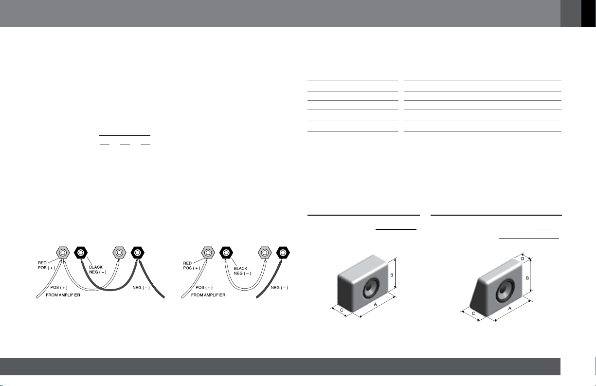
The diagrams below show parallel and series speaker connections.
SUGGESTED ENCLOSURES
Internal Volume Internal Volume Qty. Duct(s) Diameter x Length
0.78 ft
3
(22L) 1.13 ft
3
(32L) 1 2.95 in x 9.84 in (7.5cm x 25cm)
0.78 ft
3
(22L) 1.13 ft
3
(32L) 1 2.95 in x 9.84 in (7.5cm x 25cm)
0.95 ft
3
(27L) 1.7 ft
3
(48L) 1 3.94 in x 8.66 in (10cm x 22cm)
0.95 ft
3
(27L) 1.7 ft
3
(48L) 1 3.94 in x 8.66 in (10cm x 22cm)
1.27 ft
3
(36L) 2.12 ft
3
(60L) 2 3.94 in x 14.96 in (10cm x 38cm)
– The suggested enclosure volumes are related to only one speaker, including woofer and duct(s)
displaced volume.
– For enclosures with more than one speaker, it is necessary to multiply the suggested volume and
duct(s) by the quantity of speakers.
ENCLOSURES INTERNAL VOLUME
CALCULATION INSTRUCTIONS
Internal Volume =
A x B x C
1000
A x B x
(
C + D
)
1000
2
Internal Volume =
– A, B and C are internal dimensions.
Loading ...
Loading ...
Loading ...