K011A-1V190128
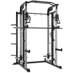
CEM-10 CA Cable
Machine (COVER,
ALUMINUM GRIP)
OWNER’S MANUAL
IMPORTANT !
Please read all instructions carefully before using this product.
Retain this manual for future reference.
The specifications of this product may vary slightly from the illustrations and are subject to
change without notice.

- 1 -
SAFETY INFORMATION
NOTE THE FOLLOWING PRECAUTIONS BEFORE ASSEMBLING AND OPERATING THE
MACHINE. UNDERSTANDING EACH AND EVERY WARNING TO THE FULLEST IS
IMPORTANT.
KEEP CHILDREN AWAY from strength equipment. Parent or others supervising children
must provide close supervision of children if the equipment is used in the presence of
children.
IT IS RECOMMENDED THAT ALL USERS OF THIS EXERCISE EQUIPMENT BE INFORMED OF
THE FOLLOWING INFORMATION PRIOR TO USE.
-ACCESS CONTROL
Recommends that all fitness equipment be used in a supervised area. It is recommended that
the equipment be located in an access-controlled area. Control is the responsibility of the
facility owner.
-INSTALLATION
SECURING EQUIPMENT - recommends that all equipment be secured to a solid, level surface
to stabilize and eliminate rocking or tipping over.
-PROPER USAGE
1. Do not use any equipment in any way other than as designed or intended by the manufacturer.
It is imperative that the equipment is used properly to avoid injury.
2. Injuries may result if exercising improperly or excessively. It is recommended that all individuals
consult a physician prior to commencing an exercise program. If at any time during exercise you
feel faint, dizzy or experience pain, STOP EXERCIZING and consult your physician.
3. Keep body parts (hands, feet, hair, etc.), clothing and jewelry away from moving parts to avoid
injury.
INSPECTION
1. DO NOT use or permit use of any equipment that is damaged and or has worn or broken parts. For
all equipment use only replacement parts supplied by the manufacturer.
2. Cables and Belts pose an extreme liability if used when frayed. Always replace any cable at first sign
of wear.
3. Routinely inspect all accessory clips that join attachments to the cables and replace at the first sign
of wear.
4. MAINTAIN LABELS AND NAMEPLATES - Do not remove labels for any reason. They contain important
information.
5. EQUIPMENT MAINTENANCE - Preventative maintenance is the key to smooth operating equipment
as well as keeping your liability to a minimum. Equipment needs to be inspected at regular intervals.
6. Ensure that any person(s) making adjustments or performing maintenance or repair of any kind is
qualified to do so.
7. Before any use, examine all accessories approved for use with the equipment for damage or wear.
8. DO NOT ATTEMPT TO USE OR REPAIR ANY ACCESSORY APPROVED FOR USE WITH THE EQUIPMENT
WHICH APPEARS TO BE DAMAGED OR WORN.

- 2 -
OPERATING WARNINGS
1. It is the purchaser's sole responsibility to properly understand all the SAFTY INFORMATION.
2. Keep children away from strength equipment. Parent or others supervising children must
provide close supervision of children if the equipment is used in the presence of children.
3. Do not allow users to wear loose fitting clothing or jewelry while using equipment. It is also
recommended to have user's secure long hair back and up to avoid contact with moving parts.
4. All bystanders must stay clear of all users, moving parts and attached accessories and
components while machine is in operation.
PREPARATION
Thank you for purchasing this equipment. This machine is part of our line of quality strength
training machines, which lets you target specific muscle groups to achieve better muscle
tone and overall body conditioning. To maximize your use of the equipment please study this
Owner’s Manual thoroughly.
INSTALLATION Requirements
Follow these installation requirements when assembling:
Set up the machine on a solid, flat surface. A smooth, flat surface under the machine helps
keep it level. A level machine has fewer malfunctions.
Provide ample space around the machine. Open space around the machine allows for easier
access.
Insert all bolts in the same direction. For aesthetic purposes, insert all bolts in the same
direction unless specified (in text or illustrations) to do otherwise.
Leave room for adjustments. Tighten fasteners such as bolts, nuts, and screws so the unit is
stable, but leave room for adjustments. Do not fully tighten fasteners until instructed in the
assembly steps to do so.
ASSEMBLY Tips
Read all “Notes” on each page before beginning each step.
While you may be able to assemble the machine using the illustrations only, important safety
notes and other tips are included in the text.
Some pieces may have extra holes that you will not use. Use only those holes indicated in
the instructions and illustrations.
NOTE: With so many assembled parts, proper alignment and adjustment is critical. While
tightening the nuts and bolts, be sure to leave room for adjustments.
NOTE: The bottles that are marked “Poison” is your touch up paint. Keep away from
children.
CAUTION: Obtain assistance! If you feel like you can’t assemble the machine by yourself then
do not attempt to do so as this could result in injury. Review the installation requirements
before proceeding with the following steps.
- 3 -
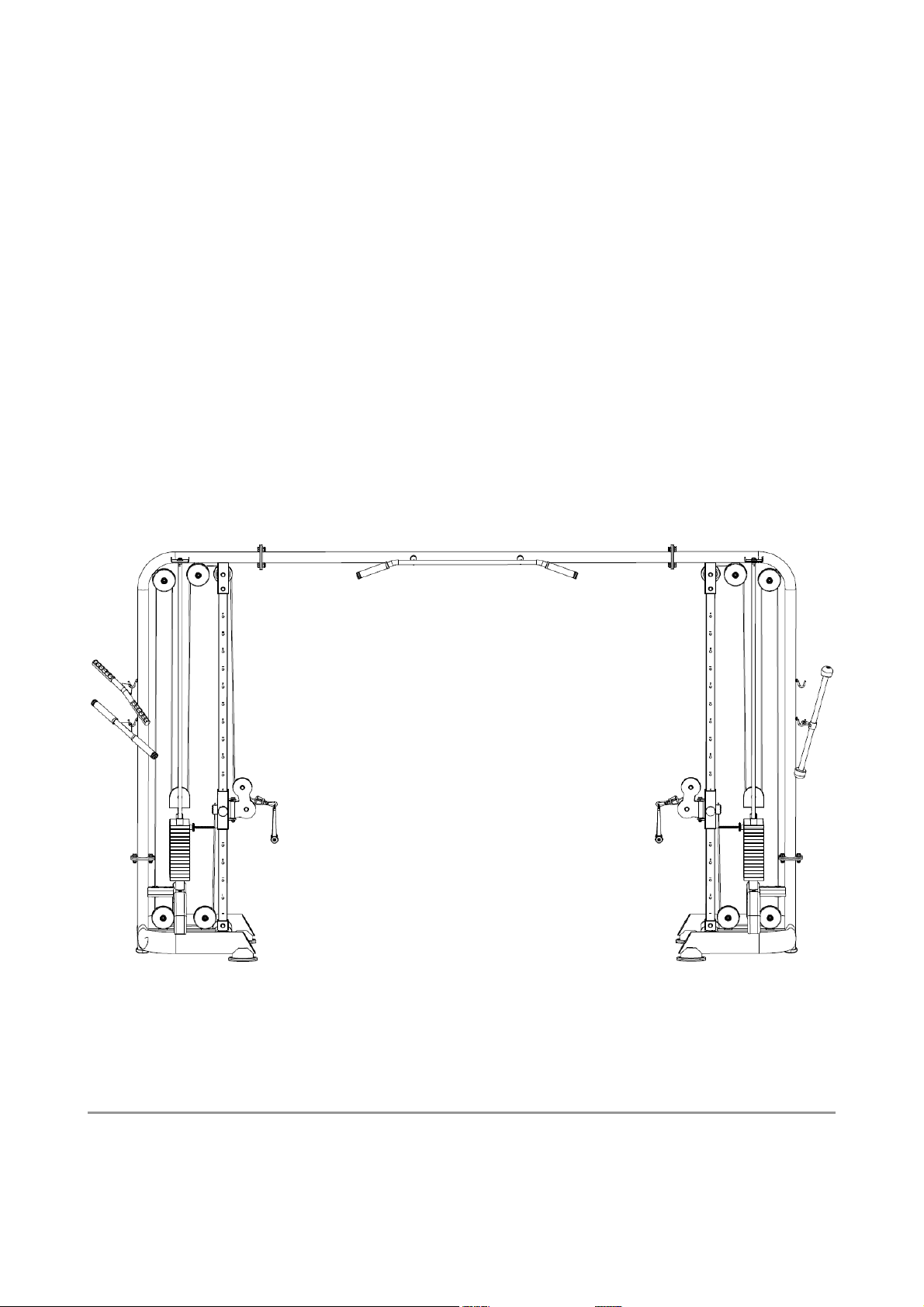
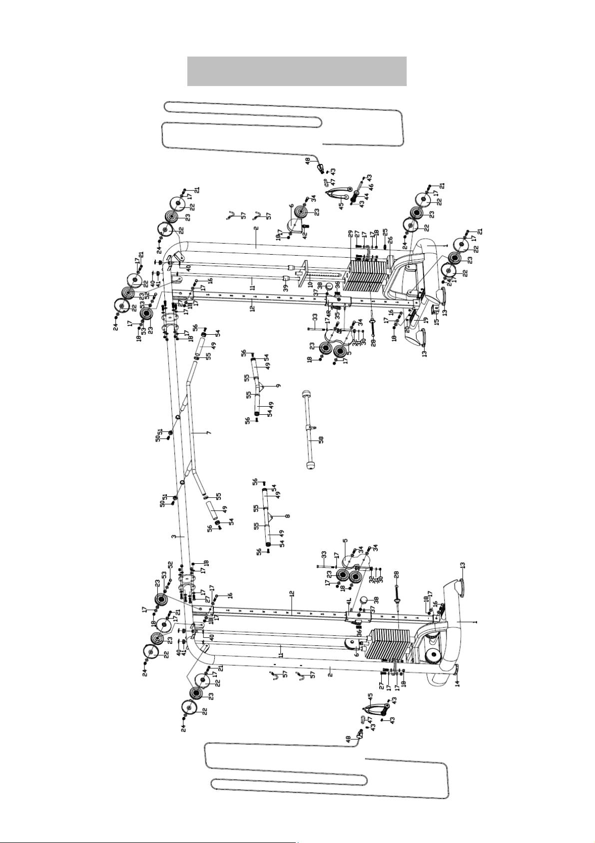
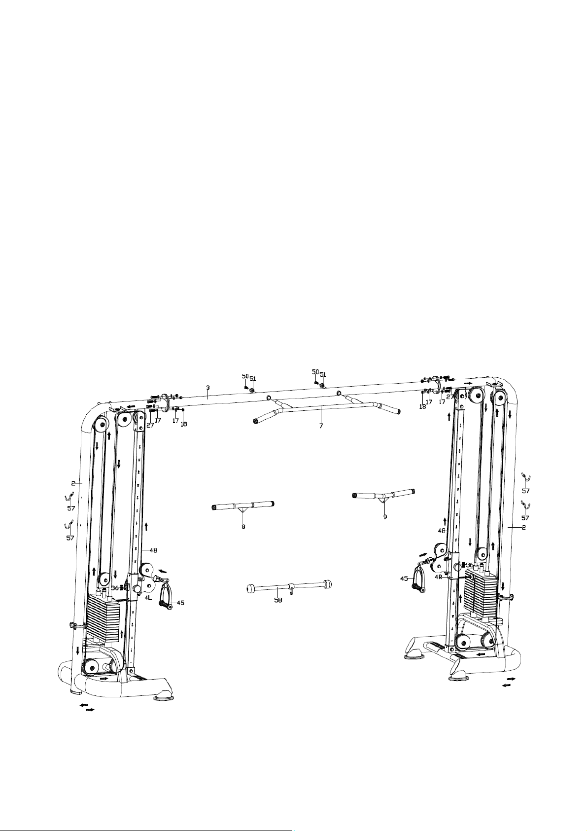
EXPLODED DIAGRAM

- 4 -
PARTS LIST
NO. DESCRIPTION QTY NO. DESCRIPTION QTY
1 Stabilizer 2 30 Nylon nut M10 2
2 Upright frame 2 31 Flat washerD10×D20×2 2
3
Top cross frame
1
32
Oilite bushing
4
4L/R
Slide guide joint
1/1
33
Hex pivot bolt M10
×
132
2
5
Double pulley block
2
34
Hex bolt M12
×
48
6
6
U-shaped pulley block
2
35
Grip
2
7 Chin-up bar 1 36 Allen bolt M8×16 6
8 Low lat bar 1 37 Hex nut M16×1.5 2
9 Curl bar 1 38 Pop-pin knob
2
10
Selector rod
1
39
Nylon sleeve
4
11
Guide rod
4
40
E-shaped washer Φ15
8
12
Slide guide post
2
41
Plug
4
13 Rubber feet 4 42 Hex nut M16 2
14 Oval feet 2 43 Allen bolt M8×20 6
15 Plastic bushing 8 44 Handle grip 2
16 Hex bolt M12×78 4 45 Handle 2
17
Flat washer D13
×
2.5
×
Φ24
76
46
Handle grip shaft Φ16
×
140
2
18
Nylon nut M12
28
47
Hoist hook
2
19
Foot rest
4
48
Steel cable
2
20 Cross flat screw M4×12 12 49 Foam grip 6
21 Allen cylindrical bolt M12×60 8 50 Allen cylindrical bolt M12×30 2
22 Pulley cover 16 51 End cap washer 2
23
Aluminum pulley
16
52
Hex bolt M12
×
85
2
24
Acorn nut M12
8
53
Spacer
4
25
Plug
4
54
Aluminum collar
6
26
Rubber bumper
4
55
Handle Ring
6
27 Hex bolt M12×35 16 56 Allen flat bolt M10×30 6
28 Weight stack pin 2 57 Pothook 4
29 Weight stack 30 58 Lat grip rope 1
NOTE:
Most of the listed hardware has been packaged separately, but some of them have been
preinstalled in the identified assembly parts. In these instances, simply remove and
reinstall the hardware as assembly is required.
- 5 -
ASSEMBLY INSTRUCTION
NOTE: It is well suggested that two or more people to assemble this machine to avoid
any possible injury.
Remove all the security tape and wrapping before the installation.
Please refer the individual steps for the installation and pay attention to the preinstalled
hardware.
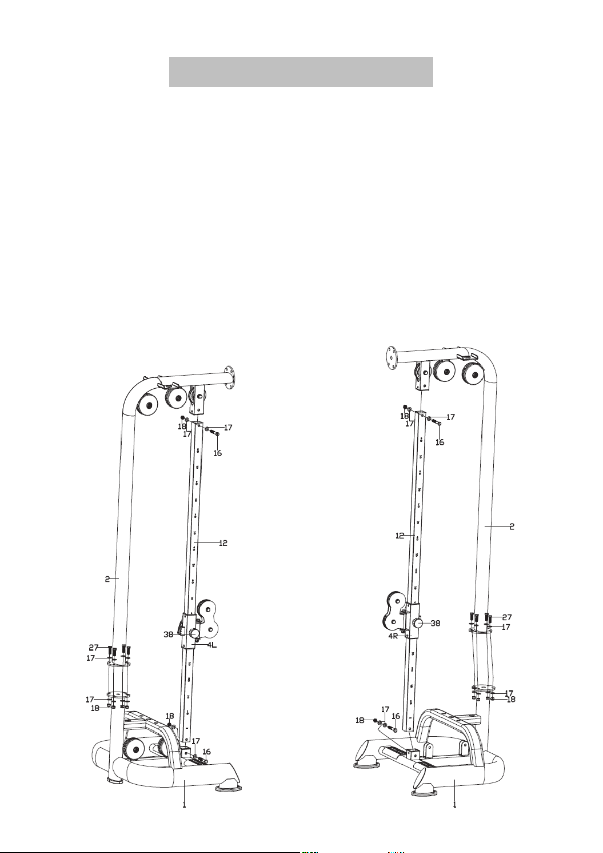
STEP 1
A: Insert the Slide Guide Joint (4L/R) to the Slide Guide Posts (12) and fasten with the Pop-pin
knob (38), then insert the Slide Guide Posts (12) to the Stabilizers (1) & Upright Frames (2),
secure with the Hex bolts (16), Flat washers (17) & Nylon nuts (18) as shown.
B: Fix the Upright Frames (2) onto the Stabilizers (1) with the Hex bolts (27), Flat washers (17) &
Nylon nuts (18).
- 6 -
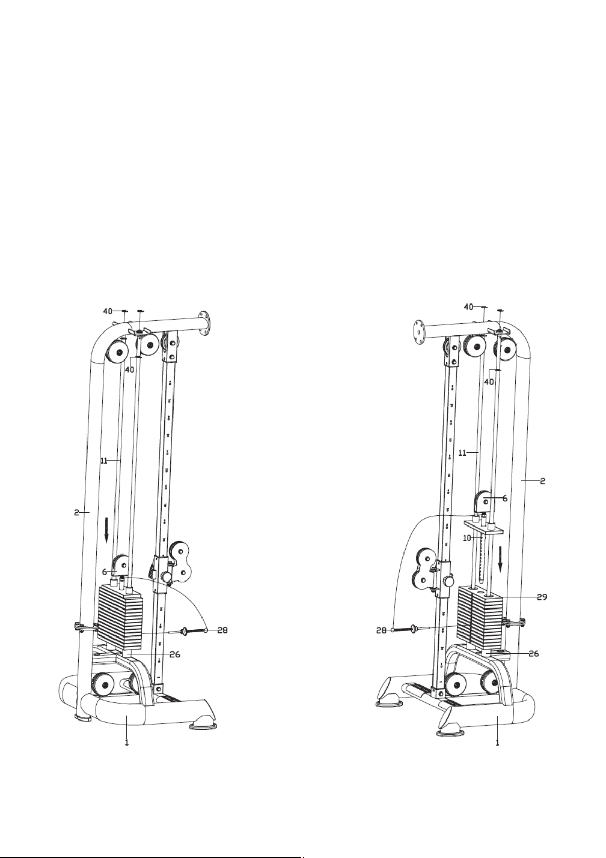
STEP 2
A. Insert the Guide Rods (11) to the Stabilizers (1) (Note: Insert and push it to the bottom for
easy assembling), and then insert the Rubber Bumpers (26), Weight Stacks (29) & the
Selector Rod Joint (10) to the Guide Rods (11), finally fix the top end of Guide Rods (11) to
the Upright Frames (2) with E-shaped washers (40) as shown.
B. Sleeve the Wire end of Weight Stack Pin (28) to the U-shaped Pulley Block (6), then insert
the Weight Stack Pin (28) to the hole of the Weight Stack (29) & Selector Rod (10)
accordingly, finally thread the U-shaped Pulley Block (6) into the Selector Rod (10).
- 7 -
STEP 3
A: Fix the Top Cross Frame (3) to the Upright Frames (2) with the Hex bolts (27), Flat washers
(17) & Nylon nuts (18), then fix the Chin-up Bar (7) to the Top Cross Frame (3) with the Allen
cylindrical bolts (50) & End cap washers (51).
B: Connect the Steel Cable (48) to the Handle (45), feed the Steel Cable (48) passing by the
pulleys as direction shown, then pull to tight the Steel Cable (48) and fix it to the Slide Guide
Joint (4L/R) with the Allen bolts (36) as shown.
C: The Low Lat Bar (8), Curl Bar (9) and Lat Grip Rope (58) are options to replace the Handle (45)
for different workouts.
NOTE: Check whether the equipment is shaken unsteadily after installation. If it appears,
force the both side Stabilizers (1) to the outside or push it to the inside slightly to adjust
the equipment until it is stable.
- 8 -
WARM-UP and COOL-DOWN
A successful exercise program consists of a Warm-Up, Exercise, and a Cool-Down. Do the
entire program at least two and preferably three times a week, resting for a day between
workouts. After several months, you can increase your workouts to four or five times per
week.
WARM-UP
The purpose of warming up is to prepare your body for exercise and to minimize injuries.
Warm up for two to five minutes before strength-training or aerobic exercising. Perform
activities that raise your heart rate and warm the working muscles. Activities may include
brisk walking, jogging, jumping jacks, jump rope, and running in place.
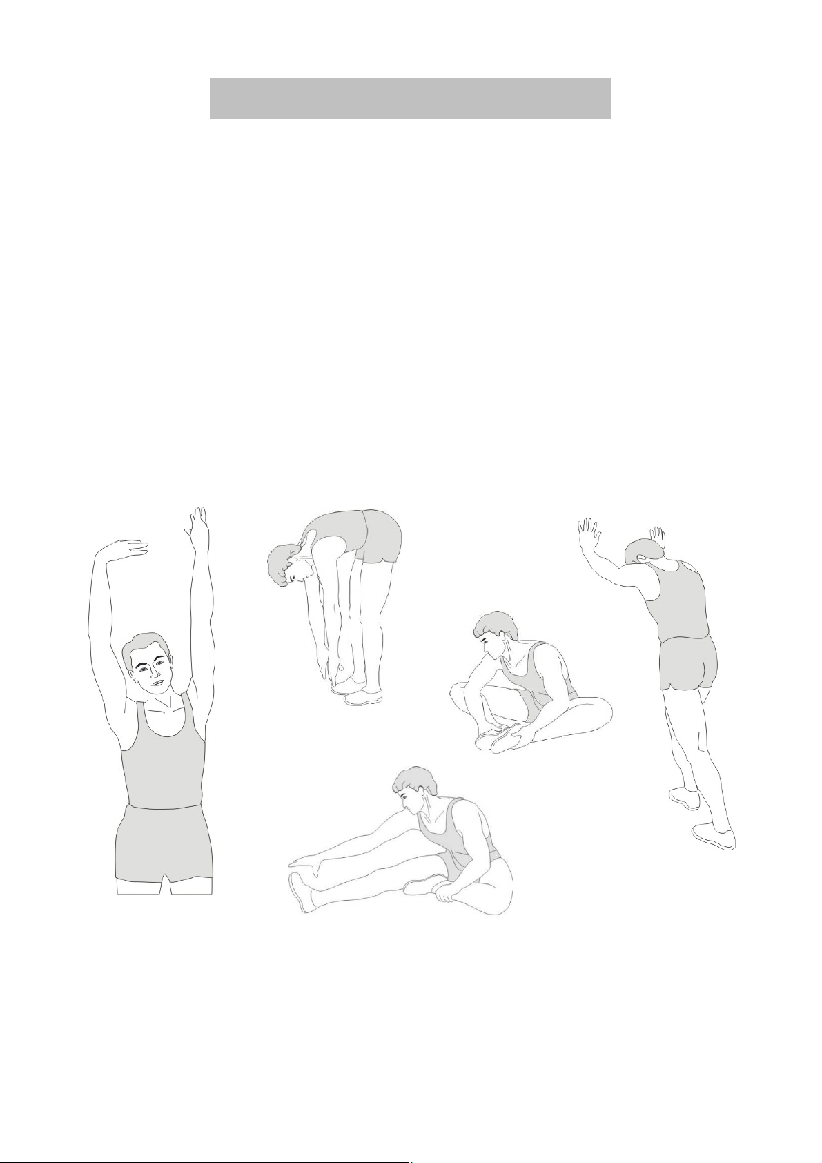
STRETCHING
Stretching while your muscles are warm after a proper warm-up and again after your
strength or aerobic training session is very important. Muscles stretch more easily at these
times because of their elevated temperature, which greatly reduces the risk of injury.
Stretches should be held for 15 to 30 seconds. DO NOT BOUNCE.
REMEMBER Always To Check with your physician before starting any exercise program.
COOL-DOWN
The purpose of cooling down is to return the body to its normal or near normal, resting
state at the end of each exercise session. A proper cool-down slowly lowers your heart rate
and allows blood to return to the heart.
Calf-Achilles Stretch
Inner Thigh Stretch
Toe Touch
Side Stretch
Hamstring Stretch