Version 09/12 - Page 1
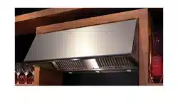
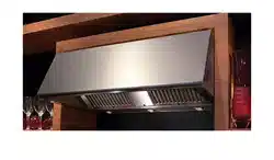
MAGNUM
Under Cabinet Rangehood
READ AND SAVE THESE INSTRUCTIONS
READ THESE INSTRUCTIONS BEFORE YOU START INSTALLING THIS RANGEHOOD
WARNING: - TO REDUCE THE RISK OF A RANGE TOP GREASE FIRE: a) Never leave surface units unattended at high settings. Boilovers cause
smoking and greasy spillovers that may ignite. Heat oils slowly on low or medium setting. b) Always turn hood ON when cooking at high heat
or when ambeing food (i.e. Crepes Suzette, Cherries Jubilee, Peppercorn Beef Flambé). c) Clean ventilating fans frequently. Grease should not
be allowed to accumulate on fan or lter. d) Use proper pan size. Always use cookware appropriate for the size of the surface element.
WARNING: - TO REDUCE THE RISK OF INJURY TO PERSONS IN THE EVENT OF A RANGE TOP GREASE FIRE, OBSERVE THE FOLLOWING *: SMOTHER
FLAMES with a close-tting lid, cookie sheet, or metal tray, then turn off the burner. BE CAREFUL TO PREVENT BURNS. If the ames do not go out
immediately EVACUATE AND CALL THE FIRE DEPARTMENT. NEVER PICK UP A FLAMING PAN - You may be burned. DO NOT USE WATER, including
wet dishcloths or towels - a violent steam explosion will result. Use an extinguisher ONLY if: 1. You know you have a Class ABC extinguisher, and
you already know how to operate it. 2. The re is small and contained in the area where it started. 3. The re department is being called. 4. You
can ght the re with your back to an exit. * Based on "Kitchen Firesafety Tips" published by NFPA
LISEZ BIEN CETTE FICHE AVANT D'INSTALLER LA HOTTE
AVERTISSEMENT - POUR MINIMISER LE RISQUE D’UN FEU DE GRAISSE SUR LA TABLE DE CUISSON : a) Ne jamais laisser un élément de la table
de cuisson fonctionner sans surveillance à la puissance de chauffage maximale; un renversement/débordement de matière graisseuse pourrait
provoquer une inammation et le génération de fumée. Utiliser toujours une puissance de chauffage moyenne ou basse pour le chauffage d’huile.
b) Veiller à toujours faire fonctionner le ventilateur de la hotte lors d’une cuisson avec une puissance de chauffage élevée ou lors de la cuisson
d’un mets à amber (i.e. Crepes Suzette, Cherries Jubilee, Peppercorn Beef Flambé). c) Nettoyer fréquemment les ventilateurs d’extraction. Veiller
à ne pas laisser de la graisse s’accumuler sur les surfaces du ventilateur ou des ltres. d) Utiliser toujours un ustensile de taille appropriée.
Utiliser toujours un ustensile de taille adapté à la taille de l’élément chauffant.
AVERTISSEMENT: - POUR PRÉVENIR LES BLESSURES EN CAS DE FEU SUIVRE LES RECOMMANDATIONS SUIVANTES: ÉTOUFFEZ LE FEU avec un
couvercle métallique et fermez le brûleur. Si le feu ne s'éteint pas tout de suite, QUITTEZ LES LIEUX ET APPELEZ LES POMPIERS. NE TOUCHEZ
JAMAIS UNE CASSEROLE EN FLAMMES. N'UTILISEZ JAMAIS DE L'EAU ou un torchon mouillé pour éteindre le feu - ce qui pourrait causer une
explosion de vapeur. N'utilisez un extincteur que si: 1. Vous avez un modèle ABC et vous connaissez bien son mode d'emploi. 2. Le feu est petit
et peu répandu. 3. Les pompiers sont déjà prévenus. 4. Vous avez une sortie derrière vous.
Version 09/12 - Page 2
VENTING REQUIREMENTS
Flexible ductwork is not recommended. Flexible ductwork
creates back pressure and air turbulence that greatly
reduces performance.
WARNING - To Reduce The Risk Of Fire, Use Only Metal Ductwork.
WARNING - TO REDUCE THE RISK OF FIRE OR ELECTRIC SHOCK, do
not use this fan with any solid-state speed control device.
WARNING - TO REDUCE THE RISK OF FIRE, ELECTRICAL SHOCK, OR
INJURY TO PERSONS, OBSERVE THE FOLLOWING: Use this unit only
in the manner intended by the manufacturer. If you have any ques-
tions, contact the manufacturer.
Before servicing or cleaning unit, switch power off at service panel
and lock the service disconnecting means to prevent power from
being switched on accidentally. When the service disconnecting
means cannot be locked, securely fasten a prominent warning
device, such as a tag, to the service panel.
CAUTION: For General Ventilating Use Only. Do Not Use To Exhaust
Hazardous or Explosive Materials and Vapors.
WARNING - TO REDUCE THE RISK OF FIRE, ELECTRICAL SHOCK,
OR INJURY TO PERSONS, OBSERVE THE FOLLOWING: Installation
Work And Electrical Wiring Must Be Done By Qualied Person(s)
In Accordance With All Applicable Codes And Standards, Including
Fire-Rated Construction.
Sufcient air is needed for proper combustion and exhausting of
gases through the ue (chimney) of fuel burning equipment to prevent
backdrafting. Follow the heating equipment manufacturer's guideline
and safety standards such as those published by the National Fire
Protection Association (NFPA), and the American Society for Heat-
ing, Refrigeration and Air Conditioning Engineers (ASHRAE), and the
local code authorities.
When cutting or drilling into wall or ceiling, do not damage electrical
wiring and other hidden utilities.
Ducted fans must always be vented to the outdoors.
WARNING
WARNING
ELECTRICAL REQUIREMENTS
-
For residential use only.
!
!
Cold Weather installations
additional back draft damper should be installed to minimize
backward cold air ow and a nonmetallic thermal break should
be installed to minimize conduction of outside temperatures
as part of the vent system. The damper should be on the cold
air side of the thermal break. The break should be as close as
possible to where the vent system enters the heated portion
of the house.
CAUTION - To reduce risk of re and to properly exhaust
air, be sure to duct air outside – Do not vent exhaust air into
spaces within walls or ceilings or into attics, crawl spaces,
or garages.
RÈGLEMENTS D'ÉVACUATION
Utilisez un tuyau d'évacuation rigide lorsque possible.
Un tuyau exible égale deux fois plus qu'un tuyau rigide,
ce qui réduit la puissance d'évacuation.
AVERTISSEMENT - Pour Ne Pas Risquer Un Feu, Utilisez Seulement
Les Matériaux Métalliques.
AVERTISSEMENT - POUR RÉDUIRE LE RISQUE D'INCENDIE OU DE CHOC
ELECTRIQUE, ne pas utiliser ce ventilateur en conjonction avec un
dispositif de réglage de vitesse à semi-conducteurs.
AVERTISSEMENT – POUR MINIMISER LES RISQUES D’INCENDIE,
CHOC ÉLECTRIQUE OU DOMMAGES CORPORELS, OBSERVER LES
PRESCRIPTIONS SUIVANTES: Suivez les recommandations du fabricant
et entre en communication avec lui pour toute information.
Fermez le courant avant tout entretien et veillez a ce qu'il reste fermé.
Si on ne peut pas verrouiller le panneaux du service électrique,
afchez un avis de danger sur la porte.
AVIS: Pour L'évacuation Générale - Veillez à Ne Pas Evacuer Des
Matériaux Ou Vapeurs Explosif.
AVERTISSEMENT – POUR MINIMISER LES RISQUES D’INCENDIE,
CHOC ÉLECTRIQUE OU DOMMAGES CORPORELS, OBSERVER LES
PRESCRIPTIONS SUIVANTES: L'installation Et Le Raccordement
Electrique Doivent Se Faire Par Un Technicien Qualié Selon Tous
Les Codes Municipaux.
An d'obtenir un rendement maximal en ce qui a trait à la combustion
ainsi qu'à l'évacuation des gaz par la conduite de cheminée, une
bonne aération est nécessaire pour tous les appareils à combustion.
Suivez les conseils et mesures de sécurité du fournisseur tels que
ceux publiés par l'Association Nationale de la Sauvegarde contre
l'Incendie et l'Association Américaine d'Ingénieurs de Chauffage,
Frigorifaction et Air Climatisé ainsi que les codes municipaux.
En perçant un mur veillez à ne pas perforer un autre l électrique.
Une ventilateur à évacuation extérieure doit être raccordée à
l'extérieur.
AVERTISSEMENT
FICHE TECHNIQUE ÉLECTRIQUE
AVERTISSEMENT
Uniquement pour usage menager.
!
!
Installations pour régions à climat froid
On devrait installer un clapet antireux additionnel pour minimiser le reux
d'air froid, et incorporer un élément non métallique d'isolation thermique
pour minimiser la conduction de chaleur par l'intermédiaire du conduit
d'évacuation, de l'intérieur de la maison à l'extérieur. Le clapet anti-
reux doit être placé du côté air froid par rapport à l'élément d'isolation
thermique. L'isolant thermique doit être aussi proche que possible de
l'endroit où le système d'évacuation s'introduit dans la partie
chauffée de la maison.

TOOLS NEEDED FOR INSTALLATION
PARTS SUPPLIED FOR INSTALLATION
PARTS NEEDED FOR INSTALLATION
OPTIONAL ACCESSORIES AVAILABLE
Charcoal Filter Kit
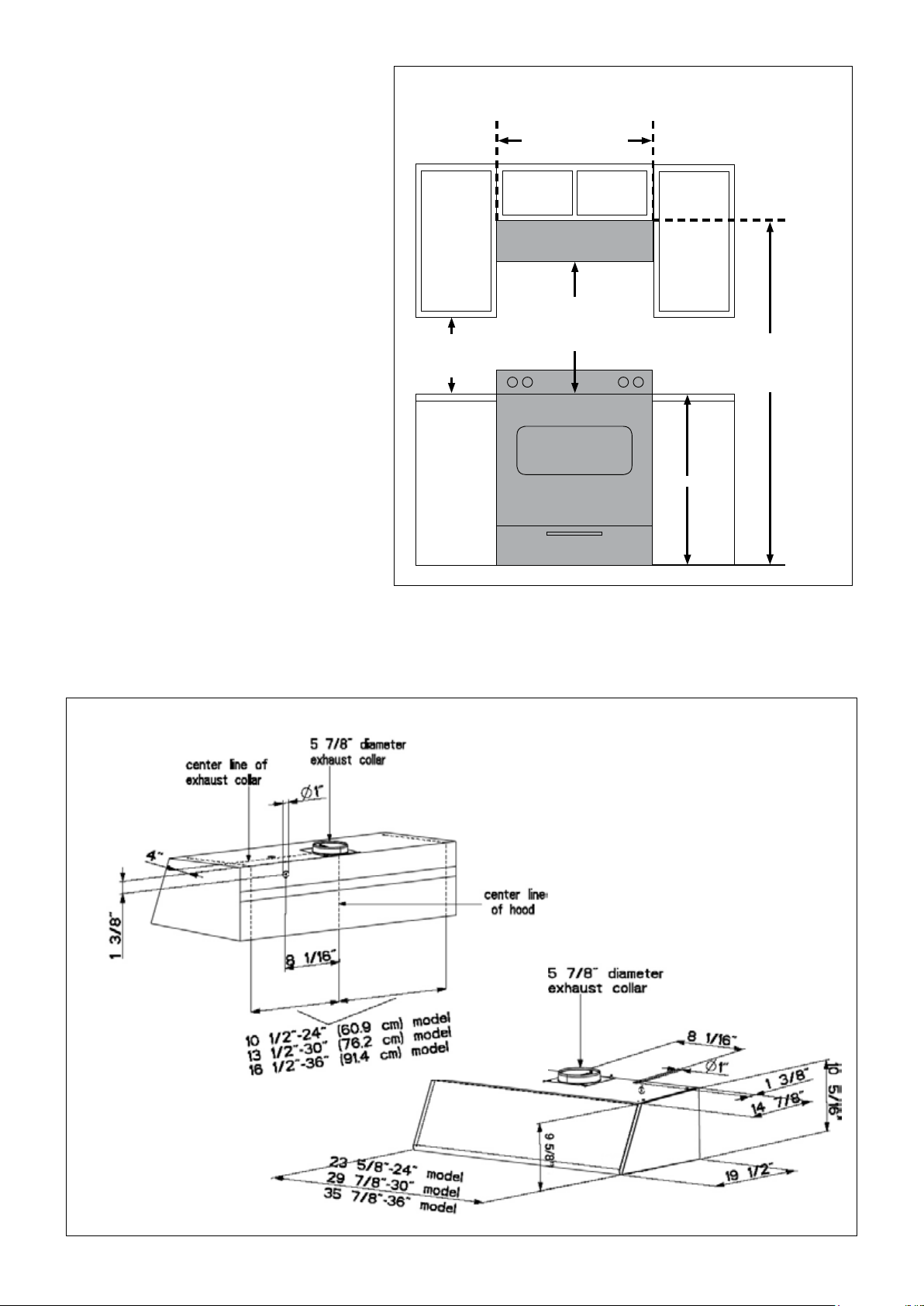
24” minimum
30” suggested maximum
bottom of hood to cooking surface
18” minimum
clearance upper
cabinet to
countertop
36”
70 5/16” minimum
76
5/16” maximum
to bottom of cabinet frame
24” or 30” or 36”
cabinet opening width
INSTALLATION CLEARANCES
• Recirculating Kit (4" tall recirculation grill + charcoal lter)
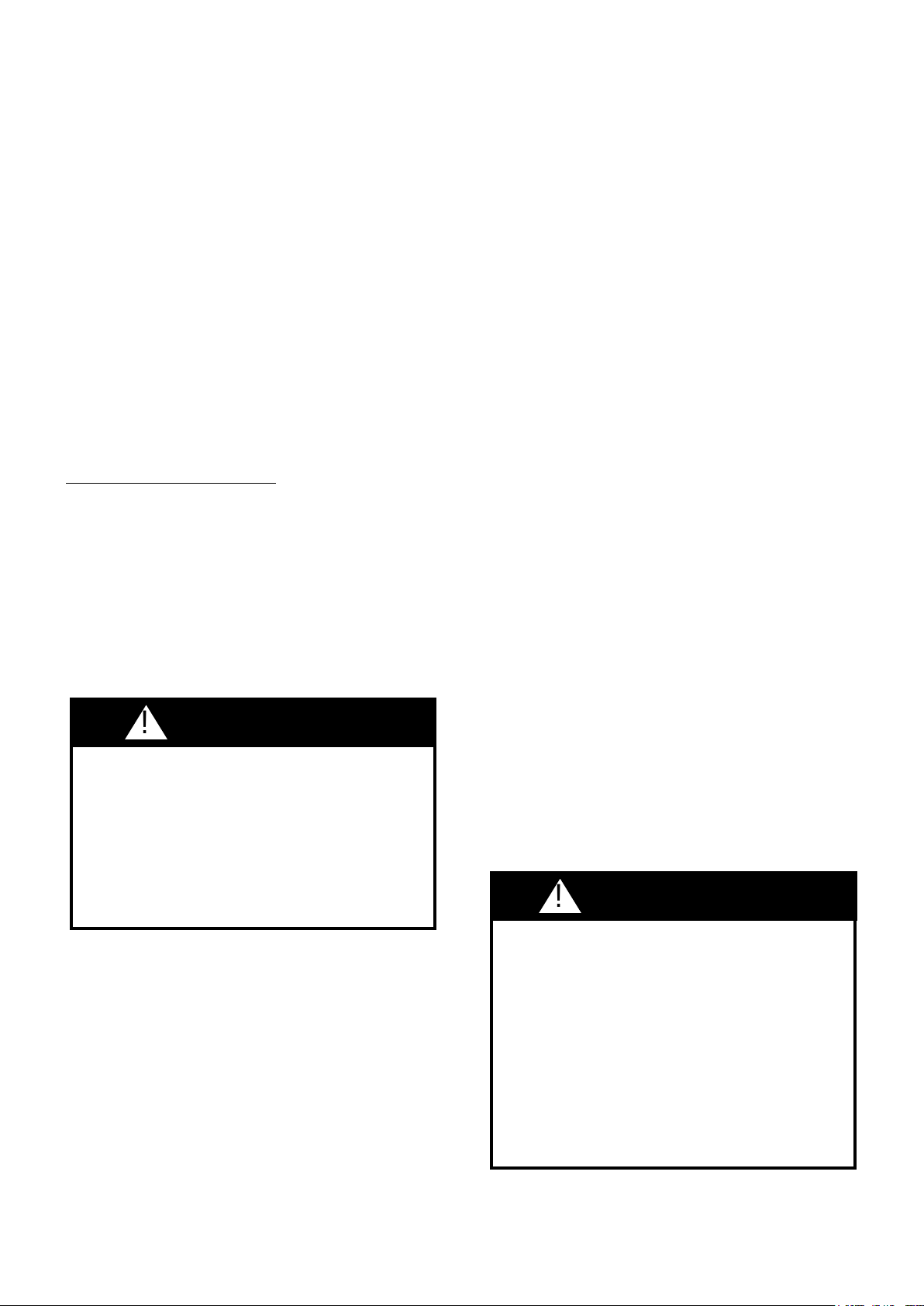
PRODUCT DIMENSIONS
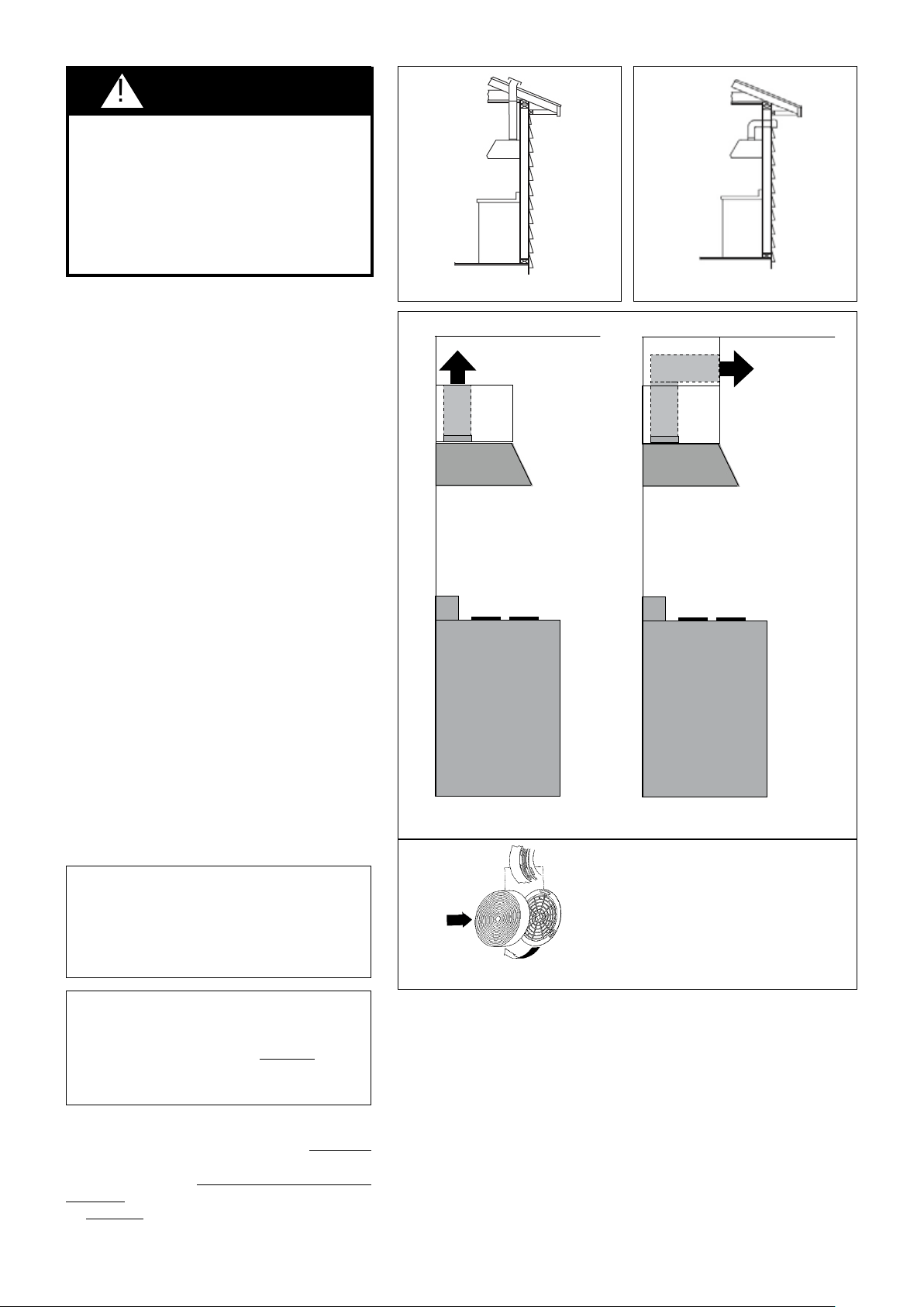
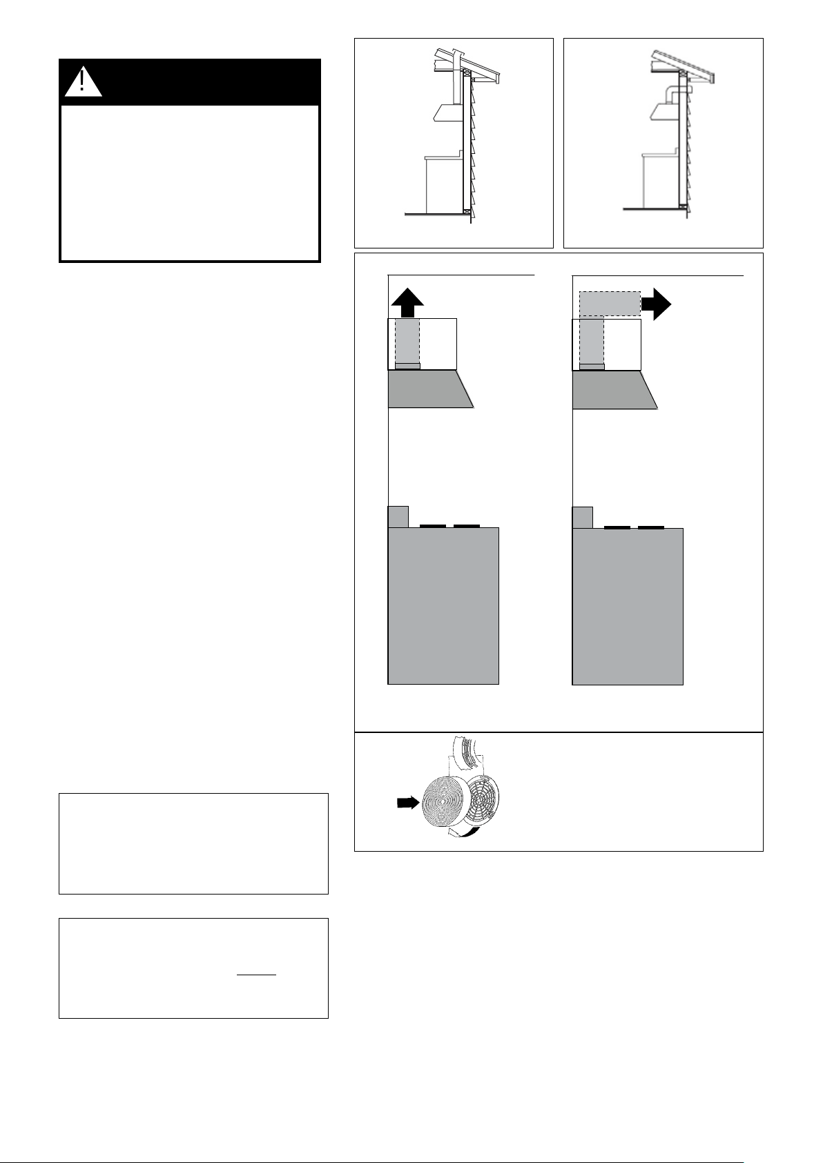
For best results, use no more than three 90°
elbows. Make sure that there is a minimum
of 24" of straight duct between elbows if more
than one is used. Do not install two elbows
together. If you must elbow right away, do it
as far away from the hood's exhaust opening
as possible.
FIGURE 5
FIGURE 4
CALCULATE THE DUCTRUN LENGTH
To ensure that the blower performs to its highest
possible capacity, duct work should be as short and
straight as possilbe.
For satisfactory performance the duct run should
not exceed 50 equivalent feet if ducted using the
required minimum 6" round duct.
in FIGURE 4
FIGURE 5
PLAN THE DUCTWORK
FIGURES 1 and 2
FIGURE
3
WARNING!
FIGURE 1 FIGURE 2
ceiling
enclosed soffit
side view
rangehood
cooking surface
upper
cabinet
ceiling
open space
side view
rangehood
cooking surface
upper
cabinet
FIGURE 3A FIGURE 3B
FIGURE 3C
WARNING
!
RECIRCULATING INSTALLATIONS
There are 2 ways to recirculate the Magnum :
(sold seperately)
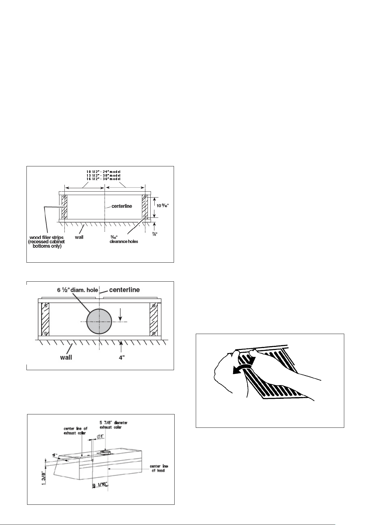
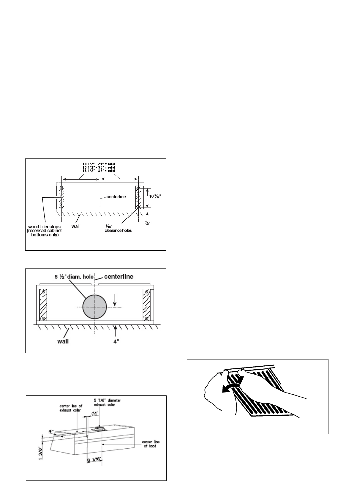
PREPARE THE CABINET
1.
2.
3.
4.
5.
FIGURE 4
6
7.
FIGURE 5
FIGURE 6
8. USING TWO HANDS
9.
10. -
-
INSTALL THE RANGEHOOD
1.
2.
3.
4.
5.
6.
(as in FIGURE 7)-
FIGURE 7
7.
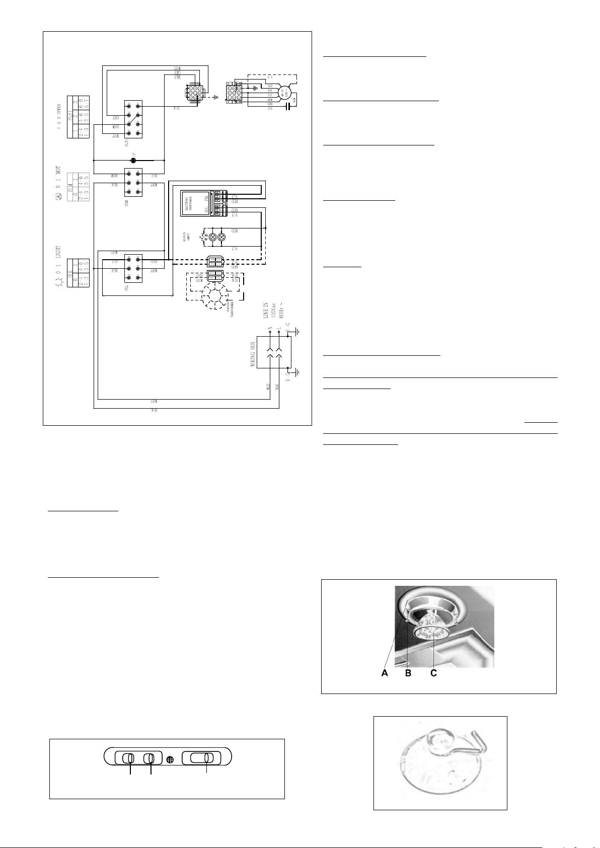
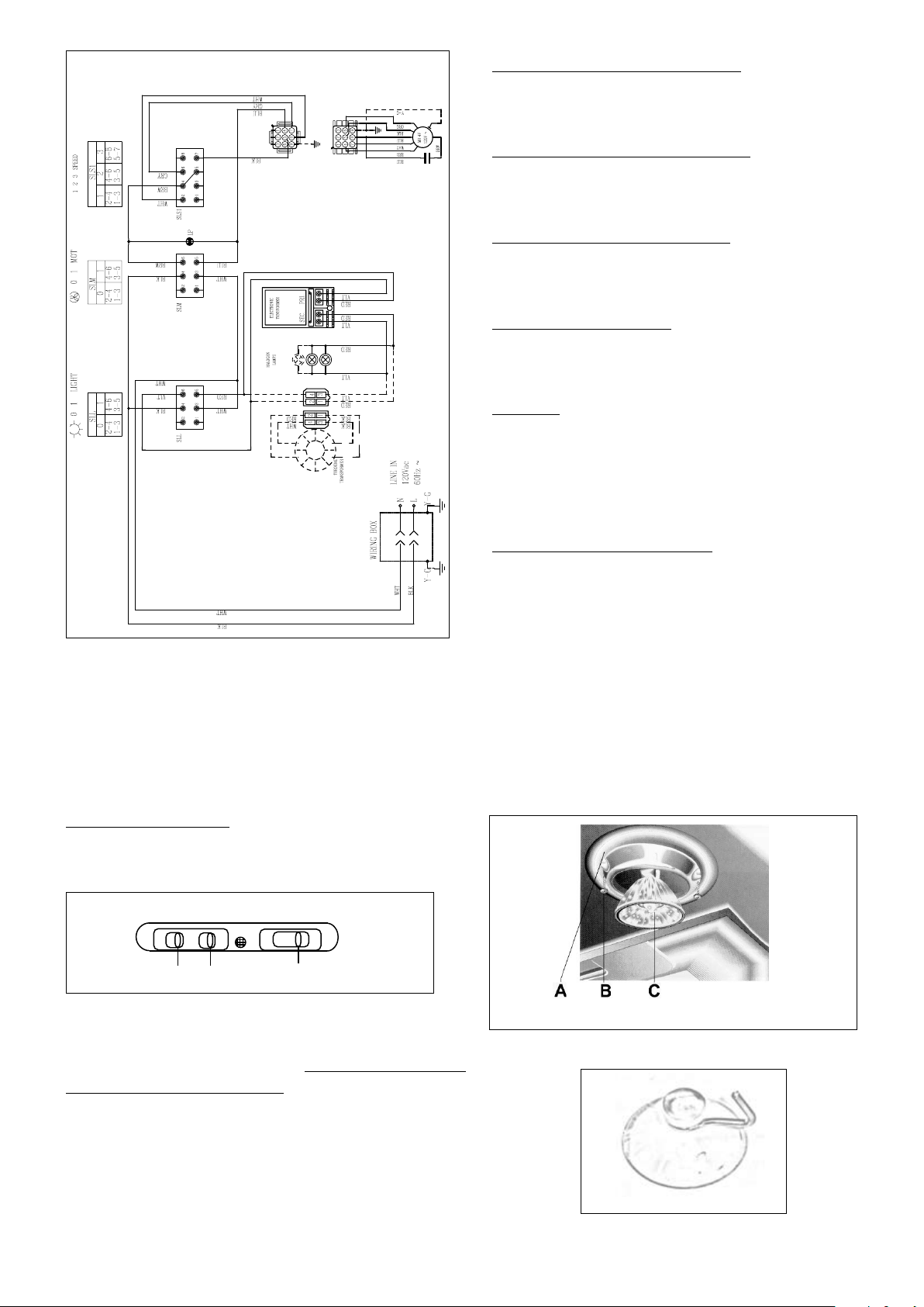
Light On/Off Button ( L )
Blower On/Off Button ( M )
Blower Speed Button ( V )
For Best Results
Cleaning
Replacing the Halogen Lamps
Purchase halogen bulb - (Max 20W, 12V, type MR11 bulb
with glass lens)
Halogen
bulbs burn extremely hot and serious injury could result from
touching a hot bulb.
FIGURE 14
An alternative method to replace the lamps is to use a 1
1/4" suction cup (FIGURE 15). Attach the suction cup to
the bulb and pull rmly down on the bulb and replace with
a new lamp
WIRING DIAGRAM
FIGURE 14
USE AND CARE INFORMATION
For Best Results
Rangehood Control Panel
FIGURE 13
FIGURE 15
FIGURE 13
0 1 0 1 0 1 2
LM V
NOTE: It is not recommended to use the lighting as
a night light or for an extended time beyond normal
cooking times. The halogen lights life span will be
reduced.

FABER WARRANTY & SERVICE (SAVE FOR YOUR RECORDS)
All Faber products are warranteed against any defect in materials or workmanship for the
original purchaser for a period of 1 year from the date of original purchase. This warranty
covers labor and replacement parts. To obtain warranty service, contact the dealer from
whom you purchased the rangehood, or the local Faber distributor. If you cannot identify
a local Faber distributor, contact us at (508) 358-5353 for the name of a distributor in your
area.
The Following is not covered by Faber's warranty:
1. Service calls to correct the installation of your range hood, to instruct you how to use your
range hood, to replace or repair house fuses or to correct house wiring or plumbing.
2. Service calls to repair or replace range hood light bulbs, fuses or lters. Those
consumable parts are excluded from warranty coverage.
3. Repairs when your range hood is used for other than normal, single-family
household use.
4. Damage resulting from accident, alteration, misuse, abuse, re, ood, acts of God,
improper installation, installation not in accordance with electrical or plumbing codes, or
use of products not approved by Faber.
5. Replacement parts or repair labor costs for units operated outside the United States or
Canada, including any non-UL or C-UL approved Faber rangehoods.
6. Repairs to the hood resulting from unauthorized modications made to the
rangehood.
7. Expenses for travel and transportation for product service in remote locations and pickup
and delivery charges. Faber range hoods should be serviced in the home.
Record Your Information Below:
Serial #: __________________________
Date of Purchase: ______________
Version 09/12 - Page 9
OUTILS NÉCESSAIRES À L’INSTALLATION
PIÈCES FOURNIES POUR L’INSTALLATION
PIÈCES NÉCESSAIRES POUR L’INSTALLATION
ACCESSOIRES POUR L’INSTALLATION
• Filtres au Charbon
• Recyclage du kit (4" ; gril de recyclage + ltre de
charbon de bois grands)
24” minimum
30” maximum
distance suggérée entre
le bas de la hotte et
la table de cuisson
18” minimum
distance entre le
placard mural et
le plan de travail
36”
70 5/16” minimum
76
5/16” maximum
jusquʼau
bas du cadre
du placard
24” ou 30” ou 36”
largeur de
lʼouverture du placard
DÉGAGEMENTS DE SÉPARATION À RESPECTER
DIMENSIONS DU PRODUIT
Version 09/12 - Page 10
PLAN DU CONDUIT
-
FIGURES 1 et 2
AVERTISSEMENT!
FIGURE 4
FIGURE 5
CALCUL DE LONGUEUR DU CONDUIT
FIGURE 4
FIGURE 5
Pour de meilleurs résultats, ne pas utiliser plus
de trois coudes de 90
o
. S’assurer qu’il y ait un
minimum de 24 po de conduit droit entre les
coudes si l’on utilise plus d’un coude. Ne pas
installer deux coudes ensemble.
INSTALLATION POUR RECIRCULATION D'AIR
FIGURE 1 FIGURE 2
plafond
soffit inclus
vue de côté
hotte
cuisine de la surface
lʼarmoire
plafond
lʼespace ouvert
vue de côté
hotte
cuisine de la surface
lʼarmoire
FIGURE 3A FIGURE 3B
FIGURE 3C
AVERTISSEMENT
!
Version 09/12 - Page 11
7. -
FIGURE 7
PRÉPARATION DE L'ARMOIRE
1.
2.
3.
4.
5.
FIGURE 4
6
7.
FIGURE 5
FIGURE 6
8.
9.
10.
INSTALLATION DE LA HOTTE
1.
2.
3.
4.
-
5.
6.
(de la FIGURE
7)
Version 09/12 - Page 12
DIAGRAMME DE CÂBLAGE
FIGURE 14
Bouton marche-arrêt de la lumière (L)
Bouton marche-arrêt du ventilateur (M)
Bouton de vitesse du ventilateur (V)
Pour de meilleurs résultats
Nettoyage
Remplacement de la lumière halogène
FIGURE 14
Une méthode alternative pour substituer les lampes est
d'utiliser des 1 1/4"tasses d'aspiration (de la FIGURE 15).
Attachez la tasse d'aspiration à l'ampoule et tirez fermement
vers le bas sur l'ampoule et la substituez avec une nouvelle
lampe.
FIGURE 13
UTILISATION ET ENTRETIEN
Panneau de commandes
FIGURE 13
0 1 0 1 0 1 2
LM V
FIGURE 15
Achat ampoule halogène - (Max 20W, 12V, type MR11
ampoule avec lentille en verre)
FAIRE ATTENTION QUE
L'AMPOULE PEUT ÊTRE CHAUD

FABER GARANTIE ET SERVICE (
ÉCONOMISER POUR VOS ENREGISTREMENTS
)
Faber garantit à l’utilisateur-acheteur d’origine que les produits Faber vendus neufs par nous sont sans vice de
matériel et de main-d’oeuvre d’origine pour une période d’un an à partir de la date d’achat. La garantie couvre
la main-d’oeuvre et les pièces de remplacement. An d’obtenir un service sous garantie, communiquer avec le
marchand où la hotte a été achetée ou le distributeur Faber de la région. Si l’on ne peut trouver de distributeur
Faber, communiquer avec nous au (508) 358-5353 an d’obtenir le nom d’un distributeur dans la région.
Les frais suivants ne sont pas couverts par la garantie Faber :
1. Les appels de service pour corriger l’installation de votre hotte de cuisinière, pour vous indiquer
comment utiliser votre hotte de cuisinière, pour remplacer ou réparer les fusibles de votre maison ou
pour corriger votre câblage ou votre système de plomberie.
2. Les appels de service pour remplacer ou réparer les ampoules, les fusibles ou les
ltres de votre hotte de cuisinière.
3. Les réparations lorsque votre hotte de cuisinière a été utilisée plus que la normale,
c'est-à-dire plus que pour une famille par foyer.
4. Les dommages résultant d’un accident, de l’altération, d’une mal utilisation, d’un acte
de Dieu, d’une installation inappropriée, d’une installation non-conforme aux
normes d’électricité ou de plomberie ou d’une utilisation de l’appareil non approuvée par Faber.
5. Les pièces de remplacement ou les frais de main d’œuvre pour les unités
utilisées en dehors du Canada ou des États Unis, incluant toutes hotte de cuisinière
approuvée par Faber non UL ou C-UL.
6. Les réparations dues à des modications non-autorisées sur votre hotte de cuisinière.
7. Les frais de transport de l’appareil pour réparations à distance.
Enregistrez Votre Information Ci-dessous:
Séquentiel #: __________________________
Date d'achat: ______________