Honda 2022 TRX420TE1 FOURTRAX RANCHER Scooter
Product's Documents
Below are documents related to this product, you can read online or download:
- User Manual - (English) Read Online | Download pdf
Owner Manual Scooter
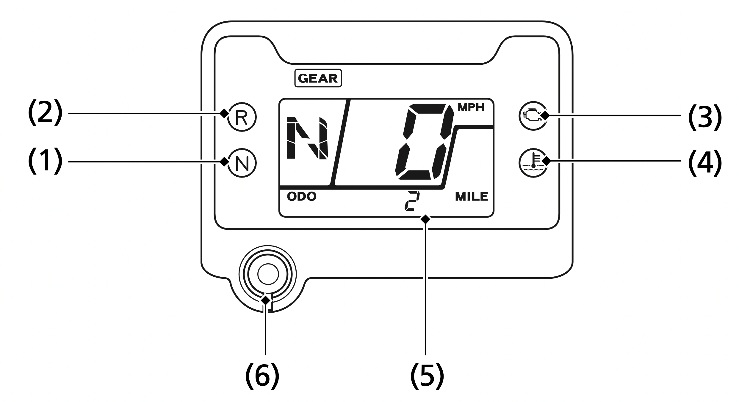
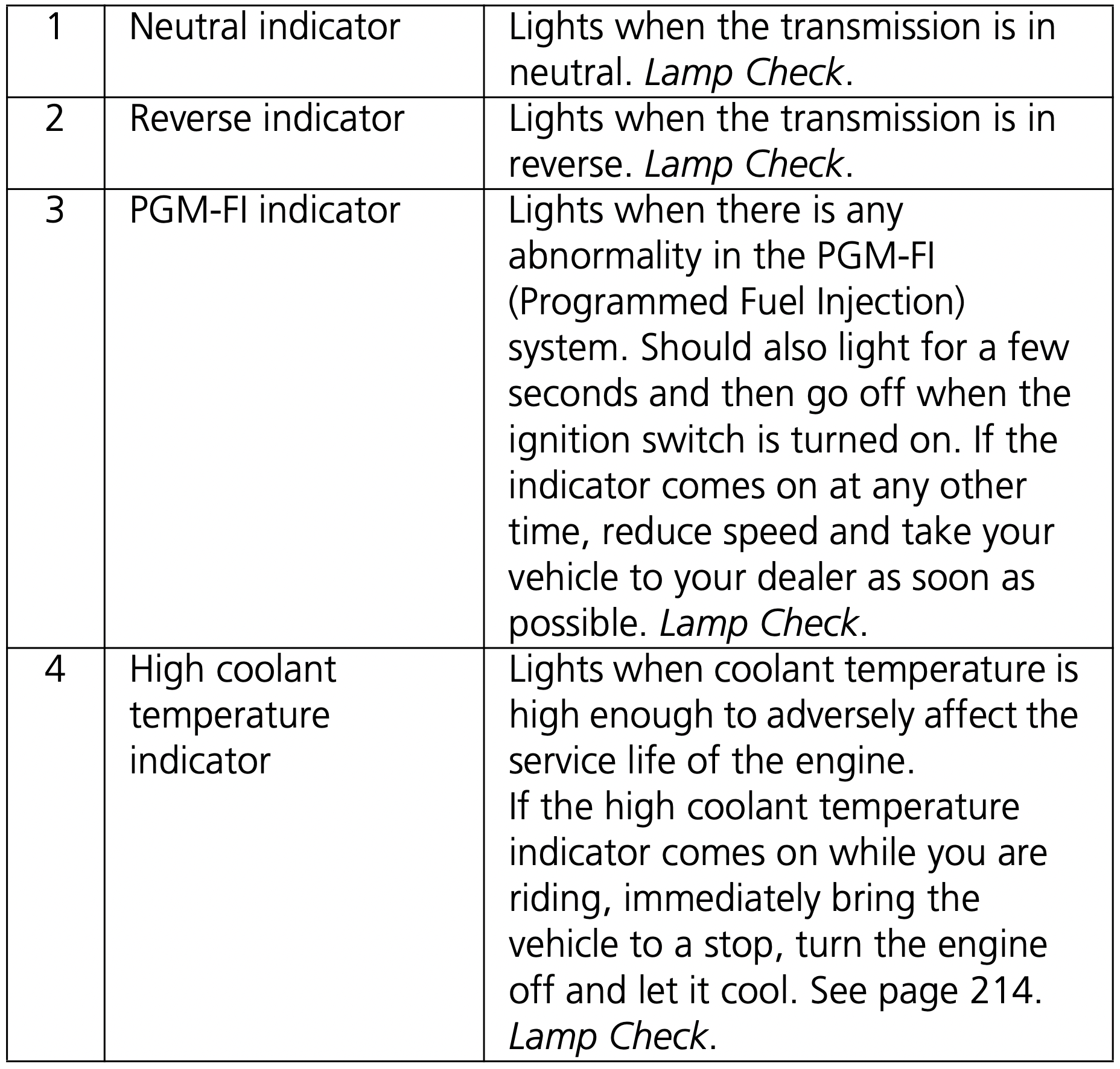
The indicators and displays on your ATV keep you informed, alert you to possible problems, and make your riding safer and more enjoyable. Refer to the indicators frequently. Their functions are described on the following pages.
Lamp Check
Initial lamp check:
The indicators come on for a few seconds and then go off when you turn the ignition switch to ON ( I ).
The high coolant temperature indicator and PGM-FI indicator will temporarily come back on for a few seconds and then go off after initial lamp check.
These indicators are identified in the table on page 17 with the words: Lamp Check.
When applicable, the reverse or neutral indicators come back on and remain on until you shift out of reverse or neutral after initial lamp check.
If one of these indicators does not come on when it should, have your dealer check for problems.
Display Check
When the ignition switch is turned on, the multi-function display (1) will temporarily show all the modes and digital segments and initial message. So you can make sure the liquid crystal display is functioning properly.
The displays are identified in the table on page 18 with the words: Display Check.
If any part of these displays does not come on when it should, have your dealer check for problems.

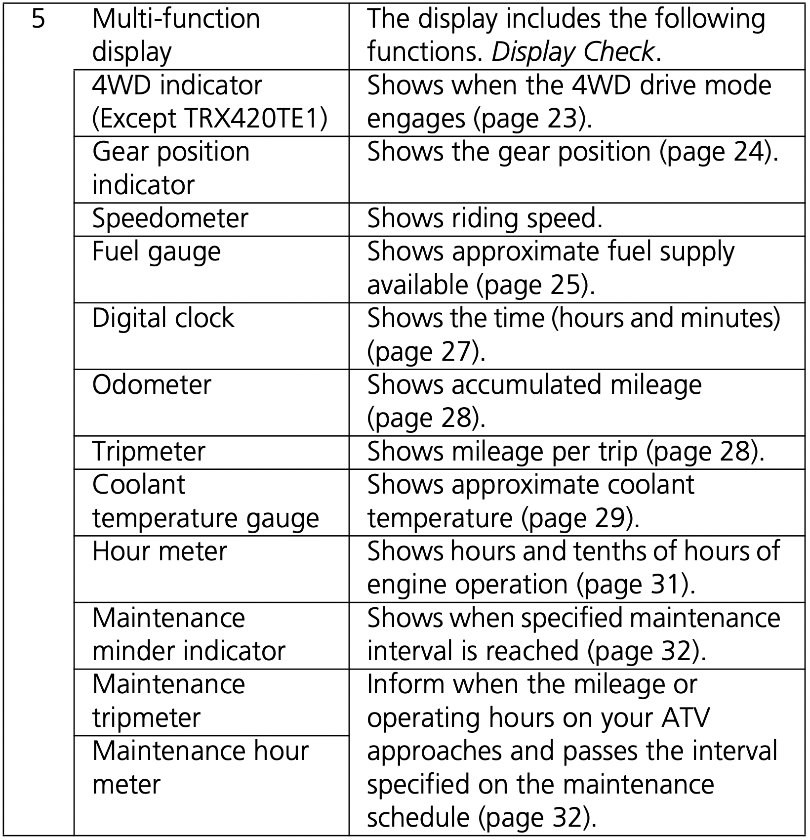
The multi-function display (1) includes the following functions:
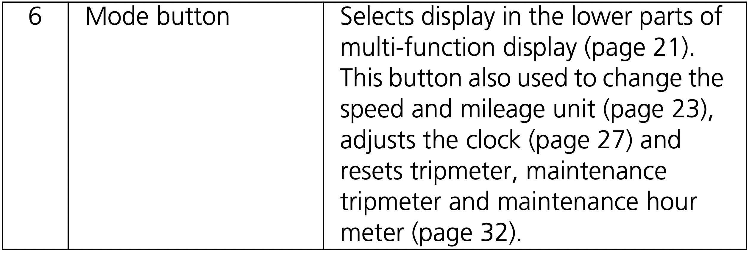
Each time you press the mode button, mode will change as shown in the illustration.
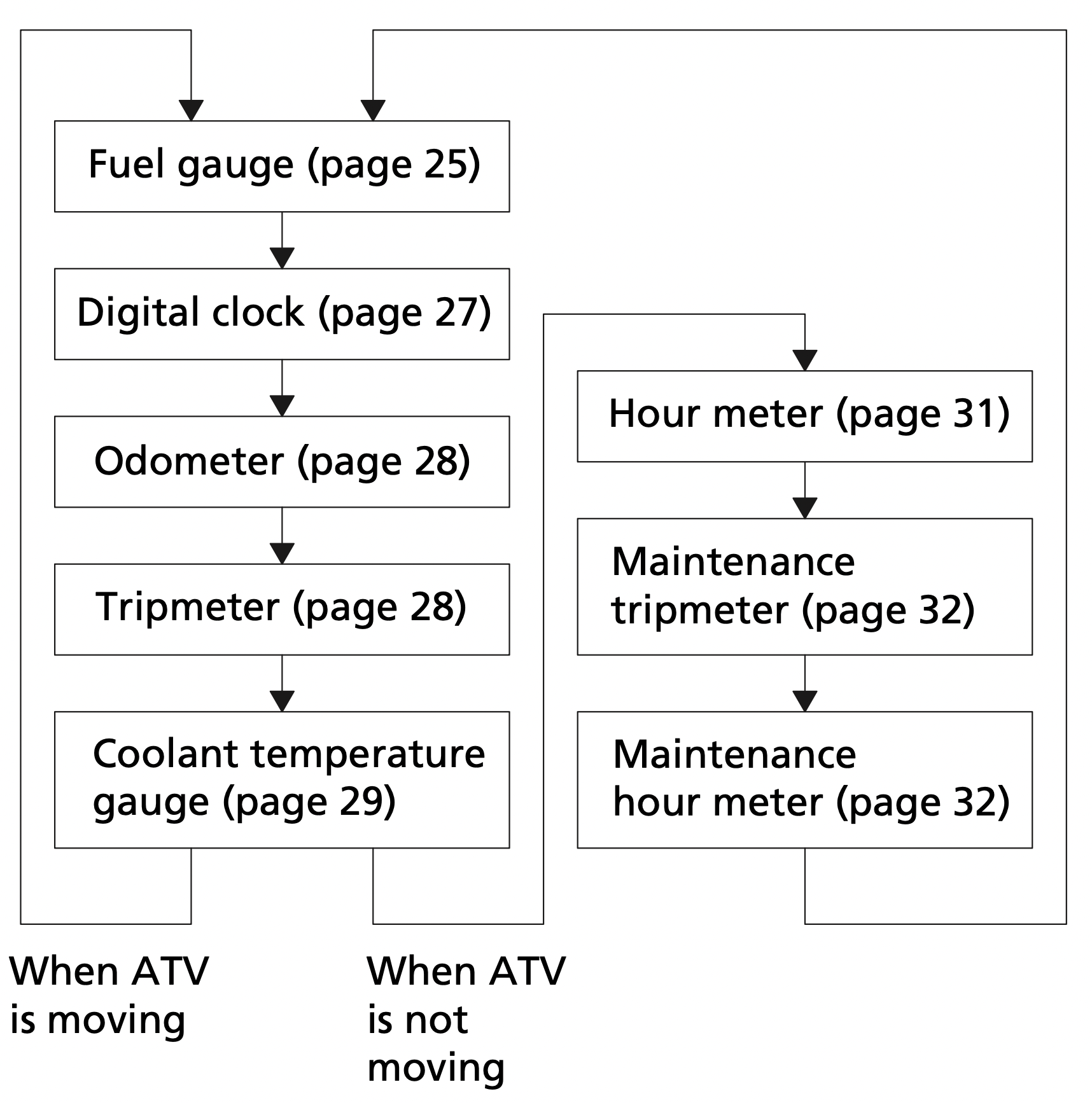
If there is a fuel warning with your ATV, the display will automatically change to the fuel gauge.
If you try to change the display back to ordinary display, it will automatically return to the fuel gauge.
If there is a coolant temperature warning with your ATV, the display will automatically change to the coolant temperature gauge. If you try to change the display back to ordinary display, it will automatically return to the coolant temperature gauge.
The speedometer, odometer, tripmeter and maintenance tripmeter show in either “MPH” and “MILE” or “KM/H” and “KM”.
To change the speed and mileage unit, press and hold the mode button (1) for more than 5 seconds in odometer (page 28) with the ATV stopped.

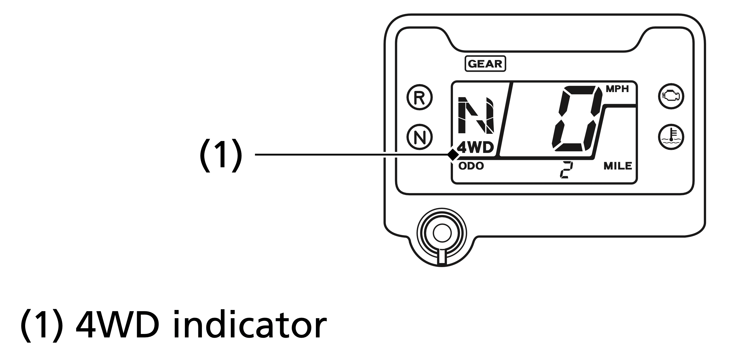
The 4WD indicator (1) appears when the 4WD mode engages (page 35).
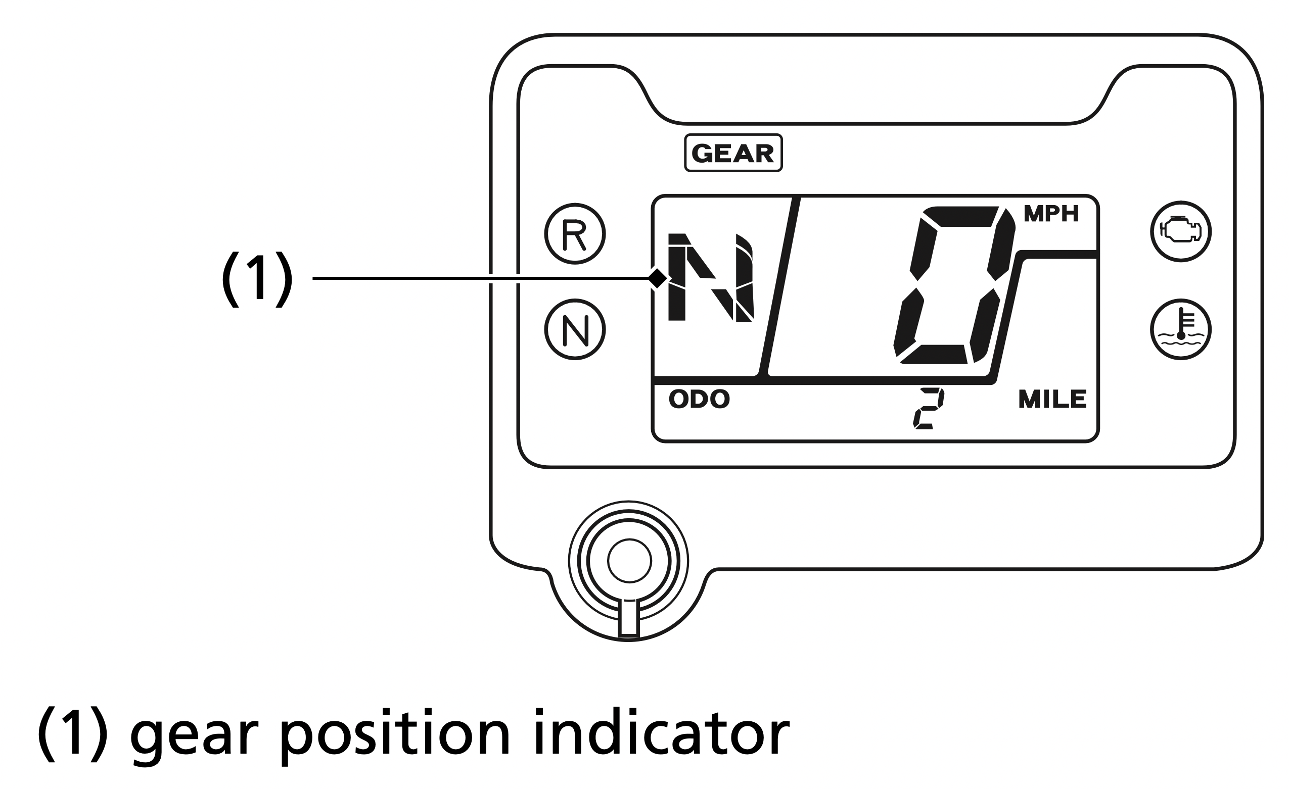
The gear position indicator (1) shows the gear position when the ignition switch is in the ON (q) position.
The indicator displays: N for neutral, R for reverse, and 1 – 5 for the five forward gears.
“–” will be displayed on the gear position indicator when the transmission is not shifted into gear properly. Before riding, check that the gear position is properly displayed on the gear position indicator.
If the gear position indicator shows “–” or blinks, turn the ignition switch to the OFF (w) position, and then turn it back to the ON (q) position again. If the gear position indicator shows “–”, rock the vehicle back and forth and make sure the gear position indicator is displayed properly and then if the gear position indicator still shows “–” or blinks, see your dealer.
If the “–” on the gear position indicator is blinking, see your dealer.
The fuel gauge (1) shows the approximate fuel supply available with fuel mark (2). The fuel tank capacity is: 3.88 US gal (14.7 ℓ)
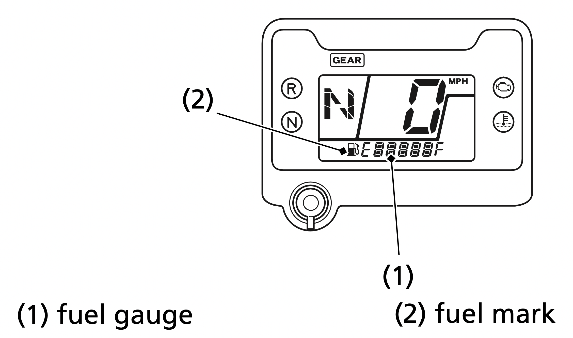
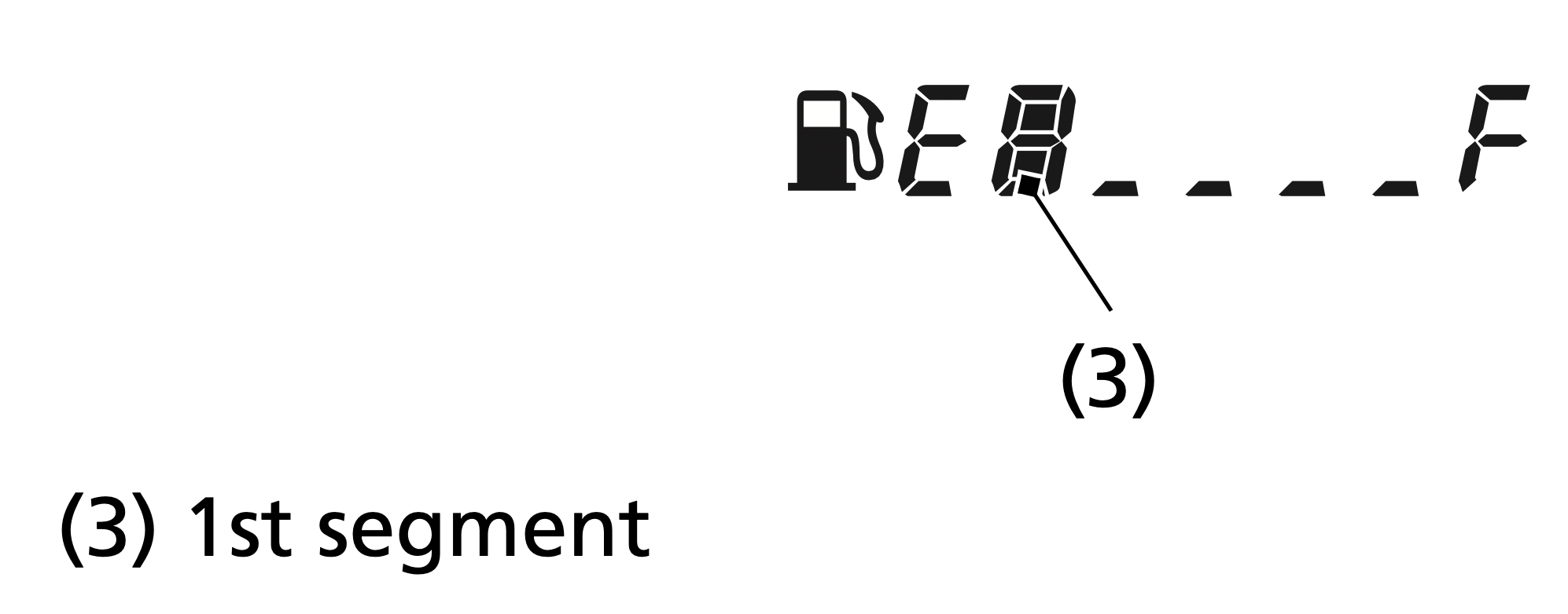
Regardless of what mode the display is in, when the fuel level reaches only 1st segment (3), the display will automatically switch to the fuel gauge display. You should refuel as soon as possible.
The amount of fuel remaining when there is only 1st segment is approximately: 1.82 US gal (6.9 ℓ)
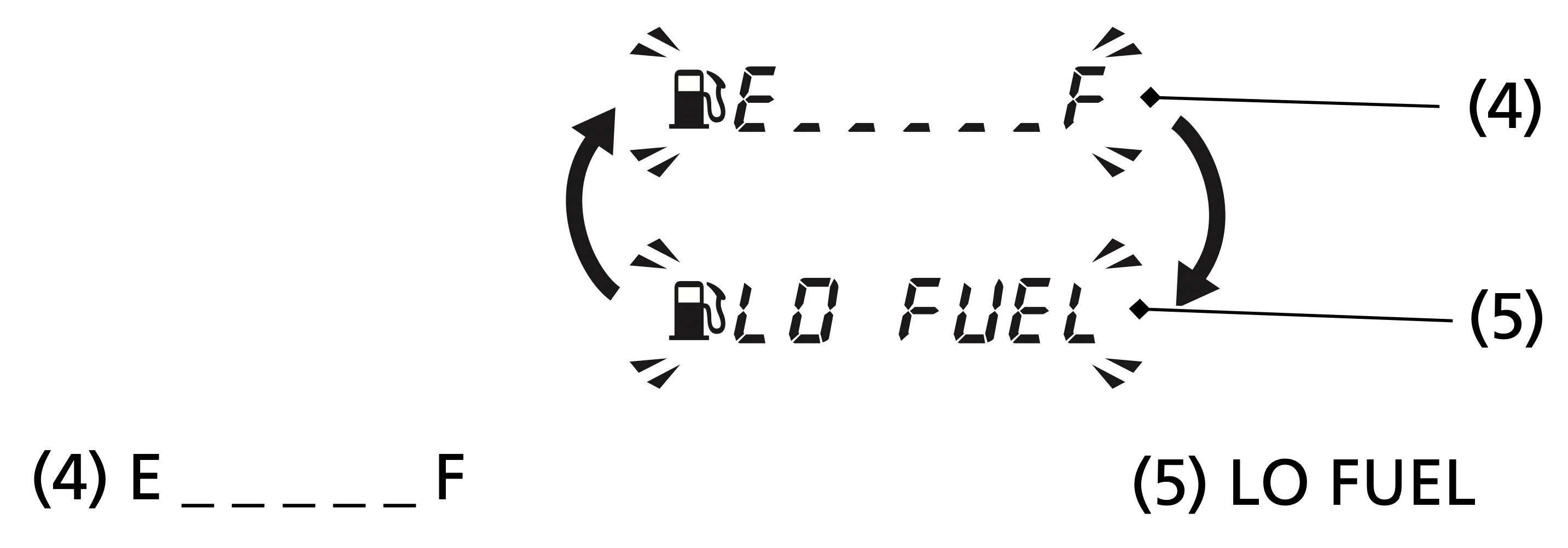
When the fuel gauge show E _ _ _ _ _ F (4) and LO FUEL (5) blink 3 times alternately and fuel mark blinks, you should refill the tank as soon as possible.
The amount of fuel reserve is approximately: 1.29 US gal (4.9 ℓ)
Fuel gauge failure:
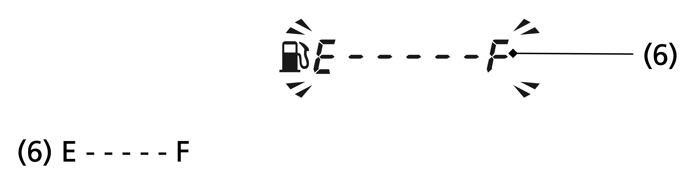
If the fuel gauge function fails E - - - - - F (6) will blink.
See your dealer.
(The fuel mark disappears except the fuel gauge display)
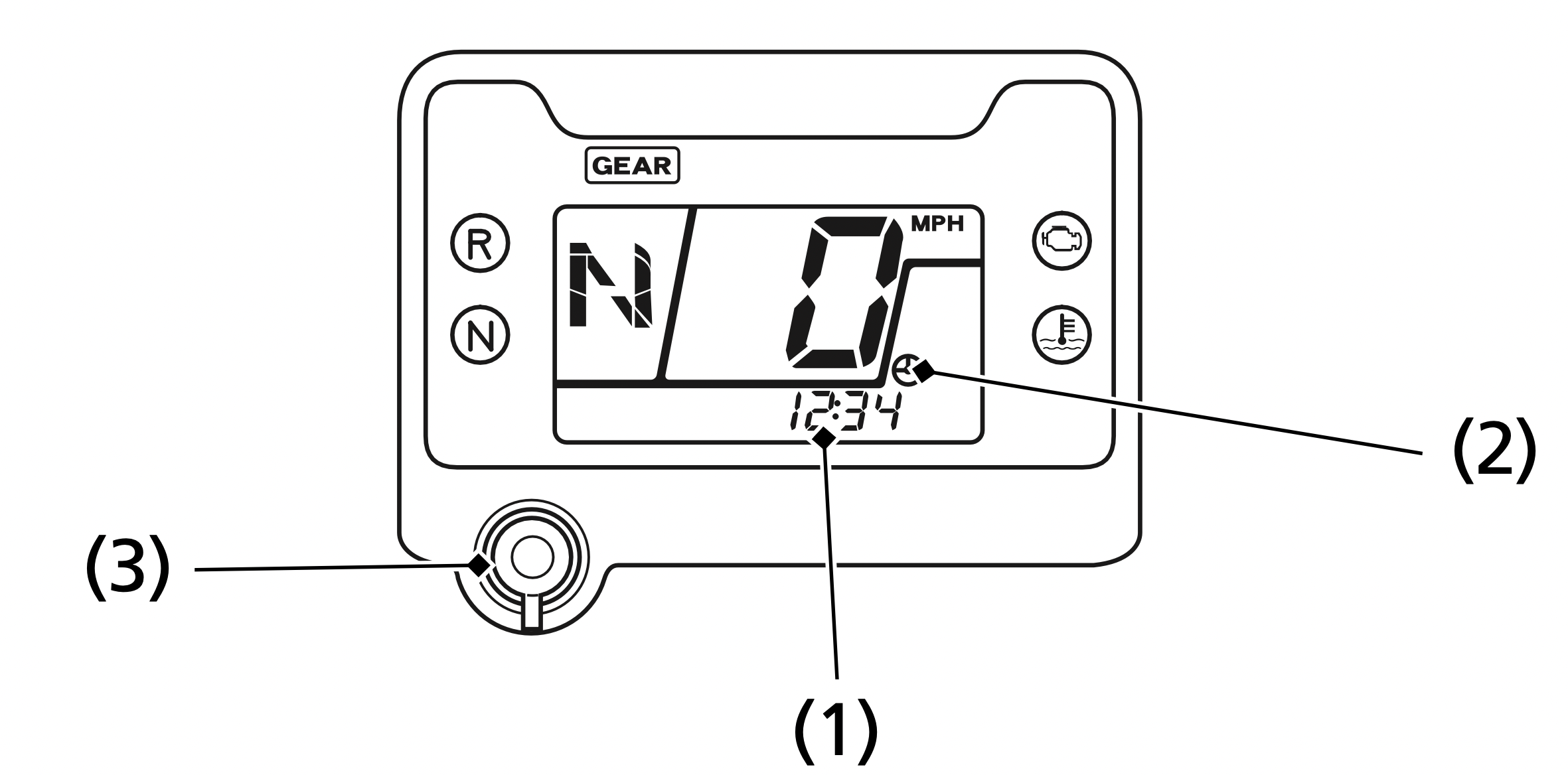
The digital clock (1) displays hours and minutes with the clock mark (2), when the ignition switch is ON (q).
To adjust the time, proceed as follows:
After the battery is reconnected (page 184), check the clock. Readjust the clock if necessary.
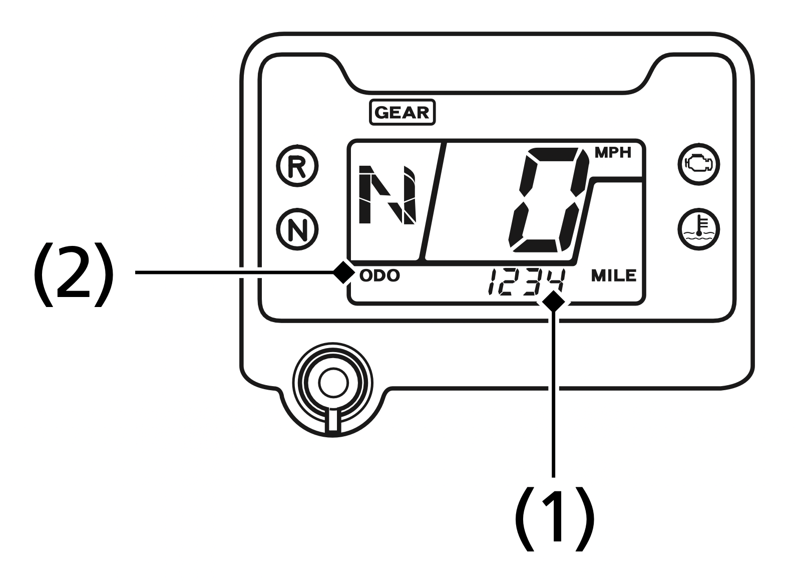
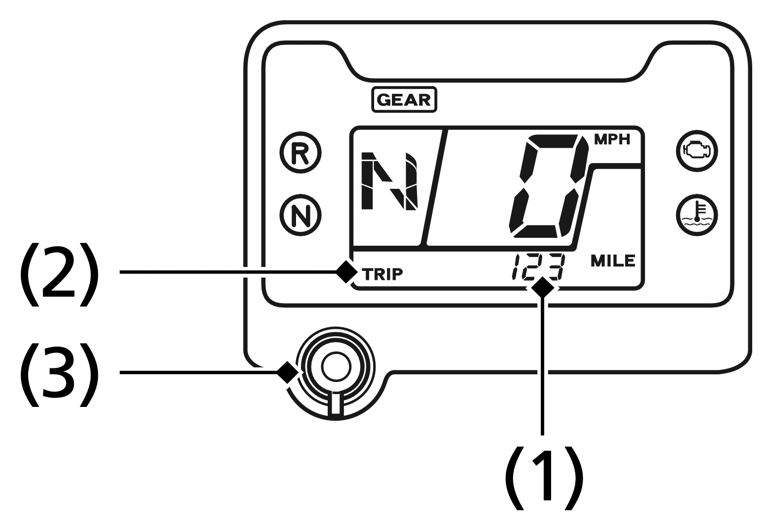
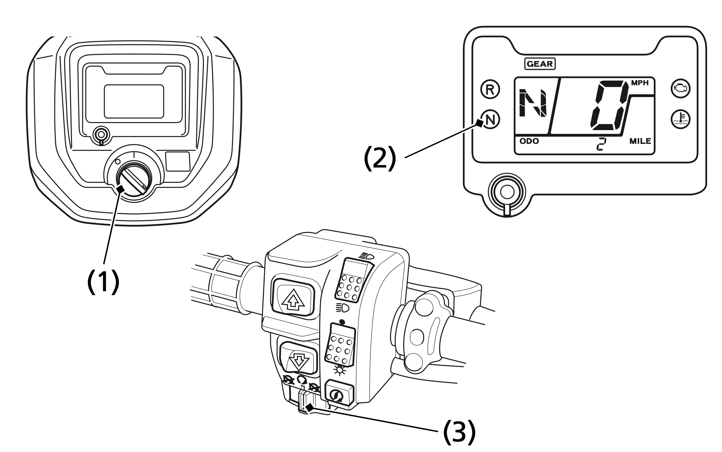
The odometer (1) registers total distance traveled in mileage while the ignition is ON (q) with the ODO display (2). The odometer locks at 999999 when the readout exceeds 999999.
The tripmeter (1) shows mileage per trip with the TRIP display (2), while the ignition is ON (q) since you last reset the tripmeter. The tripmeter returns to 0.0 when the read-out exceeds 999.9. To reset the tripmeter to zero, press the mode button (3) and hold it in for at least 2 seconds in the tripmeter mode.
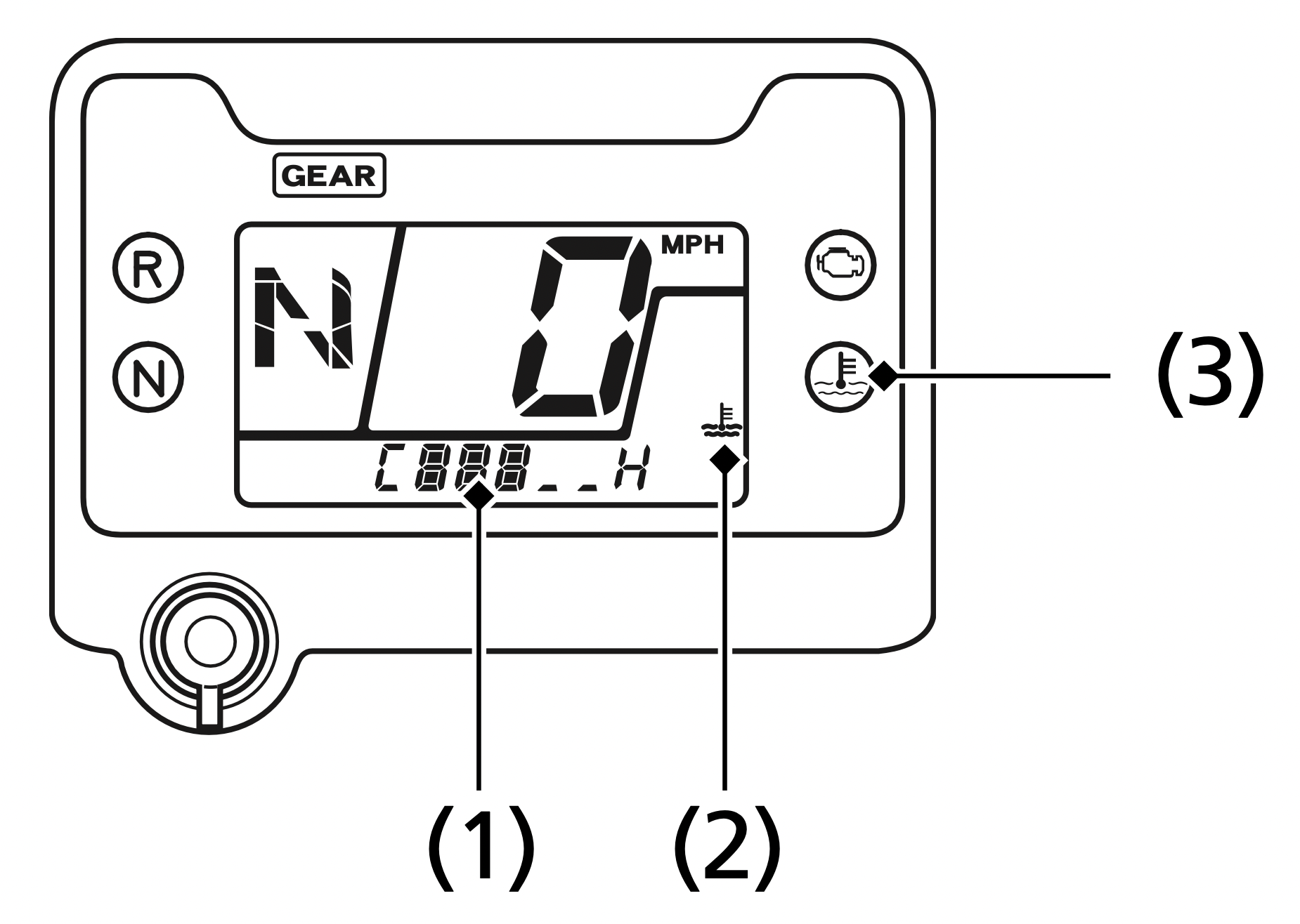
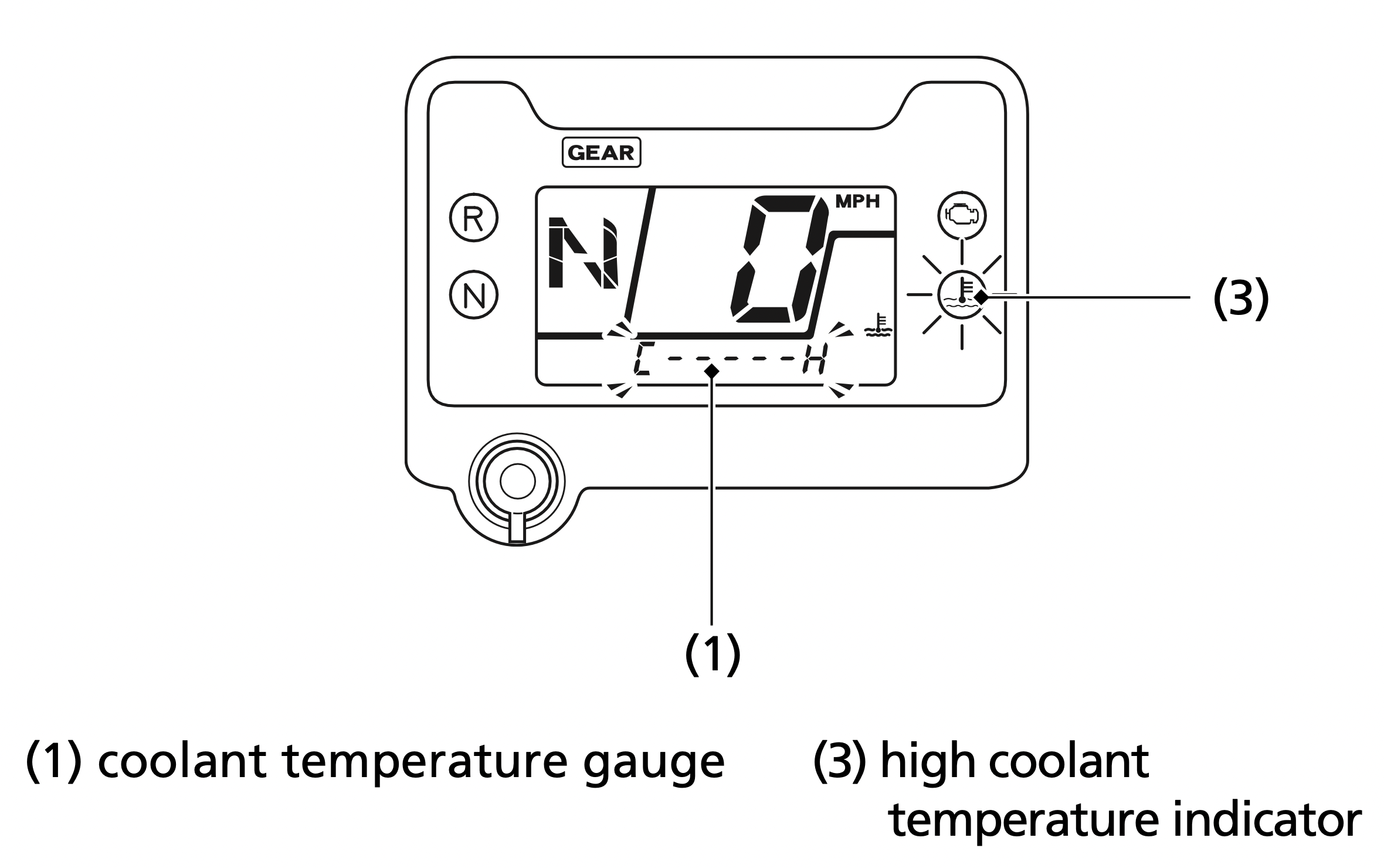
The coolant temperature gauge (1) with the coolant temperature mark (2) shows the coolant temperature.
When coolant temperature is low, the coolant temperature gauge will display “Lo”.
If all sections of the coolant temperature gauge and high coolant temperature indicator are on (automatically appears in the display) while you are riding, immediately stop the vehicle, turn the engine off and check the coolant reserve tank level. See page 137.
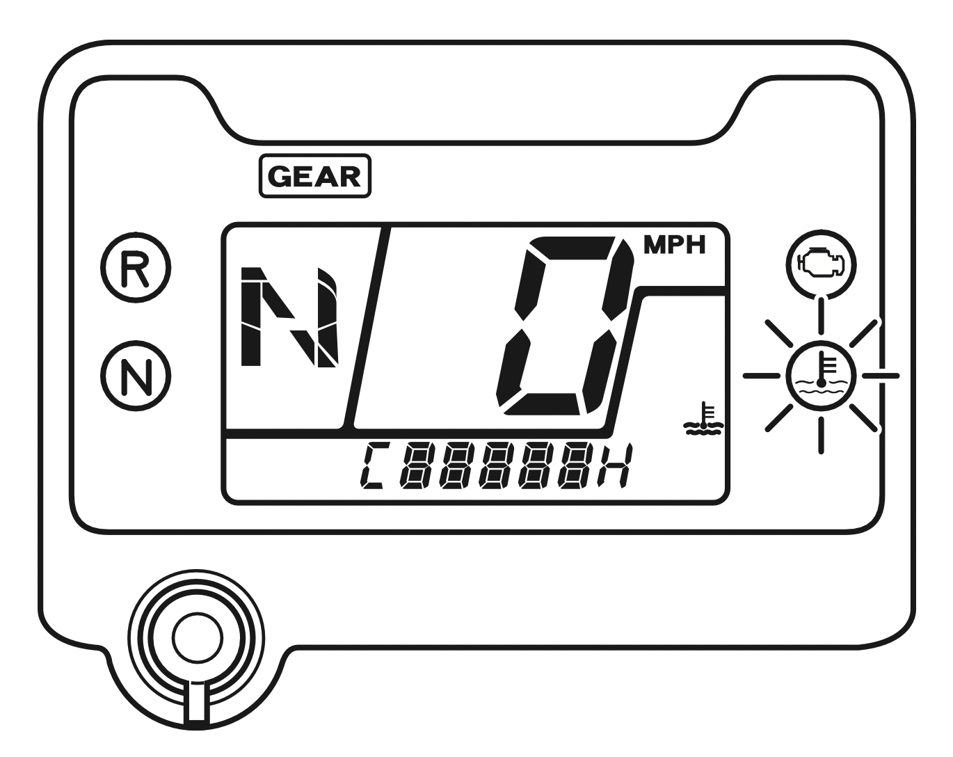
NOTICE: Continuing to ride with an overheated engine can cause serious engine damage.
Coolant temperature gauge failure:
If the coolant temperature system has an error, the coolant temperature gauge (1) will flash and preferentially appear in the display, and/or high coolant temperature indicator (3) will turn on. If this occurs, see your dealer as soon as possible.
The hour meter (1) shows accumulated hours while the ignition switch is ON ( I ) with the hour meter mark (2). The hour meter provides accurate service period information for initial and regular maintenance. The hour meter locks at 99999.9 when the readout exceeds 99999.9.

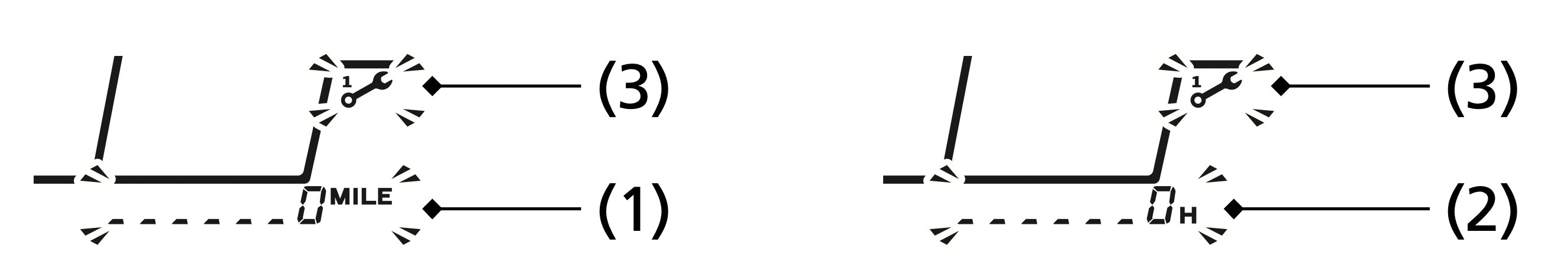
The maintenance tripmeter (1), the maintenance hour meter (2) and maintenance minder indicator (3) inform you when the mileage or operating hours on your ATV approaches and passes the maintenance interval specified on the maintenance schedule (page 106).
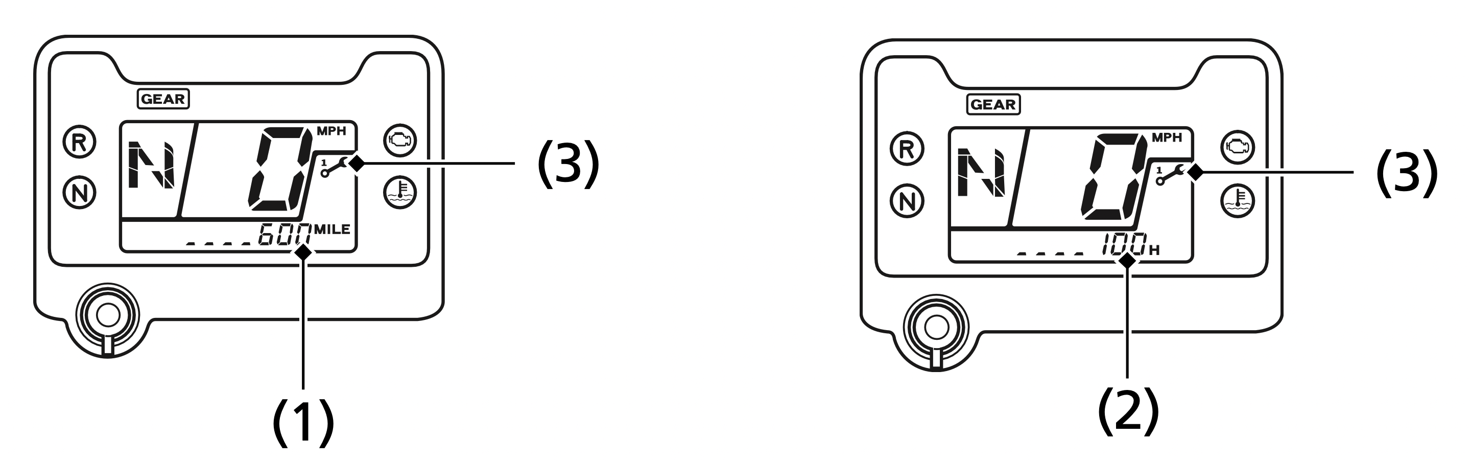
The maintenance tripmeter, or the maintenance hour meter and maintenance minder indicator will blink, when they reach their setting values.
Reset the meters after each scheduled maintenance.
To reset the maintenance tripmeter and the maintenance hour meter, press and hold the mode button and turn the ignition switch to ON ( I ). Continue to hold the mode button, the maintenance minder indicator will light up, and after 2 seconds will flash twice, the maintenance minder indicator is reset.
Also the maintenance tripmeter and maintenance hour meter will reset.
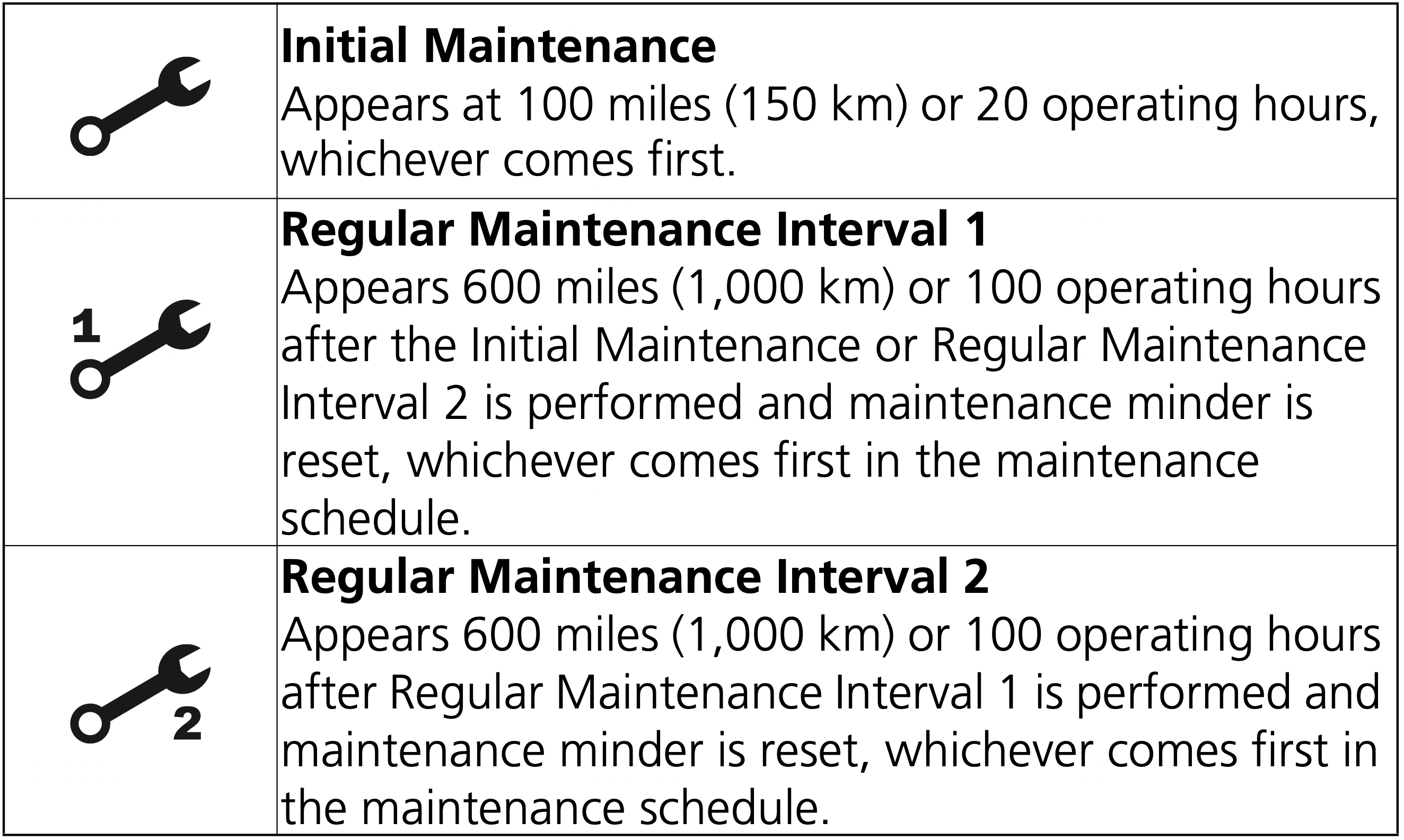
Maintenance Minder Indicators:
If the maintenance is done before the setting interval, be sure to reset the meters after the maintenance.
Modifying your ATV or using non-Honda accessories can make your ATV unsafe.
Before you consider making any modifications or adding an accessory, be sure to read the following information.
WARNING:
We strongly recommend that you use only Honda Accessories that have been specifically designed and tested for your ATV. Because Honda cannot test all other accessories, you must be personally responsible for proper selection, installation, and use of non-Honda accessories.
Check with your dealer for assistance and always follow these guidelines:
We strongly advise you not to remove any original equipment or modify your ATV in any way that would change its design or operation. Such changes could seriously impair your ATV’s handling, stability, and braking, making it unsafe to ride.
We also advise you not to make any modifications or remove any equipment (such as the USDA qualified spark arrester or emission control system components) that would make your ATV illegal in your area.
Removing or modifying your lights, exhaust system, emission control system, or other equipment can also make your ATV illegal.
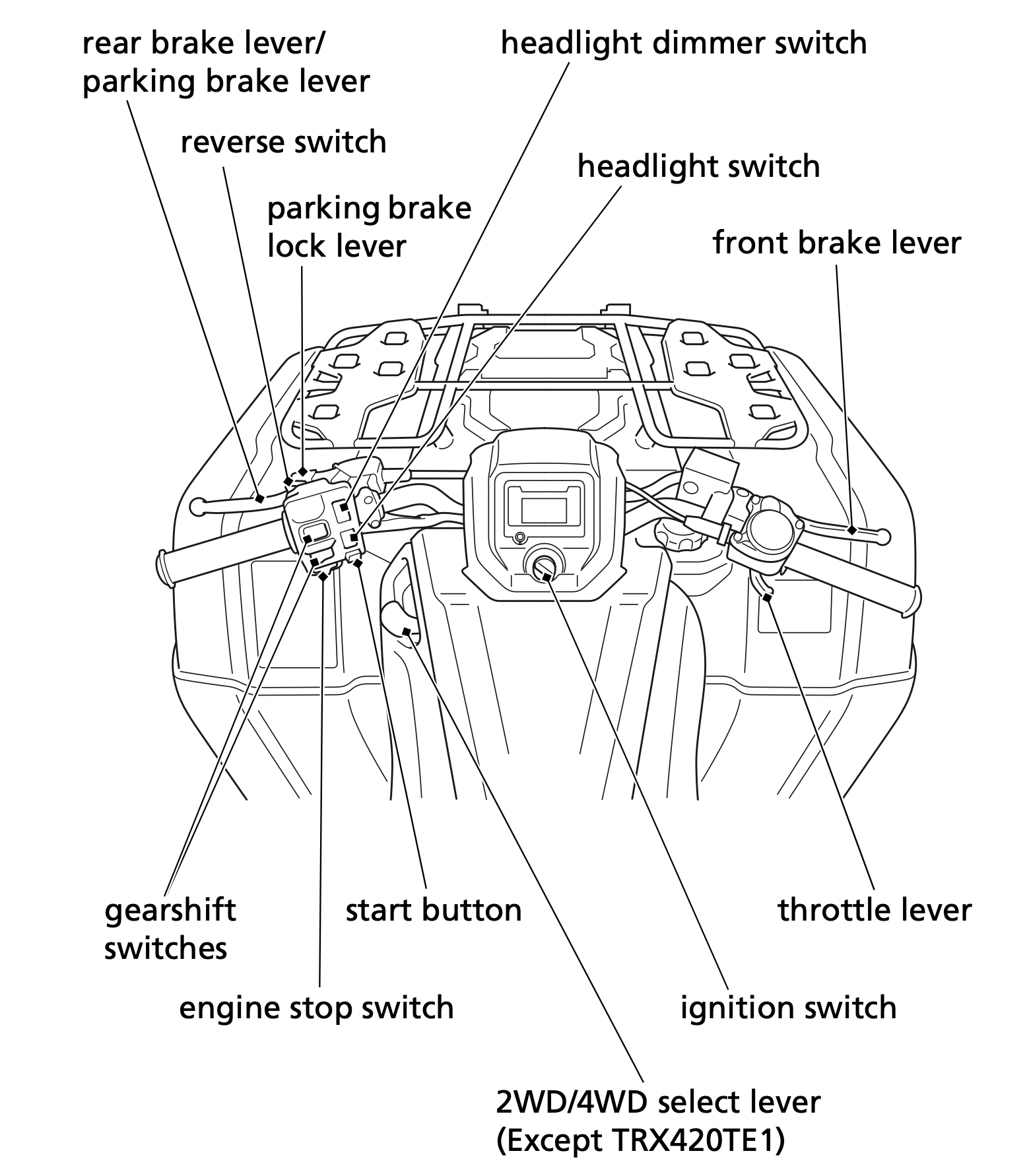
Always follow the proper starting procedure described below.
For your safety, avoid starting or operating the engine in an enclosed area such as a garage. Your ATV’s exhaust contains poisonous carbon monoxide gas which can collect rapidly in an enclosed area and cause illness or death.
WARNING:
Confirm the following:
 ).
).This ATV is fuel-injected with an automatic choke. Follow the procedure indicated below.
Any Air Temperature
The engine will not start if the throttle is fully open (because the electronic control module cuts off the fuel supply).
Snapping the throttle or fast idling for more than 5 minutes may cause exhaust pipe and muffler discolorations.
If the engine fails to start after repeated attempts, it may be flooded with excess fuel. To clear a flooded engine:
 ).
).If the engine does not start, wait 10 seconds, then follow steps 1 – 4 again.
If the engine still won’t start, refer to If Your Engine Quits or Won’t Start, page 204.
Your vehicle’s banking (lean angle) sensor system is designed to automatically stop the engine if the vehicle is overturned.
Before restarting the engine, you must turn the ignition switch to the OFF ( O ) position and then back to ON ( I ). The engine will not restart until you perform this procedure.
You can restart the engine while the vehicle is stopped by squeezing the front brake lever and pressing the start button.
Do not press the throttle lever while starting in gear. The engine will not start if the throttle is fully open (because the electronic control module cuts off the fuel supply).
Once you have started the engine, release the front brake lever, then apply throttle gradually.
Normal Engine Stop
To stop the engine, make sure the transmission is in neutral by checking that the neutral indicator light is on, then turn the ignition switch to OFF ( O ).
The engine stop switch should normally remain in the RUN (  ) position even when the engine is OFF.
If your ATV is stopped with the engine stop switch OFF (  ) and the ignition switch ON ( I ), the battery will discharge.
Emergency Engine Stop
To stop the engine in an emergency, use the engine stop switch. To operate, slide the switch to either OFF (  ) position.
General Guidelines
Keeping your ATV well-maintained is the best way to reduce the possibility of having a problem while riding. However, problems can arise even with well-maintained machines.
Remember to take along your owner’s manual, the tool kit that came with your ATV, and any other items (such as tire repair supplies and additional tools) that might help you solve a problem on your own.
If something goes wrong during a ride, the first thing to do is stop as soon as you safely can. Do not continue riding if you have a flat tire, or you hear an unusual noise, or your ATV just doesn’t feel right. If you continue riding, you could cause more damage and endanger your own safety.
After stopping, take time to assess the situation. Carefully inspect your ATV to identify the problem, then consider your options before you decide what to do.
If a problem is relatively minor and you have the tools, supplies, and skills to make a permanent repair, you may be able to fix it on the trail and continue riding. Or, you may be able to make a temporary repair that allows you to slowly ride back to your base where you can make a permanent repair or get help.
When a problem is more serious — or you don’t have the tools, supplies, experience, or time to deal with it — you need to choose the safest way to get yourself and your ATV back to base. For example, if you are close enough, you (or you and another person) might be able to push it back.
Should you ever have a problem while riding, please follow these guidelines:
Additional recommendations for specific problems follow.
Proper operation and maintenance can prevent starting and engine performance problems. In many cases, the cause of the problem may be a simple operational oversight.
If you have a problem starting the engine — or experience poor engine performance — the following information may help you. If you can’t correct the problem, see your dealer.
If your ATV won’t start, listen as you press the start button. If you don’t hear the starter motor turning, refer to the Starter motor doesn’t operate symptom. If you can hear the starter motor working normally, refer to the Starter motor works, but the engine won’t start symptom.
|
SYMPTOM: Starter motor doesn’t operate. |
|
|
POSSIBLE CAUSE |
WHAT TO DO |
|
ignition switch OFF |
Turn the ignition switch ON. |
|
engine stop switch OFF |
Slide the engine stop switch to RUN. |
|
transmission not in neutral |
Shift into neutral. |
|
blown fuse |
Replace with a new fuse of the same rating (page 216). |
|
battery lead loose |
Tighten the battery lead. |
|
low (or dead) battery |
Charge the battery (page 186). If charging doesn’t help, see your dealer. |
|
faulty starter motor |
If all possible causes are negative, the starter motor may be faulty. See your dealer. |
|
SYMPTOM: Starter motor works, but the engine won’t start. |
|
|
out of fuel |
Fill the fuel tank. |
|
flooded engine |
See Flooded Engine (page 75). |
|
loose or unconnected spark plug cap |
Install the spark plug cap securely. If the engine still won’t start, see your dealer. |
|
loose battery cables |
Tighten the battery terminal bolts. |
|
weak battery |
Charge the battery (page 186). If charging doesn’t help, see your dealer. |
|
SYMPTOM: Engine starts, but runs poorly. |
|
|
high coolant temperature |
Check the coolant temperature gauge and high coolant temperature indicator. Refer to If the High Coolant Temperature Indicator Lights, page 214. |
|
runs erratically, misfires |
See your dealer. |
|
blubbers (rich fuel mixture) |
See your dealer. |
|
sooty exhaust (rich fuel mixture) |
See your dealer. |
|
detonates or pings under load |
If applicable, switch to the recommended octane gasoline (page 119) or change your brand of gasoline. If the problem persists, see your dealer. |
|
afterfires (backfires) |
See your dealer. |
|
pre-ignition (runs on after ignition switched OFF) |
See your dealer. |
|
SYMPTOM: Engine starts, but runs poorly or dies when hot. |
|
|
poor or inadequate fuel flow due to clogged fuel filter |
See your dealer. |
If one or both shift switches do not function, see the following instructions. If proper function cannot be restored, see your dealer.
When the engine is running:
When the engine is stopped and the ignition switch is “ON” ( I ):
When the battery is low (or dead):
If the shift switches do not operate, use the following procedure to manually select a gear so you may drive the vehicle to a location where it can be loaded and transported to your dealer.
How to Shift Gears Manually:

Do not attempt to shift gears manually using the gear change tool while riding.
If the transmission is shifted manually when the electric shift system is functioning, the system will shutdown automatically and the shift switches will not operate. To reactivate the system, turn the ignition switch to the “OFF” (O) position, then turn it back to the “ON” (I) position.
How you handle a flat tire on the trail depends on how serious the tire damage is, and what tools and supplies you have with you.
If you have a slow leak or a minor puncture, use the plug method to make a temporary repair. (The plug method is applied from the outside of the tire and is the same as that for conventional tubeless tires.)
A plug-type repair kit, available at most auto parts stores or service stations, provides a plug, an installation tool, tire cement, and an instruction sheet. Follow the instructions provided with the repair kit to make a temporary repair.
As soon as possible, have the tire permanently repaired by your dealer. Any tire that cannot be repaired should be replaced.
Whenever the ATV is to be operated far from service facilities or available transportation, we recommend that you carry a tire pump and a repair kit with the vehicle.
If the leak is more serious, or a temporary repair doesn’t hold, the tire must be replaced. The tire will also need to be replaced if it is damaged (page 177). Replacing a tire involves removing and reinstalling the wheel (page 212).
If you are unable to repair a flat tire on the trail, you will need to send for help. We strongly recommend that you do not try to ride with a flat tire. The ATV will be hard to handle, and if the tire comes off the rim, it may lock up the wheel and cause you to crash.
WARNING:
Emergency Wheel Removal/Installation
Refer to Safety Precautions on page 103.
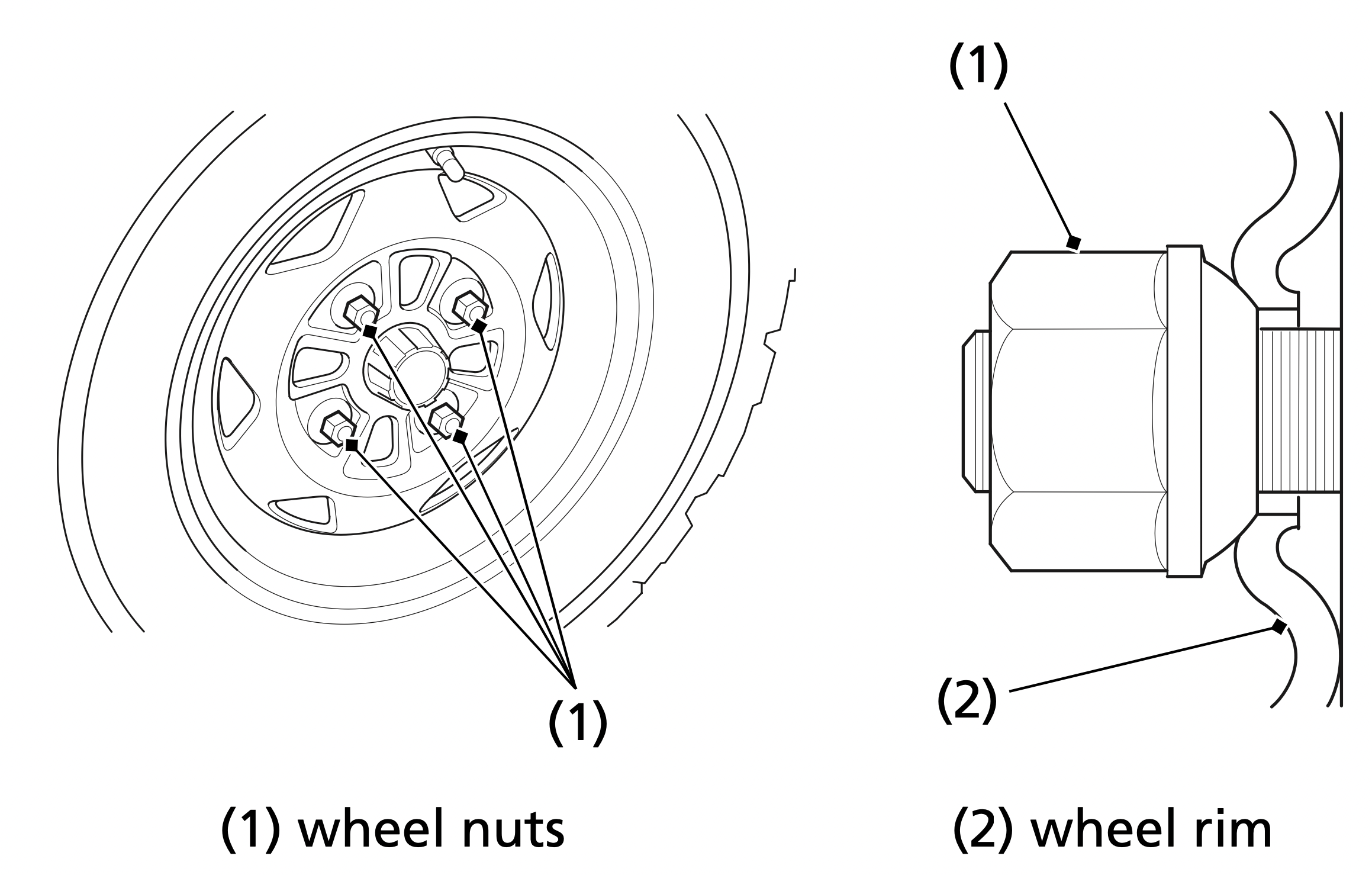
Removal
Installation
If a torque wrench was not used for installation, see your dealer as soon as possible to verify proper assembly. Improper assembly may lead to loss of braking capability.
Normally, the high coolant temperature indicator will only light momentarily when you turn the ignition to ON (I).
High coolant temperature may be caused by restriction of air flow to the radiator (such as mud caked on the radiator), extended idling, an oil leak, a coolant leak, a low oil level, a low coolant level, or extended operation under adverse conditions.
If the all segment of the coolant temperature gauge and high coolant temperature indicator are on while you’re riding, don’t ignore it. Pull safely to a stop. Stop the engine as soon as it’s safe to do so, and let it cool.
NOTICE
Continuing to ride with high coolant temperature or an overheated engine can cause serious engine damage.
If you are able to resume riding, continue to monitor the coolant temperature gauge and high coolant temperature indicator frequently.
If there is an oil leak — do not ride the ATV until the leak is repaired by your dealer (page 194).
If there’s a mild coolant leak, you can ride for awhile, carefully watching the coolant temperature gauge and indicator. Be prepared to stop and add more coolant or water. If the leak is bad, transport your ATV to your dealer (page 194).
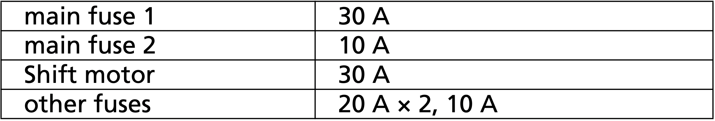
All of the electrical circuits on your ATV have fuses to protect them from damage caused by excess current flow (short circuit or overload).
If something electrical on your ATV stops working, the first thing you should check for is a blown fuse (1).
Check all the fuses before looking elsewhere for another possible cause of the problem. Replace any blown fuses and check component operation.

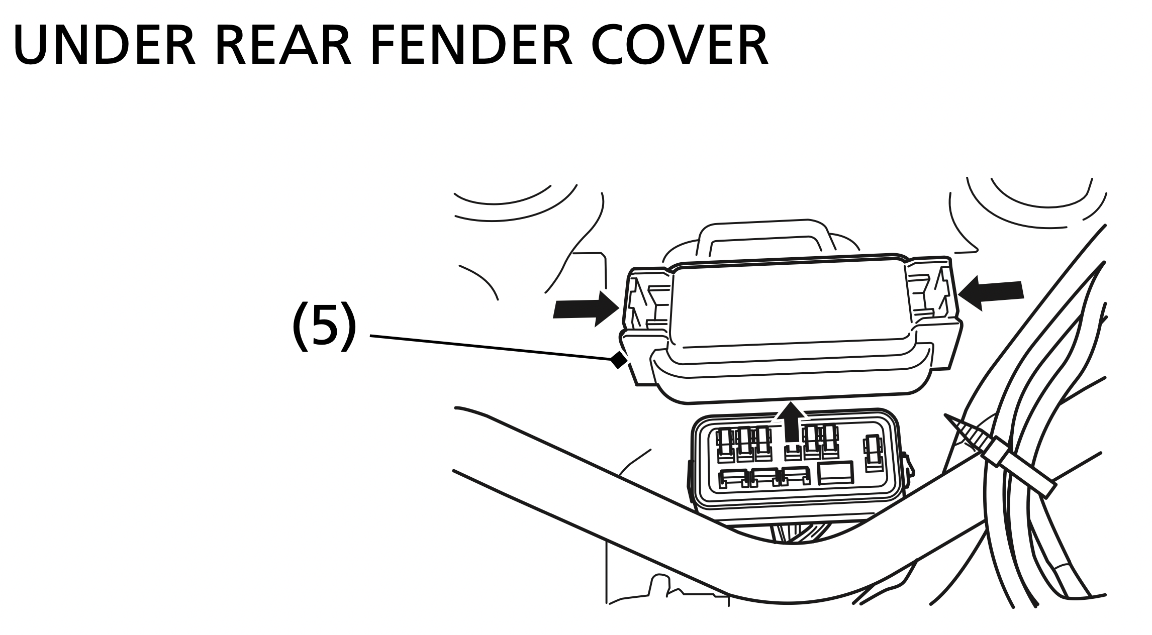
The main fuse and the circuit fuses are located under the rear fender cover.
Recommended Fuses
Main and Shift Motor Fuses Access
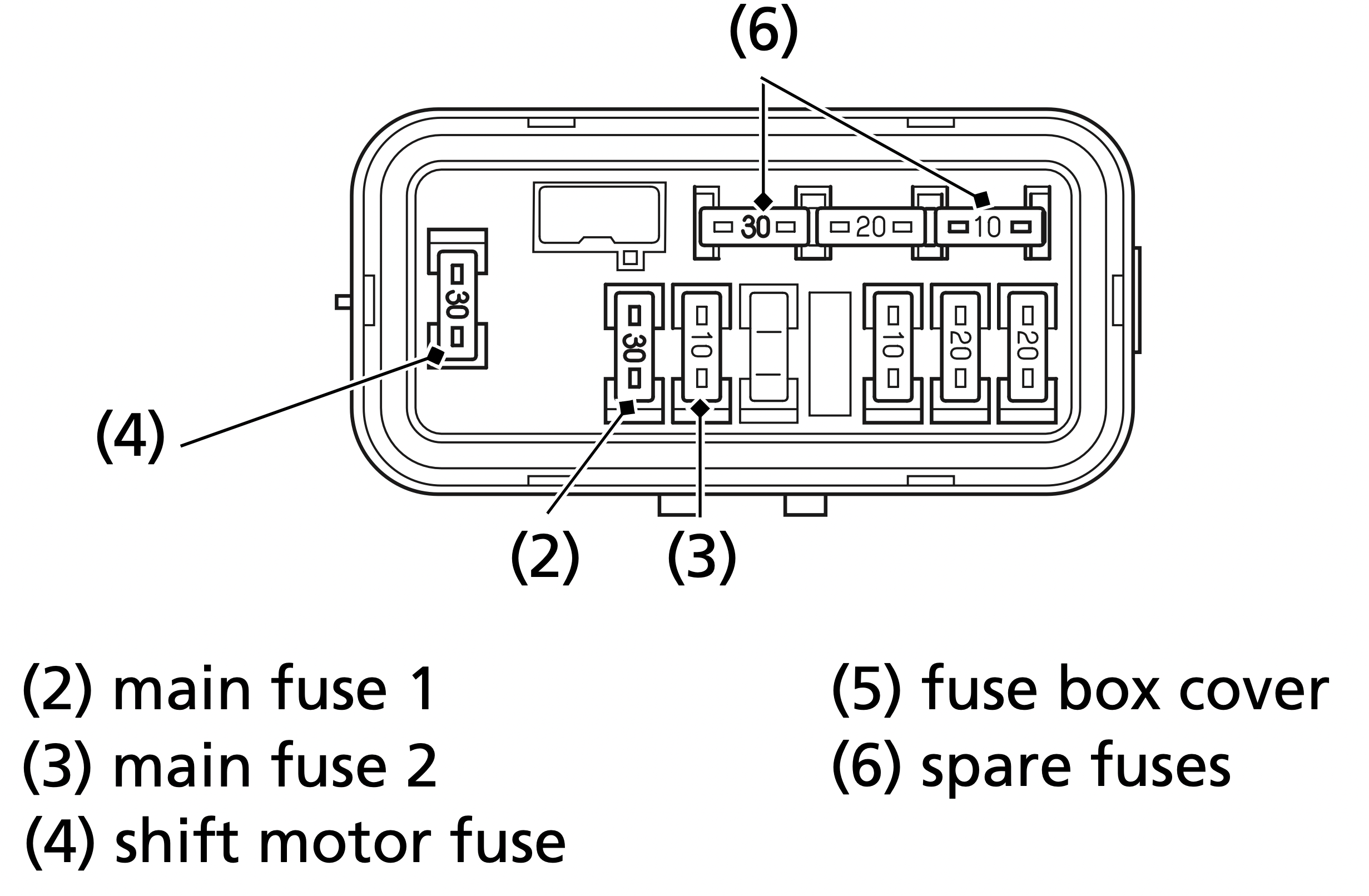
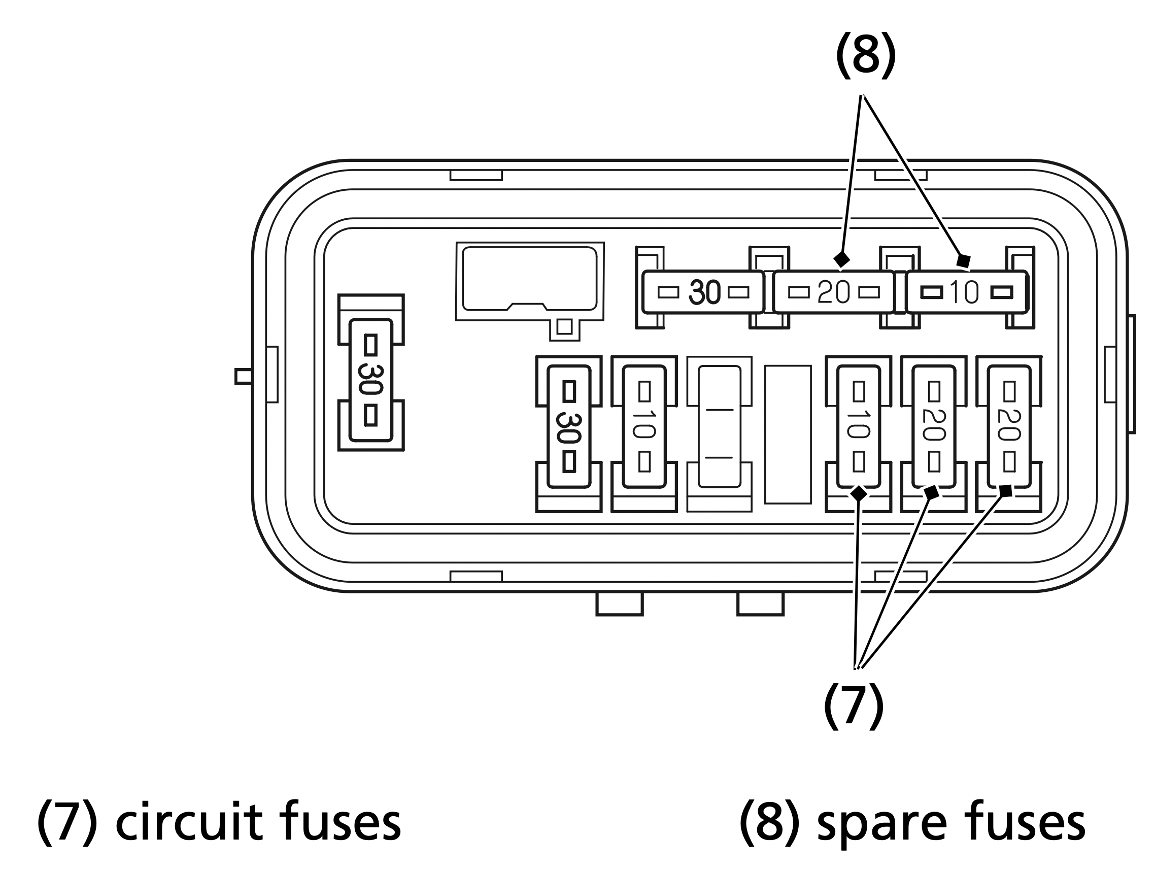
If you do not have a spare fuse and you cannot ride the ATV without fixing the problem, take a fuse of the same rating or a lower rating from one of the other circuits that you can do without temporarily.
If you replace a blown fuse with a spare fuse that has a lower rating, replace the fuse with the correct rating as soon as you can. Also remember to replace any spare fuses that were installed.
If the replacement fuse of the same rating burns out in a short time, there is probably a serious electrical problem on your ATV. Leave the blown fuse in that circuit and have your ATV checked by your dealer.
Personal safety is your first priority after a crash. If you or anyone else has been injured, take time to assess the severity of the injuries and whether it is safe to continue riding. If you cannot ride safely, send someone for help. Do not ride if you will risk further injury.
If you decide you are capable of riding safely, carefully inspect your ATV for damage and determine if it is safe to ride. Check the tightness of critical nuts and bolts securing such parts as the handlebar, control levers, brakes, and wheels.
If there is minor damage, or you are unsure about possible damage but decide to try riding the ATV back to your base, ride slowly and cautiously.
Sometimes, crash damage is hidden or not immediately apparent. When you get home, thoroughly check your ATV and correct any problems you find. Also, be sure to have your dealer check the frame and suspension after any serious crash.
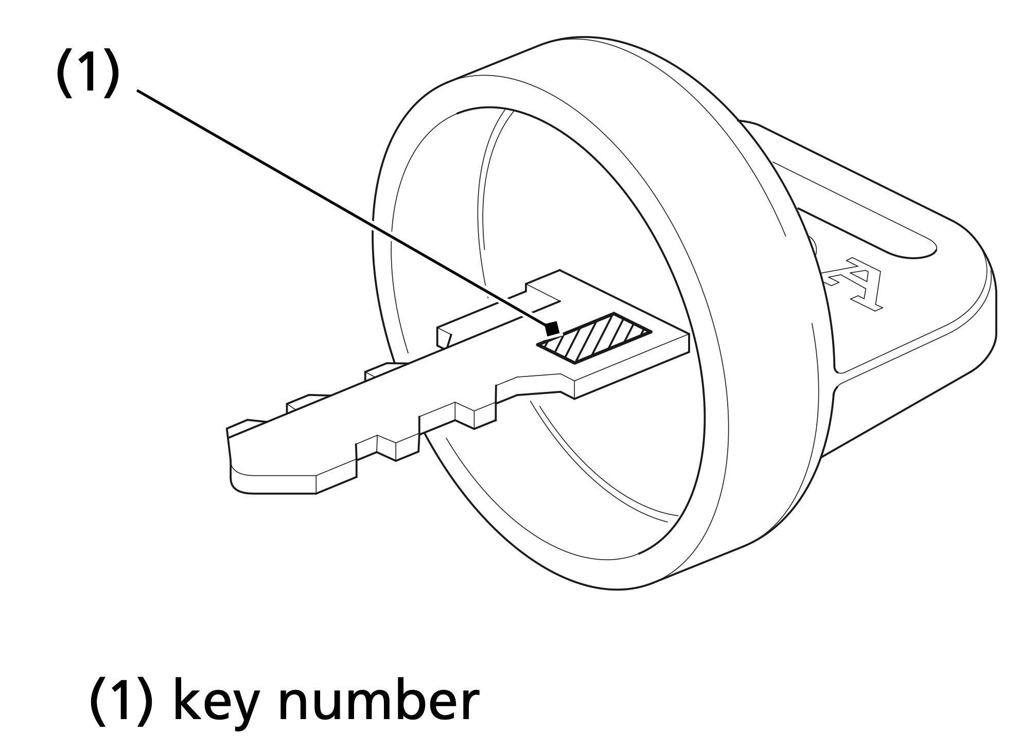
Be sure to record your key number (1). Store the spare key and recorded key number in a safe location. You’ll need this number to have a duplicate key made.
If you lose your key and aren’t carrying a duplicate, either get your spare or have one made. If you don’t know your key number, call the dealer where you purchased your Honda ATV. They may have it listed in their records. If they don’t, transport your ATV to them or the nearest dealer. The dealer will probably have to remove the ignition switch assembly to find the key number so they can make a key for you.
Jump starting is not recommended, especially if you use an automobile battery. The greater amperage of an automobile battery when the car engine is running can damage your ATV’s electrical system.
Bump starting is also not recommended.
If you can’t charge the battery or it appears unable to hold a charge, contact your dealer.
The brake levers or pedal, control cables, and other components can be damaged as you ride in dense brush or over rocky terrain. Making a trailside repair depends on how serious the damage is and what tools and supplies you have with you.
Reference file: Honda 2022 TRX420TE1 FOURTRAX RANCHER Scooter
Additionally, the document applies to other Honda models: TRX420TE1, TRX420FE1