Loading ...
Loading ...
Loading ...
Place the mounting plate against the wall and
insert the toggle wings into the holes in the wall
to mount the plate.
NOTE: Before tightening toggle bolts and wood
screw, make sure the bottom of the mounting plate
touch the bottom of the cabinet when pushed
flush against the wall and that the plate is properly
centered under the cabinet.
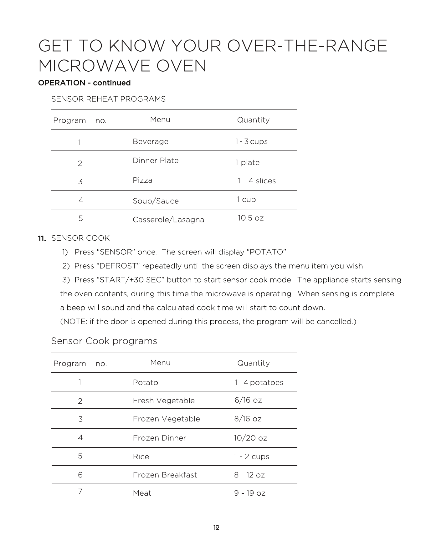
CAUTION: Be careful to avoid pinching fingers
between the back of the mounting plate and the wall.
Tighten all bolts. Pull the plate away from the wall
to help tighten the bolts.
3
4
ATTACH THE MOUNTING
PLATE TO THE WALL
A1.
Attach the plate to the wall using toggle bolts.
At least one wood screw must be used to attach
the plate to a wall stud.
Remove the toggle wings from the bolts.
Insert the bolts into the mounting plate
through the holes designated to go into drywall
and reattach the toggle wings to
3
»4Ǝ (19 mm) onto
each bolt.
1
INSTALLATION OVERVIEW
A1. Attach Mounting Plate to Wall
A2. Prepare Top Cabinet
Mount Microwave Oven
A5.
Adjust Exhaust Adaptor
A6.
Wall
Mounting
Plate
Spacing for Toggles
More Than Wall
Thickness
Bolt End
Toggle
Bolt
Toggle Wings
To use toggle bolts:
Installation Instructions
2
OUTSIDE TOP EXHAUST
(Vertical Duct)
A
IMPORTANT NOTES:
• Make sure the screws for the
blower motor and blower plate
are securely tightened when
they are reinstalled. This will
help to prevent excessive
vibration.
• Make sure the motor wiring has
been properly routed and secured,
and that the wires are not pinched.
A7. Connect Ductwork
A3.
A4.
Check Damper Operation
Adapting Microwave Blower for
Outside Top Exhaus
t
12
3
/
8"
T
O
EDG
E
NOTE: IT IS VERY
I
MPO
R
TANT
T
O
READ
A
N
D FO
LLO
W
T
H
E
D
I
RECTI
O
N
S
IN THE INSTALLA
T
ION INSTRU
CTI
O
N
S
BE
F
O
RE PR
O
CEEDING
WITH T
H
I
S
REAR
W
A
LL TEM
PLA
TE
.
Th
i
s
R
e
a
r
Wa
ll
Te
mp
l
a
te se
r
v
e
s t
o
p
o
s
it
ion
th
e
b
o
t
t
o
m
mount
ing
pla
te
a
nd
to lo
c
a
t
e
t
h
e hor
i
z
ont
a
l
e
x
h
au
s
t
ou
t
let.
1
.
Us
e
a
l
e
v
el
to
ch
e
c
k
t
h
at
t
he
t
e
m
pla
te
i
s
p
o
s
it
ioned
a
c
cu
r
ately
.
2. L
oc
at
e
and
m
a
r
k
a
t
l
e
a
s
t o
n
e
s
tu
d
o
n th
e
l
ef
t
o
r
r
ight
sid
e
of th
e
c
e
n
te
rl
i
n
e
.
It
is
i
mp
o
rt
a
n
t to u
s
e
a
t le
as
t
one
wood
s
c
r
e
w mo
unted
fi
r
mly
i
n
a stud
to su
pp
or
t
t
he
w
eigh
t
ofthe
mi
c
row
a
v
e.
M
a
r
k
t
w
o
a
d
diti
on
a
l,
e
v
e
n
l
y
s
p
a
c
ed
l
o
c
a
t
io
n
s
f
o
r
t
h
e
supp
l
ied t
o
g
gle bol
t
s
.
3. Dr
i
ll
ho
l
e
s
in
th
e
m
ar
k
e
d lo
c
atio
n
s
.
Wher
e th
er
e i
s
a
s
tu
d,
dr
il
l
a
3/
1
6"
h
o
l
e
f
o
r
woo
d sc
r
ew
s
.
F
o
r
h
o
les
that
do
n
o
t line
up
w
ith
a
s
tu
d,
d
r
il
l
5
/8"
ho
les
f
o
r
to
gg
l
e
bolts
.
DO
N
OT
I
N
S
T
AL
L
T
HE
MO
U
N
TI
N
G
P
L
AT
E
A
T
T
HIS
T
IME.
4
. Re
mov
e
t
h
e
t
e
mpla
t
e
fr
o
m
th
e
r
ea
r
w
a
l
l.
5.
Re
v
i
e
w
t
h
e In
s
tal
l
a
ti
o
n
I
n
s
t
r
uctio
n
b
o
ok
for
y
o
u
r
i
n
s
tal
l
ati
o
n situa
t
i
on
.
L
ocate
a
n
d m
ar
k
holes
to ali
gn with hole
s
in t
he
mountingp
l
ate.
I
MP
O
RTANT
:
LO
C
A
T
E
AT
LEAST
O
N
E
STU
D O
N EI
T
HER
SI
D
E
O
F
TH
E
CENT
E
R
LI
N
E
.
M
ARK
T
HE LO
CATIO
N
F
O
R 2 ADDIT
I
O
NAL, EV
EN
L
Y
SP
ACE
D TO
GGLE
BO
LTS
IN
THE MO
U
N
T
ING
P
LATE
AREA
.
Locate and mar
k
holes
to
a
l
i
g
n
w
i
th
holes
in t
he
mounting
p
l
a
te.
IMP
ORTANT
:
L
O
C
A
T
E
AT LEA
ST O
N
E
STUD
O
N E
I
THER SI
D
E
O
F
TH
E
CENT
E
R
LI
N
E
.
MARK
T
HE LO
CATIO
N
F
O
R 2 ADDITION
A
L, EV
ENLY
SP
AC
E
DTOG
GLE BO
LT
S IN
THE MO
UN
TING
PLATE
AREA
.
Tri
m the r
e
ar
wall tem
pl
at
e alo
ng
the dott
ed
line.
Trim th
e
rear
wal
l
t
em
pla
t
e
along
th
e do
t
ted lin
e.
12"
4"
Da
r
l
e
v
ue
lt
a
a
la
h
o
j
a
pa
r
a
c
o
ns
u
l
t
a
r
l
a
v
e
r
s
i
ón
e
n
E
s
pa
ñ
o
l.
24"
Loading ...
Loading ...
Loading ...