E 1
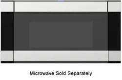
30" EXTENSION KIT: SKMD30E3DS
INSTALLATION INSTRUCTIONS
IMPORTANT NOTES TO THE INSTALLER
• Read all of the Installation Manual that is included with the Microwave Drawer before installing the extension kit.
• Observe all governing codes, ordinances, and safety instructions.
• Be sure to leave these instructions with the consumer.
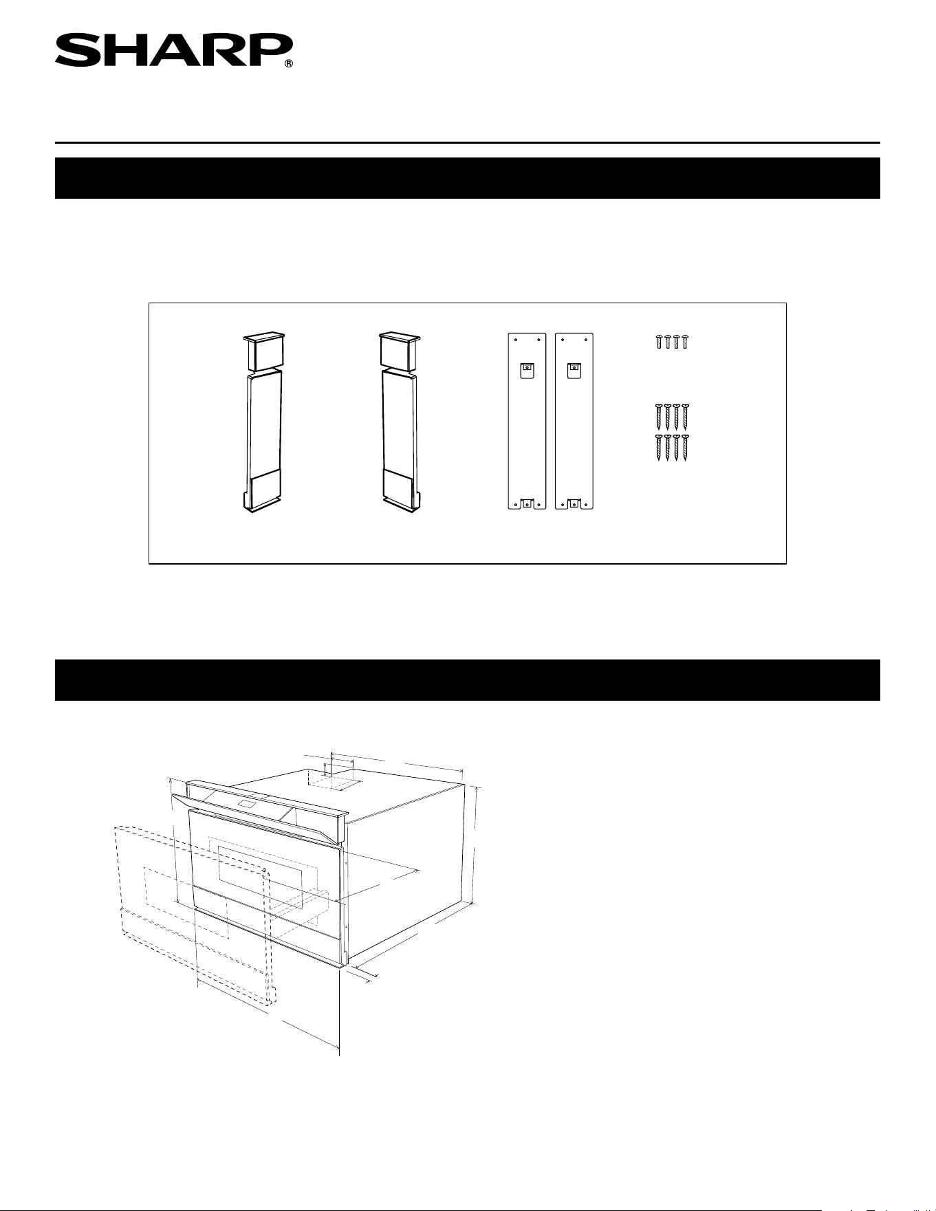
Parts included:
Left Side Trim (qty. 1)
GWAKPB282MRF0
Right Side Trim (qty. 1)
GWAKPB283MRF0
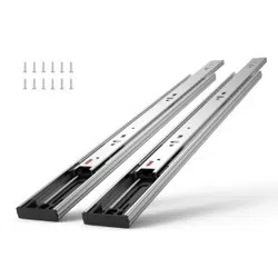
Mounting Brackets (qty. 2)
LBRC-B029MRT0
Bracket Screws (qty. 8)
LX-CZB073MRE0
Trim Screws (qty. 4)
XOTS740PO8000
Install the extension kit after properly installing the microwave drawer in the cabinet. See steps below.
Note that the side trims are marked "L" and "R" on the back side.
TINSKB263MRR0
MICROWAVE DRAWER STANDARD MOUNT, MEASUREMENTS AND INSTALLATION INSTRUCTIONS
D
G
A
B
C
J
H
I
F
E
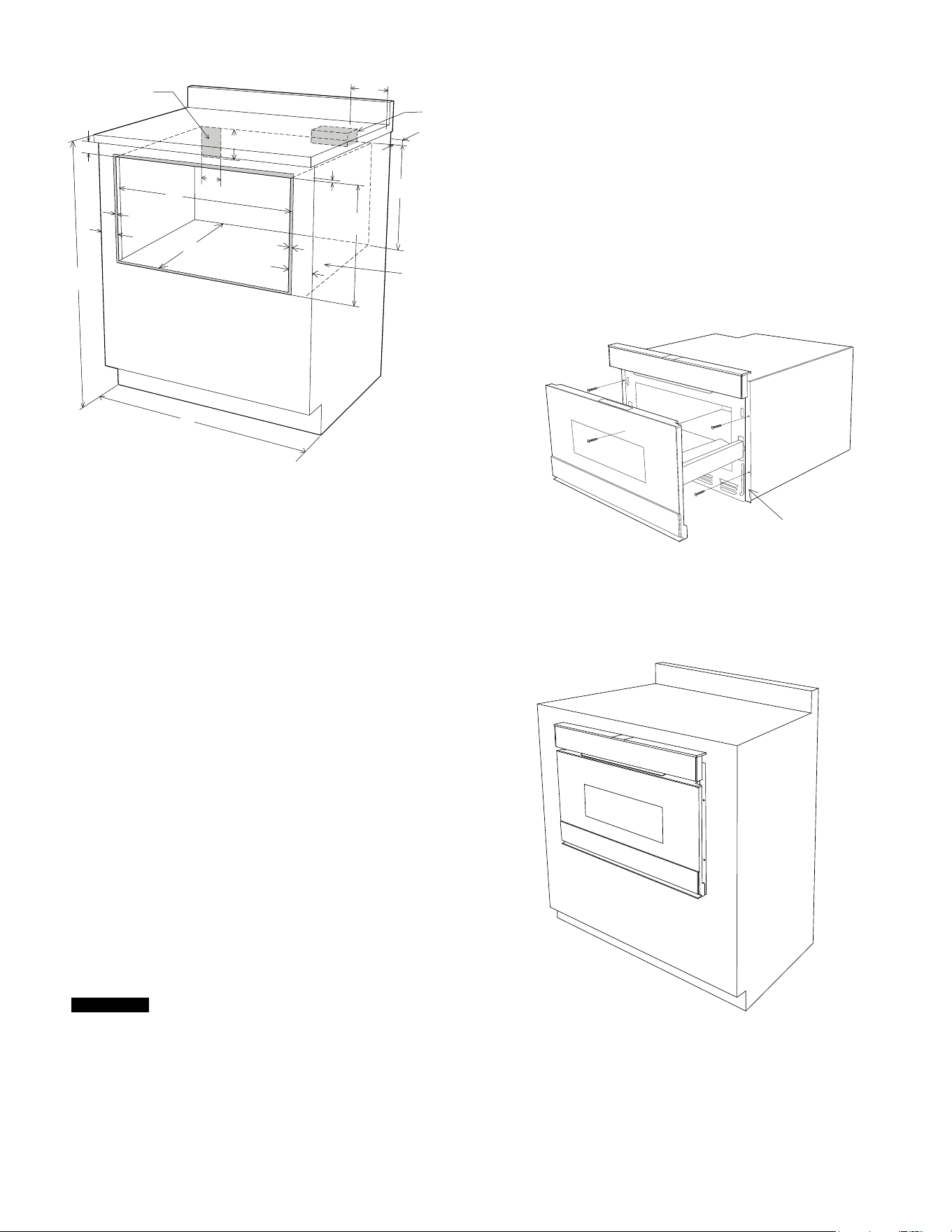
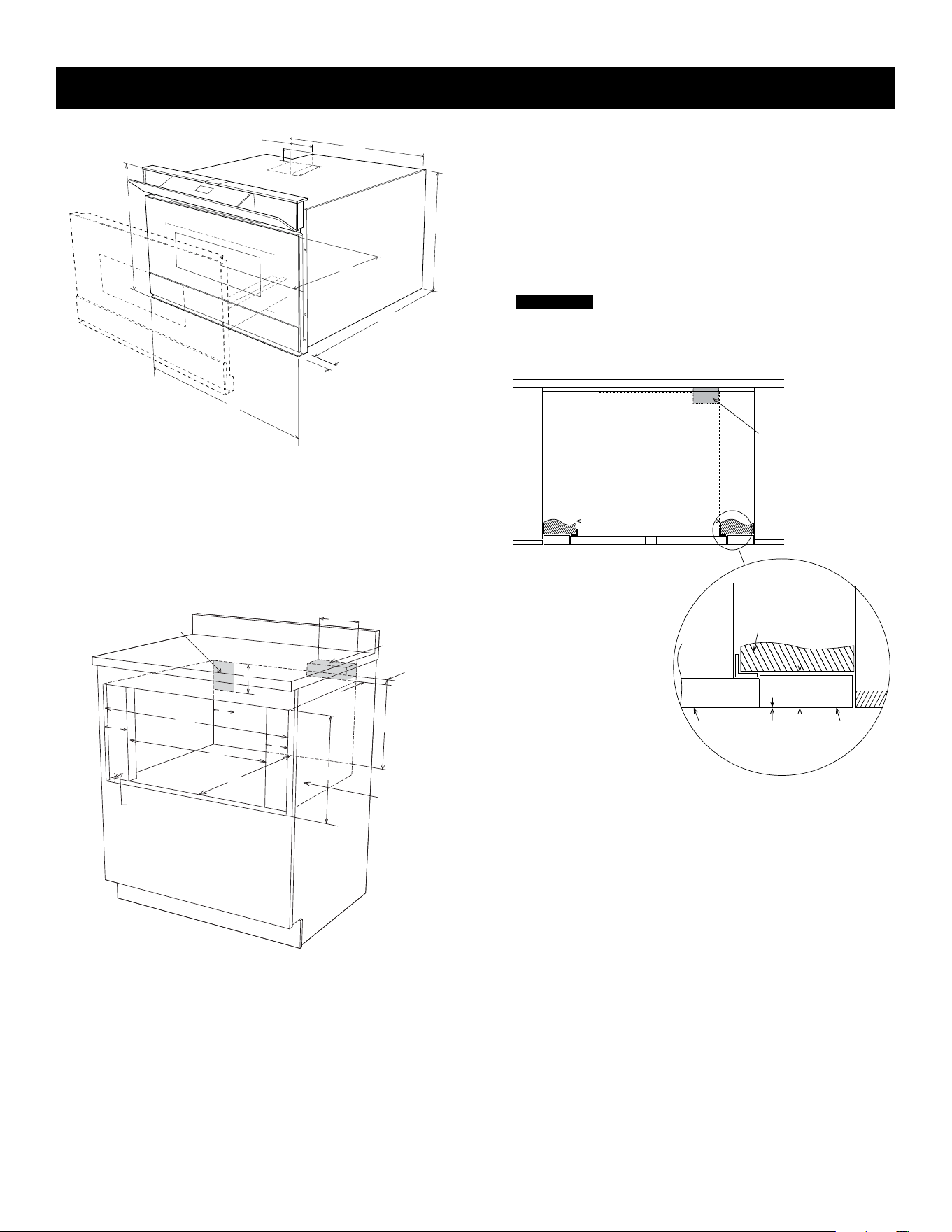
A. 21-5/8" (549.3 mm)
B. 4-11/16" (119.1 mm)
C. 1-3/4" (44.5 mm)
D. 21-7/8" (555.6 mm)
E. 23-5/8" (600.1 mm)
F. 16" (406.4 mm)
G. 14-19/32" (370.7 mm)
H. 1-17/32" (38.9 mm) door thickness
I. 15" (381.0 mm) auto drawer opening
J. 4" (101.0 mm)
Figure 1
E 2
1. Prepare cabinet opening as shown in Figure 2.
2. Place the drawer adjacent to the wall or cabinet opening. Plug
the power supply cord into the electrical outlet.
3. Carefully guide the drawer into the prepared opening. Avoid
contact with the sides of the cutout opening and also pinching
the cord between the oven and the wall.
4. Slidethedrawerallthewaybackuntilthesiderailsareush
with the face of the cabinet.
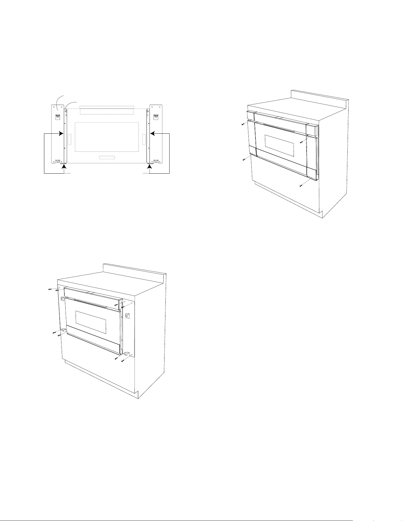
5. Open the drawer. Using the 4 holes on the drawer as a template,
pre-drill the cabinet using a 1/16” (1.6 mm) bit. Secure the
drawer with the 4 screws supplied. See Figure 3.
Figure 3
Figure 4
Side
Rail
6. Close drawer to complete oven installation. See Figure 4.
Figure 2
A. 6" (152.4 mm)
B. Suggested electrical outlet location*
C. Anti-Tip block
D. 5" (127.0 mm)
E. 3-1/2" (88.9 mm)
F. 4" (101.6 mm)
G. 22-1/8" (562.0 mm) opening
H. 14-13/16" (376.2 mm) to bottom of Anti-Tip block
I. Allow 7/8" (22.2 mm) overlap
J. 23-1/2" (596.9 mm) minimum depth
K. Allow 7/16" (11.1 mm) overlap
L. 36" (914.4 mm) countertop height
M. Allow 7/16" (11.1 mm) minimum space
N. Floor must support 100 lb (45.4 kg)
O. Allow 4-1/8" (104.4 mm) minimum space
P. 15-9/16" (395.3 mm) opening
Q. 30" (762.0 mm) minimum width
B
C
D
E
F
G
H
I
I
O
J
K
L
Q
M
N
P
A
O
Figures 1 and 2 contain many Microwave Drawer measurements
for reference when planning the drawer’s location.
This Microwave Drawer can be installed below any electric or
gas wall oven.
* Can also be installed using an electrical outlet in an adjacent cabinet
within the area where the provided electrical cord can reach. Power
cord access hole in cabinet should be a minimum 1-1/2" diameter
hole and deburred of all sharp edges.
IMP O R TANT
Always allow sufcient power cord length to the
electrical outlet to prevent tension.
Always check electrical codes for requirements.
E 3
7. Remove the 2 trim screws from each mounting bracket to
begin installation.
Note: The mounting brackets come assembled to the side
trims.
8. Open the drawer to properly align brackets to microwave side
rails. See Figure 5.
Bracket
Side rails
Align sides and bottom of the 30"
mounting brackets to the sides and bottom
of the microwave drawer side rails
Figure 5
9. Using the 4 holes on each bracket as a template, pre-drill
the cabinet using a 1/16" (1.6 mm) bit. Secure the mounting
brackets to cabinet with the 8 bracket crews provided. See
Figure 6.
Figure 6
10. Place side trims on top of the mounting brackets, aligning the
screw holes.
Note: Each side trim is marked "L" and "R" on the backside
to indicate Left and Right.
11. Mount the Left and Right 30" trim extensions using the 4 trim
screws provided. See Figure 7.
4
Figure 7
E 4
C
L
Top view
A
Anti-Tip block
Mounting cleat
B
C
Drawer face
Trim
face
Note: the mounting surface
of the finished cleat must sit
1-17/32”
(38.9 mm) back from
the face of the cabinet.
**
MICROWAVE DRAWER FLUSH MOUNT, MEASUREMENTS AND INSTALLATION INSTRUCTIONS
Figure 2
1. Prepare cabinet opening as shown in Figure 2.
C
L
H
E
F
D
N
N
A
B
J
I
M
K
G
I
I
A. 6" (152.4 mm)
B. Suggested electrical outlet
location*
C. Anti-Tip block
D. 5" (127.0 mm)
E. 3-1/2" (88.9 mm)
F. 4" (101.6 mm)
G. 30-5/16" (769.9 mm) min
30-5/8" (777.9 mm) max
H. 14-13/16" (376.2 mm) to bottom
of Anti-Tip block
I. 1-17/32" (38.9 mm) Refer to
Figure 3 **
J. 23-1/2" (596.9 mm) minimum
depth
K. 22-1/8" (562.0 mm)
L. Floor must support 100 lb (45.4
kg)
M. 16-1/4" (412.8 mm) opening
* See Figure 4C for detail
N. Allow 4-1/8" (104.4 mm)
D
G
A
B
C
J
H
I
F
E
Figures 1 and 2 contain many Microwave Drawer measurements
for reference when planning the drawer’s location.
This Microwave Drawer can be installed below any electric or
gas wall oven.
* Can also be installed using an electrical outlet in an adjacent cabinet
within the area where the provided electrical cord can reach. Power
cord access hole in cabinet should be a minimum 1-1/2" diameter
hole and deburred of all sharp edges.
IMP O R TANT
Always allow sufcient power cord length to the
electrical outlet to prevent tension.
Always check electrical codes for requirements
A. 21-5/8" (549.3 mm)
B. 4-11/16" (119.1 mm)
C. 1-3/4" (44.5 mm)
D. 21-7/8" (555.6 mm)
E. 23-5/8" (600.1 mm)
F. 16" (406.4 mm)
G. 14-19/32" (370.7 mm)
H. 1-17/32" (38.9 mm) door thickness
I. 15" (381.0 mm) auto drawer opening
J. 4" (101.0 mm)
Figure 1
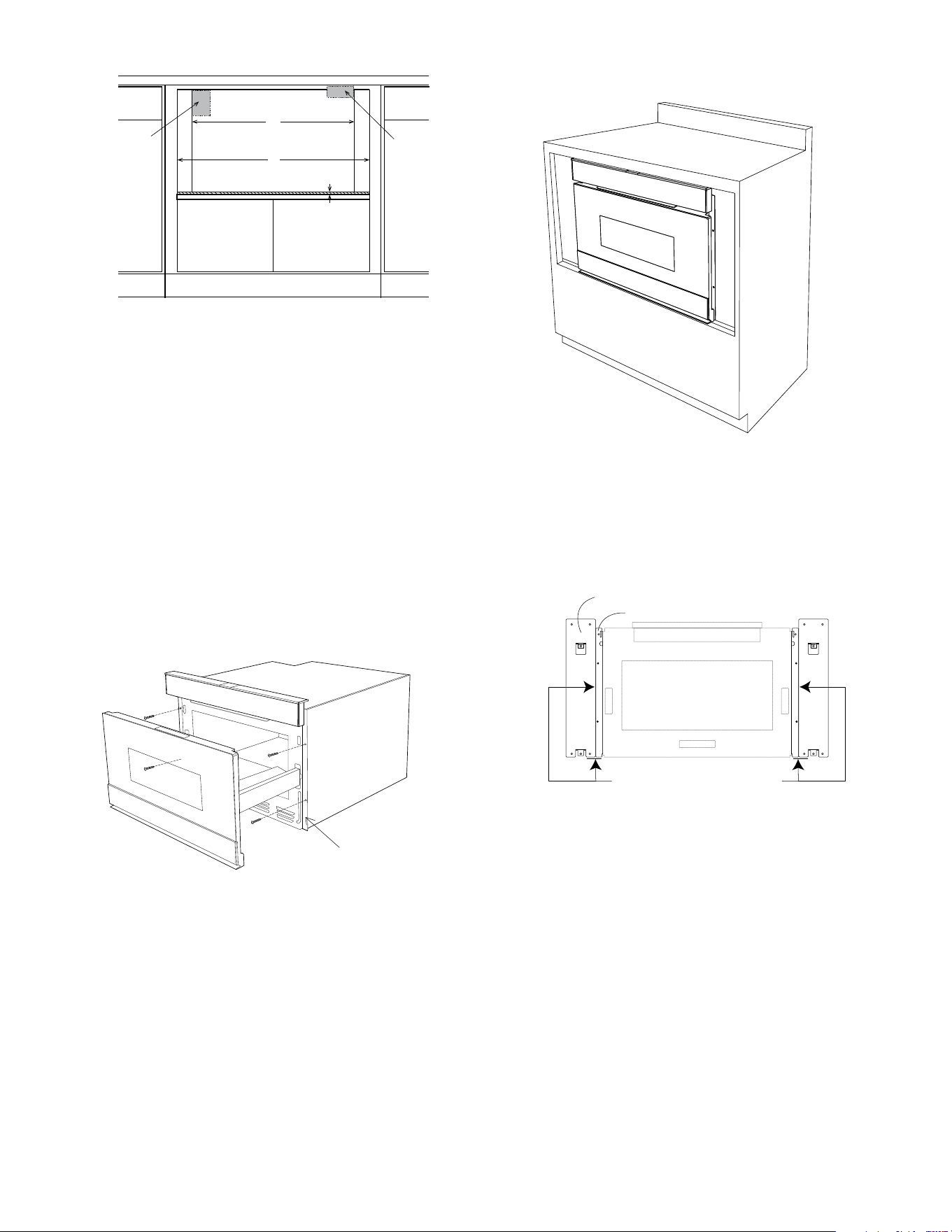
Figure 3
A. 22-1/8" (596.9 mm) mounting cleat opening width
B. 0"ush
C. 1-17/32" (38.9 mm) front of cleat to cabinet face
Note: For pre-existing 30” cabinet openings that desire a standard
mount,llerpanelswillneedtobeinstalledoneithersideofthecut
out to properly mount the extension kit panels.
E 5
7. Remove the 2 trim screws from each mounting bracket to
begin installation.
Note: The mounting brackets come assembled to the side
trims.
8. Properly align brackets to microwave side rails. See Figure 7.
Bracket
Side rails
Align sides and bottom of the 30"
mounting brackets to the sides and bottom
of the microwave drawer side rails
Figure 7
Figure 4
A. 22-1/8" (562.0 mm) mounting cleat opening width
B. 30-5/16" (770.0 mm) minimum
30-5/8" (777.9 mm) maximum
C. 1/8" (3.2 mm) from opening to top of shelf
2. Place the drawer adjacent to the wall or cabinet opening. Plug
the power supply cord into the electrical outlet.
3. Carefully guide the drawer into the prepared opening. Avoid
contact with the sides of the cutout opening and also pinching
the cord between the oven and the wall.
4. Slide the drawer all the way back until the side rails touch the
cleats mounted in the cabinet opening.
5. Open the drawer. Using the 4 holes on the drawer as a template,
pre-drill the cabinet using a 1/16” (1.6 mm) bit. Secure the
drawer with the 4 screws supplied. See Figure 5.
C
Front view
No oven shown
B
A
Suggested electrical
outlet location
Anti-Tip block
Figure 5
Figure 6
Side
Rail
6. Close drawer to complete oven installation. See Figure 6.
E 6
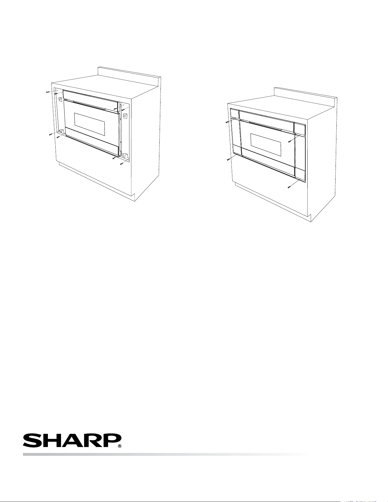
9. Using the 4 holes on each bracket as a template, pre-drill
the cabinet using a 1/16" (1.6 mm) bit. Secure the mounting
brackets to cabinet with the 8 bracket screws provided. See
Figure 8.
Figure 8
100 Paragon Drive, Suite #100, Montvale, NJ 07645, USA • 1-800-BE-SHARP (237-4277)
335 Britannia Road East, Mississauga, Ontario, L4Z 1W9, Canada
10. Place side trims on top of the mounting brackets, aligning
the screw holes.
Note: Each side trim is marked "L" and "R" on the backside
to indicate Left and Right.
11. Mount the Left and Right 30" trim extensions, using the 4
trim screws provided. See Figure 9.
Figure 9