Write the model and serial
numbers here:
Model # _________________
Serial # _________________
You can find them on the rating
label on the right side of your
water heater.
GE is a trademark of the General Electric Company. Manufactured under trademark license.
WATER HEATER
GeoSpring
TM
Solar
49-6000121 Rev. 0 05-19 GEA
GT50C10BAM
GT40C10BAM
GT25C10BAM
SAFETY INFORMATION .........3
OPERATING INSTRUCTIONS
Sizing information .....................5
CARE AND CLEANING .......... 11
INSTALLATION
INSTRUCTIONS ..................13
TROUBLESHOOTING TIPS ..... 36
REPLACEMENT PARTS .........37
CERTIFICATION .................38
LIMITED WARRANTY .......... 46
CONSUMER SUPPORT ......... 48
FRANÇAIS
Pour une version français de
ce manuel d’utilisation, veuillez
visiter notre site web à l’adresse
GEAppliances.com.
ESPAÑOL
Para consultar una version en
español de ests manual de
instrucciones, visite nuestro sitio
de internet GEAppliances.com
OWNER’S MANUAL
AND INSTALLATION
INSTRUCTIONS
2 49-6000121 Rev. 0
THANK YOU FOR MAKING GE APPLIANCES A PART OF YOUR HOME.
Whether you grew up with GE Appliances, or this is your first, we’re happy to have you in the family.
We take pride in the craftsmanship, innovation and design that goes into every GE Appliances
product, and we think you will too. Among other things, registration of your appliance ensures that we
can deliver important product information and warranty details when you need them.
Register your GE appliance now online. Helpful websites and phone numbers are available in the
Consumer Support section of this Owner’s Manual. You may also mail in the pre-printed registration
card included in the packing material.
49-6000121 Rev. 0 3
READ AND SAVE THESE INSTRUCTIONS
IMPORTANT SAFETY INFORMATION
READ ALL INSTRUCTIONS BEFORE USING THE APPLIANCE
SAFETY INFORMATION
WARNING
For your safety, the information in this manual must be followed to minimize the risk of fire or
explosion, electric shock, or to prevent property damage, personal injury, or loss of life.
Be sure to read and understand the entire Owner’ s Manual before attempting to install or operate this solar water
heater. It may save you time and cost. Pay particular attention to the Safety Instructions. Failure to follow these
warnings could result in serious bodily injury or death. Should you have problems understanding the instructions in
this manual, or have any questions, STOP and get help from a qualified service technician or the local electric utility.
WARNING
Risk of Fire - DO NOT store or use gasoline or other flammable vapors and liquids in the
vicinity of this or any other appliance. Keep rags and other combustibles away.
WARNING
If the water heater has been subjected to flood, fire, or physical damage, turn off power
and water to the water heater.
Do not operate the water heater again until it has been thoroughly checked by qualified service personnel.
Safety Precautions
A. Do Not turn on or remove protective glass film unless the water heater is filled with water.
B. Do Not turn on or remove protective glass film if the cold water supply shut-off valve is closed.
NOTE: Flammable vapors may be drawn by air currents from surrounding areas to the water heater.
C. If there is any difficulty in understanding or following the Operating Instructions or the Care and Cleaning
section, it is recommended that a qualified person or serviceman perform the work.
WARNING
Ɣ8VHUPXVWEHLQFRPSOLDQFHZLWKDOODSSOLFDEOH
federal, state, and municipal building and fire safety
laws, codes, and regulations. Check the unit and the
accessories for any visible defects, cracks, or other
damages after unpacking and before first use. If you
see any damage, do not use the product. Contact
customer service for help. Only operate the product
after proper and complete installation and assembly.
Ɣ$VVXUHWKDWPLQRUVXQGHUWKHDJHRIRUSHUVRQV
with reduced physical, sensory or mental abilities
do not have access to the GeoSpring Solar System.
Assure that the system is not in direct contact with
any items such as leaves, twigs, flammable materials,
cables, or other materials. Keep a safety clearance of
at least 5 feet from air conditioning systems, heaters,
satellite dishes or any other electronic devices.
Ɣ5HJXODWLRQFRPSOLDQWQRQSHUVRQDOIDOOSURWHFWLRQRU
safety netting or other catch equipment, in accordance
with Roof Covering and Roof Sealing Work and
Scaffolding Work with Safety Net, must be installed
before starting work. ASSURE COMPLIANCE
WITH ALL APPLICABLE FEDERAL, STATE,
AND MUNICIPAL SAFETY LAWS, CODES AND
REGULATIONS PERTAINING TO ROOFING
SAFETY.
Ɣ2QO\XVHVDIHW\KDUQHVVHTXLSPHQWKDUQHVVHVRU
belts, ropes and straps, fall arresters, rope shorteners)
that has been approved by authorized testing
authorities.
Ɣ'RQRWXVHGDPDJHGODGGHUVHJVSOLQWHUHGVWULQJHUV
and rungs on wooden ladders, bent or kinked
metal ladders. Do not patch up splintered or broken
stringers, steps and rungs of wooden ladders.
Ɣ0DNHVXUHWKDWOHDQWRODGGHUVDUHSURSSHGVHFXUHO\
Secure lean-to ladders against slipping, falling over
and sinking into the ground e.g. by using wider feet,
adjusting the ladder feet to the ground surface,
securing/hook fixtures.
Ɣ:KHQXVLQJOHDQWRODGGHUVWKHUHLVDULVNRI
dangerous falls if the ladder sinks, slips or falls over.
Only lean ladders against secure supporting surfaces.
Cordon off ladders in traffic areas.
Ɣ2QO\WKHSUHVFULEHGOLTXLGW\SHPD\EHXVHG
Ɣ6DIHW\KDUQHVVHVPXVWEHVHFXUHGDERYHWKHXVHU
if possible. Only secure safety harnesses to building
elements or connection points with sufficient load-
bearing capacity. If no non-personal fall protection or
fall arrest system is used there is a risk of falling from
a great height which can lead to serious or fatal injury
if no safety harness or equipment is used.
4 49-6000121 Rev. 0
SAFETY INFORMATION
IMPORTANT SAFETY INFORMATION
READ ALL INSTRUCTIONS BEFORE USING THE APPLIANCE
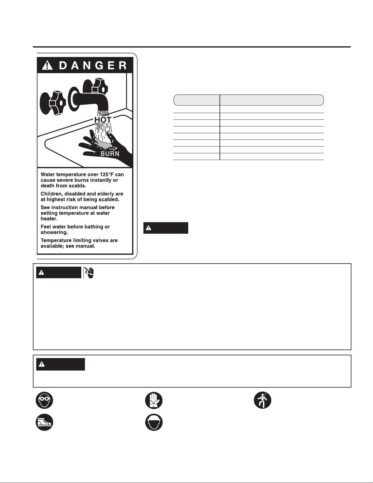
WATER TEMPERATURE ADJUSTMENT
:DWHUWHPSHUDWXUHVDERYH)FDQFDXVHVHYHUHEXUQVRUGHDWKIURP
scalding. Be sure to read and follow the warnings outlined on the label
pictured.
Mixing valves are required for the GeoSpring Solar System. They are used
to reduce water temperature by mixing hot and cold water in branch water
lines. Contact a licensed plumber or the local plumbing authority for further
information.
The chart shown above may be used as a guide in determining the proper
water temperature for your home.
DANGER
There is a Hot Water SCALD Potential if the mixing
valve control temperature is set too high. Households with small
children, disabled or elderly persons may require a 120°F (49°C) or
lower thermostat setting to prevent contact with “HOT” water.
Time/Temperature Relationship in Scalds
Temperature Time to Produce a Serious Burn
)& 0RUHWKDQPLQXWHV
)& WRPLQXWHV
)& $ERXWVHFRQGV
)& $ERXWVHFRQGV
)& /HVVWKDQVHFRQGV
)& /HVVWKDQVHFRQGV
)& $ERXWVHFRQGV
)& $ERXWVHFRQG
Table courtesy of Shriners Burn Institute
CAUTION
The GeoSpring Solar System and its pipes and accessories can reach temperatures of up to
)'RQRWWRXFKDQ\SDUWVRIWKHV\VWHPLWVSLSHVRULWVDFFHVVRULHVGXULQJRSHUDWLRQRUZKHQLWLVH[SRVHGWR
sunlight.
WARNING
ELECTRICAL SHOCK HAZARD
Contact with live overhead electrical cables and wiring
can lead to mortal injury.
Work in the vicinity of live, electrical cables and wiring,
where contact is possible, can only be carried out if:
Ɣ they are voltage-free and it is ensured that they remain
so for the duration of the work to be carried out
Ɣ the live elements are secured by being covered up or
cordoned off
Ɣ safety distances are observed
Voltage radius
3.5 ft .....XSWR9
IW .......9WR9
IW ......9WR9
IW ......9WR9
!IWLIWKHYROWDJHLVQRWNQRZQ
READ AND SAVE THESE INSTRUCTIONS
Wear protective goggles when
drilling or handling collectors
If no non-personal fall
protection or fall arrest
system or equipment has
been installed for technical
reasons, safety harnesses
must be worn.
Wear cut-proof safety gloves
when carrying out installation
work or handling collectors.
Wear safety shoes when
carrying out installation work
Wear a helmet when carrying
out installation work.
49-6000121 Rev. 0 5
IMPORTANT SAFETY INFORMATION
READ ALL INSTRUCTIONS BEFORE USING THE APPLIANCE
Water Heater Sizing Information
Mixing Valves - Water Heater Capacity and Increasing Temperature Setpoint:
Mixing valves for reducing point-of-use water
temperature by mixing hot and cold water in branch
water lines are commercially available. Contact a
licensed plumber or the local plumbing authority for
further information.
The water heater temperature setting strongly impacts
the amount of usable hot water available for showers
and baths.
• Energy consumption/savings and efficiency testing
of water heaters, including the GeoSpring™ Solar, is
performed according to Solar Rating & Certification
&RUSRUDWLRQ65&&UHTXLUHPHQWVVSHFLILHGDWWKHGDWH
of manufacture.
• Safety regulations require a factory setting no greater
WKDQ)&IRUDOOQHZZDWHUKHDWHUV
• The user can adjust the temperature setting to meet
their needs. Always read and understand the safety
instructions contained in the owner’s manual before
adjusting the temperature setpoint.
DANGER
There is a Hot Water SCALD
Potential if the control water
temperature is set too high. Households with small
children, disabled or elderly persons may require a
120°F (49°C) or lower thermostat setting to prevent
contact with “HOT” water.
Ground Mount or Readily Accessible Areas
When a collector module is intended for installation in
areas which are readily accessible to other than service
personnel. The water heater must be guarded to protect
against unintentional contact. Contact with the solar
ZDWHUKHDWHUGXULQJXVHPD\UHVXOWLQVHYHUHEXUQV8VH
caution when servicing or performing maintenance.
OPERATING INSTRUCTIONS: Sizing Information
FOR INSTALLATIONS IN THE STATE OF CALIFORNIA
&DOLIRUQLD /DZ UHTXLUHV WKDW UHVLGHQWLDO ZDWHU KHDWHUV PXVW EH EUDFHG DQFKRUHG RU VWUDSSHG WR UHVLVW IDOOLQJ RU
KRUL]RQWDOGLVSODFHPHQWGXHWRHDUWKTXDNHPRWLRQV)RUUHVLGHQWLDOZDWHUKHDWHUVXSWRJDOORQV/FDSDFLW\
DEURFKXUHZLWKJHQHULFHDUWKTXDNHEUDFLQJLQVWUXFWLRQVFDQEHREWDLQHGIURP2IILFHRIWKH6WDWH$UFKLWHFW3
6WUHHW6DFUDPHQWR&$RU\RXPD\FDOORUDVNDZDWHUKHDWHUGHDOHU
Applicable local codes shall always govern installation. For residential water heaters of a capacity greater than 52
JDOORQV/FRQVXOWWKHORFDOEXLOGLQJMXULVGLFWLRQIRUDFFHSWDEOHEUDFLQJSURFHGXUHV
WARNING
BURN HAZARD
If installing the water heater on the ground or other areas that are accessible, the water heater must be guarded to
protect against unintentional contact.
&RQWDFWZLWKWKHVRODUZDWHUKHDWHUGXULQJXVHPD\UHVXOWLQVHYHUHEXUQV8VHFDXWLRQZKHQVHUYLFLQJRU
performing maintenance.
READ AND SAVE THESE INSTRUCTIONS
49-6000121 Rev. 0
Specifications for Water Quality
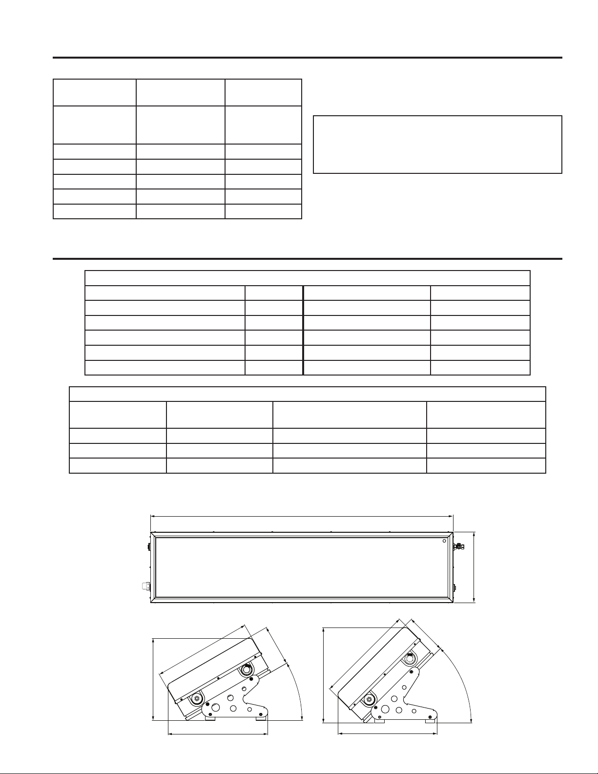
Technical Data - GeoSpring™ Solar 25
OPERATING INSTRUCTIONS: Specifications / Technical Data
WATER
SUBSTANCE
UNITS OF
MEASUREMENT
PARAMETER
pH value - XQGHU
observance of
SI Index)*
Total hardness gpg
Chlorides ppm
Free chlorine ppm
Sulfate ppm
Conductibility EC
Required Water qualities*
*under observance of SI Index
NOTICE:
*To avoid system failure and damages, assure that
the water quality falls within the range of the water
values as written in the table.
NOTICE:
Your warranty is void if you operate the GeoSpring™
Solar using water which does not fall within the
range of the water values as written in the table.
GeoSpring Solar 25
Gross area IW
2
Net area IW
2
0D[KHLJKWPRXQW ƎƎ Collector outer dimensions Ǝ[Ǝ
9ROXPHKRWZDWHUVWRUDJHWDQN 24 gal Collector/inclination
:HLJKWZLWKPRXQWQRZDWHU OEV Max. operating pressure 36,
:HLJKWZLWKPRXQWDQGZDWHU OEV Cold/hot water connections 3/4 MNPT
Thermal insulation - storage tank Ǝ /LTXLG7\SH Water
86.0"
20.0"
20.2"
20.0"
19.3"
16.6"
8.35"
20.0"
8.35"
30°
45°
20.1"
$YHUDJH3HUIRUPDQFH'DWD+LJK5DGLDWLRQ
/RFDWLRQ Climate Category *7&%$0JDOGD\DW) *7&%$0$YJ6RODU
(QHUJ\N:KGD\
Phoenix, AZ B 34
/RV$QJHOHV&$ C 2.52
San Francisco, CA C
49-6000121 Rev. 0
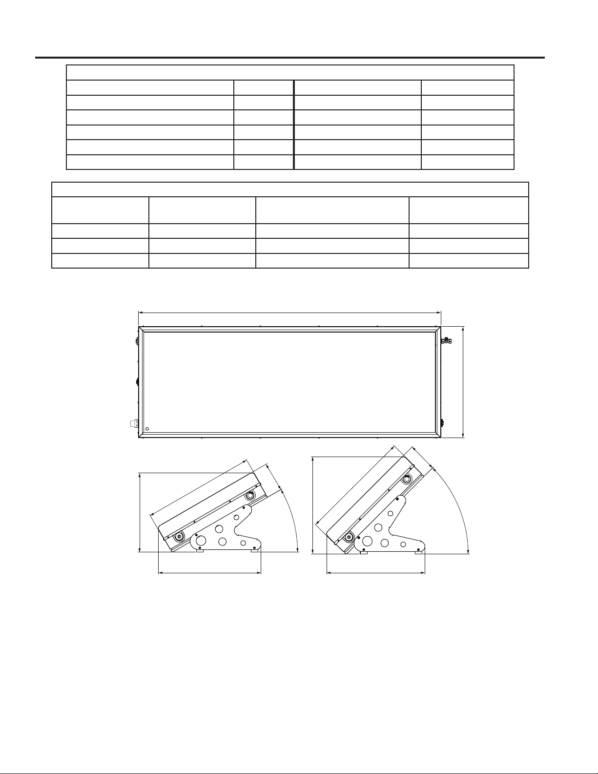
Technical Data - GeoSpring™ Solar 40
OPERATING INSTRUCTIONS: Technical Data
GeoSpring Solar 40
Gross area IW
2
Net area IW
2
0D[KHLJKWPRXQW ƎƎ Collector outer dimensions Ǝ[Ǝ
9ROXPHKRWZDWHUVWRUDJHWDQN JDO Collector/inclination
:HLJKWZLWKPRXQWQRZDWHU OEV Max. operating pressure 36,
:HLJKWZLWKPRXQWZLWKZDWHU OEV Cold/hot water connections 3/4 MNPT
Thermal insulation - storage tank Ǝ /LTXLG7\SH Water
86.0"
31.5"
29.1"
28.0"
22.4"
31.5
"
8.35"
27.6"
31.5"
8.35"
30°
45°
$YHUDJH3HUIRUPDQFH'DWD+LJK5DGLDWLRQ
/RFDWLRQ Climate Category *7&%$0JDOGD\DW) *7&%$0$YJ6RODU
(QHUJ\N:KGD\
Phoenix, AZ B
/RV$QJHOHV&$ C
San Francisco, CA C
49-6000121 Rev. 0
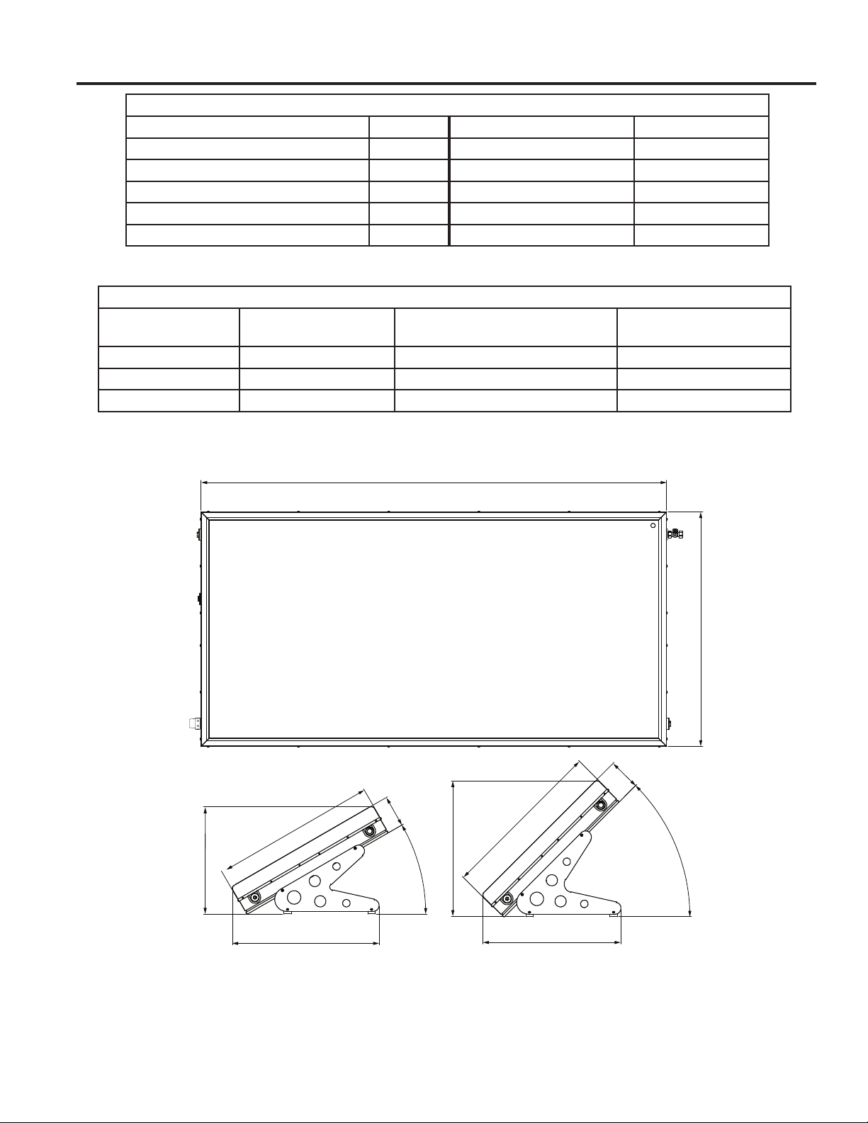
OPERATING INSTRUCTIONS: Specifications / Technical Data
Technical Data - GeoSpring™ Solar 50
GeoSpring Solar 50
Gross area IW
2
Net area 23 ft
2
0D[KHLJKWPRXQW ƎƎ Collector outer dimensions Ǝ[Ǝ
9ROXPHKRWZDWHUVWRUDJHWDQN JDO Collector/inclination
:HLJKWZLWKPRXQWQRZDWHU OEV Max. operating pressure 36,
:HLJKWZLWKPRXQWZLWKZDWHU OEV Cold/hot water connections 3/4 MNPT
Thermal insulation - storage tank Ǝ /LTXLG7\SH Water
86.0"
43.3"
38.6"
36.4"
28.3"
43.3"
8.35"
35.8"
30°
45°
8.35"
43.3"
$YHUDJH3HUIRUPDQFH'DWD+LJK5DGLDWLRQ
/RFDWLRQ Climate Category *7&%$0JDOGD\DW) *7&%$0$YJ6RODU
(QHUJ\N:KGD\
Phoenix, AZ B
/RV$QJHOHV&$ C
San Francisco, CA C
49-6000121 Rev. 0
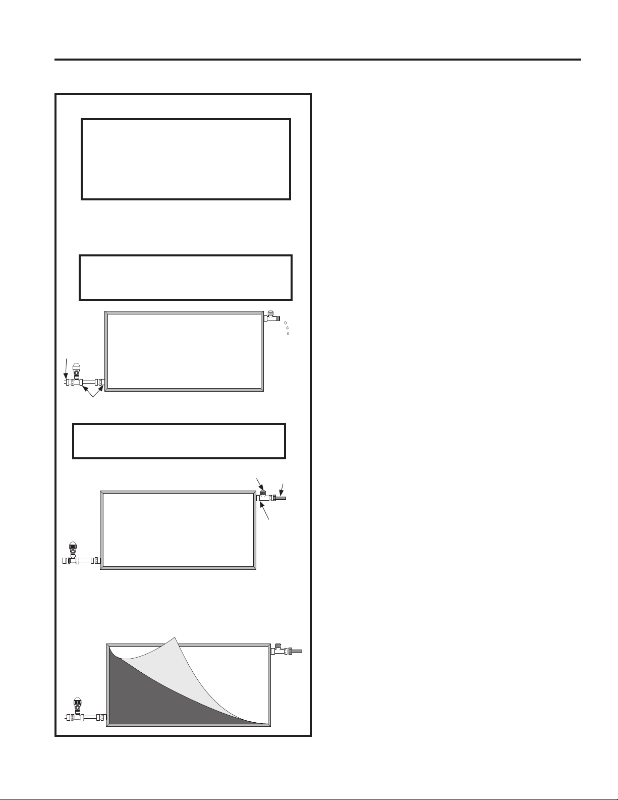
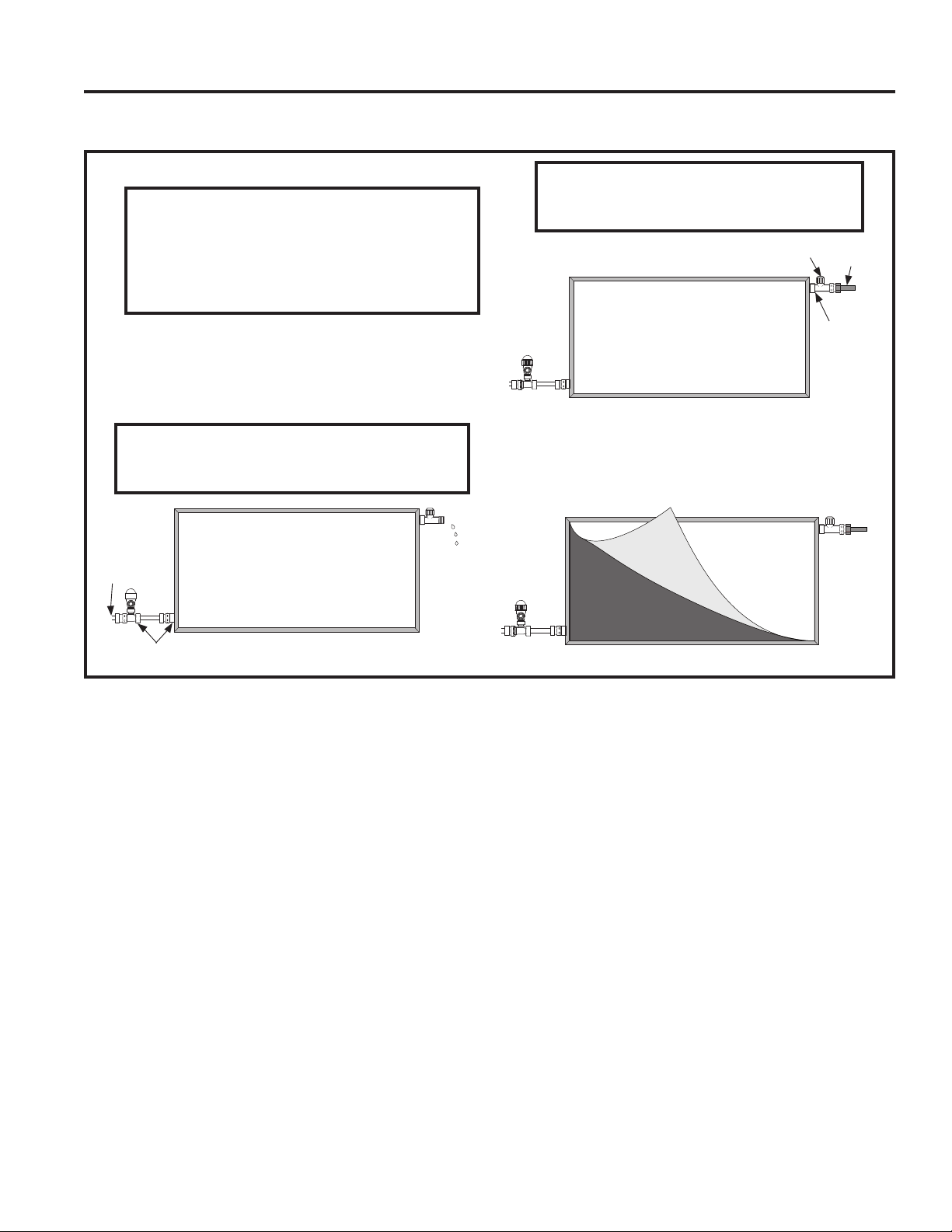
Operating and Filling Instructions
The GeoSpring Solar system is delivered with a
protective film on the solar glass. Do not remove this
film, which blocks the sunlight, until after the system
has been filled with water. Otherwise the system
components can be damaged because the unblocked
sunlight heats up the empty system which lacks water
to absorb the heat. Remove the protective film after the
system has been filled, as it serves no other purpose. It
is recommended that you fill the system within 2 weeks
after installation, otherwise residue from the film may
adhere to the solar glass. Repeat filling and flushing
until you are sure that all air has been removed from the
system. Make sure that the maximum operating pressure
stated on the rating plate or in the installation instructions
is not exceeded. Check to make sure that all safety
components have been installed in accordance with the
K\GUDXOLFGLDJUDPLQWKHFKDSWHU³+\GUDXOLF&RQQHFWLRQ´
in this manual) before you open the water supply, fill the
system, and initialize start-up.
,ISRVVLEOHILOOWKHFROOHFWRULQWKHPRUQLQJEHIRUHVXQ
light heats up the absorber.
2. It is recommended that you fill the collector before
you connect the return piping to the collector
outlet. Make sure that the system is vented to the
atmosphere. Failure to follow these instructions could
void the warranty and damage the system.
3. Close the cold water shut-off valve. Set the flow
control valves to the solar pre-heat position. Consult
system valve position drawings. Close the water
heater drain on the supply side to the solar loop
piping. Open the water heater drain on the return
side.
4. Open the cold water shut-off valve to fill the collector.
Allow the air to be purged from the system through
the open water heater drain on the return side of the
solar loop piping.
5. Allow water to flow from the system for several
minutes to flush out the collector and the piping.
&ORVHWKHRSHQZDWHUKHDWHUGUDLQ&DUHIXOO\LQVSHFW
the system for leaks.
7XUQRQDKRWZDWHUIDXFHWLQWKHKRXVHWRSXUJHDQ\
remaining air from the system.
0DNHVXUHDOO65&&DQGPDQXIDFWXUHUUHTXLUHGODEHOV
are placed on the system. Consult SRCC appendix for
required labels and their placements.
3ODFHLQVWDOOHUODEHORQWKHDX[LOLDU\ZDWHUKHDWHU
)ROORZWKLVPDQXDOIRUDGGLWLRQDOLQVWDOODWLRQDQG
operation instructions.
To Fill the Water Heater
NOTICE:
Risk of Unit Damage - The tank must be full of
water before removing the film and turning on.
The water heater warranty does not cover damage
or failure resulting from operation with an empty
or partially empty tank.
9HQWWRDWPRVSKHUHEHIRUHDQGZKLOHILOOLQJ
Open the shut-off valve in the cold water supply line.
Open each hot water faucet slowly to allow the air to vent
from the water heater and piping.
$VWHDG\IORZRIZDWHUIURPWKHKRWZDWHUIDXFHWVLQGLFDWHV
a full water heater.
OPERATING INSTRUCTIONS
Operating Instructions
General
7KH/LPLWHG:DUUDQW\LVYRLGLI\RXGRQRWGUDLQDQG
cover the GeoSpring Solar under the temperature
conditions described in this manual. Appropriate
insulation or pipe heat tracing must be provided on-site to
prevent hot and cold water pipes from freezing. A mixing
valve, at which the required water temperature can be
set, must always be installed at the hot water outlet.
NOTICE:
If the temperature falls below 32°F for 8
consecutive hours, the GeoSpring Solar system
must be drained and covered. The water heater
warranty does not cover damage or failure
resulting from freezing.
The combined non-return/safety valve provided
must be installed at the cold water connection of the
GeoSpring Solar system to limit positive pressure in
the water circuit. The freeze tolerance limits are based
upon an assumed set of environmental conditions.
Extended periods of cold weather, including ambient
air temperatures below the specified limit, may cause
freezing in exposed parts of the system. It is the owner’s
responsibility to protect the GeoSpring Solar system in
accordance with the manufacturer’s instructions if the
air temperature is anticipated to approach the specified
freeze tolerance limits.
49-6000121 Rev. 0
OPERATING INSTRUCTIONS
Operating Instructions
Operation
If the homeowner cannot get water to flow from the hot
water lines, check all shut off valves and ensure the
combined non-return/safety valve has been installed
correctly, as it has an integrated check valve. To
determine whether the GeoSpring Solar system is
working, measure the water temperature returning from
the system on a sunny day. The output temperature
should be warmer than the input temperature.
WARNING
BURN HAZARD
Do NOT touch water heater pipes or surfaces,
which can be hot. Failure to follow these
instructions can result in severe burns.
Increasing Efficiency
To increase the efficiency of the GeoSpring Solar
system:
Ɣ,ISRVVLEOHXVHKRWZDWHULQWKHHYHQLQJ)RUH[DPSOH
take showers in the evening rather than during the
day.
Ɣ7KHSHUIRUPDQFHRIWKH*HR6SULQJ6RODUV\VWHP
in the Northern Hemisphere is optimized when it is
mounted facing true south. Performance, however,
VXIIHUVYHU\OLWWOHZKHQLWLVRULHQWHGQRPRUHWKDQ
(DVWRU:HVWRI7UXH6RXWK
Ɣ
The collector should be in unobstructed direct
VXQOLJKWEHWZHHQDPDQGSPRQDQ\GD\
of the year.
System Operating Pressure
The maximum operating pressure in the water circuit
PXVWEHOLPLWHGWR36,DWDOOWLPHV,QVWDOODSUHVVXUH
reducer if necessary.
Leaving the System Unused
If the GeoSpring Solar system is to be unused for more
than two weeks, such as absence due to vacation, it is
best to leave the system pressurized, filled with water,
and covered. If unused for longer periods, it is best to
drain the collector and the solar loop piping. The entire
V\VWHP0867EHFRYHUHGE\DOLJKWUHIOHFWLYHFORWKRUIRLO
to prevent damage due to overheating. An original cover
is available at your GeoSpring Solar system dealer.
NOTICE: Risk of Unit Damage
The tank must be full of water before removing
the film and turning on. The water heater warranty
does not cover damage or failure resulting from
operation with an empty or partially empty tank.
49-6000121 Rev. 0
Care and Cleaning
CARE AND CLEANING
Routine Preventive Maintenance
DANGER
Risk of Scald - Before manually
operating the combined non-return/safety valve,
make certain no one will be exposed to the hot
water released by the valve. The water may be hot
enough to create a scald hazard. The water should
be released into a suitable drain to prevent injury or
property damage.
NOTE: If the combined non-return/safety valve on
the hot water heater discharges periodically, this
may be due to thermal expansion in a closed water
system. Contact the water supplier or your plumbing
contractor on how to correct this. Do not plug the
relief valve outlet.
CAUTION
Risk of shock - Shut off power to
the water heater before draining water.
Properly maintained, your water heater will provide years
of dependable trouble-free service. It is suggested that
the following annual preventive maintenance program be
established.
,QVSHFWWKHFRPELQHGQRQUHWXUQVDIHW\YDOYHDQG
ventilation valve.
,QVSHFWKHDWLQJHOHPHQWV(&2DQGZLULQJWRHDFKLI
installed).
3. Drain and Flush the water heater tank.
Five Year Maintenance
The below valves must be replaces by year five to gain
the limited warranty for years six through ten. See page
IRUGHWDLOV
5HSODFHFRPELQHG1RQ5HWXUQ6DIHW\9DOYH
5HSODFH9HQWLODWLRQ9DOYH
Combined Non-Return/Safety Valve:
At least once a year, test the combined non-return/safety
valve located on the front left side of the water heater,
to make certain the valve operates freely. Allow several
gallons to flush through the discharge line to an open
drain.
Heating Elements and Energy-Cut-Off
Control (ECO) RQVRPHPRGHOV:
Once a year, it is recommended to inspect the heating
elements, ECO, and wiring to each, if installed.
Inspection should be completed by service personnel
qualified in electrical appliance repair.
Most electrical appliances, even when new, make some
sound when in operation. Contact a qualified installer or
plumber for inspection.
Periodic Inspection RQFHD\HDU
It is further recommended that a periodic inspection
of the operating controls, heating elements and wiring
should be made by service personnel qualified in electric
appliance repair.
Conduct an inspection of the GeoSpring Solar system
at least annually for any damage, leakage and soiling.
The manufacturer recommends annual maintenance
E\DTXDOLILHGVSHFLDOLVWOLFHQVHGLQVWDOOHUFRQWUDFWRU
SOXPEHU+9$&RUVRODUFRQWUDFWRU)RUPDLQWHQDQFHRU
repair work on the GeoSpring Solar system that requires
the water content to be drained off, the system must
be covered by a light-reflective cloth or foil to prevent
damage by possible overheating. A original cover is
available at your GeoSpring Solar partner.
&ORVHFROGDQGKRWZDWHUVXSSO\
2. Attach hoses to both water heater drains and
terminate the hoses in either a service basin or an
appropriate spot outside the house.
3. Open both water heater drains at the same time to
GUDLQWKH*HR6SULQJ6RODUV\VWHP1RLQSOXPELQJ
figure).
4. Inspect all valves for proper operation.
NOTICE: RISK OF UNIT OR PROPERTY DAMAGE
Replace combined non-return/safety valve at
year five for limited warranty coverage. Failure to
replace and provide documentation will result in a
parts warranty termination.
WARNING
RISK OF SCALD
WATER MAY BE DISCHARGED AT VERY HIGH
TEMPERATURES OF UP TO OR EXCEEDING
212ºF. TO AVOID SCALDING, EXERCISE MAXIMUM
CAUTION WHEN DRAINING THE HOT WATER
FROM THE GEOSPRING SOLAR SYSTEM. DO NOT
POINT HOSE AT PERSONS OR PETS. ALWAYS
DISCHARGE THE HOT WATER TO A SAFE PLACE.
5. After all water has been drained from the collector,
FORVHERWKZDWHUKHDWHUGUDLQV1RLQSOXPELQJ
figure) and remove hoses.
If installed, a conventional water heater will continue to
provide hot water to the household when the GeoSpring
Solar system is by-passed and drained.
49-6000121 Rev. 0
CARE AND CLEANING
Care and Cleaning
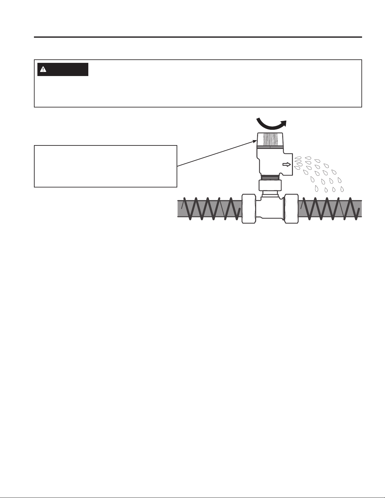
DANGER
Risk of Scald
Before manually operating the combined non-return/safety valve, make certain no one will be exposed to
the hot water released by the valve. The water may be hot enough to create a SCALD hazard. The water
should be released into a suitable drain to prevent injury or property damage.
Annual Maintenance
(DFKURWDWLRQRIWKHUHGFDSZLOODOORZDVKRUW
release of water. Rotate the red cap a full 5
rotations. Make sure valve operates freely. Allow
several gallons to flush through the discharge
line to an open drain.
49-6000121 Rev. 0
INSTALLATION INSTRUCTIONS
Installation Instructions
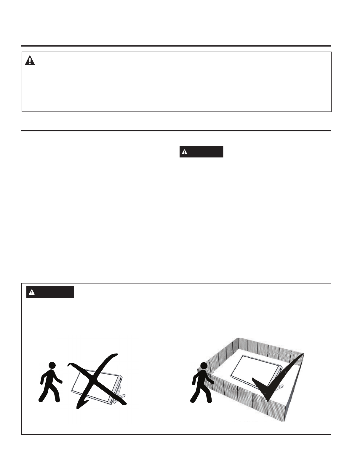
GENERAL INSTALLATION AND
TRANSPORT INSTRUCTIONS
Installation, maintenance, cleaning and all other
procedures listed in this manual shall only be
performed by fully and properly instructed, qualified
and authorized personnel, which means licensed
LQVWDOOHUVFRQWUDFWRUVSOXPEHUV+9$&DQGVRODU
contractors. The materials supplied must be used
for installation. Before any installation or operation
of the GeoSpring Solar system, familiarize yourself
with and then comply with all national, state and local
ODZVDQGUHJXODWLRQVWKDWDSSO\/LIWWKH*HR6SULQJ
Solar system only by its frame and NEVER by any
of the water connections or bolts. Incorrect lifting can
damage the GeoSpring Solar system. Always be
careful to avoid any physical damage, especially to
the solar glass, back wall and pipe connections. The
manufacturer is not liable for structural damage or
any other damage caused by improper handling or
incorrect installation.
ON ROOF INSTALLATION
Installation shall only be carried out on roof surfaces
or substructures with sufficient load bearing capacity.
The structural load bearing capacity of the roof or
substructure must be tested in terms of local and
regional conditions by a structural engineer before
installing the GeoSpring Solar system. During
inspection pay particular attention to the quality of the
substructure for retaining screw connections used to
secure the installation materials for the GeoSpring Solar
system. Inspection of the entire installation structure
in accordance with national and local regulations is
particularly necessary in areas with heavy snowfall
that can lead to increased load. When choosing the
installation location, make sure that maximum loads are
not exceeded by snowfall or wind forces.
The inspection should also take into account any
particularities of the installation location, e.g. air jets,
eddies etc. that can lead to increased load. There
must be a distance of at least 3 ft to the roof ridging or
edge. Structural members penetrated by solar system
components must meet code. Building materials
adjacent to solar components must not be exposed to
elevated temperatures.
Penetration through fire-rated assemblies must not
reduce fire resistance below code. Meet applicable
codes and national Roofing Contractors Association
practices. Do not impair enclosure function. Do not
allow vermin intrusion.
FLAT ROOF OR GROUND MOUNT
INSTALLATION
Installation shall only be carried out on roof surfaces
or substructures with sufficient load bearing capacity.
The structural load bearing capacity of the roof or
substructure must be inspected, tested and approved
in accordance with local and regional conditions by a
structural engineer before the GeoSpring Solar system
can be installed. During inspection, the structural
engineer must pay particular attention to the quality of
the substructure for proper anchoring of the retaining
screw connections used to secure the installation
materials for the GeoSpring Solar system. Inspection
of the entire installation structure in accordance with
national and local regulations is particularly necessary
in areas with heavy snowfall that can lead to increased
load. When choosing the installation location, make
sure that maximum loads are not exceeded by
snowfall or wind forces. There must be at a distance of
at least 3 ft to the roof ridging or edge.
NOTE: Installing a GeoSpring Solar system means
FKDQJLQJWKHVWUXFWXUHRIDQH[LVWLQJURRI([WHQGHG
and inhabited lofts or inadequate minimum roof
inclinations often require additional measures carried
out on-site by a licensed roofing contractor e.g.
sarking, to secure against water penetrating as a
result of wind pressure and drifting snow.
49-6000121 Rev. 0
Installation Instructions
CONNECTIONS AND PIPING
The GeoSpring Solar system shall be connected to
WKHFRQQHFWLRQSLSLQJZLWKDƎ137WKUHDG%HIRUH
tightening the connection, check to make sure that
VHDOVDUHSRVLWLRQHGSURSHUO\8VHDWRUTXHZUHQFKWR
tighten the connection and do not exceed a torque
of 30 ft-lbs. Please refer to Thermal Expansion and
/RFDO,QVWDOODWLRQ5HJXODWLRQVHFWLRQVIRUDGGLWLRQDO
information. Only use pipes suited for use in sanitary
facilities and which can withstand temperatures of at
OHDVW)7KH*HR6SULQJ6RODUV\VWHPUHTXLUHV
the use of all copper or brass fittings in the collector
loop plumbing. Couplings rather than unions should
be used to join the collectors to avoid leaks and fluid
ORVV8VHRQO\OHDGIUHHVROGHUNOTE: The piping
supports must not compress the insulation. If this is
not possible, insulate the piping supports as well. To
prevent dielectric corrosion, make sure that there
is no connection between stainless or galvanized
steel pipes and copper pipes.
COLLECTOR LOOP PIPE
INSULATION
The collector loop cold water supply and hot return
lines shall be well insulated with high quality flexible
FORVHGFHOOLQVXODWLRQWRPLQLPL]HKHDWORVV8VH
closed-cell tube insulation with a wall thickness of
ƎLQPLOGFOLPDWHV,QFROGFOLPDWHVZKHUHIUHH]LQJ
RFFXUVXVHLQVXODWLRQZLWKƎZDOOWKLFNQHVV
Any above ground exterior pipe insulation is subject
WR89GHJUDGDWLRQDQGPXVWEHMDFNHWHGZUDSSHG
with aluminum foil tape, or painted with two coats
of high quality water-based acrylic resin coating
as supplied by the insulation manufacturer. To the
extent possible, slide the insulation material over the
pipe without cutting or taping. Seal all butt joints with
contact adhesive. Do not use rigid polyethylene pipe
insulation. Insulate the pipes with a suitable material
of appropriate thickness in order to reduce heat loss
and protect the pipes from freezing. Do not insulate
the valves.
INCLINATION OF THE GEOSPRING
SOLAR SYSTEM
8VHWKH*HR6SULQJ6RODUV\VWHPRQO\LILWFDQEH
LQVWDOOHGVRWKDWLWKDVDQLQFOLQDWLRQRIDWOHDVW
EXWQRPRUHWKDQ3URWHFWWKHV\VWHPFRQQHFWLRQV
from contaminants entering the system, like dust etc.
INSTALLATION INSTRUCTIONS
49-6000121 Rev. 0
INSTALLATION INSTRUCTIONS
Installation Instructions
INSULATION
The manufacturer’s warranty does not cover any
damage or defect caused by installation, attachment
or use of any type of energy-saving or other
XQDSSURYHGGHYLFHVRWKHUWKDQWKRVHDXWKRUL]HGE\
the manufacturer) into, onto or in conjunction with the
water heater. The use of unauthorized energy-saving
devices may shorten the life of the water heater and
may endanger life and property.
The manufacturer disclaims any responsibility for
such loss or injury resulting from the use of such
unauthorized devices.
Application of any external insulation, blankets
or water pipe insulation to this water heater will
require careful attention to the following:
Ɣ'RQRWFRYHUWKHFRPELQHGQRQUHWXUQVDIHW\YDOYH
or ventilation valve.
Ɣ'RQRWFRYHUWKHRSHUDWLQJRUZDUQLQJODEHOV
attached to the water heater or attempt to relocate
them on the exterior of the insulation blanket.
WATER SUPPLY CONNECTIONS
Refer to the illustration below for suggested typical
installation. The hot and cold water connections are
FOHDUO\PDUNHGDQGDUH´137RQDOOPRGHOV
NOTE: Install a shut-off valve in the cold water line
near the water heater. This will enable easier service
or maintenance of the unit later.
NOTICE: Do not apply heat to the HOT or COLD
water connections. If sweat connections are
used, sweat tubing to adapter before fitting
the adapter to the cold water connections on
heater. Any heat applied to the hot or cold
water connection will permanently damage the
internal plastic lining in these ports.
THERMAL EXPANSION
Determine if a check valve exists in the inlet water
line. It may have been installed in the cold water line
as a separate backflow preventer, or it may be part
of a pressure-reducing valve, water meter or water
softener. A check valve located in the cold water inlet
OLQHFDQFDXVHZKDWLVUHIHUUHGWRDVD³FORVHGZDWHU
V\VWHP´$FROGZDWHULQOHWOLQHZLWKQRFKHFNYDOYHRU
EDFNIORZSUHYHQWLRQGHYLFHLVUHIHUUHGWRDVDQ³RSHQ´
water system.
As water is heated, it expands in volume and creates
an increase in the pressure within the water system.
7KLVDFWLRQLVUHIHUUHGWRDV³WKHUPDOH[SDQVLRQ´,QDQ
³RSHQ´ZDWHUV\VWHPH[SDQGLQJZDWHUZKLFKH[FHHGV
the capacity of the water heater flows back into the
city main where the pressure is easily dissipated.
$³FORVHGZDWHUV\VWHP´KRZHYHUSUHYHQWVWKH
expanding water from flowing back in to the main
VXSSO\OLQHDQGWKHUHVXOWRI³WKHUPDOH[SDQVLRQ´FDQ
create a rapid and dangerous pressure increase in the
water heater and system piping. This rapid pressure
increase can quickly reach the safety setting of the
relief valve, causing it to operate during each heating
cycle. Thermal expansion, and the resulting rapid and
repeated expansion and contraction of components
in the water heater and piping system, can cause
premature failure of the relief valve, and possibly the
heater itself. Replacing the relief valve will not correct
the problem!
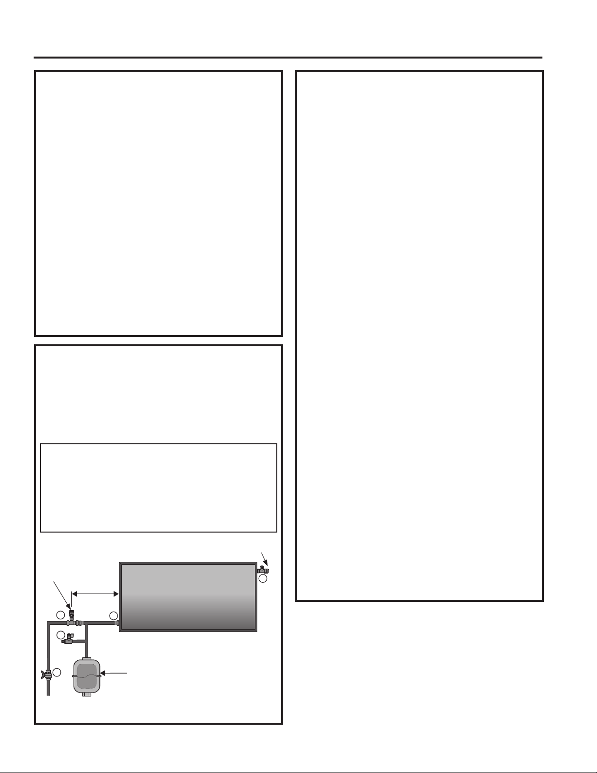
The suggested method of controlling thermal
expansion is to install an expansion tank in the cold
water line between the water heater and the check
valve. During installation, ensure the expansion
tank is properly supported to relieve weight loads off
connection pipes. The expansion tank is designed
with an air cushion built in that compresses as the
system pressure increases, thereby relieving the
over-pressure condition and eliminating the repeated
operation of the relief valve. Other methods of
controlling thermal expansion are also available.
Contact your installing contractor, water supplier, or
plumbing inspector for additional information regarding
this subject.
40 inch
Expansion Tank:
10 gallons, GepSpring Solar 50
7 gallons, GeoSpring Solar 40
5 gallons, GeoSpring Solar 25
1
2
3
4
6
3/4" NPT Hot
Water Outlet
3/4" NPT Cold
Water Inlet
JDOORQVRUJUHDWHU*HR6SULQJ6RODU
JDOORQVRUJUHDWHU*HR6SULQJ6RODU
5 gallons or greater, GeoSpring Solar 25
49-6000121 Rev. 0
LOCAL INSTALLATION
REGULATIONS
This water heater must be installed in accordance
with these instructions, local codes, utility codes,
utility company requirements or, in the absence of
local codes, the latest edition of the National Electrical
Code. It is available from some local libraries or
can be purchased from the National Fire Prevention
$VVRFLDWLRQ%DWWHU\PDUFK3DUN4XLQF\0$DV
ERRNOHW$16,1)3$
The solar energy system shall comply with building
code, plumbing code, mechanical code, and fire code
adopted by the authority having jurisdiction or, in the
absence of such codes, with the International Building
Code, International Plumbing Code, International
Mechanical Code, and International Fire Code.
Installation Instructions
RELIEF VALVE
CAUTION
RISK OF UNIT DAMAGE - THE
PRESSURE RATING OF THE RELIEF VALVE
MUST NOT EXCEED 60 PSI (413.6 KPA), THE
MAXIMUM WORKING PRESSURE OF THE
WATER HEATER AS MARKED ON THE RATING
PLATE.
$OLVWHGDQGODEHOHGSUHVVXUHUHOLHIYDOYHFRPELQHG
non-return/safety valve) is supplied and must remain
installed in the opening provided and marked for the
purpose on the water heater. No valve of any type
should be installed between the relief valve and the
WDQN/RFDOFRGHVVKDOOJRYHUQWKHLQVWDOODWLRQRI
relief valves.
7KH%78+UDWLQJRIWKHUHOLHIYDOYHPXVWQRWEH
less than the input rating of the water heater as
LQGLFDWHGRQWKHUDWLQJODEHOORFDWHGRQWKHKHDWHU
ZDWW %78+
Connect the outlet of the relief valve to a suitable
open drain so that the discharge water cannot
contact live electrical parts or persons and to
eliminate potential water damage.
Piping used should be of a type approved for hot
water distribution. The discharge line must be no
smaller than the outlet of the valve and must pitch
downward from the valve to allow complete drainage
E\JUDYLW\RIWKHUHOLHIYDOYHDQGGLVFKDUJH
line. The end of the discharge line should not be
threaded or concealed and should be protected from
freezing. No valve of any type, restriction or reducer
coupling should be installed in the discharge line.
RELIEF VALVE (Cont.)
CAUTION
RISK OF SCALD AND
PROPERTY DAMAGE
To reduce the risk of excessive pressures in this
water heater, install pressure protective equipment
required by local codes and no less than a pressure
relief valve certified by a nationally recognized
testing laboratory that maintains periodic inspection
of production of listed equipment or materials.This
valve must be marked with a maximum set pressure
not to exceed the marked maximum working
pressure of the water heater. Install the valve into
an opening provided and marked for this purpose
in the water heater, and orient it or provide tubing
so that any discharge from the valve exits only
ZLWKLQLQFKHVDERYHRUDWDQ\GLVWDQFHEHORZ
the structural floor, and does not contact any live
electrical part. The discharge opening must not be
blocked or reduced in size under any circumstances.
INSTALLATION INSTRUCTIONS
49-6000121 Rev. 0
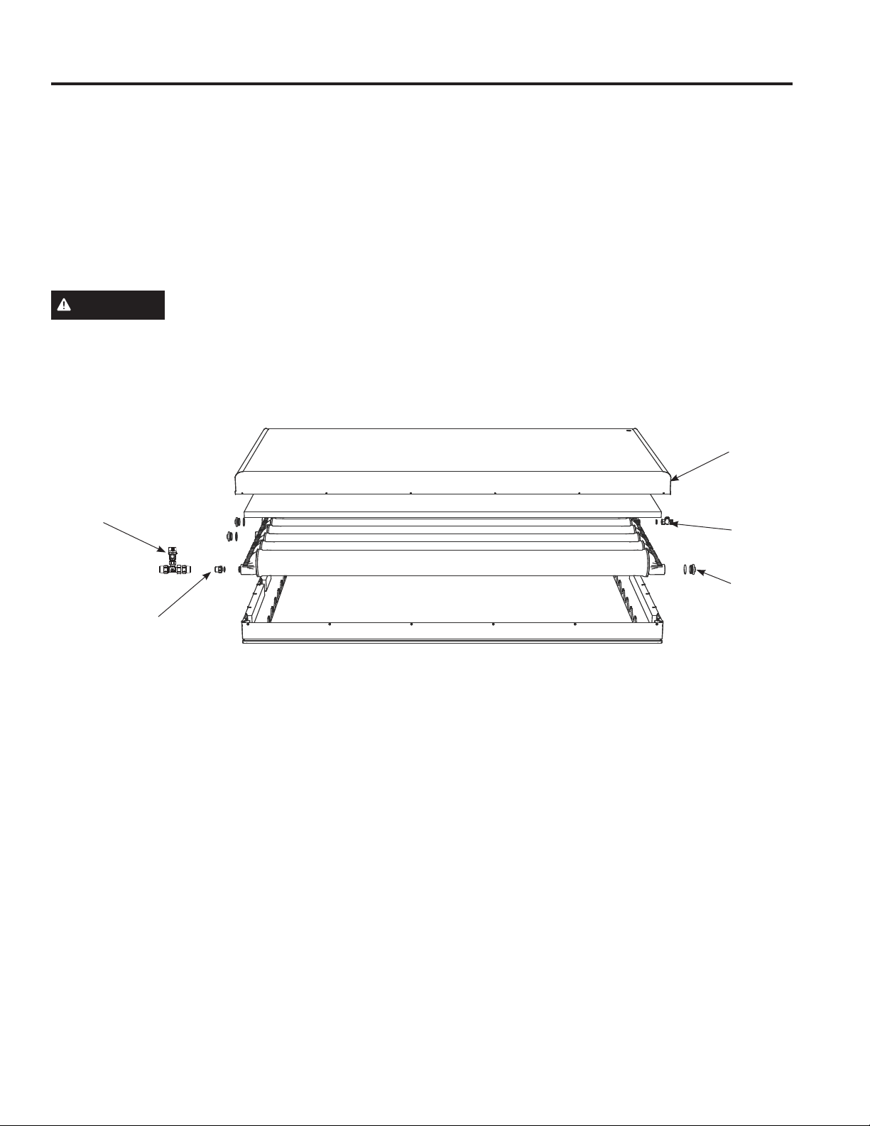
INSTALLATION INSTRUCTIONS
Installation Instructions
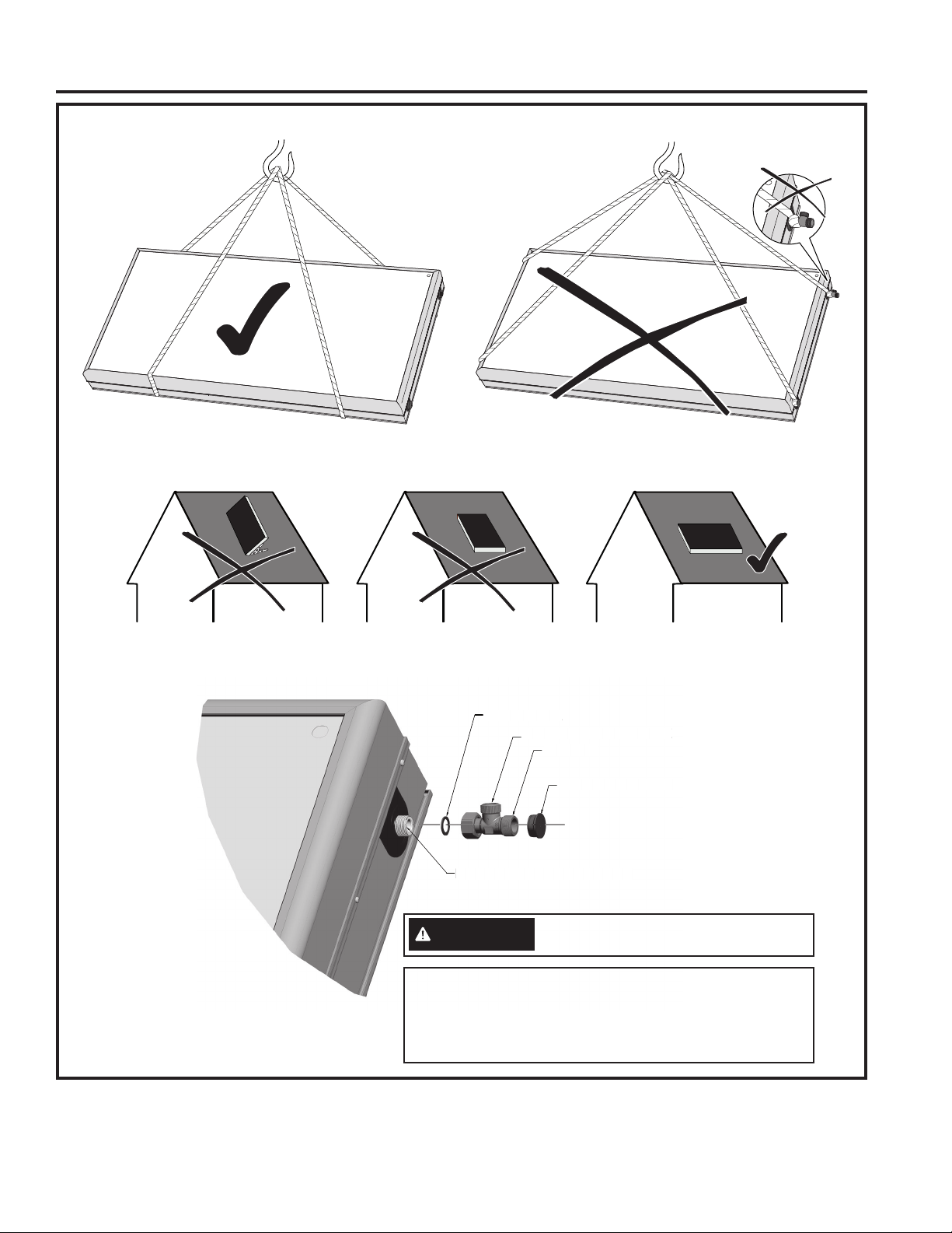
TRANSPORTING PANELS
3/4 NPT
FLAT SEAL
VENTILATION VALVE
THREAD PROTECTOR
MAX.TORQUE 30 FT-LBS
3/
4 NP
T
FL
AT
S
EA
L
VENTILATI
O
N VALV
E
THREAD PR
O
TE
C
M
AX.T
O
R
Q
UE 30 FT-LB
S
CAUTION
Mount ventilation valve vertically upward
when installed.
NOTICE: 5LVNRI8QLW'DPDJH
The MAXIMUM torque on the ventilation valve nut and plastic
threaded connection point shall NOT H[FHHG)7/%67KH
water heater warranty does not cover damage or failure resulting
from over-torque connection points.
49-6000121 Rev. 0
Installation Instructions
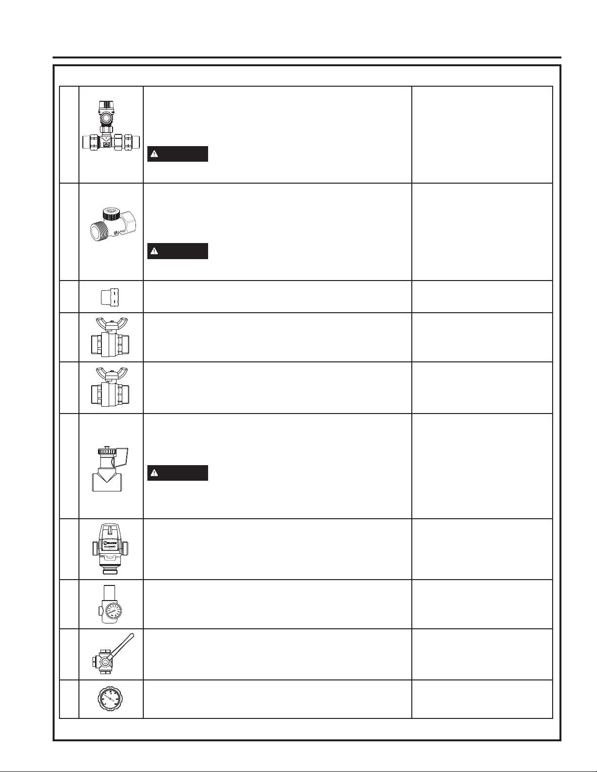
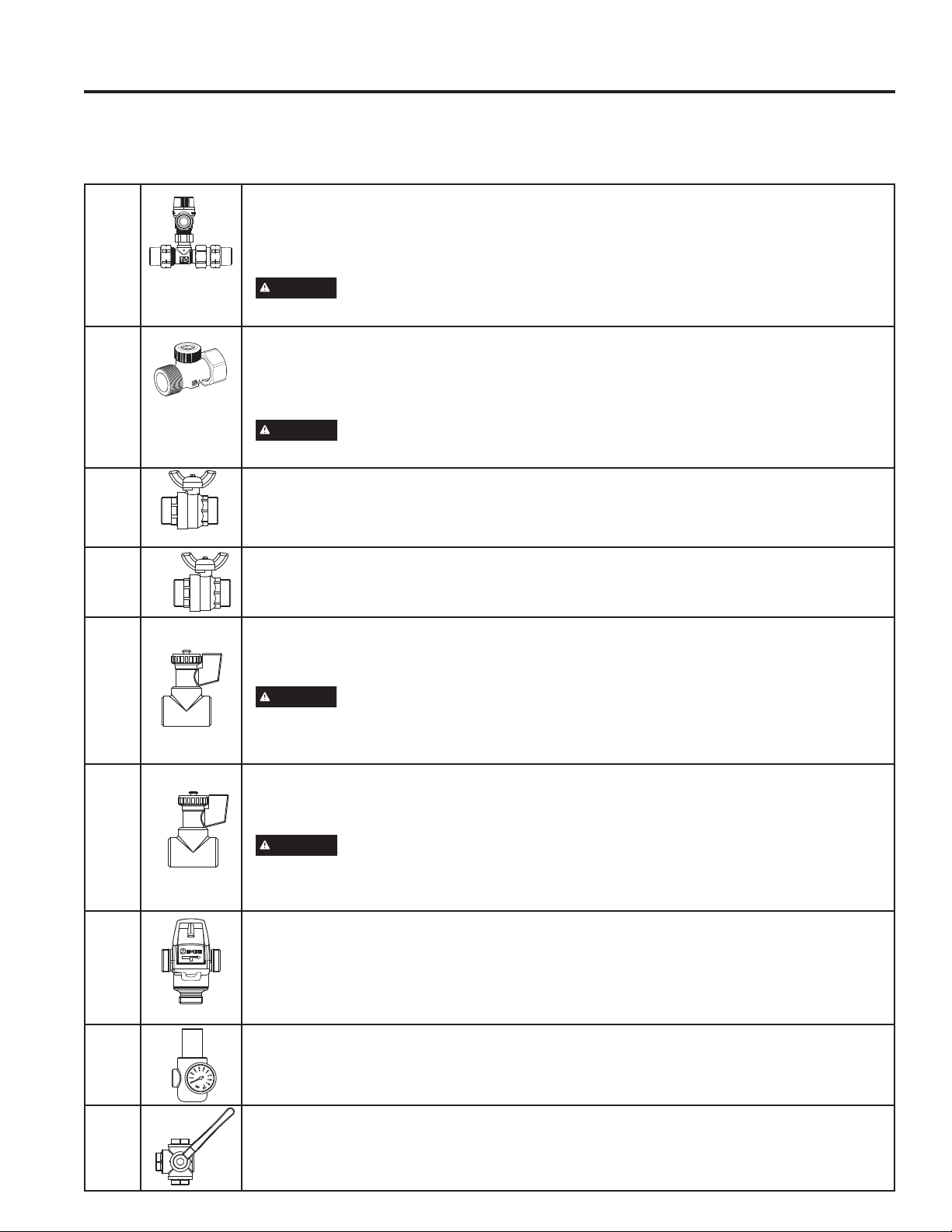
COMPONENTS
1
COMBINED NON-RETURN/SAFETY VALVE
This valve is a pressure release mechanism used in pressure systems.
It has a non-return valve integrated. The use of these valves is strictly
required due to safety regulations. The safety valve opens at a pressure of
36,WRUHGXFHH[FHVVSUHVVXUH
Valve must be replaced by year five to gain the limited warranty for
years six through ten.
WARNING
BURN HAZARD
Do NOT touch hot water outlet pipes. Failure to do so can result in
severe burns.
Ǝ13736,2SHQ3UHVVXUH
0D[ZRUNLQJWHPSHUDWXUH)
5HOLHI7KUHDG*
2
VENTILATION VALVE
This valve ensures that no vacuum is created when draining the water tank.
In the event of negative pressure, the ventilation valve automatically
supplies the system with air. This ventilation valve must comply with ANSI
=
Valve must be replaced by year five to gain the limited warranty for
years six through ten.
WARNING
BURN HAZARD
Do NOT touch hot water outlet pipes. Failure to do so can result in
severe burns.
)HPDOH*Ǝ[Ǝ0137ZLWK'1
VRODUQHRSHUOEDFNIORZSUHYHQWHU89
resistant
Material: brass
0D[ZRUNLQJWHPSHUDWXUH)
3
NPT THREAD ADAPTOR
This nipple is a thread converter for use with metric threads to convert to
English NPT threads.
3/4" MNPT x Female G3/4"
4
COLD WATER SUPPLY ISOLATION VALVE
This valve should stay open to allow water from the public water system
to fill the GeoSpring water tank. When this valve is closed, the GeoSpring
Solar system and the supplemental water heater are disconnected from the
pressurized mains of the public water system.
Ǝ137IXOO\SRUWHG%UDVV%DOO9DOYH
for plumbing, Max. safe operating
SUHVVXUH36,WHPSHUDWXUHUDQJH
XSWR)
Material to be provided by contractor.
5
HOT WATER SUPPLY ISOLATION VALVE
Keep this valve open to assure that hot water can drain or escape in case
of overheating. This valve can temporarily be closed for maintenance
purposes.
Ǝ137IXOO\SRUWHG%UDVV%DOO
9DOYHIRUSOXPELQJDSSOLFDWLRQV0D[
VDIHRSHUDWLQJSUHVVXUH36,
WHPSHUDWXUHUDQJHXSWR)
Material to be provided by contractor.
6
DRAIN VALVE
7KHVHZDWHUKHDWHUGUDLQVDUHQRUPDOO\FORVHGDQGFDSSHG8VHWKHVH
valves to drain the GeoSpring Solar system. Attach a garden hose to
both drain valves. Terminate the hoses in either a service basin or an
appropriate spot outside the house. Open both water heater drains at once
to drain the unit.
WARNING
SCALD RISK
WATER MAY BE DISCHARGED AT VERY HIGH
TEMPERATURES. TO AVOID SCALDING, EXERCISE MAXIMUM
CAUTION WHEN DRAINING THE HOT WATER FROM THE GEOSPRING
SOLAR SYSTEM. DO NOT POINT HOSE AT PERSONS OR PETS.
ALWAYS DISCHARGE THE HOT WATER TO A SAFE PLACE.
ƎXQLERG\EDOOYDOYH
0D[WHPSHUDWXUH)
Material: Brass
Material to be provided by contractor.
7
THERMOSTATIC MIXING VALVE
This valve controls the temperature of the warm water output. According
to local standards the valve must have a scald safe function. Scald safe
means that in the case of a cold water failure, the hot water supply shuts off
automatically.
$Q$66(UDWHGPL[LQJYDOYH
to avoid severe burns or death from
VFDOGLQJWHPSHUDWXUHV,65(48,5('
3(565&&2*
Material to be provided by contractor.
8
PRESSURE REDUCING VALVE
7KLVYDOYHVKRXOGHQVXUHDFRQVWDQWRXWSXWSUHVVXUHRI36,LQGHSHQGHQW
of the input pressure delivered from any source.
3UHVVXUHVHWSRLQWUDQJHWR36,
Material: Brass
Material to be provided by contractor.
9
3 WAY BALL VALVE
This valve provides solar system cold water shut off without interrupting
normal cold water service.
0D[SUHVVXUH36,
Material: Brass
7HPSHUDWXUH5DQJHXSWR)
Material to be provided by contractor.
10
THERMOMETER
To determine whether the solar system is working, it is necessary to install
a thermometer.
7HPSHUDWXUH5DQJH)WR)
Material to be provided by contractor.
NOTE: Always follow component manufacturers recommendations with parts not supplied with the GeoSpring Solar system.
INSTALLATION INSTRUCTIONS
49-6000121 Rev. 0
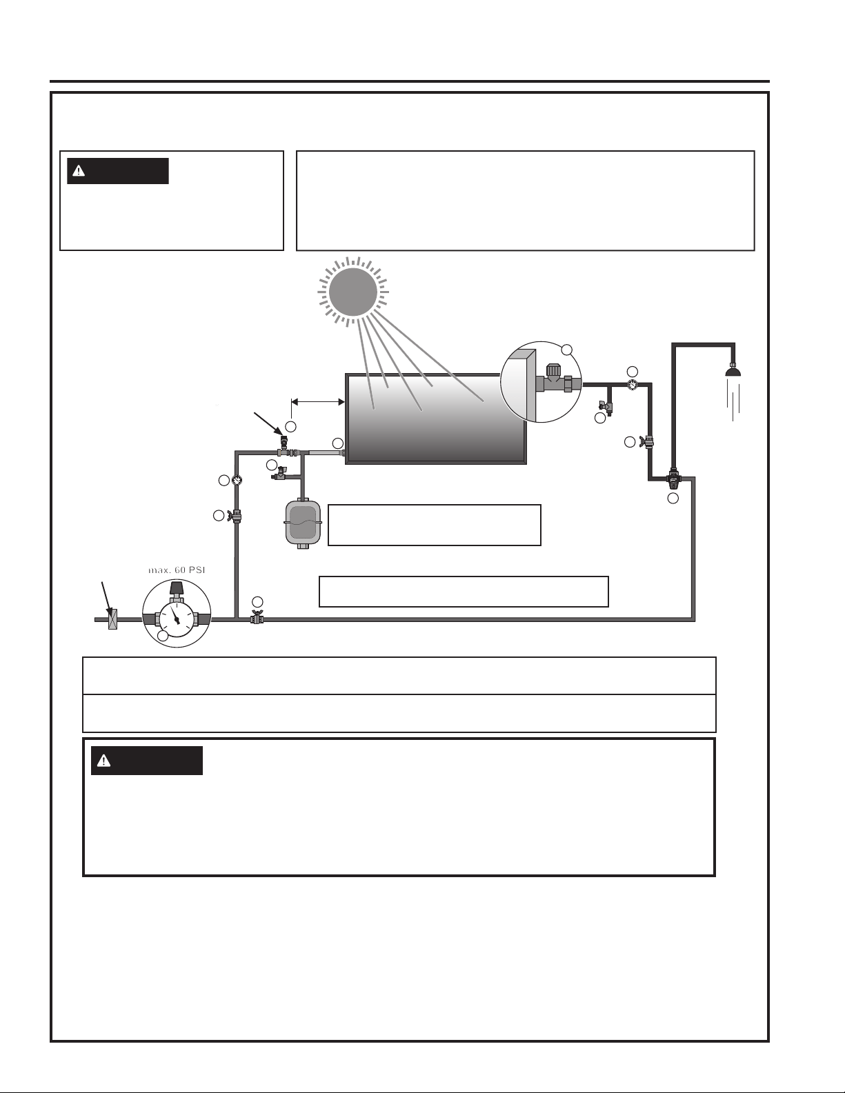
INSTALLATION INSTRUCTIONS
HYDRAULIC CONNECTION
Stand Alone 7KLVV\VWHPLV12765&&FHUWLILHG
Installation Instructions
3OHDVHQRWHWKDWDWKUHDGDGDSWHUKDVWREHXVHGIRU$PHULFDQ137WKUHDGVLQFRPELQDWLRQZLWK
GeoSpring Solar system connections and valves.
To protect the system for inconsistent pressure or pressure damage we recommend using an
expansion tank.
WARNING
RISK OF PERSONAL INJURY
TO AVOID SERIOUS BODILY INJURY OR DAMAGE, ALL COMPONENTS SHOWN IN THE
DRAWING ABOVE MUST BE INSTALLED.
THE MAXIMUM OPERATING PRESSURE IN THE WATER CIRCUIT MUST BE LIMITED TO 60
PSI AT ALL TIMES.
INSTALL A PRESSURE REDUCER IF NECESSARY.
6HHSDJHIRUGHWDLOVRQWKHFRPSRQHQWV
NOTES:
Whole Home Water Filter:
Ɣ (QVXUHZDWHUTXDOLW\FRPSOLHVZLWK6SHFLILFDWLRQVRI:DWHU4XDOLW\VHFWLRQ3DJH
Combined Non-Return/Safety Valve:
Ɣ Contains integrated check valve. Ensure proper orientation.
Ɣ 9DOYHRSHQVDWDSUHVVXUHRI36,WRUHGXFHH[FHVVSUHVVXUH&RQQHFWWKHRXWOHWRIWKHUHOLHIYDOYH
to a suitable open drain.
40 inch
7
4
4
6
1
3
PSI
0
30
60
15 45
8
max. 60 PSI
2
6
5
10
10
&ROOHFWRUORRSSLSLQJPDWHULDOFRSSHURSHUDWLQJ
WHPSHUDWXUH)RUKLJKHUGLDPHWHUQRWOHVVWKDQ´
Whole Home
Water Filter
*DOORQVRUJUHDWHU*HR6SULQJ6RODU
*DOORQVRUJUHDWHU*HR6SULQJ6RODU
5 Gallons or greater, GeoSpring Solar 25
DANGER
Scald Risk
Mixing valve must be set to auxiliary
water heater temperature or below.
Failure to do so may result in severe
burns or death from scalds.
NOTICE: Your warranty is void if you operate the GeoSpring
TM
Solar without a
SUHVVXUHUHGXFLQJYDOYHVHWDW36,RUORZHU
The combined non-return/safety valve can be placed at distances greater than
LQFKHVIURPWKHSURGXFW7RGRVR\RXMUST ensure the pressure measured
DWWKHSURGXFWGRHVQRWH[FHHG36,GXULQJRSHUDWLRQ
See Notes
49-6000121 Rev. 0
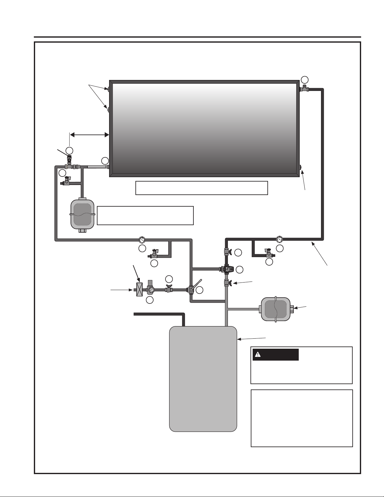
HYDRAULIC CONNECTION
Pre-heater Electric & Gas Storage Water Heater
8
9
4
5
6
10 10
1
6
7
2
3
40 inch
6
HOT COLD
Installation Instructions
Auxiliary Water Heating Equipment
Auxiliary water heater must have adequate capacity, listed and labeled by an accredited listing organization.
6HHSDJHIRUGHWDLOVRQWKHFRPSRQHQWV
NOTES:
Whole Home Water Filter:
Ɣ Ensure water quality complies with
Specifications of Water Quality section
3DJH
Combined Non-Return/Safety Valve:
Ɣ Contains integrated check valve. Ensure
proper orientation.
Ɣ 9DOYHRSHQVDWDSUHVVXUHRI36,WR
reduce excess pressure. Connect the
outlet of the relief valve to a suitable open
drain.
DANGER
SCALD RISK
Mixing valve must be set to the auxiliary
water heater temperature or below.
Failure to do so may result in severe
burns or death from scalds.
NOTICE: Your warranty is void if you
operate the GeoSpring
TM
Solar without a
SUHVVXUHUHGXFLQJYDOYHVHWDW36,RU
lower.
The combined non-return/safety valve
can be placed at distances greater than
LQFKHVIURPWKHSURGXFW7RGRVR\RX
MUST ensure the pressure measured at
WKHSURGXFWGRHVQRWH[FHHG36,GXULQJ
operation.
&ROOHFWRUORRSSLSLQJPDWHULDOFRSSHURSHUDWLQJ
WHPSHUDWXUH)RUKLJKHUGLDPHWHUQRWOHVVWKDQ´
Optional-
Sensor Immersion
Sleeve
Optional-
Sensor Immersion
Sleeve
Hot Water Outlet
Auxilary Storage
Water Heater
Isolation valve or check valve
3UHYHQWVEDFNIORZZKHQV\VWHP
is inactive)
Existing Water Heater
Expansion Tank
Cold Water Inlet
INSTALLATION INSTRUCTIONS
See Notes
*DOORQVRUJUHDWHU*HR6SULQJ6RODU
*DOORQVRUJUHDWHU*HR6SULQJ6RODU
5 Gallons or greater, GeoSpring Solar 25
Whole Home
Water Filter
49-6000121 Rev. 0
INSTALLATION INSTRUCTIONS
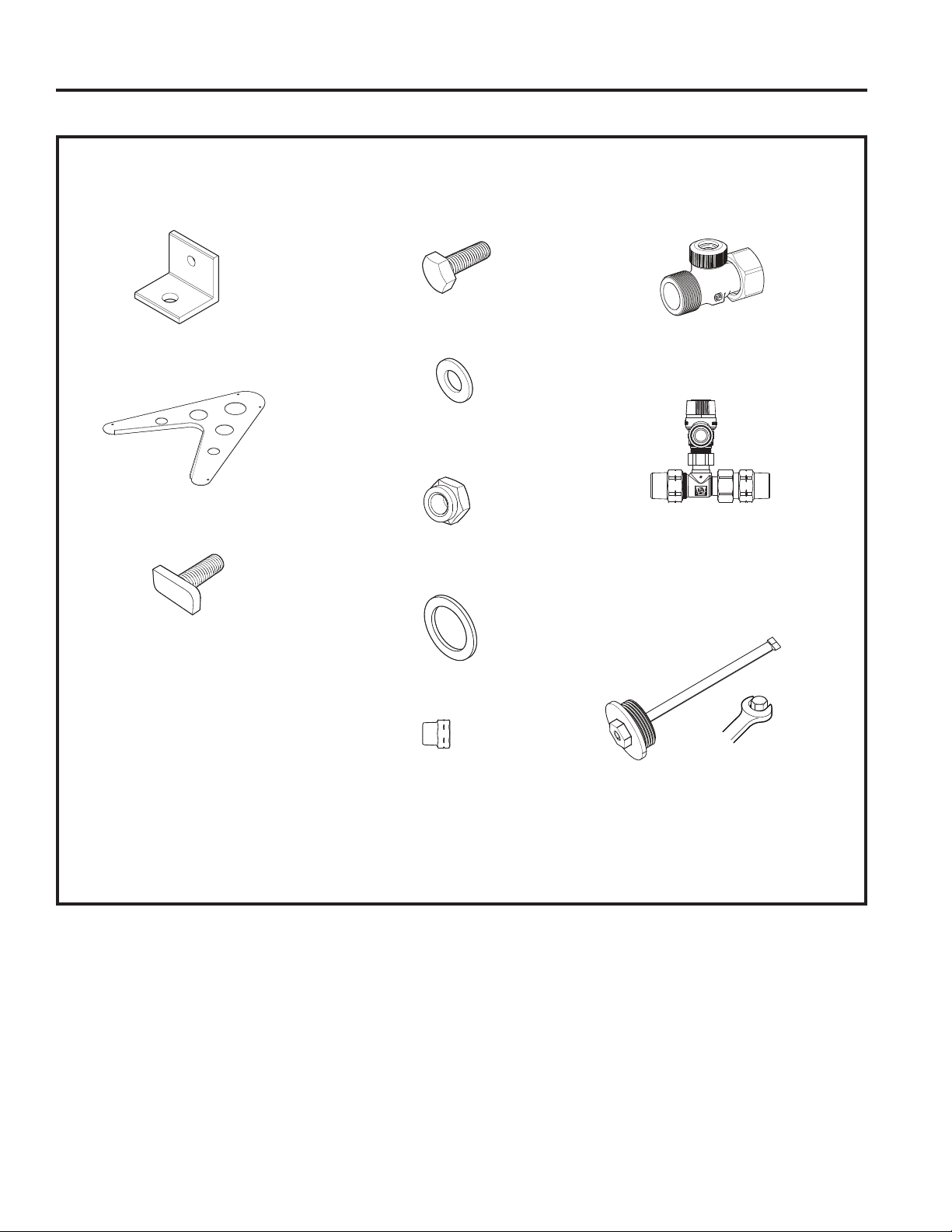
Installation Instructions
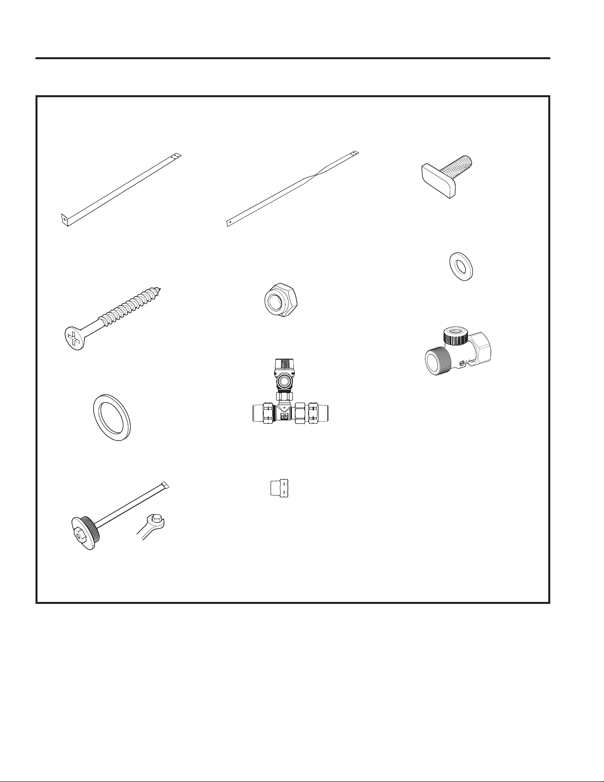
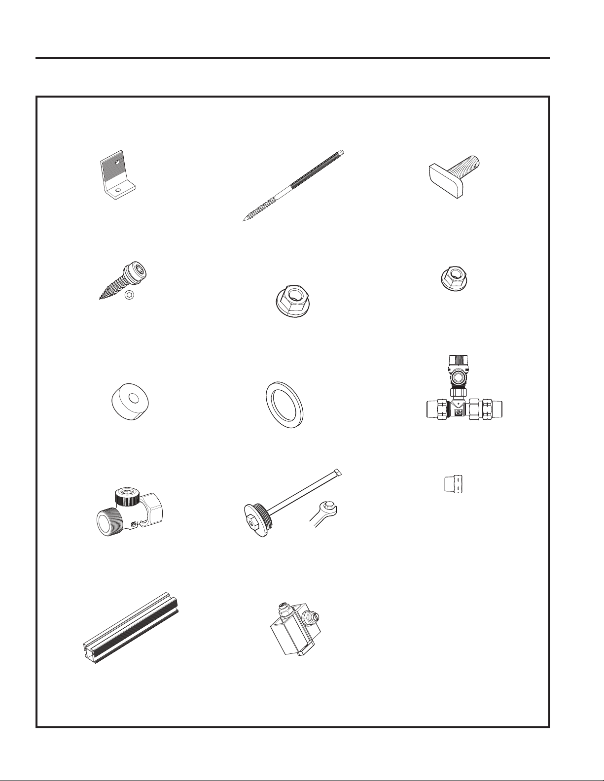
Materials for Flat Roof or Ground Mount Installation
NOTE: Check package contents to make sure that you have received all components listed below. If you need
spare parts, please contact your local GeoSpring Solar system dealer.
Mounting Bracket - Qty. 4
&ROOHFWRU/HJ4W\
0HWULF7+HDG%ROW0[
Qty. 4
0HWULF%ROW0[4W\
)ODW:DVKHU04W\
0HWULF1XW04W\
)ODW6HDO4W\
3/4" MNPT x Female G3/4"
7KUHDG$GDSWRU)DFWRU\
,QVWDOOHG4W\
3/4" MNPT x Female G3/4"
9HQWLODWLRQ9DOYH4W\
3/4" NPT Combined Non-
5HWXUQ6DIHW\9DOYH4W\
Sensor Emersion Sleeve
2SWLRQDO±8VHGWRPHDVXUH
temperatures inside the tank)
FLAT ROOF OR GROUND MOUNT INSTALLATION
21
22 49-6000121 Rev. 0
Installation Instructions
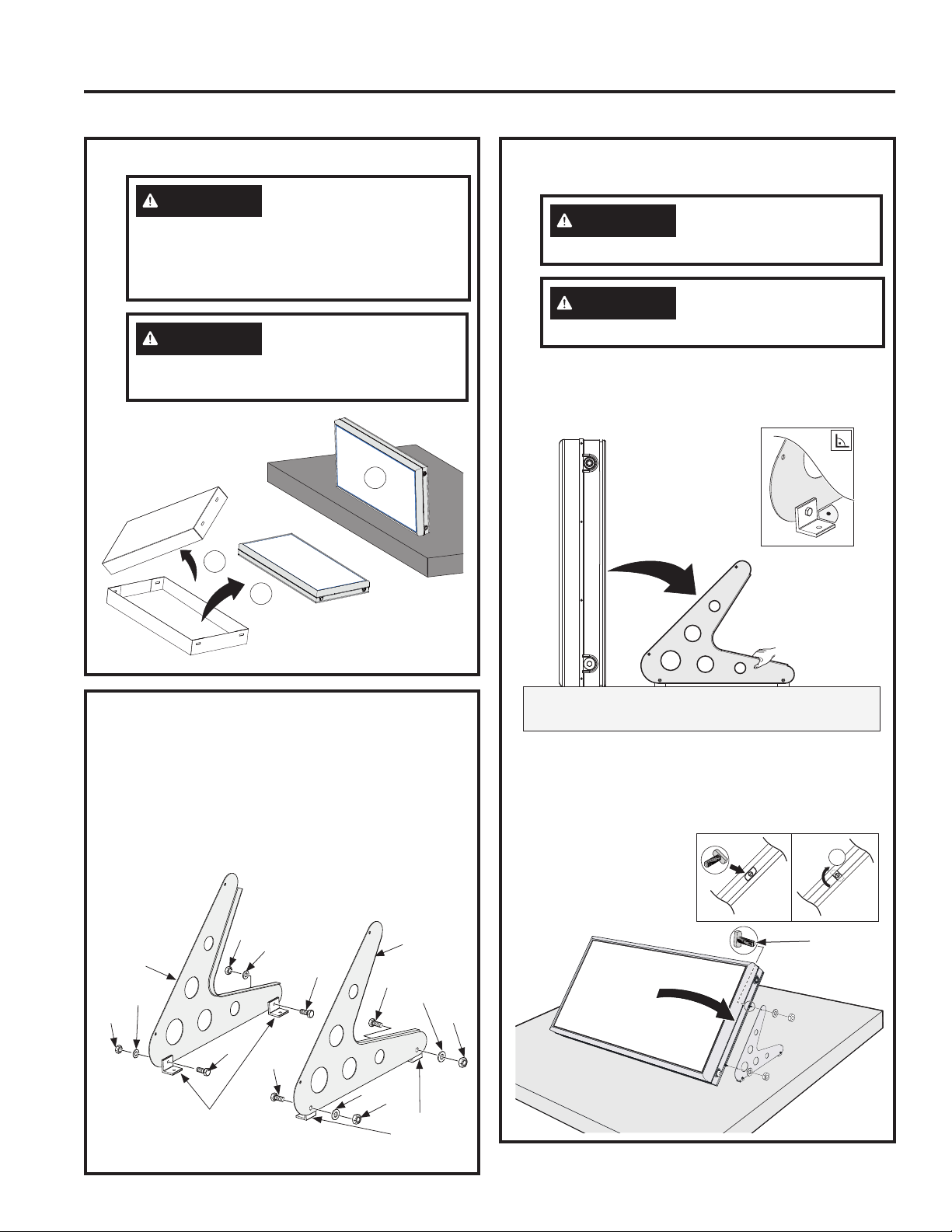
1. Unpack the Unit
2. Assemble Collector Legs
Ŷ$WWDFKWKHIRXUPRXQWLQJEUDFNHWVWRWKHULJKW
and left collector legs using the bolts, nuts, and
washers provided.
COLLECTOR LEGS MAY HAVE SHARP
EDGES. HANDLE WITH CARE TO AVOID
BODILY HARM AND/OR PROPERTY
DAMAGE.
WARNING
TO AVOID BODILY HARM
AND/OR PROPERTY DAMAGE, HAVE TWO
PEOPLE JOINTLY INSTALL THE PRODUCT.
FRAGILE PRODUCT – HANDLE WITH
CARE!
CAUTION
THE FOLLOWING STEPS
MUST BE PERFORMED BY A LICENSED
CONTRACTOR.
1a
1b
1c
FLAT ROOF OR GROUND MOUNT INSTALLATION
Collector
/HJ
Bolt
Nut
Nut
Nut
Nut
Bolt
Washer
Washer
Washer
Washer
Bolt
Bolt
Collector
/HJ
Mounting
Brackets
Mounting
Brackets
3. Install Collector Panel to
Collector Legs
Ŷ2QHSHUVRQVKRXOGWLOWWKHSDQHOVORZO\ZKLOHWKH
second person attaches the panel to collector
legs using the special metric T-head bolts.
Ŷ
8VLQJDIODWKHDGVFUHZGULYHUWXUQWKH7KHDGEROW
WRORFNWKHEROWLQWRWKHJURRYHRQWKHSDQHO
7LJKWHQWKHQXWVZLWKDWRUTXHRIIWOEV
WARNING
Two people are required
for this procedure.
CAUTION
Ensure that the collector
leg is stabilized and secured.
90°
T-head
Bolt
INSTALLATION INSTRUCTIONS
49-6000121 Rev. 0 23
INSTALLATION INSTRUCTIONS
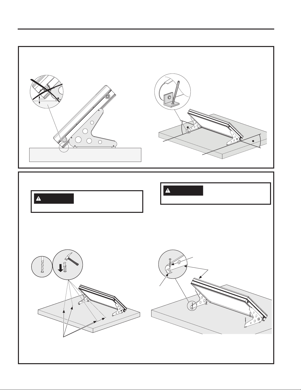
5. Install Collector Panel Assembly
Ŷ&DUHIXOO\PRYHWKHDVVHPEO\
Ŷ8VLQJDPPGULOOELWRUHTXLYDOHQWGULOOSLORW
holes into the structure at the marks made in
step 4.
Ŷ+DPPHUDSXUFKDVHGSODVWLFDQFKRULQWRWKH
holes made for the screws.
Ŷ&DUHIXOO\PRYHWKHDVVHPEO\EDFNLQWRSRVLWLRQ
Ŷ0RXQWWKHDVVHPEO\WRWKHVWUXFWXUHXVLQJ
anchor screws and make sure the brackets are
DWDDQJOHZLWKWKHFROOHFWRUOHJV6HFXUHO\
WLJKWHQWKHIRXUEROWVZLWKDWRUTXHRIIWOEV
Installation Instructions
FLAT ROOF OR GROUND MOUNT INSTALLATION
4. Prepare to Install Collector Panel Assembly
Ŷ0DNHVXUHWKDWWKHERWWRPHGJHRIWKHSURGXFW
touches the surface for support.
Ŷ0DNHVXUHWKHFROOHFWRUOHJVDUHSDUDOOHODQG
mark the attachment points.
CAUTION
Use caution when moving
assembly.
CAUTION
Use caution when moving
assembly.
Pilot Holes
1
2
Mounting
Bracket
Anchor
Screw
Collector
Assembly
Drill Pilot
Holes in
4 places
Hammer plastic
anchors into
pilot holes
24 49-6000121 Rev. 0
6. Final Installation Steps
Ŷ&RQQHFWWKHFROGZDWHULQOHWDQGILOOWKH
FROOHFWRU8VHWKHWKUHDGDGDSWRUVIRU86
137WKUHDGV5HIHUHQFH+\GUDXOLF&RQQHFWLRQ
and ventilation valve installation section)
Ŷ&RQQHFWWKHKRWZDWHURXWOHW
Ŷ5HPRYHWKHIRLOZLWKLQGD\VRILQVWDOOLQJWKH
GeoSpring Solar system but never before the
system is filled!
Installation Instructions
FLAT ROOF OR GROUND MOUNT INSTALLATION
NOTICE: Risk of Unit Damage
Do NOT insulate combined non-return/
safety valve or ventilation valve. The water
heater warranty does not cover damage
or failure resulting from operation with
insulated valves.
NOTICE:
Do not use more than 30 ft-lbs torque!
NOTICE:
Do not use more than 30 ft-lbs torque!
)ODW6HDO)DFWRU\,QVWDOOHG
Flat Seal
Hot Water
Outlet
9HQWLODWLRQ9DOYH
+RW:DWHU
Cold
Water
Inlet
INSTALLATION INSTRUCTIONS
49-6000121 Rev. 0 25
INSTALLATION INSTRUCTIONS
Installation Instructions
Materials for On-Roof Installation
NOTE: Check package contents to make sure that you have received all components listed below. If you need
spare parts, please contact your local GeoSpring Solar system dealer.
/RZHU 0RXQWLQJ %UDFNHW
Qty. 2
:RRG6FUHZ4W\
)ODW6HDO4W\
21
Sensor Immersion Sleeve
RSWLRQDO±8VHGWRPHDVXUH
temperatures inside the tank)
Flexible Mounting Bracket -
Qty. 2
0HWULF1XW04W\
´137&RPELQHG1RQ
5HWXUQ6DIHW\9DOYH4W\
´0137[)HPDOH*´
7KUHDG$GDSWRU)DFWRU\
,QVWDOOHG4W\
0HWULF7+HDG%ROW0[
Qty. 4
)ODW:DVKHU04W\
3/4" MNPT x Female G3/4"
9HQWLODWLRQ9DOYH4W\
ON-ROOF INSTALLATION
49-6000121 Rev. 0
Installation Instructions
Panel as Installed
ON-ROOF INSTALLATION
CAUTION
THE FOLLOWING STEPS MUST
BE PERFORMED BY A LICENSED ROOFING
CONTRACTOR.
/RZHU
Mounting
Bracket
with Wood
Screws
/RZHU
Mounting
Bracket
with
Wood
Screws
Metric T-Head Bolt
Flat Washer
Metric Nut
Metric T-Head Bolt
Flat Washer
Metric Nut
Metric T-Head Bolt
Flat Washer
Metric Nut
Metric T-Head Bolt
Flat Washer
Metric Nut
Solar Collector Panel
Roof Beams
Flexible
Mounting
Bracket with
Wood Screws
Flexible
Mounting
Bracket with
Wood Screws
LQFKHV LQFKHV
1. Install Lower Mounting Brackets to Roof Beams
Ŷ'HWHUPLQHWKHORFDWLRQRIWKH&ROOHFWRU3DQHO
Make sure the outermost beams are between 2
DQGLQFKHVIURPWKHVLGHVRIWKHSDQHO
Ŷ/LIWRUUHPRYHWKHURRILQJPDWHULDO8VHRIWKH
ZRRGVFUHZVSURYLGHGSHUEUDFNHWWRLQVWDOOWKH
lower Mounting Brackets to the roof beams.
Ŷ5HSODFHWKHURRILQJPDWHULDO
Wood
Screws
/RZHU
Mounting
Bracket
INSTALLATION INSTRUCTIONS
49-6000121 Rev. 0
INSTALLATION INSTRUCTIONS
ON-ROOF INSTALLATION
2. Place Collector Panel
Ŷ3ODFHD0HWULF7+HDG%ROWWKURXJKWKH
end of each of the brackets with the
head toward the panel. Attach a washer
and a nut to the end of each bolt. Do not
tighten. The T-Head should be turned so
it will fit into the groove of the panel.
Ŷ3ODFHWKHFROOHFWRUSDQHORQWRWKH
brackets on the roof sliding it down until
it fits up against the bracket. Turn the
7+HDG%ROWVRLWZLOOILWLQWRSDQHO
See figure.
Ŷ8VHDZUHQFKWRWLJKWHQHDFKQXW
IWOEV
3. Attach Flexible Bracket to the Roof
Ŷ/LIWRUUHPRYHURRILQJPDWHULDO8VHRI
WKHZRRGVFUHZVSURYLGHGSHUEUDFNHW
to install the Flexible Mounting Brackets
to the roof beams.
Ŷ5HSODFHWKHURRILQJPDWHULDO
Installation Instructions
WARNING
TO AVOID
BODILY HARM AND/OR PROPERTY
DAMAGE, HAVE TWO PEOPLE
JOINTLY INSTALL THE PRODUCT.
FRAGILE PRODUCT – HANDLE
WITH CARE!
Metric T-Head Bolt
Flat Washer
Metric Nut
Wood
Screws
Flexible
Mounting
Bracket
/RZHU0RXQWLQJ
Bracket
90°
49-6000121 Rev. 0
4. Attach Flexible Bracket to the Collector Panel
Ŷ3ODFHD0HWULF7+HDG%ROWWKURXJKWKHHQG
of each of the Flexible Brackets with the
head toward the panel. Attach a washer and
a nut to the end of each bolt. Do not tighten.
Ŷ3ODFHWKHEROWKHDGLQWRWKHJURRYHRQWKH
side of the panel. Do this on each side.
Ŷ8VLQJDVFUHZGULYHURQWKHHQGRIWKHEROW
WXUQWKHEROWWRORFNWKHEROWLQWRWKH
groove.
Ŷ7LJKWHQWKHQXWVWRPDNHWKHEUDFNHWVVHFXUH
IWOEV
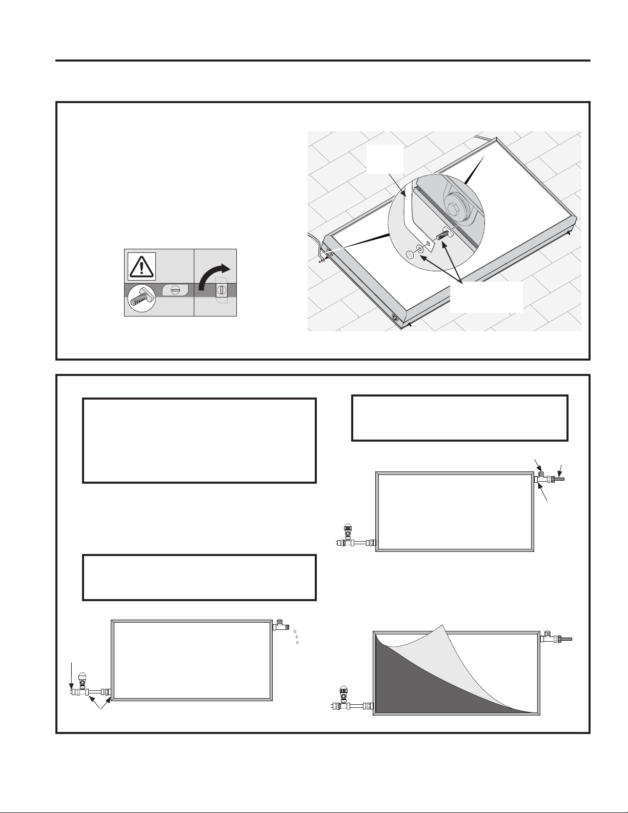
5. Final Installation Steps
Ŷ&RQQHFWWKHFROGZDWHULQOHWDQGILOOWKHFROOHFWRU
8VHWKHWKUHDGDGDSWRUVIRU86137WKUHDGV
5HIHUHQFH+\GUDXOLF&RQQHFWLRQDQGYHQWLODWLRQ
valve installation section)
Ŷ&RQQHFWWKHKRWZDWHURXWOHW
Ŷ5HPRYHWKHIRLOZLWKLQGD\VRILQVWDOOLQJWKH
GeoSpring Solar system but never before the
system is filled!
NOTICE: Risk of Unit Damage
Do NOT insulate combined non-return/safety
valve or ventilation valve. The water heater
warranty does not cover damage or failure
resulting from operation with insulated
valves.
NOTICE:
Do not use more than 30 ft-lbs torque!
NOTICE:
Do not use more than 30 ft-lbs torque!
Installation Instructions
ON-ROOF INSTALLATION
Metric T-Head Bolt
Flat Washer
Metric Nut
Flexible
Mounting
Bracket
90°
)ODW6HDO)DFWRU\,QVWDOOHG
Flat Seal
Hot Water
Outlet
9HQWLODWLRQ9DOYH
+RW:DWHU
Cold Water
Inlet
INSTALLATION INSTRUCTIONS
49-6000121 Rev. 0
INSTALLATION INSTRUCTIONS
Installation Instructions
Materials for High Load Roof Installation
NOTE: Check package contents to make sure that you have received all components listed below. If you need
spare parts, please contact your local GeoSpring Solar system dealer.
Mounting Bracket
*HR6SULQJ704W\
*HR6SULQJ704W\
TX25
0HWULF0[6HOI7DSSLQJ
Screw
*HR6SULQJ704W\
*HR6SULQJ704W\
Rubber Bushing
*HR6SULQJ704W\
*HR6SULQJ704W\
´0137[)HPDOH*´
9HQWLODWLRQ9DOYH4W\
Mounting Rail
*HR6SULQJ704W\
*HR6SULQJ704W\
0HWULF0[$QFKRU
*HR6SULQJ704W\
*HR6SULQJ704W\
0HWULF1XW0
*HR6SULQJ704W\
*HR6SULQJ704W\
)ODW6HDO4W\
21
Sensor Immersion Sleeve
RSWLRQDO±8VHGWRPHDVXUH
temperatures inside the tank)
+LJK/RDG%UDFNHW
*HR6SULQJ704W\
*HR6SULQJ704W\
Metric T-Head Bolt
*HR6SULQJ704W\
*HR6SULQJ704W\
0HWULF1XW0
*HR6SULQJ704W\
*HR6SULQJ704W\
´137&RPELQHG1RQ
5HWXUQ6DIHW\9DOYH4W\
´0137[)HPDOH*´
7KUHDG$GDSWRU)DFWRU\
,QVWDOOHG4W\
HIGH LOAD ROOF INSTALLATION
49-6000121 Rev. 0
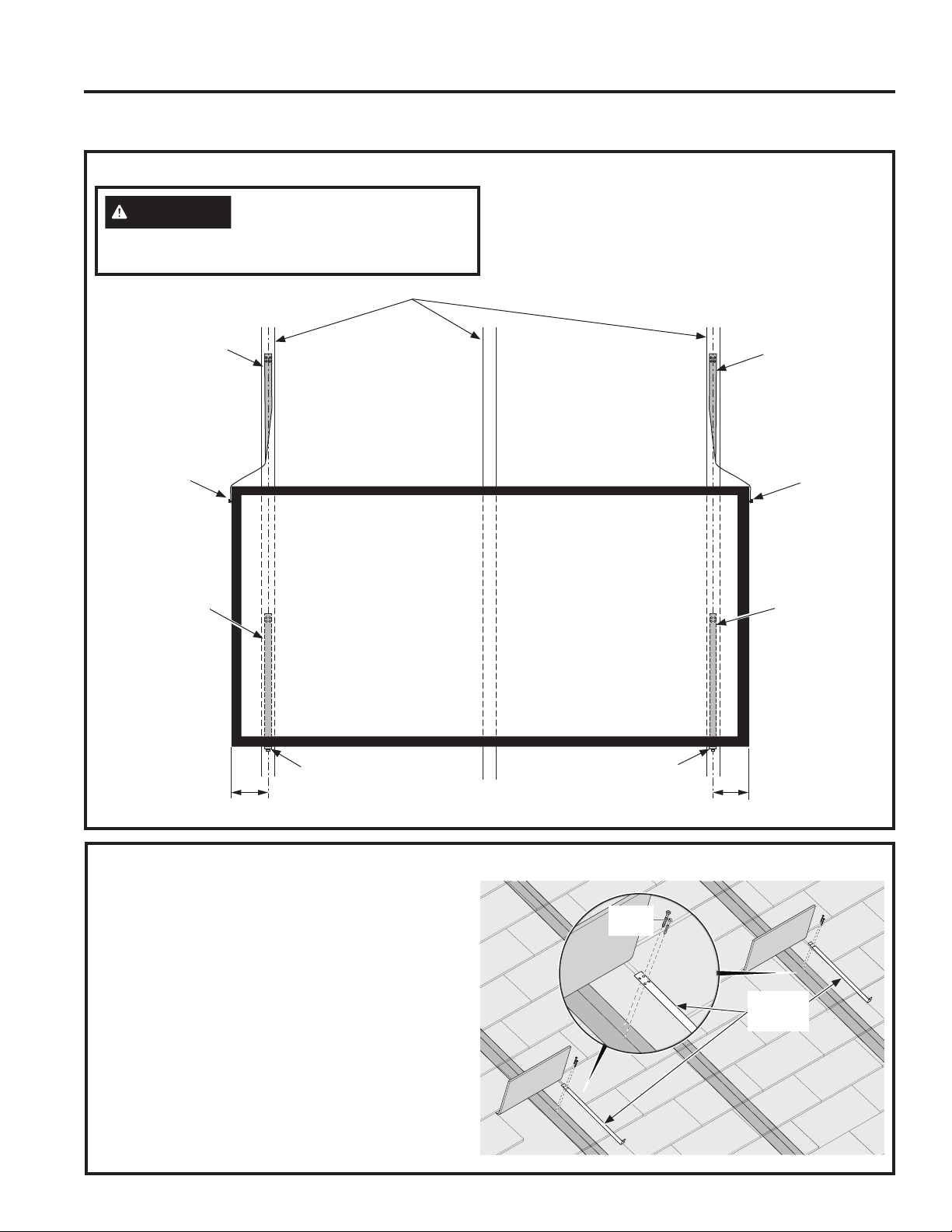
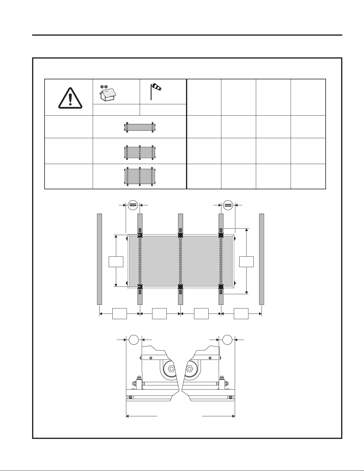
Installation Instructions
Attachment Point Recommendations
HIGH LOAD ROOF INSTALLATION
GeoSpring™
Solar 25
GeoSpring™
Solar 40
GeoSpring™
Solar 50
10.5
lb/ft²
121
19.4 ± 0.4
31.1 ± 0.4
42.7 ± 0.4
MPH
inch
A
inch
B
inch
C
24.0
35.5
47.25
32.0
32.0
32.0
inch
D
2.0
2.0
2.0
C C C C
A
B
GeoSpring Solar 25
GeoSpring Solar 40
GeoSpring Solar 50
DD
INSTALLATION INSTRUCTIONS
49-6000121 Rev. 0
INSTALLATION INSTRUCTIONS
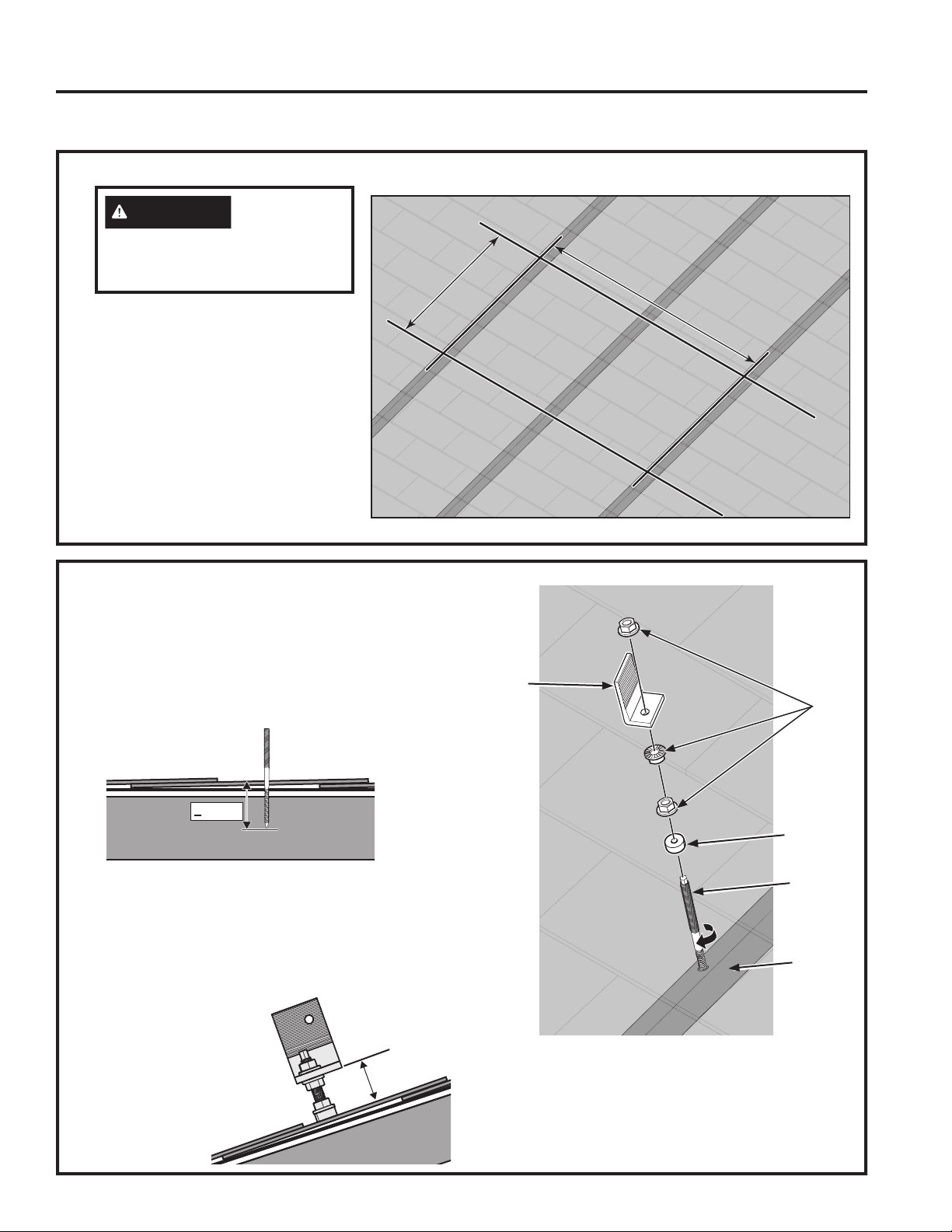
Installation Instructions
HIGH LOAD ROOF INSTALLATION
1. Locate Collector Panel
Ŷ'HWHUPLQHWKHORFDWLRQRIWKH
Collector Panel according to the
information on the previous page.
The brackets need to be installed
directly into a beam below roofing.
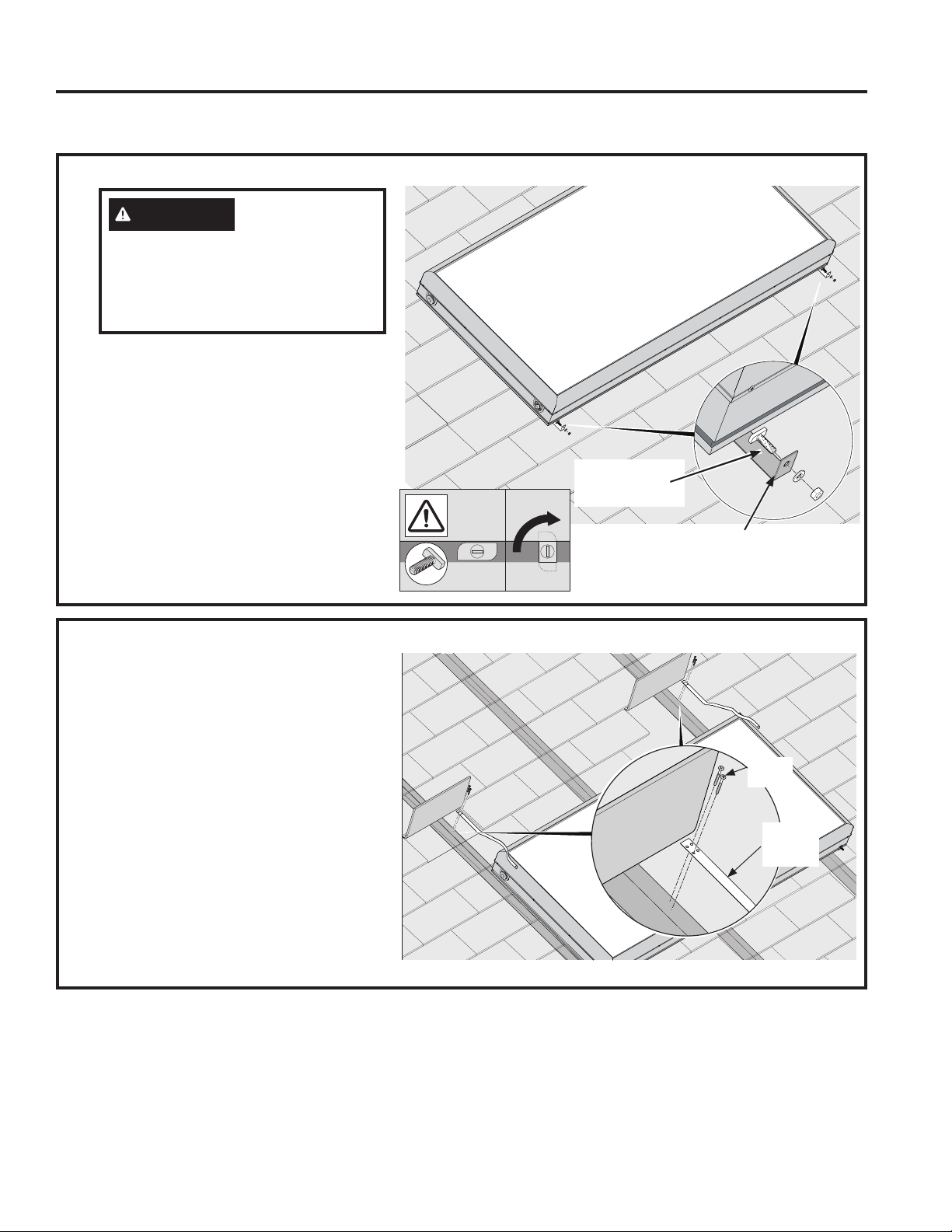
2. Install Collector Panel Brackets
Ŷ8VLQJDPPGULOOELWGULOOSLORWKROHVLQWRWKH
beams through the shingles for attaching the
brackets to the roof.
Ŷ,QVWDOOWKH0HWULF0[$QFKRULQWRWKH
beams making sure the anchor is no less than
ƎLQWRWKHEHDP
Ŷ,QVWDOOWKH5XEEHU%XVKLQJ1XWVDQG%UDFNHW
DVVKRZQIRUHDFKKROHGULOOHGKROHVIRU
*HR6SULQJKROHVIRU*HR6SULQJ
Each Bracket, once installed, should be a
PD[LPXPRIƎRIIRIWKHWRSRIWKHVKLQJOH
roofing. Bolts
should be
tightened to
IWOEV
Ŷ,QVWDOORU
EUDFNHWV
depending on
your model.
CAUTION
THE
FOLLOWING STEPS MUST BE
PERFORMED BY A LICENSED
ROOFING CONTRACTOR.
4.3 in.
>
max. 1.38"
Nut,
0
Mounting
Bracket
Rubber
Bushing
Anchor
Beam
32 49-6000121 Rev. 0
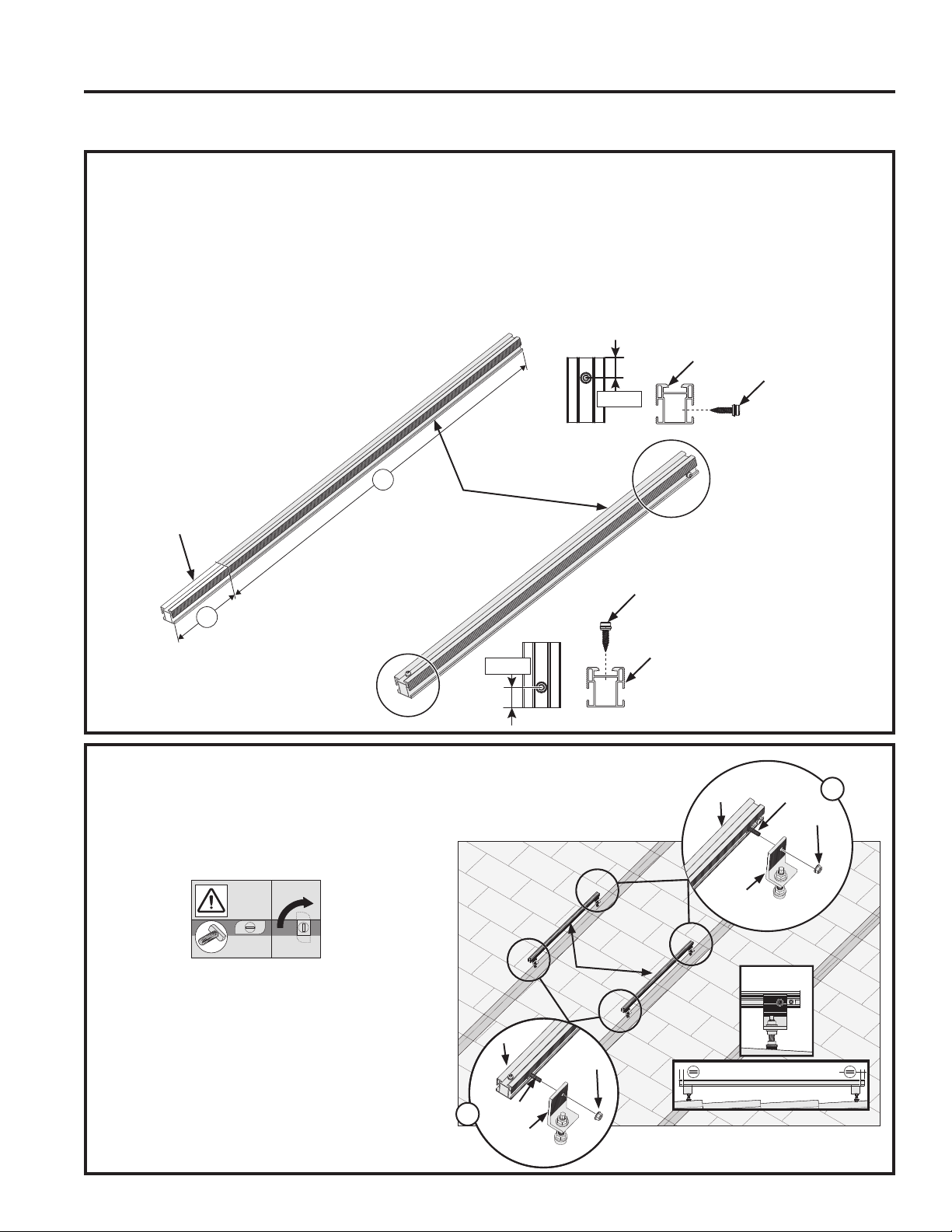
3. Assemble Mounting Rails
Ŷ'HWHUPLQHWKHOHQJWKRIUDLOQHHGHGIRU\RXU
installation. Cut off and discard the excess rail.
Ŷ,QVWDOOWKH6HOI7DSSLQJ6FUHZDVVKRZQRQHRQ
the top lower portion of the rail and one on the
right side of the upper portion of the rail. Position
WKH6HOI7DSSLQJ6FUHZƎIURPWKHHQGRI
the rail and tighten the screw
Ŷ)ROORZWKHVHVWHSVZLWKDOOUDLOV
Installation Instructions
HIGH LOAD ROOF INSTALLATION
4. Install Mounting Rails
Ŷ7KHPRXQWLQJUDLOVILWRQWRWKHPRXQWLQJ
brackets using T-Head Bolts. Place a
T-Head Bolt into the upper side of the rail to
WKHLQVLGHRIWKHEORFNDQGWXUQLWVRLWLV
secure in groove of the rail. 1
Place a T-Head Bolt into the lower side
RIWKHUDLODQGWXUQLWVRLWLVVHFXUHLQ
groove of the rail. 2 You can slide the bolts
up and down the rail so they accommodate
the mounting bracket.
Ŷ6OLGHWKHWKUHDGHGSRUWLRQRIWKHEROWLQWR
the mounting bracket that is installed on the
URRI6HFXUHXVLQJDQ00HWULF1XW
Ŷ5HSHDWWKLVVWHSZLWKDOOUDLOV
90°
X
B
0.78 in
0.78 in
Screw
Self-Tapping
Screw
Rail
Rails
Rail
Remove and
Discard
T-Head
Bolt
01XW
T-Head
Bolt
01XW
Rails
Rail
Mounting
Bracket
Rail
Mounting
Bracket
1
2
INSTALLATION INSTRUCTIONS
49-6000121 Rev. 0 33
INSTALLATION INSTRUCTIONS
Installation Instructions
HIGH LOAD ROOF INSTALLATION
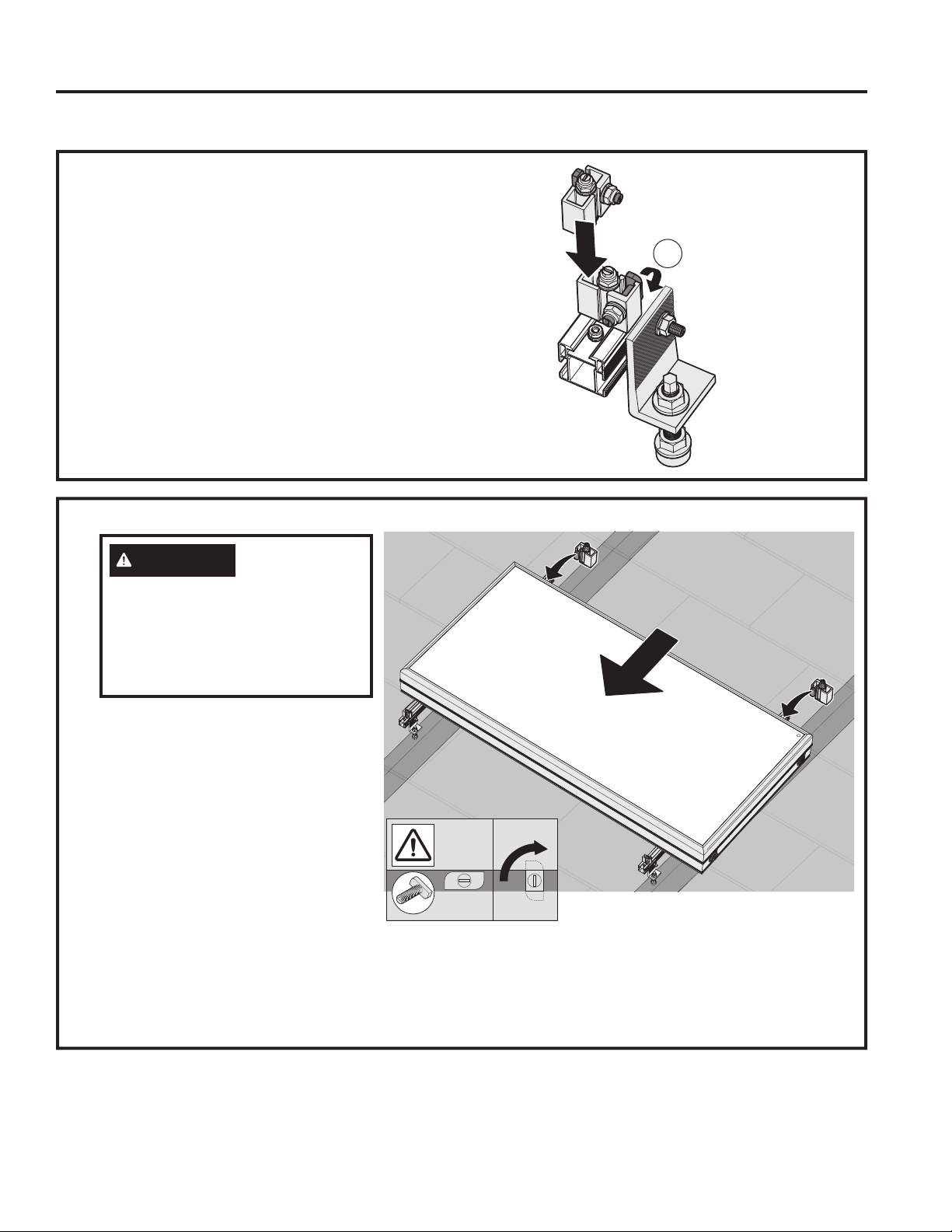
5. Install Lower High Load Brackets
Ŷ,QVWDOOD+LJK/RDG%UDFNHWRQWKHWRSRIWKH
lower portions of each rail. Set the bracket into
the groove in the rail above the self-tapping
VFUHZ7XUQWKH+LJK/RDG%UDFNHW
clockwise to lock into place. Install the lower
+LJK/RDG%UDFNHWRQDOOUDLOV
Ŷ7KH+LJK/RDG%UDFNHWKDVD7+HDG%ROW
LQVWDOOHG7XUQWKHEROWVRWKH7LVKRUL]RQWDO
and will fit into the groove of the collector panel.
90°
6. Place Collector Panel and Install Upper High Load Brackets
Ŷ3ODFHWKHFROOHFWRUSDQHORQWRWKHUDLOV
on the roof, sliding it down until it fits
XSDJDLQVWWKH+LJK/RDG%UDFNHWV
The T-Head Bolt should fit into the
groove in the front of the panel. Turn
WKH7+HDG%ROWVRLWZLOOORFNLQWR
panel. See figure.
Ŷ,QVWDOOD+LJK/RDG%UDFNHWRQWKHWRS
of the upper portions of each rails.
Set the bracket into the groove in the
UDLO7XUQWKH+LJK/RDG%UDFNHW
FORFNZLVHOLNH\RXGLGZLWKWKH/RZHU
+LJK/RDG%UDFNHW
Ŷ7KH+LJK/RDG%UDFNHWKDVD7+HDG%ROW
LQVWDOOHG7XUQWKHEROWVRWKH7LVKRUL]RQWDO
and will fit into the groove of the Collector Panel.
Ŷ6OLGHWKH+LJK/RDG%UDFNHWVRWKH7+HDG%ROW
fits into the groove of the Collector Panel. Turn
WKH7+HDG%ROWVRLWZLOOORFNLQWRWKHSDQHO
See figure.
WARNING
TO AVOID
BODILY HARM AND/OR
PROPERTY DAMAGE, HAVE TWO
PEOPLE JOINTLY INSTALL THE
PRODUCT.
FRAGILE PRODUCT – HANDLE
WITH CARE!
90°
34 49-6000121 Rev. 0
7. Final Installation Steps
Ŷ&RQQHFWWKHFROGZDWHULQOHWDQGILOOWKHFROOHFWRU
8VHWKHWKUHDGDGDSWRUVIRU86137WKUHDGV
5HIHUHQFH+\GUDXOLF&RQQHFWLRQDQGYHQWLODWLRQ
valve installation section)
Ŷ&RQQHFWWKHKRWZDWHURXWOHW
Ŷ5HPRYHWKHIRLOZLWKLQGD\VRILQVWDOOLQJWKH
GeoSpring Solar system but never before the
system is filled!
NOTICE: Risk of Unit Damage
Do NOT insulate combined non-return/safety
valve or ventilation valve. The water heater
warranty does not cover damage or failure
resulting from operation with insulated
valves.
NOTICE:
Do not use more than 30 ft-lbs torque!
NOTICE:
Do not use more than 30 ft-lbs torque!
Installation Instructions
HIGH LOAD ROOF INSTALLATION
)ODW6HDO)DFWRU\,QVWDOOHG
Flat Seal
Hot Water
Outlet
9HQWLODWLRQ9DOYH
+RW:DWHU
Cold Water
Inlet
INSTALLATION INSTRUCTIONS
49-6000121 Rev. 0 35
INSTALLATION INSTRUCTIONS
Installation Instructions
INSTALLATION CHECKLIST
1. Installation has sufficient load bearing capacity and in accordance with local and regional codes.
2. Installed in accordance with these instructions, local, and regional codes.
3. Inspected substructure for retaining screw connections used to secure installation.
4. ,QOHW2XWOHWFRQQHFWLRQVWLJKWHQHGWRIWOEV
5. Collector loop piping is secured and allows for expansion/contraction.
6.3LSLQJFDQZLWKVWDQG)
7. No connections between copper and stainless steel.
8.6XSSO\DQGUHWXUQVOLQHVLQVXODWHGDQGSURWHFWHGIURP89GHJUDGDWLRQ
9.9DOYHVDUH127LQVXODWHG
10.,QVWDOOHGV\VWHPKDVDQLQFOLQDWLRQEHWZHHQWR
11. Combined non-return/safety valve is working and drain line completed per local code.
12. No leaks after filling the tank with water, either when water is flowing or not.
13.:DWHUTXDOLW\PHHWVVSHFLILFDWLRQVRQSDJH
14. South facing installation with minimized shading.
49-6000121 Rev. 0
Troubleshooting
TROUBLESHOOTING
Before you call for service....
Save time and money! Review the chart below first and you may not need to call for service.
CAUTION
For your safety, DO NOT attempt repair of electrical wiring, controls, heating elements or
other safety devices. Refer repairs to qualified service personnel.
Problem Possible Causes
What To do
OPERATION AND PERFORMANCE
Not enough or no hot
water
Water temperature may
be set too low
• See the Water Temperature Adjustment and Water Heater
&DSDFLW\VHFWLRQV3DJHV
Hot water usage pattern
exceeds the capability of
the water heater in current
mode
• Wait for the water heater to recover.
Cold water inlet
temperature may be
colder during the winter
months
• This is normal. The colder inlet water takes longer to heat.
• Consider increasing the set temperature as described in the
Water Temperature Adjustment section.
Leaking or open hot
water faucets
• Make sure all faucets are closed.
Long runs of exposed
pipe, or hot water piping
on outside wall
• Insulate piping.
Water Connections to
unit reversed
• Correct piping connections.
Recirculating System
Interference (if installed)
• Check flow rate is not set too high.
• Insulate piping
Check installation
is south facing with
minimized shading
• Correct installation to face south and minimize shading
Water is too hot Water temperature is set
too high
• See the Water Temperature Adjustment section.
Mixing valve has failed • Contact your local installer, plumbing contractor, or
previously agreed upon service agency.
OTHER
Water dripping down the
outside of the heater
Hot/Cold water connections
or other parts have loosened
• Tighten the loose connections. This should only be done by a
qualified service person.
Combined non-return/
safety valve producing
popping sound or
draining
Pressure buildup caused
by thermal expansion to a
closed system
• This is an unacceptable condition and must be corrected. See
7KHUPDO([SDQVLRQVHFWLRQRQSDJH'RQRWSOXJWKHUHOLHIYDOYH
outlet. Contact your local installer, plumbing contractor, or previously
agreed upon service agency to correct this.
The combined non-return/
safety valve will open at 72
PSI
Reduce system water pressure
Water Not Filling Heater Cold Water supply is off Check all valves to ensure system can be filled with water
Combined non-return/safety
valve
The combined non-return/safety valve has a check valve integrated.
If installed backwards, flow can be prevented from filling the water
heater.
49-6000121 Rev. 0
Replacement Parts
REPLACEMENT PARTS
For GeoSpring
TM
Solar models.
Instructions for Placing a Parts Order
All parts orders should include:
7KHPRGHODQGVHULDOQXPEHURIWKHZDWHUKHDWHUIURP
the rating plate
2. Specify voltage and wattage as marked on the rating
SODWHLIVSHFLILHG
3DUWGHVFULSWLRQDVQRWHGEHORZDQGQXPEHURISDUWV
desired.
CAUTION
For your safety, DO NOT attempt
repair of electrical wiring, thermostat(s), heating
elements or other operating controls. Refer to
qualified service personnel.
Appearance may vary by model
Combined non-
return/safety valve
NPT Thread
Adapter
Casing
8SSHU
Caps and
o-rings
9HQWLODWLRQ
9DOYH
49-6000121 Rev. 0
SRCC OG-300 Certification
CERTIFICATION
The solar system installer is to indicate (circle, check, etc.) the system that was actually installed.
This product certified by:
Solar Rating & Certification
Corporation™
Solar-Rating.org
GE Appliances, A Haier Company
4000 Buechel Bank Road
Louisville, KY 40225 USA
Solar Energy
Factor (SEF
D)
SRCC Cert. No. Model No.
*7&%$07*
*7&%$07*
*7&%$07*
*7&%$0(
*7&%$0(
*7&%$0(
*7&%$0*
*7&%$0*
*7&%$0*
The installed system is marked above
The solar energy system described by this manual, when properly installed and maintained, meets the minimum
standards established by the ICC-SRCC. This certification does not imply endorsement or warranty of this product by
ICC-SRCC.

49-6000121 Rev. 0
CERTIFICATION
THIS PAGE INTENTIONALLY LEFT BLANK
SRCC OG-300 Certification
49-6000121 Rev. 0
The following labels/tags must be attached to the relevant valves in the systems in order for it to be considered
2*FRPSOLDQWThis page should be laminated, each label cut from it, punched in the margin on the left-
hand side and affixed to the appropriate valve with a wire tie. Plastic ties are inappropriate due to high operating
WHPSHUDWXUHVDQG89UDGLDWLRQ)DLOXUHWRDIIL[WKHVHODEHOVZLOOYRLGWKH65&&2*FHUWLILFDWLRQ
SRCC OG-300 Certification
CERTIFICATION
COMBINED NON-RETURN/SAFETY VALVE
This valve is a pressure release mechanism used in pressure systems. It has a non-return valve integrated. The
XVHRIWKHVHYDOYHVLVVWULFWO\UHTXLUHGGXHWRVDIHW\UHJXODWLRQV7KHVDIHW\YDOYHRSHQVDWDSUHVVXUHRI36,WR
reduce excess pressure.
Valve must be replaced by year five to gain the limited warranty for years six through ten.
WARNING
BURN HAZARD
Do NOT touch hot water outlet pipes. Failure to do so can result in severe burns.
2
VENTILATION VALVE
This valve ensures that no vacuum is created when draining the water tank.
In the event of negative pressure, the ventilation valve automatically supplies the system with air.
7KLVYHQWLODWLRQYDOYHPXVWFRPSO\ZLWK$16,=
Valve must be replaced by year five to gain the limited warranty for years six through ten.
WARNING
BURN HAZARD
Do NOT touch hot water outlet pipes. Failure to do so can result in severe burns.
4
COLD WATER SUPPLY ISOLATION VALVE
This valve should stay open to allow water from the public water system to fill the GeoSpring Solar System
water tank. When this valve is closed, the GeoSpring Solar System and the supplemental water heater are
disconnected from the pressurized mains of the public water system.
5
HOT WATER SUPPLY ISOLATION VALVE
Keep this valve open to assure that hot water can drain or escape in case of overheating. This valve can
temporarily be closed for maintenance purposes.
DRAIN VALVE
7KHVHZDWHUKHDWHUGUDLQVDUHQRUPDOO\FORVHGDQGFDSSHG8VHWKHVHYDOYHVWRGUDLQWKH*HR6SULQJ6RODU
System. Attach a garden hose to both drain valves. Terminate the hoses in either a service basin or an
appropriate spot outside the house. Open both water heater drains at once to drain the unit.
WARNING
SCALD RISK
WATER MAY BE DISCHARGED AT VERY HIGH TEMPERATURES. TO AVOID SCALDING, EXERCISE
MAXIMUM CAUTION WHEN DRAINING THE HOT WATER FROM THE GEOSPRING SOLAR SYSTEM. DO
NOT POINT HOSE AT PERSONS OR PETS. ALWAYS DISCHARGE THE HOT WATER TO A SAFE PLACE.
THERMOSTATIC MIXING VALVE
This valve controls the temperature of the warm water output. According to local standards, the valve must have
a scald safe function. Scald safe means that in the case of a cold water failure, the hot water supply shuts off
automatically.
$Q$66(UDWHGPL[LQJYDOYHWRDYRLGVHYHUHEXUQVRUGHDWKIURPVFDOGLQJWHPSHUDWXUHV,65(48,5('3(5
65&&2*
PRESSURE REDUCING VALVE
7KLVYDOYHVKRXOGHQVXUHDFRQVWDQWRXWSXWSUHVVXUHRI36,LQGHSHQGHQWRIWKHLQSXWSUHVVXUHGHOLYHUHGIURP
any source.
3 WAY BALL VALVE
This valve provides solar system cold water shut off without interrupting normal cold water service.

49-6000121 Rev. 0
CERTIFICATION
THIS PAGE INTENTIONALLY LEFT BLANK
SRCC OG-300 Certification
42 49-6000121 Rev. 0
Freeze Protection
7KHIROORZLQJODEHOVPXVWEHDWWDFKHGWRWKHUHOHYDQWYDOYHVLQWKHV\VWHPVLQRUGHUIRULWWREHFRQVLGHUHG2*
compliant. This page should be laminated, each label cut from it, punched in the margin on the left-hand
side and affixed to the appropriate valve with a wire tie. Plastic ties are inappropriate due to high operating
WHPSHUDWXUHVDQG89UDGLDWLRQ)DLOXUHWRDIIL[WKHVHODEHOVZLOOYRLGWKH65&&2*FHUWLILFDWLRQ
7KH*HR6SULQJ6RODU6\VWHPPD\EHLQVWDOOHGLQDUHDVZLWKLQWKH8QLWHG6WDWHVWKDWH[SHULHQFHPLOGZLQWHU
climates. However, the GeoSpring Solar System must be drained if the temperatures have ever fallen to 32ºF for 8
consecutive hours.
When these environmental conditions are lower than the stated value, the GeoSpring Solar System must be manually
drained in accordance with the Care and Cleaning instructions. Failure to do so will void the warranty coverage.
SRCC OG-300 Certification
CERTIFICATION
Freeze Protection:
32ºF for 8 consecutive hours
When these environmental conditions are lower than the stated value, the GeoSpring Solar System must be
manually drained in accordance with the Care and Cleaning instructions.
Drain Procedure:
VALVE 4 &2/':$7(56833/<,62/$7,219$/9(
VALVE 6 '5$,19$/9(
9DOYHLVQRUPDOO\RSHQDQGDOORZVFROGZDWHUWRILOOWKH*HR6SULQJ6RODU6\VWHP:KHQWKHYDOYHLVFORVHGWKH
GeoSpring Solar System is isolated from the pressurized cold water supply line piping. To drain the system, open
YDOYH
WARNING
SCALD RISK
WATER MAY BE DISCHARGED AT VERY HIGH TEMPERATURES. TO AVOID SCALDING, EXERCISE
MAXIMUM CAUTION WHEN DRAINING THE HOT WATER FROM THE GEOSPRING SOLAR SYSTEM. DO
NOT POINT HOSE AT PERSONS OR PETS. ALWAYS DISCHARGE THE HOT WATER TO A SAFE PLACE.

49-6000121 Rev. 0 43
CERTIFICATION
THIS PAGE INTENTIONALLY LEFT BLANK
SRCC OG-300 Certification
44 49-6000121 Rev. 0
CERTIFICATION
Labeling for all fill and drain ports:
7KHIROORZLQJODEHOVPXVWEHDWWDFKHGWRWKHUHOHYDQWYDOYHVLQWKHV\VWHPVLQRUGHUIRULWWREHFRQVLGHUHG2*
complaint. This page should be laminated, each label cut from it, punched in the margin on the left-hand
side and affixed to the appropriate valve with a wire tie. Plastic ties are inappropriate due to high operating
WHPSHUDWXUHVDQG89UDGLDWLRQ)DLOXUHWRDIIL[WKHVHODEHOVZLOOYRLGWKH65&&2*V\VWHPFHUWLILFDWLRQ
SRCC OG-300 Certification
No other fluid shall be used that would change the original classification of this system.
8QDXWKRUL]HGDOWHUDWLRQVWRWKLVV\VWHPFRXOGUHVXOWLQDKD]DUGRXVKHDOWKFRQGLWLRQ
WARNING
SCALD RISK
WATER MAY BE DISCHARGED AT VERY HIGH TEMPERATURES. TO AVOID SCALDING, EXERCISE
MAXIMUM CAUTION WHEN DRAINING THE HOT WATER FROM THE GEOSPRING SOLAR SYSTEM. DO
NOT POINT HOSE AT PERSONS OR PETS. ALWAYS DISCHARGE THE HOT WATER TO A SAFE PLACE.

49-6000121 Rev. 0 45
CERTIFICATION
THIS PAGE INTENTIONALLY LEFT BLANK
SRCC OG-300 Certification
49-6000121 Rev. 0
GE Appliances Solar Water Heater Limited Warranty
Staple your receipt here. Proof of the original purchase
date is needed to obtain service under the warranty.
What Is Not Covered:
Service trips to your home to teach you how to use
the product.
Improper installation, delivery or maintenance.
Failure of the product if it is abused, misused, altered, or
used for other than the intended purpose.
Use of this product where water is microbiologically unsafe
or of unknown quality, without adequate disinfection before
or after the system.
Replacement of house fuses or resetting of circuit breakers.
Damage to the product caused by accident, lightning, fire,
flood or acts of God.
Incidental or consequential damage caused by possible
defects with this appliance, its installation or repair.
Product not accessible to provide required service
in a safe
manner. Attic installation must have flooring and accessible
stairs.
If product removed from original installation location.
If product or other appliance must be moved for service
access.
Damage, malfunction or failure caused by the use of repair
service not approved by GE Appliances.
Damages, malfunctions or failure caused by the use of
unapproved parts or components.
Damages, malfunctions or failure resulting from operating
the water heater with an empty or partially empty tank.
Damages, malfunctions or failure caused by subjecting the
tank to pressure greater than those shown on the rating
label.
Water heater failure due to the water heater being operated
in a corrosive atmosphere.
If this Solar Water Heater is used for other than residential
private family use, labor will not be covered under warranty,
and the parts warranty is reduced to 1 year from the date of
purchase.
Harmful chemicals, caustic fluids, or liquids deleterious to
steel tubing, including improperly applied or maintained
heat transfer fluids, or chlorinated pool or spa water
Water related corrosion
Clouding or condensation naturally resulting from
temporary intrusions of moisture into the product.
Water freezing in tanks, pipes, or other product components
Breakage of glass surface of any product component
EXCLUSION OF IMPLIED WARRANTIES—Your sole and exclusive remedy is product repair as provided
in this Limited Warranty. Any implied warranties, including the implied warranties of merchantability or
fitness for a particular purpose, are limited to one year or the shortest period allowed by law.
LIMITED WARRANTY
This limited warranty is extended to the original purchaser and any succeeding owner for products purchased for
KRPHXVHZLWKLQWKH86$,IWKHSURGXFWLVORFDWHGLQDQDUHDZKHUHVHUYLFHE\DQLQVWDOOHUSOXPELQJFRQWUDFWRU
or previously agreed upon service agency is not available, you may be responsible for a trip charge to the service
provider.
Some states do not allow the exclusion or limitation of incidental or consequential damages. This limited warranty
gives you specific legal rights, and you may also have other rights which vary from state to state. To know what your
legal rights are, consult your local or state consumer affairs office or your state’s Attorney General.
For product purchased outside of the US, contact your dealer for Warranty and Service information.
Warrantor for Products Purchased in the United States:
GE Appliances, a Haier company
Louisville, KY 40225
All warranty service provided by our Authorized Servicer Network.
For The Period Of: We Will Replace:
One Year
From the date of the
original purchase
Any part of the Water Heater which fails due to a defect in materials or workmanship.
During this limited one-year warranty, GE Appliances will reimburse registered service
providers, or will reimburse consumers for documented out of pocket costs for parts and/
or labor for professional service at a predetermined rate as found on the GE Appliances
Website: GEAppliances.com/waterheater, unless service provided to replace defective parts is
determined to be a result of improper installation or maintenance.
Second through Fifth
Year From the date of
the original purchase
Any part of the Water Heater which fails due to a defect in materials or workmanship. During
this limited second through year five warranty period, labor and related service to replace
the defective part are not included.
Sixth through Tenth
Year From the date of
the original purchase
RIWKHFRVWRIany part of the water heater which fails due to a defect in materials or
workmanship. During this limited sixth through the end of the warranty period, labor
and related service to replace the defective part are not included.
:DUUDQW\LVEDVHGRQWKHWKDQGWKGLJLWRIPRGHOQXPEHUORFDWHGRQUDWLQJSODWHHJ*7&10BAM has a part
ZDUUDQW\RI\HDUV

49-6000121 Rev. 0
NOTES
Notes
49-6000121 Rev. 0
Printed in Austria
Consumer Support
CONSUMER SUPPORT
Register Your Appliance
Register your new appliance on-line at your convenience! Timely product registration will allow for enhanced
communication and prompt service under the terms of your warranty, should the need arise.
• Scan QR Code on product registration card, or on product.
NOTE: This is just an example of what a QR code represents.
• Or go to GEAppliances.com/register
• Or mail in your pre-printed registration card included in the packing material
Consumer Service
If you have a question or need assistance with your new water heater on adjustments, repairs, or routine
maintenance:
• Review the Troubleshooting Tips or Care and Cleaning sections of this Owner’s Manual.
• Contact your local installer, plumbing contractor, or previously agreed upon service agency.
NOTE: Your installer phone number may be located on the product label.
If you still have issues, contact the GEA Customer Support at GEAppliances.com/waterheater
Parts and Accessories
Individuals qualified to service their own appliances can have parts or accessories sent directly to their homes.
9,6$0DVWHU&DUGDQG'LVFRYHUFDUGVDUHDFFHSWHG2UGHURQOLQHWRGD\KRXUVHYHU\GD\
,QWKH86JRWR*($SSOLDQFHSDUWVFRP
Contact Us
If you are ultimately not satisfied with the service you receive, contact us on our Website with all the details including
your phone number, or write to:
,QWKH86*HQHUDO0DQDJHU&XVWRPHU5HODWLRQV_*($SSOLDQFHV$SSOLDQFH3DUN_/RXLVYLOOH.<
GEAppliances.com/contact
Extended Warranties
Purchase a GE Appliances extended warranty and learn about special discounts that are available while your
warranty is still in effect. You can purchase it on-line anytime. GE Appliances Services will still be there after your
ZDUUDQW\H[SLUHV,QWKH86GEAppliances.com/extended-warranty RUFDOOGXULQJQRUPDOEXVLQHVV
hours.