Accessories
4
Inserting the batteries
5
Operating range of the remote control unit
5
Features
6
High quality sound
6
High performance
6
Part names and functions
7
Front panel
7
Rear panel
10
Remote control unit
12
Connections
Connecting speakers
17
Speaker connection
19
Bi-wiring connection
20
Connecting a playback device
21
Connecting a recording device
22
Connecting to a device with digital audio output connectors
23
Connecting a PC or Mac
24
Connecting the power cord
25
Playback
Turning the power on
27
Selecting the input source
28
Adjusting the volume
28
Turning off the sound temporarily (Muting)
28
Adjusting the tone
28
Switching the display’s brightness
29
Playing CDs
29
Connecting and playing back from a computer (USB-DAC)
31
Connecting and playing back from a digital device (Coaxial/
Optical)
40
Recording
41
Settings
Setting the Auto Standby mode
42
Turning Auto Standby mode on
42
Turning Auto Standby mode off
42
Contents Connections Playback Settings Tips Appendix
2
Front panel Rear panel
Remote control
unit
Index
Thank you for purchasing this Denon product. To ensure proper operation, please read this owner’s manual carefully before using the product.
After reading this manual, be sure to keep it for future reference.
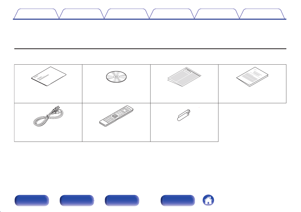
Accessories
Check that the following parts are supplied with the product.
.
Quick Start Guide
CD-ROM
(Owner’s Manual)
Safety Instructions
Remote control unit
(RC-1213)
R03/AAA batteries
Power cord
Warranty
(for North America model only)
Contents Connections Playback Settings Tips Appendix
4
Front panel Rear panel
Remote control
unit
Index
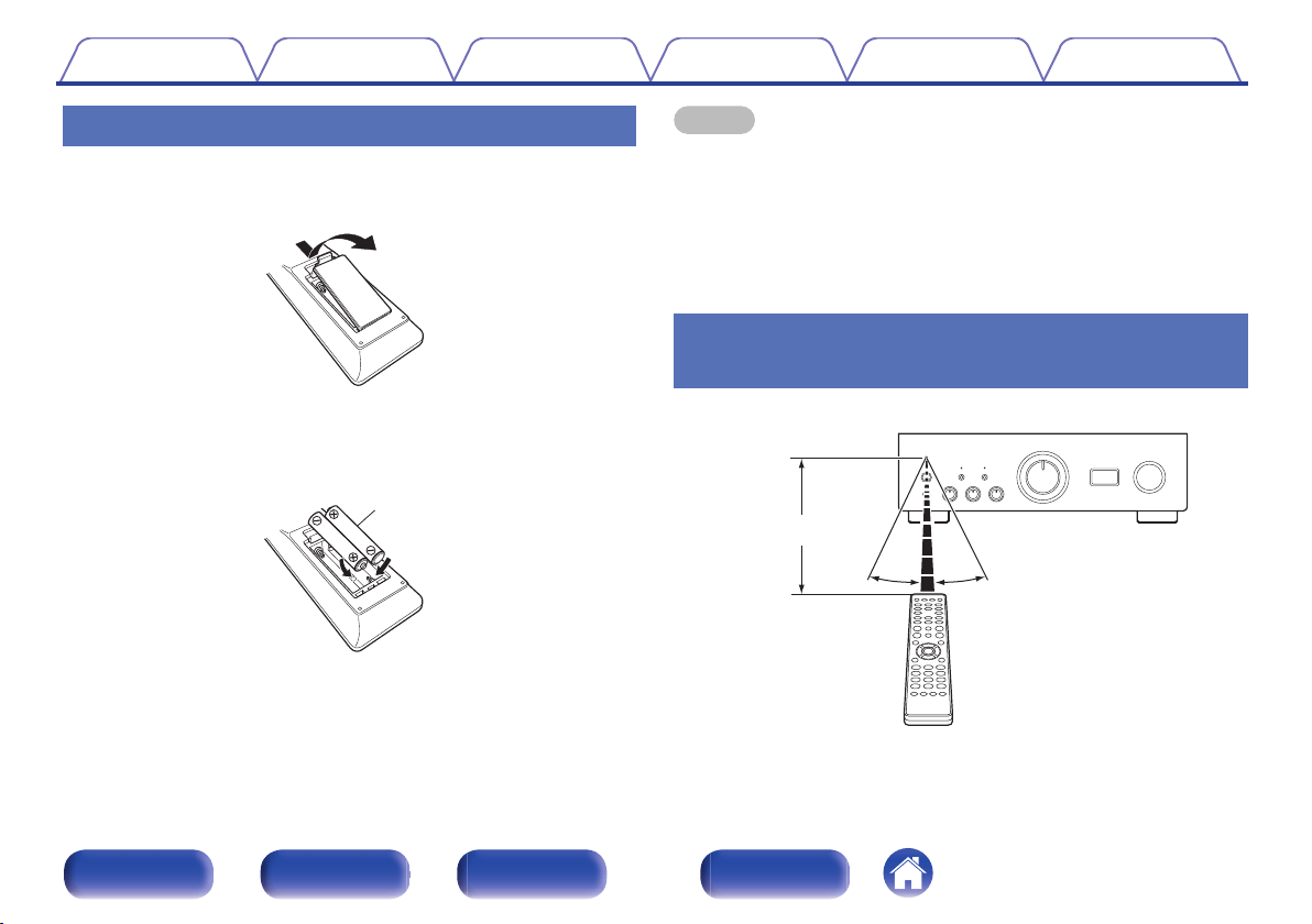
Inserting the batteries
1
Remove the rear lid in the direction of the arrow and
remove it.
.
2
Insert two batteries correctly into the battery
compartment as indicated.
.
Batteries
3
Put the rear cover back on.
NOTE
0
To prevent damage or leakage of battery fluid:
0
Do not use a new battery together with an old one.
0
Do not use two different types of batteries.
0
Remove the batteries from the remote control unit if it will not be in use for long
periods.
0
If the battery fluid should leak, carefully wipe the fluid off the inside of the battery
compartment and insert new batteries.
Operating range of the remote control
unit
Point the remote control unit at the remote sensor when operating it.
.
30°
Approx. 23 ft/7 m
30°
Contents
Connections Playback Settings Tips Appendix
5
Front panel Rear panel
Remote control
unit
Index
Features
High quality sound
0
Advanced UHC-MOS Single Push-pull Circuit
The UHC-MOS FET is employed for the power amplifier output stage.
The steady current is 30 A and the instantaneous current is 120 A. The
operation stability affected by the temperature fluctuation is improved by
using the dual FET selected first stage for the voltage amplifier stage.
Furthermore, the phase property is stabilized up to the high range by
using the cascade bootstrap circuit.
0
Power Supply
To make the most of the Advanced UHC-MOS Single Push–pull Circuit,
this powerful power supply consists of a LC mount twin transformer,
schottky barrier diodes that have high current capacity, and a custom
block type capacitor that is tuned for high-quality sound.
0
Mechanical Ground
A chassis that has 6 discrete blocks shielded for each signal level and a
foot made of high density materials pursue the Mechanical Ground
concept, eliminating the influences caused by external vibration and
preventing vibration of the transformer, the internal vibration source,
from being transmitted to the amplifier circuit.
High performance
0
Equipped with a USB-DAC function to support playback of high-
resolution sound sources
This unit supports the playback of high resolution audio formats such as
DSD (2.8/5.6/11.2 MHz) and PCM files up to 384 kHz/32 bits. It
provides high quality playback of high resolution files into this unit from a
computer via USB-B connection.
0
DIGITAL AUDIO IN connectors (COAXIAL/OPTICAL)
You can play back PCM signals up to 192 kHz/24 bits by inputting digital
audio signals from an external device into this unit.
0
Phono Equalizer
Even a user who is particular about analog records is satisfied because
the Phono Equalizer circuit for the FET input supports MM/MC.
Contents
Connections Playback Settings Tips Appendix
6
Front panel Rear panel
Remote control
unit
Index
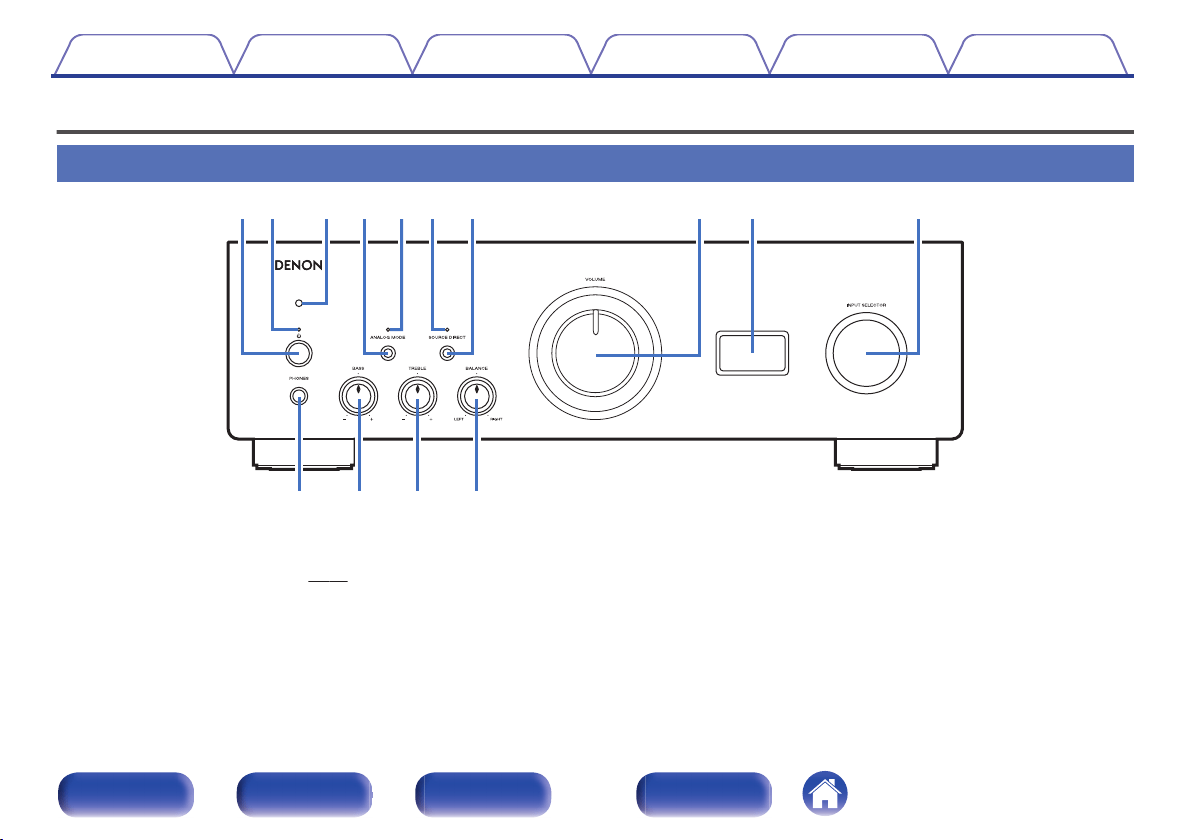
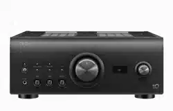
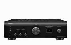
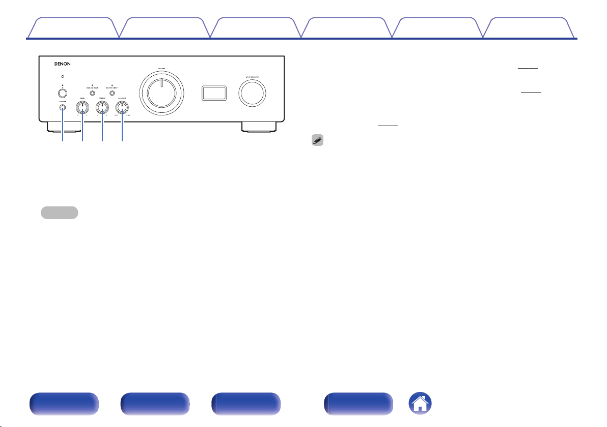
Part names and functions
Front panel
.
ru Q0eqw
yo
t
i
Q3 Q4Q2Q1
A
Power operation button (X)
This turns the power on/off. (v p. 27)
B
Power indicator
This is lit as follows according to the power status:
0
Power on : Green
0
Standby : Off
0
Power off : Off
0
When the protection circuit is activated : Red (blinking)
Contents
Connections Playback Settings Tips Appendix
7
Front panel Rear panel
Remote control
unit
Index
.
ru Q0e
yo
t
i
C
Remote control sensor
This receives signals from the remote control unit. (v
p. 5)
D
ANALOG MODE button
This switches the ANALOG MODE. (v p. 30)
E
ANALOG MODE indicator
This is lit as follows according to the ANALOG MODE status:
0
ANALOG MODE 1/2: Green
0
ANALOG MODE off: Off
F
SOURCE DIRECT indicator
This is lit as follows according to the SOURCE DIRECT status:
0
SOURCE DIRECT mode on: Green
0
SOURCE DIRECT mode off: Off
G
SOURCE DIRECT button
This turns SOURCE DIRECT mode on/off. (v
p. 29)
H
VOLUME knob
These adjust the volume level. (v
p. 28)
I
Display
This displays information such as the input source name, type of digital
audio signal and sampling frequency.
J
Input source select knob (INPUT SELECTOR)
This selects the input source. (v
p. 28)
Contents
Connections Playback Settings Tips Appendix
8
Front panel Rear panel
Remote control
unit
Index
.
Q
3
Q
4
Q
2
Q
1
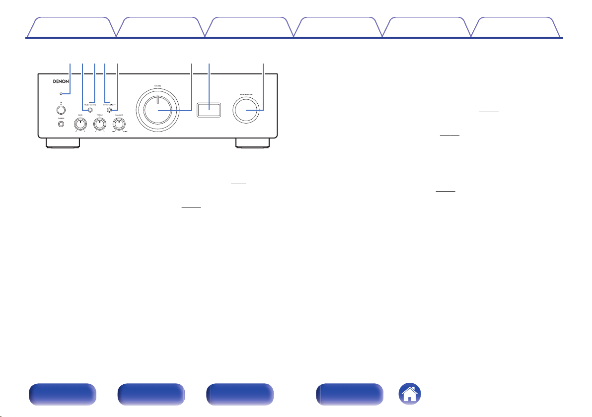
K
Headphones jack (PHONES)
Used to connect headphones.
Turn off speaker output when using headphones.
NOTE
0
To prevent hearing loss, do not raise the volume level excessively when using
headphones.
L
BASS control knob
This setting adjusts the volume level for the bass. (v
p. 28)
M
TREBLE control knob
This setting adjusts the volume level for the treble. (v p. 28)
N
BALANCE control knob
This adjusts the balance of the volume output from the left and right
speakers. (v
p. 28)
0
b, c and d can be adjusted when 7 is off (SOURCE DIRECT mode is off).
Contents Connections Playback Settings Tips Appendix
9
Front panel Rear panel
Remote control
unit
Index
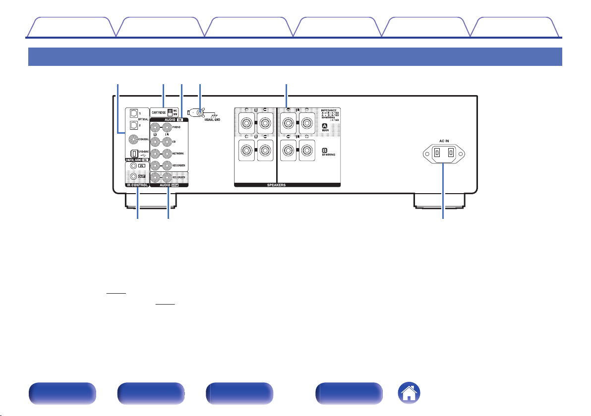
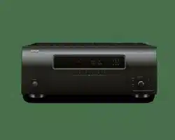
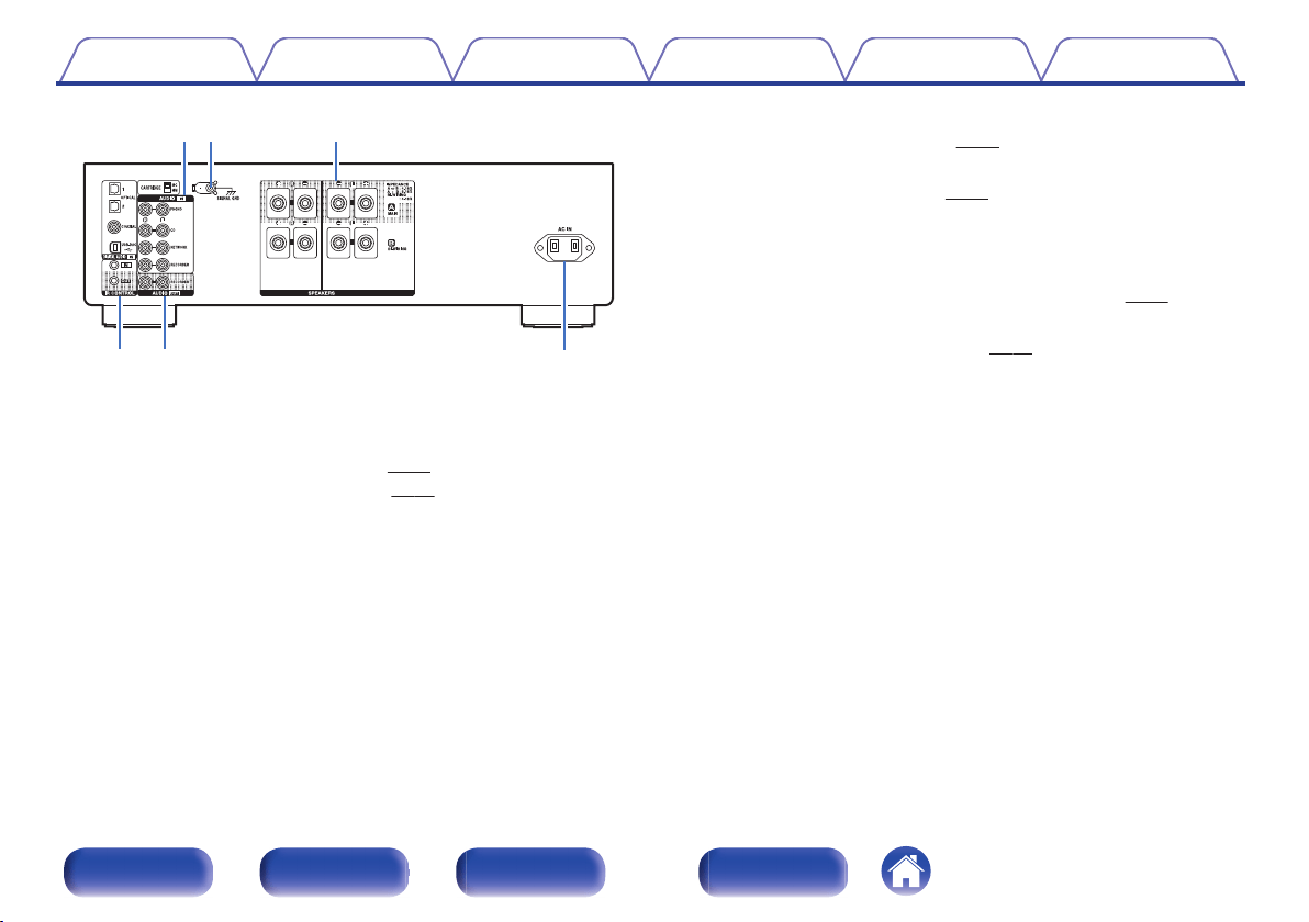
Rear panel
.
y ui
terqw
A
DIGITAL AUDIO IN connectors
Used to connect devices equipped with digital audio output connectors
and computer.
0
“Connecting to a device with digital audio output
connectors” (v
p. 23)
0
“Connecting a PC or Mac” (v p. 24)
B
CARTRIDGE selection switch
Set this switch to MM or MC according to the type of cartridge used on
your turntable.
Contents Connections Playback Settings Tips Appendix
10
Front panel Rear panel
Remote control
unit
Index
.
ter
i
yu
C
AUDIO IN connectors
Used to connect devices equipped with analog audio connectors.
0
“Connecting a playback device” (v
p. 21)
0
“Connecting a recording device” (v p. 22)
D
SIGNAL GND terminal
Used to connect a turntable. (v
p. 21)
E
Speaker terminals (SPEAKERS)
Used to connect speakers. (v p. 17)
F
IR CONTROL connectors
Used to connect Denon network audio players with an IR controller.
G
AUDIO OUT connectors
Used to connect the input connector of a recorder. (v
p. 22)
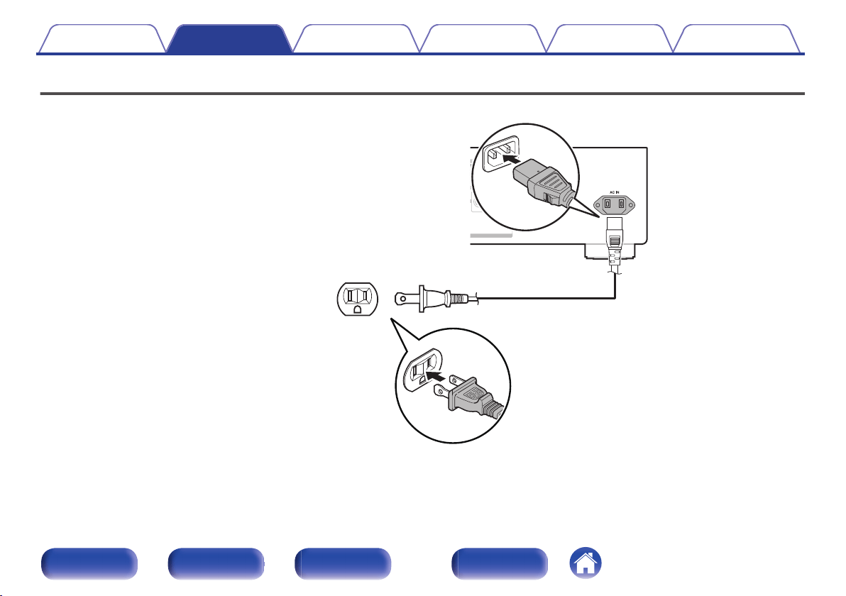
H
AC inlet (AC IN)
Used to connect the power cord. (v
p. 25)
Contents Connections Playback Settings Tips Appendix
11
Front panel Rear panel
Remote control
unit
Index
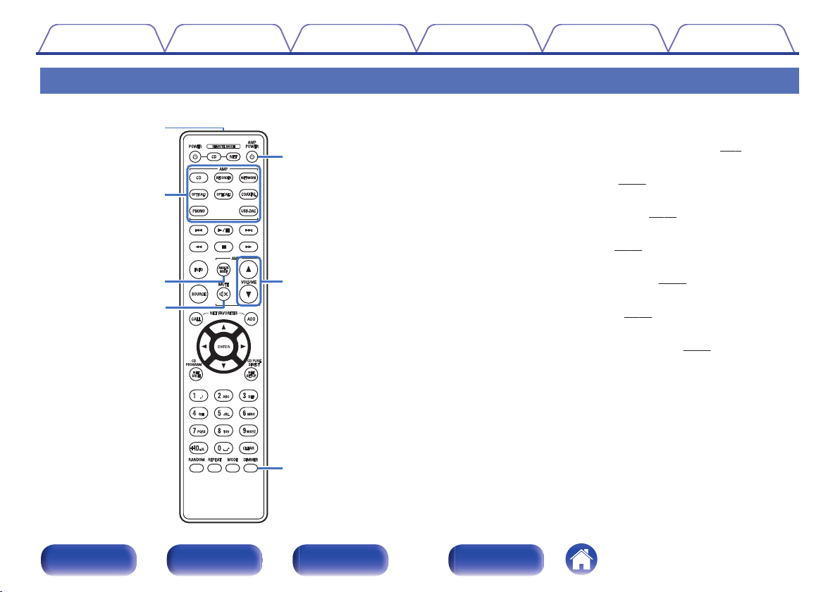
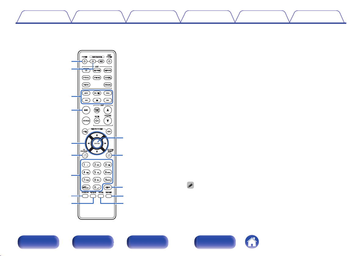
Remote control unit
.
w
e
r
t
y
u
q
o
Operating this unit
A
Remote control signal transmitter
This transmits signals from the remote control unit. (v
p. 5)
B
Input source select buttons
This selects the input source. (v p. 28)
C
ANALOG MODE button
This switches the ANALOG MODE. (v
p. 30)
D
MUTE button (:)
This mutes the output audio. (v
p. 28)
E
Power operation button (AMP POWER X)
This turns the power on/off (standby). (v p. 27)
F
VOLUME buttons (df)
These adjust the volume level. (v
p. 28)
G
DIMMER button
This switches the brightness of the display. (v p. 29)
Contents
Connections Playback Settings Tips Appendix
12
Front panel Rear panel
Remote control
unit
Index
w
e
q
r
u
i
o
t
y
Q2
Q1
Q3
Q4
Q0
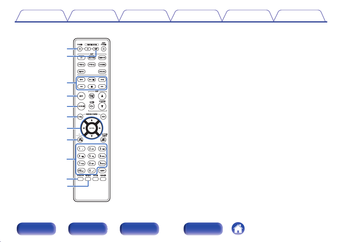
o
CD player operations
A Denon CD player can be operated.
A
Power operation button (POWER X)
B
Remote mode select button (REMOTE MODE CD)
C
System buttons
0
Skip buttons (8 / 9)
0
Play/pause button (1/3)
0
Fast-reverse/Fast-forward buttons (6 / 7)
0
Stop button (n)
D
Information button (INFO)
E
Cursor buttons (uio p)
F
CD PROGRAM button
G
Number buttons (0 – 9, +10)
H
RANDOM button
I
REPEAT button
J
ENTER button
K
CD PURE DIRECT button
L
CLEAR button
M
DIMMER button
N
MODE button
0
The remote control may not operate some products.
Contents Connections Playback Settings Tips Appendix
13
Front panel Rear panel
Remote control
unit
Index
o
Q0
Q1
u
w
e
q
t
y
r
i
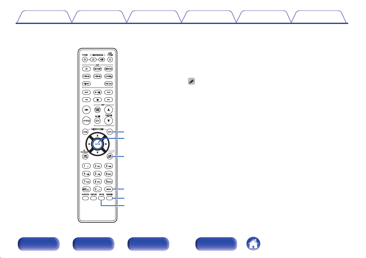
o
Network audio player operations
To operate a Denon network audio player, press the REMOTE MODE
NET button to switch the remote control to the network audio player
operation mode.
A
Power operation button (POWER X)
B
Remote mode select button (REMOTE MODE NET)
C
System buttons
0
Skip buttons (8 / 9)
0
Play/pause button (1/3)
0
Fast-reverse/Fast-forward buttons (6 / 7)
0
Stop button (n)
D
Information button (INFO)
E
SOURCE button
F
NET FAVORITES CALL button
G
Cursor buttons (uio p)
H
NET SRCH button
I
Number buttons (0 – 9, +10)
J
RANDOM button
K
REPEAT button
Contents
Connections Playback Settings Tips Appendix
14
Front panel Rear panel
Remote control
unit
Index
Q2
Q4
Q5
Q6
Q7
Q3
L
NET FAVORITES ADD button
M
ENTER button
N
NET SETUP button
O
CLEAR button
P
DIMMER button
Q
MODE button
0
The amp can be operated with the amp operation buttons even when the remote
control mode is “NET”.
0
When using it, also refer to the operating instructions of the other devices.
0
The remote control may not operate some products.
Contents Connections Playback Settings Tips Appendix
15
Front panel Rear panel
Remote control
unit
Index
o
Contents
Connecting speakers 17
Connecting a playback device 21
Connecting a recording device 22
Connecting to a device with digital audio output connectors 23
Connecting a PC or Mac 24
Connecting the power cord 25
NOTE
0
Do not plug in the power cord until all connections have been completed.
0
Do not bundle power cords together with connection cables. Doing so can result in
humming or noise.
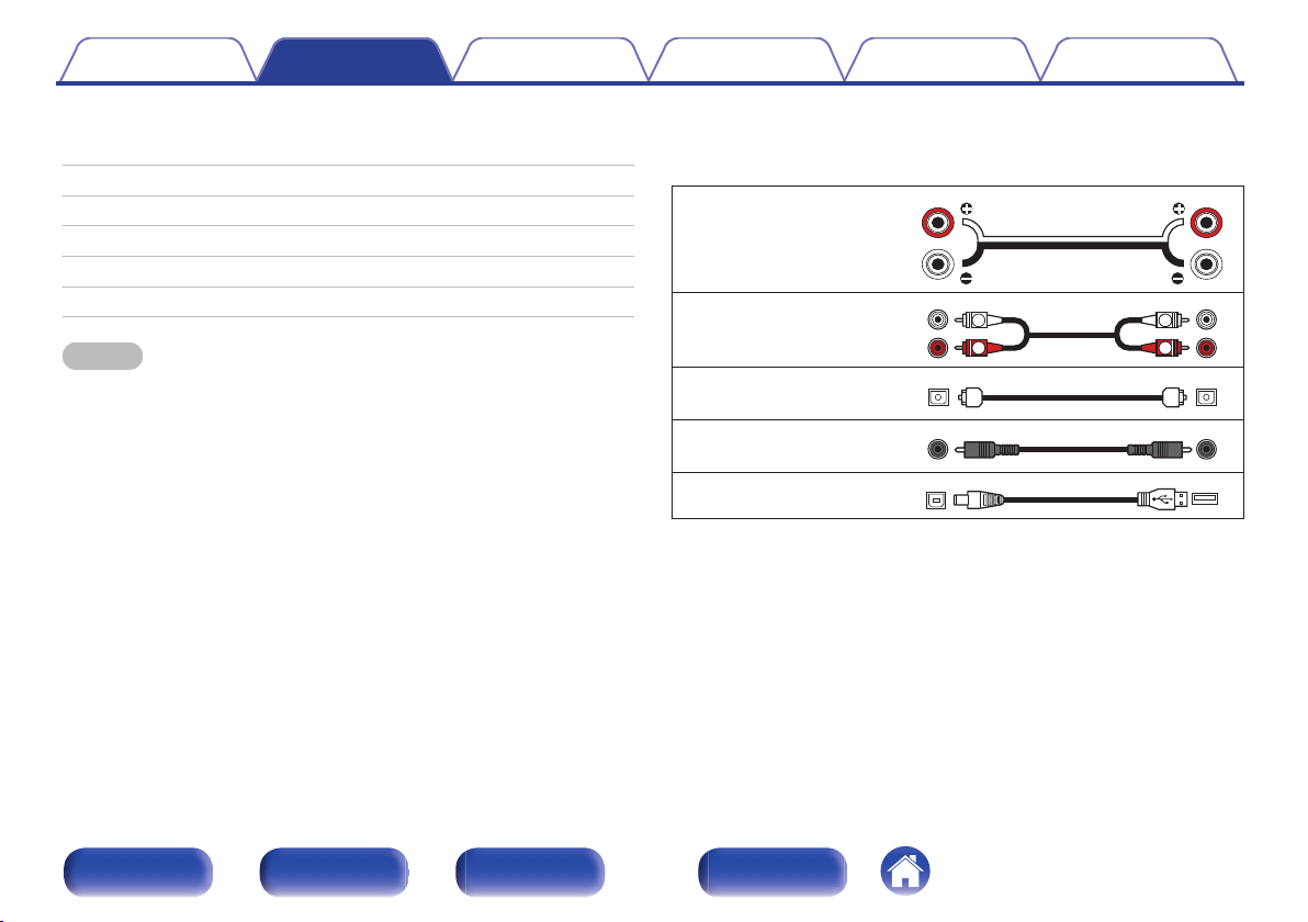
o
Cables used for connections
Provide necessary cables according to the devices you want to
connect.
Speaker cable
.
Audio cable
.
R
L
R
L
Optical cable
.
Coaxial digital cable
.
USB cable
.
Contents Connections Playback Settings Tips Appendix
16
Front panel Rear panel
Remote control
unit
Index
Connecting speakers
NOTE
0
Disconnect this unit’s power plug from the power outlet before connecting the
speakers.
0
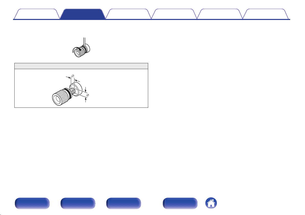
Connect so that the speaker cable core wires do not protrude from the speaker
terminal. The protection circuit may be activated if the core wires touch the rear
panel or if the + and - sides touch each other. (“Protection circuit” (v
p. 52))
0
Never touch the speaker terminals while the power cord is connected. Doing so
could result in electric shock.
0
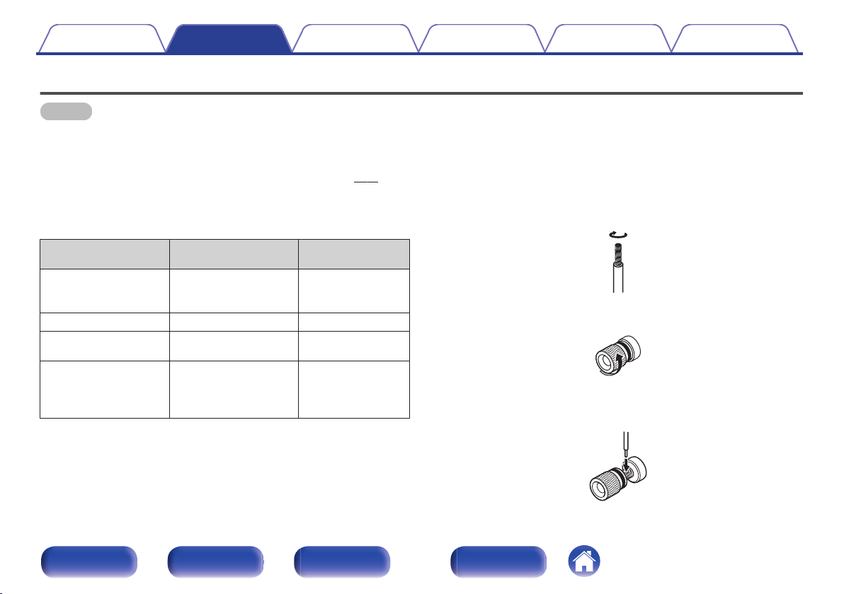
Use speakers with impedances within the ranges shown below to suit how they
are used.
Speaker terminals
used on this unit
No. of connected
speakers
Speaker
Impedance
SPEAKERS A
(Standard
connection)
2 (one set) 4 – 16 Ω/ohms
SPEAKERS B
2 (one set) 4 – 16 Ω/ohms
SPEAKERS A and
SPEAKERS B
4 (two sets) 8 – 16 Ω/ohms
SPEAKERS A and
SPEAKERS B
(Bi-wiring
connection)
2 (one set) 4 – 16 Ω/ohms
o
Connecting the speaker cables
Carefully check the left (L) and right (R) channels and + (red) and – (black)
polarities on the speakers being connected to this unit, and be sure to
connect the channels and polarities correctly.
1
Peel off about 3/8 inch (10 mm) of sheathing from the
tip of the speaker cable, then either twist the core wire
tightly or terminate it.
.
2
Turn the speaker terminal counterclockwise to loosen it.
.
3
Insert the speaker cable’s core wire to all the way into
the speaker terminal.
.
Contents
Connections Playback Settings Tips Appendix
17
Front panel Rear panel
Remote control
unit
Index
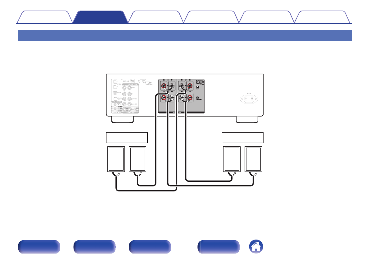
Speaker connection
This unit is equipped with two sets of speaker terminals (SPEAKER A and SPEAKER B). One set of speakers can be connected to each set of terminals,
and a total of two sets of speakers can be connected.
The same signal is output from the SPEAKERS A and SPEAKERS B terminals.
When only one set of speakers is to be connected, use either the SPEAKERS A or SPEAKERS B terminals.
.
wqwq
(R) (L)
wqwq
(R) (L)
SPEAKERS A
SPEAKERS B
Contents
Connections Playback Settings Tips Appendix
19
Front panel Rear panel
Remote control
unit
Index
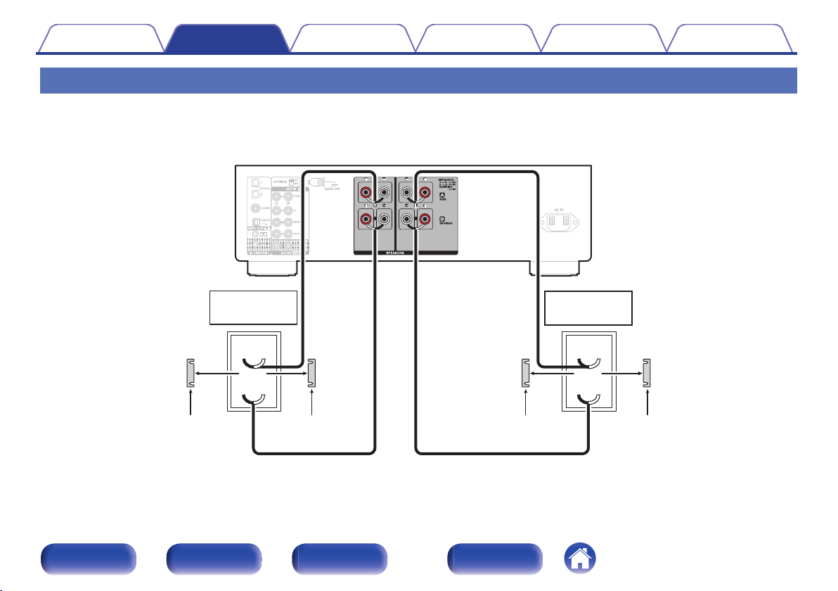
Bi-wiring connection
This connection limits the effects of signal interference between the high range speakers (tweeters) and low range speakers (woofers), allowing you to
enjoy high quality playback.
When bi-wiring with bi-wireable speakers, connect the mid and high range terminals to SPEAKERS A (or SPEAKERS B), the low range terminals to
SPEAKERS B (or SPEAKERS A).
.
wq
wq
HIGH
LOW
wq
wq
HIGH
LOW
Speaker
(R)
Speaker
(L)
Remove shorting bar
Remove shorting bar
Remove shorting barRemove shorting bar
Contents
Connections Playback Settings Tips Appendix
20
Front panel Rear panel
Remote control
unit
Index
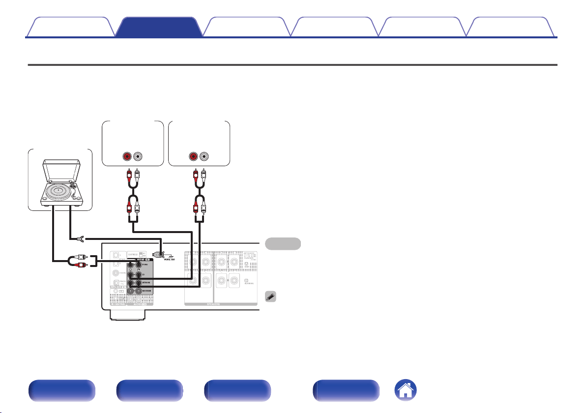
Connecting a playback device
You can connect turntables, CD players and network audio players to this unit.
If you set this unit’s input source to “PHONO” and you accidentally increase the volume without having a turntable connected, you may hear a hum noise
from the speakers.
NOTE
0
The earth terminal (SIGNAL GND) of this unit is not for safety grounding purposes. If this
terminal is connected when there is a lot of noise, the noise can be reduced. Note that
depending on the turntable, connecting the ground line may have the reverse effect of
increasing noise. In this case, it is not necessary to connect the ground line.
0
The PHONO input terminals are equipped with a short pin-plug. Remove this plug to connect a
record player. Store the removed short pin-plug in a safe place so as not to lose it.
GND
AUDIO
OUT
L
R
AUDIO
OUT
LR
AUDIO
OUT
LR
L
L
R
R
L
L
R
R
Network audio
player
CD player
Turntable
Contents Connections Playback Settings Tips Appendix
21
Front panel Rear panel
Remote control
unit
Index
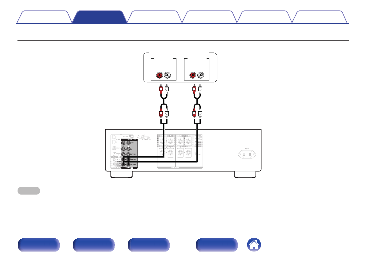
Connecting a recording device
.
LR LR
AUDIO OUT
L
L
R
R
L
L
R
R
AUDIO IN
Recording device
NOTE
0
Never insert the short-circuiting pin plug into the recording output connectors (AUDIO OUT RECORDER). Doing so could result in damage.
Contents Connections Playback Settings Tips Appendix
22
Front panel Rear panel
Remote control
unit
Index
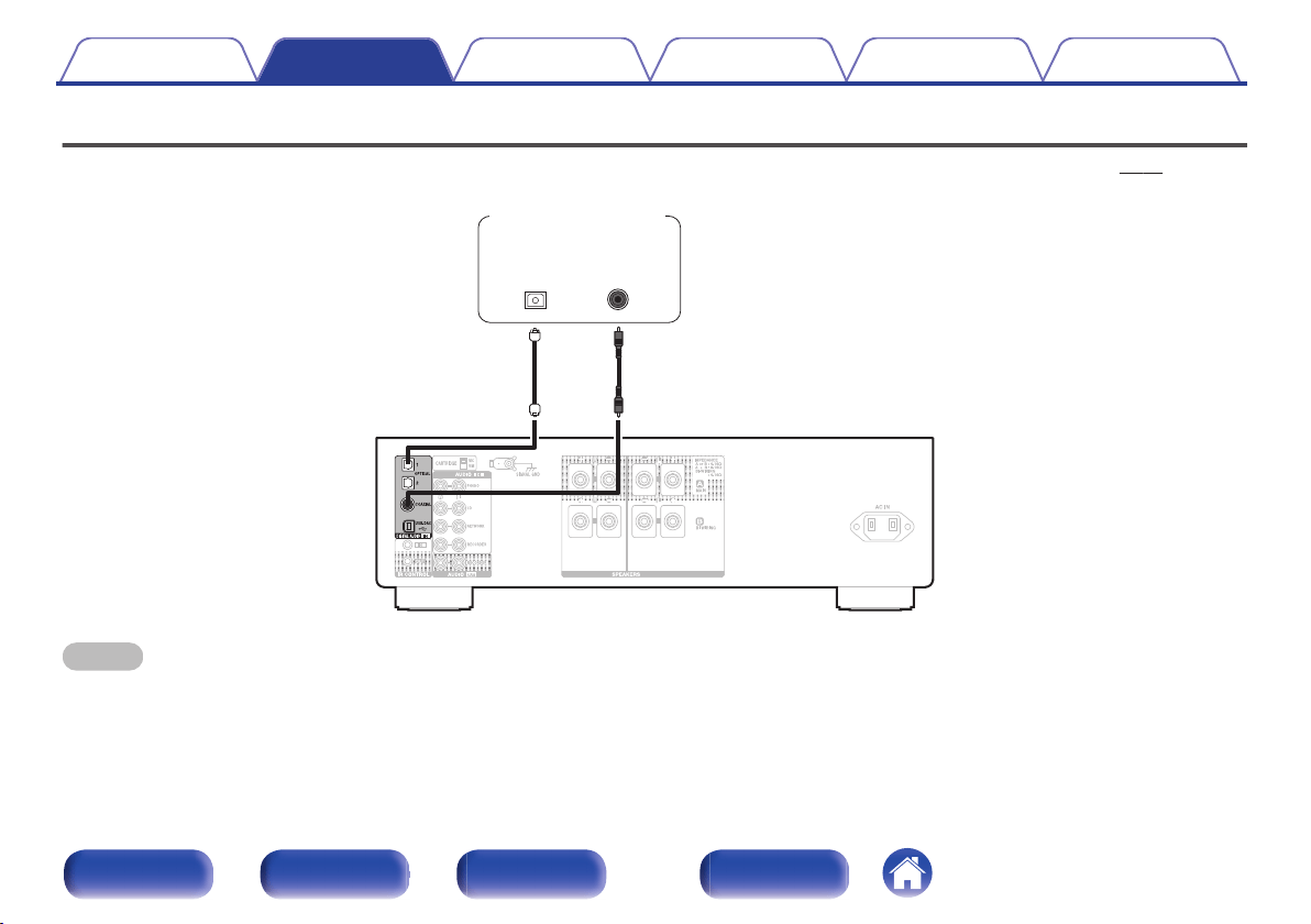
Connecting to a device with digital audio output connectors
Use this connection to input digital audio signals to this unit, and convert the signals for playback using the D/A converter of this unit. (v p. 31)
.
OPTICAL
OUT
COAXIAL
OUT
CD player /
Satellite receiver etc.
NOTE
0
Linear PCM signals with a sampling frequency of 32 kHz, 44.1 kHz, 48 kHz, 88.2 kHz, 96 kHz, 176.4 kHz, or 192 kHz can be input into this device.
0
Do not input non-PCM signals, such as Dolby Digital, DTS and AAC. This causes noise and could damage the speakers.
Contents Connections Playback Settings Tips Appendix
23
Front panel Rear panel
Remote control
unit
Index
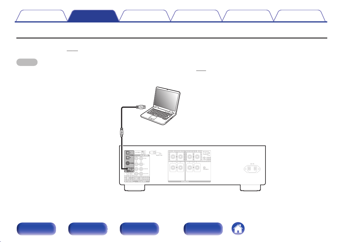
Connecting a PC or Mac
By connecting a computer to the USB-DAC port on the rear panel of this unit using a commercially available USB connecting cable, this unit can be used
as a D/A converter. (v p. 31)
NOTE
0
Before USB connecting this unit to your computer, install the driver software in your computer. (v p. 32)
0
Download the driver software from the PMA-1600NE page of the Denon website.
0
Use a cable that is 10 ft (3 m) or less to connect to the computer.
.
Ty p e A
USB 2.0 cable
(Sold separately)
Ty p e B
Computer on which the driver software and audio
player software are installed
Contents
Connections Playback Settings Tips Appendix
24
Front panel Rear panel
Remote control
unit
Index
o
Contents
Turning the power on 27
Selecting the input source 28
Adjusting the volume 28
Turning off the sound temporarily (Muting) 28
Adjusting the tone 28
Switching the display’s brightness 29
Playing CDs 29
Connecting and playing back from a computer (USB-DAC) 31
Connecting and playing back from a digital device (Coaxial/
Optical) 40
Recording 41
Contents Connections Playback Settings Tips Appendix
26
Front panel Rear panel
Remote control
unit
Index
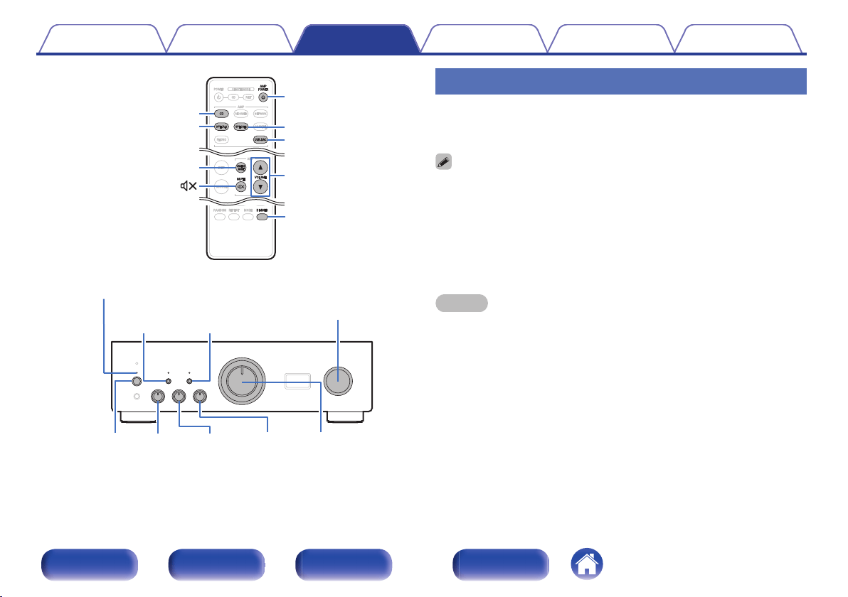
.
ANALOG
MODE
BALANCETREBLE
INPUT SELECTOR
VOLUMEBASS
X
SOURCE
DIRECT
Power indicator
AMP POWER
X
USB-DAC
OPTICAL2
OPTICAL1
MUTE
DIMMER
VOLUME
df
CD
ANALOG MODE
Turning the power on
1
Press X on this unit to turn the power on.
The power indicator lights green.
0
Press AMP POWER X on the remote control unit to turn on power from standby
mode.
o
Switching the power to standby
1
Press AMP POWER X.
The unit switches to standby mode.
NOTE
0
Power continues to be supplied to some of the circuitry even when the power is in
the standby mode. When leaving home for long periods of time or when going on
vacation, either press X on the main unit to turn off the power, or unplug the power
cord from the power outlet.
Contents Connections Playback Settings Tips Appendix
27
Front panel Rear panel
Remote control
unit
Index
Selecting the input source
1
Press the input source select button to be played back.
The selected input source is displayed on the display of this unit.
0
You can also select the input source by turning INPUT SELECTOR on the main
unit.
Adjusting the volume
1
Use VOLUME df to adjust the volume.
0
You can also adjust the volume by turning VOLUME on the main unit.
Turning off the sound temporarily
(Muting)
1
Press MUTE :.
“MUTING” is displayed on the display of this unit.
0
To cancel mute, press MUTE : again.
Adjusting the tone
1
Press SOURCE DIRECT on the main unit to turn off
source direct mode.
The SOURCE DIRECT indicator turns off.
2
Turn the BASS, TREBLE and BALANCE to adjust the
tone.
Contents Connections Playback Settings Tips Appendix
28
Front panel Rear panel
Remote control
unit
Index
Switching the display’s brightness
The brightness of the display can be adjusted to one of four levels.
1
Press DIMMER.
0
The DIMMER button also controls the Denon's Super Audio CD Player
DCD-1600NE, so the DCD-1600NE can be operated simultaneously with this unit.
When the two units have different settings, press and hold in the button for lease 2
seconds to reset them both to the default setting, then make the desired setting.
0
The display brightness is set to most brightly by default.
Playing CDs
This section uses playback from a CD as an example.
1
Press the input source select button (CD) to switch the
input source to “CD”.
“CD” is displayed on the display of this unit.
2
Playback the CD.
3
Use VOLUME df to adjust the volume.
o
Playback in source direct mode
The signal does not pass through the tone adjustment circuitry (BASS,
TREBLE and BALANCE), resulting in playback of a higher sound
quality.
1
Press SOURCE DIRECT on the main unit to turn on
source direct mode.
The SOURCE DIRECT indicator lights.
Contents Connections Playback Settings Tips Appendix
29
Front panel Rear panel
Remote control
unit
Index

o
Playback in ANALOG MODE
When the ANALOG MODE is turned on to playback an analog source
(PHONO, CD, NETWORK, RECORDER), power to the digital input
circuit and the display turn off. This enables you to enjoy high sound
quality audio playback without sound quality being affected by noise
that occurs from the digital control circuit.
1
Press ANALOG MODE to turn analog mode on.
0
The ANALOG MODE indicator lights.
Press ANALOG MODE to toggle between “ANALOG MODE Off”,
“ANALOG MODE 1” and “ANALOG MODE 2”.
ANALOG MODE Off: ANALOG MODE is not used.
ANALOG MODE 1: Turns the digital input circuit power off.
ANALOG MODE 2:
Turns the digital input circuit power and
display off.
0
A digital input source (COAXIAL, OPTICAL 1/2, USB-DAC) cannot be selected
when ANALOG MODE is on.
0
The input source automatically switches to CD if ANALOG MODE is turned on
during playback of a digital input source (COAXIAL, OPTICAL 1/2, USB-DAC).
0
Communication between this unit and the computer is disconnected if ANALOG
MODE is turned on when a computer is connected to the USB-DAC input
connector of this unit. If the unit cannot communicate with the computer after
turning ANALOG MODE off again, disconnect and reconnect the USB cable or
restart the audio player on the computer.
0
When the analog mode is switched, the mute circuit is activated for about 5
seconds.
Contents Connections Playback Settings Tips Appendix
30
Front panel Rear panel
Remote control
unit
Index
Connecting and playing back from a
computer (USB-DAC)
You can enjoy high-quality audio playback from the D/A converter built in
to this unit by inputting music files into this unit from a computer via USB
connection.
0
Before USB connecting this unit to your PC, install the driver software in
your PC.
0
Drivers do not need to be installed for Mac OS.
0
Also, you can use whichever commercially available or downloadable
player software you like to playback files on your computer.
o
Computer (System Requirements)
OS
0
Windows 7, Windows 8, Windows 8.1 or Windows 10
0
Mac OS X 10.10, 10.11 or macOS 10.12
USB
0
USB 2.0: USB High speed/USB Audio Class Ver.2.0
NOTE
0
This unit was checked the operation using the system requirements by us, but
it does not guarantee the operation of all systems.
0
DSD is a registered trademark.
0
Microsoft, Windows 7, Windows 8, Windows 8.1 and Windows
10 are either registered trademarks or trademarks of Microsoft
Corporation in the United States and/or other countries.
0
ASIO is a trademark of Steinberg Media Technologies GmbH.
0
Apple, Macintosh and Mac OS are trademarks of Apple Inc.,
registered in the U.S. and other countries.
Windows
OS
Installing the dedicated driver (v p. 32)
Mac OS
Audio Device Settings (v p. 38)
Contents Connections Playback Settings Tips Appendix
31
Front panel Rear panel
Remote control
unit
Index
o
Installing the dedicated driver
(Windows OS only)
n
Installing the driver software
1
Disconnect the USB cable between your PC and the
unit.
0
The driver software cannot be installed correctly if your PC is
connected to the unit by a USB cable.
0
If the unit and your PC are connected by a USB cable and the PC
is switched on before installation, disconnect the USB and restart
the PC.
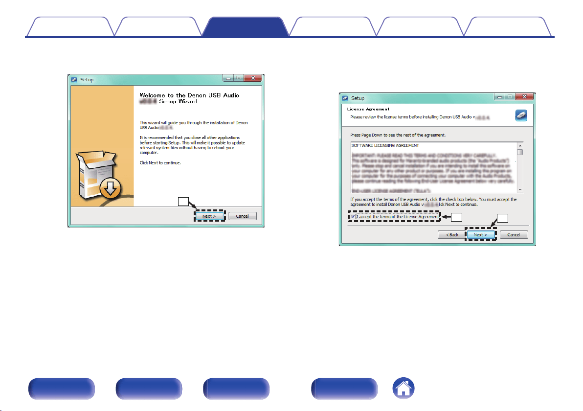
2
Download the dedicated driver from the “Download”
section of the PMA-1600NE page of the Denon website
onto your PC.
3
Unzip the downloaded file, and double-click the exe
file.
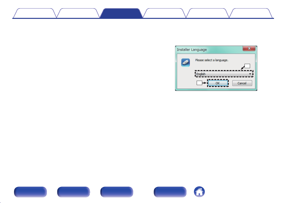
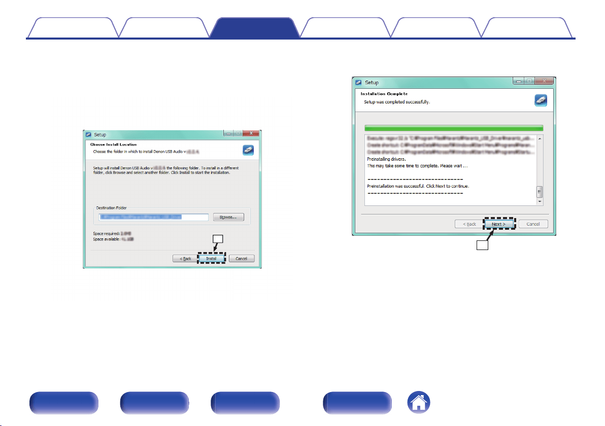
4
Install the driver.
A
Select the language to use for the installation.
B
Click “OK”.
.
q
w
Contents Connections Playback Settings Tips Appendix
32
Front panel Rear panel
Remote control
unit
Index
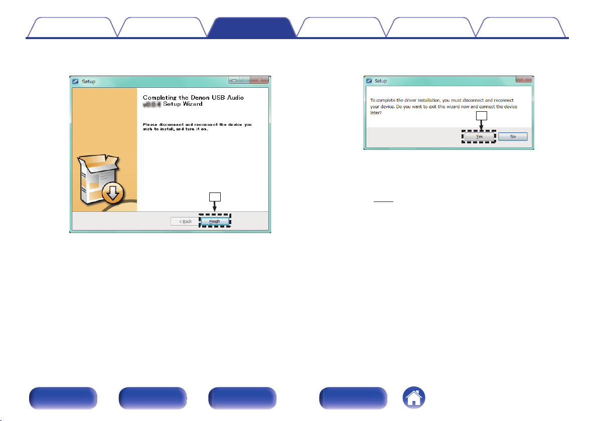
H
When the installation is completed, click “Finish”.
.
i
I
Click “Yes”.
.
o
5
With the unit power off, connect the unit and PC using
a USB cable (sold separately).
0
For details on connections, see “Connecting a PC or
Mac” (v p. 24).
Contents
Connections Playback Settings Tips Appendix
35
Front panel Rear panel
Remote control
unit
Index
6
Press X on this unit.
0
When the unit power is turned on, the PC automatically finds and
connects to the unit.
7
Press the input source select button (USB-DAC) to
switch the input source to “USB-DAC”.
8
Checking the installed driver.
A
Click the “Start” button and click “Control Panel” on the PC.
0
The control panel setting list is displayed.
B
Click the “Sound” icon.
0
The sound menu window is displayed.
C
Check that there is a checkmark next to “Default Device” under in
“PMA-1600NE” of the “Playback” tab.
0
When there is a checkmark for a different device, click
“PMA-1600NE” and “Set Default”.
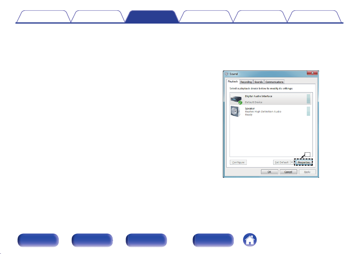
9
Checking audio output.
Outputs a TEST signal from the PC and checks the audio output
from the USB-DAC function.
A
Select “PMA-1600NE” and click “Properties”.
0
The PMA-1600NE Properties window is displayed.
.
PMA-1600NE
q
Contents
Connections Playback Settings Tips Appendix
36
Front panel Rear panel
Remote control
unit
Index
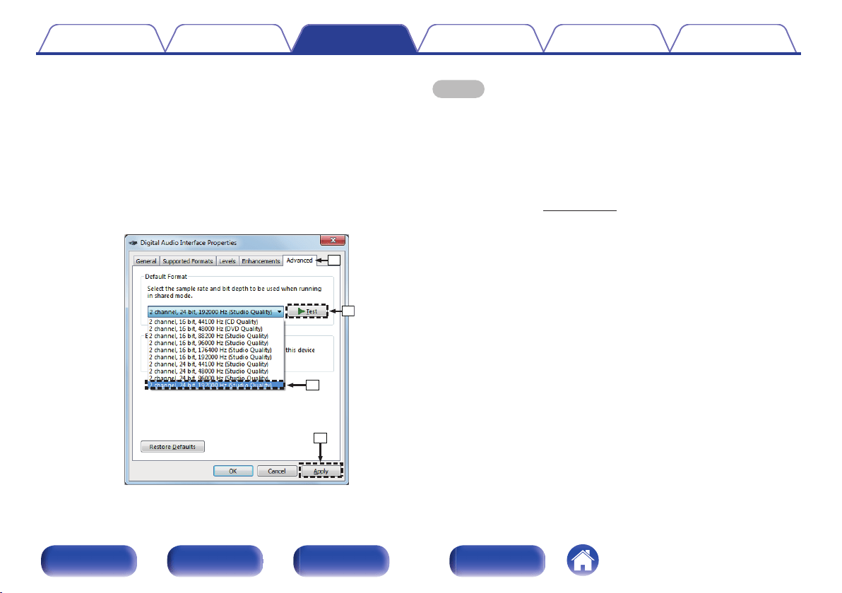
B
Click the “Advanced” tab.
C
Select the sampling rate and bit rate to be applied to the D/A
converter.
0
It is recommended that “2 channel, 24 bit, 192000 Hz (Studio
Quality)” is selected (Windows 7).
0
It is recommended that “2 channel, 32 bit, 192000 Hz (Studio
Quality)” is selected (Windows 8/Windows 8.1/Windows 10).
D
Click “Apply”.
E
Click “Test”.
0
Check that audio from this unit is output from the PC.
.
w
e
r
t
NOTE
0
The dedicated driver must be installed in the PC before this unit is connected to a
PC. Operation will not occur correctly if connected to the PC before the dedicated
driver has been installed.
0
Operation may fail in some PC hardware and software configurations.
0
Player software supporting the Audio Stream Input Output (ASIO) driver is
required to play files with a sampling frequency of 352.8 kHz/384 kHz without
downsampling. Check your player software before playing files with the ASIO
driver.
0
Please see the FAQ at
www.denon.com if you experience any issues getting audio
to play from your PC through the this unit. You may also want to check the support
pages for your audio player application.
Contents Connections Playback Settings Tips Appendix
37
Front panel Rear panel
Remote control
unit
Index
o
Audio Device Settings (Mac OS only)
A
With the unit power off, connect the unit and Mac using a USB cable
(sold separately).
0
For the connection procedure, refer to the “Connecting a PC or Mac”
section. (v p. 24)
B
Press X.
C
Press USB-DAC to switch the input source to “USB-DAC”.
D
Move the cursor to “Go” on the computer screen, and then click
“Utilities”.
0
The utility list is displayed.
E
Double-click “Audio MIDI Setup”.
0
The “Audio Devices” window is displayed.
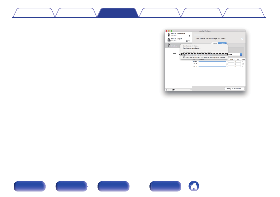
F
Check that “Use this device for sound output” is checked in
“PMA-1600NE”.
0
If a different device is checked, select and “Secondary click” on
“PMA-1600NE”, and then select “Use this device for sound output”.
.
y
PMA-1600NE
PMA-1600NE
Contents
Connections Playback Settings Tips Appendix
38
Front panel Rear panel
Remote control
unit
Index
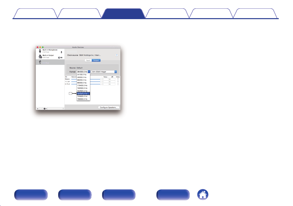
G
Select the “PMA-1600NE” format.
0
It is normally recommended to set the format to “384000.0 Hz” and
“2ch-32 bit Interger”.
.
u
PMA-1600NE
PMA-1600NE
H
Quit Audio MIDI Setup.
o
Playback
Install the desired player software on your computer beforehand.
Use the rear panel USB-DAC port to connect this unit to a computer.
1
Press the input source select button (USB-DAC) to
switch the input source to “USB-DAC”.
“USB-DAC” is displayed on the display of this unit.
Start playback on the computer’s player software.
The digital audio signal that is being input is shown as follows in the
display.
“USB: PCM
or
“USB: DSD
xxxxkHz” xxxMHz”
(xxxx is the sampling frequency.)
0
If the sampling frequency cannot be detected, “Unlocked” will be
displayed.
0
“Unsupported” is displayed when audio signals that are not
supported by this unit are input.
Contents
Connections Playback Settings Tips Appendix
39
Front panel Rear panel
Remote control
unit
Index
o
Audio signals that can be played back
See “D/A converter” (v p. 51).
NOTE
0
Perform operations such as playback and pause on the computer. At this time, you
cannot perform operations with buttons on this unit or the remote control.
0
When this unit is functioning as a D/A converter, sound is not output from the
computer’s speakers.
0
If the computer is disconnected from this unit while the computer music playback
software is running, the playback software may freeze. Always exit the playback
software before disconnecting the computer.
0
When an error occurs on the computer, disconnect the USB cable and restart the
computer.
0
The sampling frequency of the music playback software and sampling frequency
displayed on this unit may differ.
0
Use a cable that is 10 ft (3 m) or less to connect to the computer.
Connecting and playing back from a
digital device (Coaxial/Optical)
1
Connect digital device to this unit. (v p. 23)
2
Press the input source select button (COAXIAL or
OPTICAL 1/2) to switch the input source to “COAXIAL”
or “OPTICAL 1/2”.
The digital audio signal that is being input is shown as follows in the
display.
“COAX:PCM
or
“OPT1:PCM
or
“OPT2:PCM
xxxxkHz” xxxxkHz” xxxxkHz”
(xxxx is the sampling frequency.)
0
If the sampling frequency cannot be detected, “Unlocked” will be
displayed.
0
“Unsupported” is displayed when audio signals that are not
supported by this unit are input.
Contents
Connections Playback Settings Tips Appendix
40
Front panel Rear panel
Remote control
unit
Index
o
Audio signals that can be played back
See “D/A converter” (v p. 51).
NOTE
0
Do not input non-PCM signals, such as Dolby Digital, DTS and AAC. This causes
noise and could damage the speakers.
Recording
Audio signals input into this unit can be output to an external recording
device. When recording audio from a playback device connected to this
unit, audio can be recorded with the playback device still connected to this
unit.
1
Press X on this unit to turn the power on.
2
Press the input source select button to switch to the
input source from which you want to record.
The selected input source is displayed on the display of this unit.
3
Recording starts.
0
For information on operations, see the owner’s manual of the
recording device.
Contents Connections Playback Settings Tips Appendix
41
Front panel Rear panel
Remote control
unit
Index
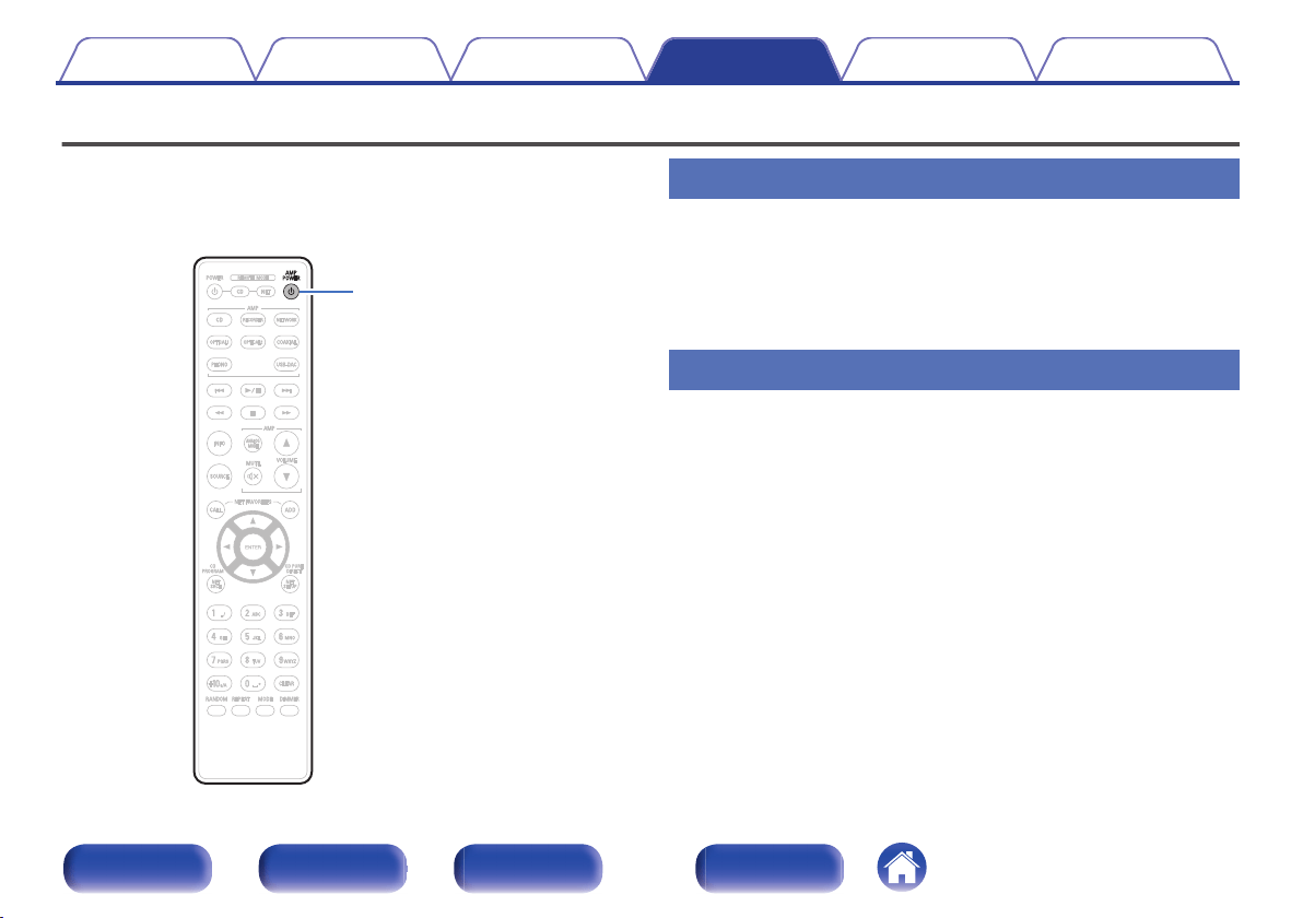
Setting the Auto Standby mode
You can set the unit to automatically switch to standby mode if the unit is
not operated for 30 minutes when there is no audio input (Auto Standby
mode).
Auto Standby mode is set to off by default.
.
AMP POWER
X
Turning Auto Standby mode on
1
Press and hold AMP POWER X on the remote control
unit for more than 5 seconds to turn the Auto Standby
mode on.
“AutoStby On” is displayed on the display of this unit.
Turning Auto Standby mode off
1
Press and hold AMP POWER X on the remote control
unit for more than 5 seconds to turn the Auto Standby
mode off.
“AutoStby Off” is displayed on the display of this unit.
Contents Connections Playback Settings Tips Appendix
42
Front panel Rear panel
Remote control
unit
Index
o
Contents
Tips
I want to adjust the tone myself 44
I want sound playback that is faithful to the original sound 44
I want to enjoy higher sound quality from the analog input source 44
I want to use bi-wiring compatible speakers 44
Troubleshooting
Power does not turn on / Power is turned off 46
Operations cannot be performed through the remote control unit 47
No sound comes out 48
Desired sound does not come out 48
Sound is interrupted or noise occurs 49
PC or Mac files cannot be played back 50
Audio from digital devices cannot be played back (Coaxial/Optical) 50
Contents Connections Playback Settings Tips Appendix
43
Front panel Rear panel
Remote control
unit
Index

Tips
I want to adjust the tone myself
0
Use the BASS, TREBLE and BALANCE knobs to adjust the sound as desired. (v p. 28)
I want sound playback that is faithful to the original sound
0
Set the Source Direct mode on. (v p. 29)
I want to enjoy higher sound quality from the analog input source
0
Set the Analog mode on. (v p. 30)
I want to use bi-wiring compatible speakers
0
This unit is compatible with bi-wiring connections. Enjoy high quality playback by using bi-wiring connections. (v
p. 20)
Contents Connections Playback Settings Tips Appendix
44
Front panel Rear panel
Remote control
unit
Index
Troubleshooting
If a problem should arise, first check the following:
1. Are the connections correct?
2. Is the set being operated as described in the owner’s manual?
3. Are the other devices operating properly?
If this unit does not operate properly, check the corresponding symptoms in this section.
If the symptoms do not match any of those described here, consult your dealer as it could be due to a fault in this unit. In this case, disconnect the power
immediately and contact the store where you purchased this unit.
Contents Connections Playback Settings Tips Appendix
45
Front panel Rear panel
Remote control
unit
Index
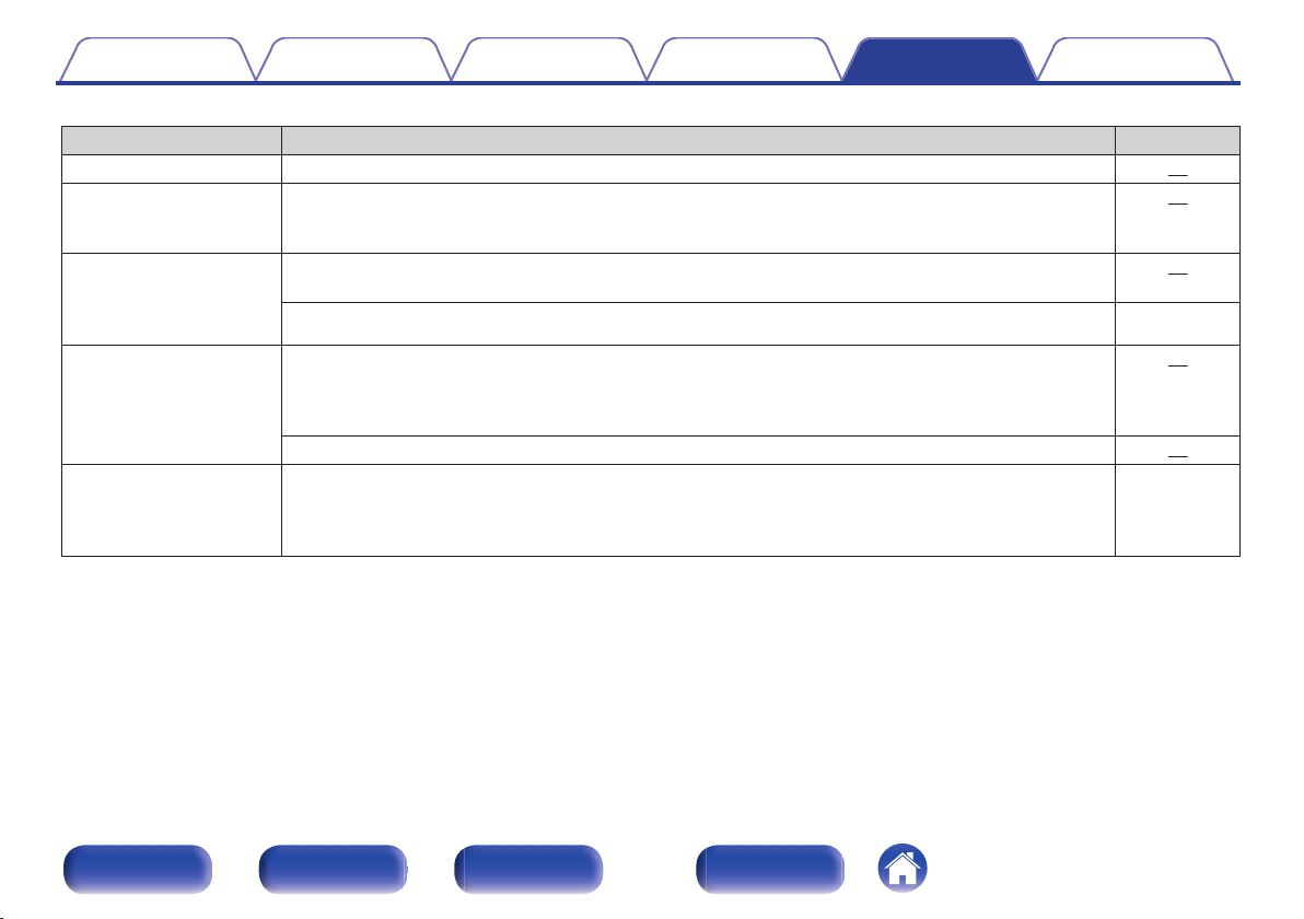
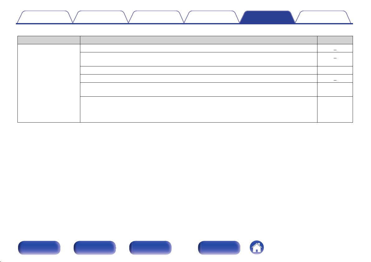
o
Power does not turn on / Power is turned off
Symptom Cause / Solution Page
Power is not turned on.
0
Check whether the power plug is correctly inserted into the power outlet. 25
Power automatically turns
off.
0
The Auto Standby mode is set. The Auto Standby mode switches the unit to standby mode when the unit
is not operated for approximately 30 minutes. To disable the Auto Standby mode, press and hold the
AMP POWER X button for more than 5 seconds when the Auto Standby mode is enabled.
42
Power turns off and the
power indicator flashes in
red approx. every 0.5
seconds.
0
The protection circuit has been activated due to a rise in temperature within this unit. Turn the power off,
wait about an hour until this unit cools down sufficiently, and then turn the power on again.
52
0
Please re-install this unit in a place having good ventilation. -
Power turns off and the
power indicator flashes in
red approx. every 0.25
seconds.
0
Check the speaker connections. The protection circuit may have been activated because speaker cable
core wires came in contact with each other or a core wire was disconnected from the connector and
came in contact with the rear panel of this unit. After unplugging the power cord, take corrective action
such as firmly re-twisting the core wire or taking care of the connector, and then reconnect the wire.
17
0
Turn down the volume and turn on the power again. 27
When the power is turned
on, the power indicator
flashes red approx. every
0.25 seconds.
0
This unit’s amplifier circuit has failed. Turn off the power and please contact the Denon service adviser. -
Contents Connections Playback Settings Tips Appendix
46
Front panel Rear panel
Remote control
unit
Index
o
Operations cannot be performed through the remote control unit
Symptom Cause / Solution Page
Operations cannot be
performed through the
remote control unit.
0
Batteries are worn out. Replace with new batteries. 5
0
Operate the remote control unit within a distance of about 23 ft/7 m from this unit and at an angle of within
30°.
5
0
Remove any obstacle between this unit and the remote control unit. -
0
Insert the batteries in the proper direction, checking the q and w marks.
5
0
The set’s remote control sensor is exposed to strong light (direct sunlight, inverter type fluorescent bulb
light, etc.). Move the set to a place in which the remote control sensor will not be exposed to strong light.
-
0
When using a 3D video device, the remote control unit of this unit may not function due to effects of
infrared communications between units (such as TV and glasses for 3D viewing). In this case, adjust the
direction of units with the 3D communications function and their distance to ensure they do not affect
operations from the remote control unit of this unit.
-
Contents Connections Playback Settings Tips Appendix
47
Front panel Rear panel
Remote control
unit
Index

o
No sound comes out
Symptom Cause / Solution Page
No sound comes out of
speakers.
0
Check the connections for all devices. 16
0
Insert connection cables all the way in. -
0
Check that input connectors and output connectors are not reversely connected. -
0
Check cables for damage. -
0
Check that speaker cables are properly connected. Check that cable core wires come in contact with the
metal part on speaker terminals.
17
0
Securely tighten the speaker terminals. Check speaker terminals for looseness. 17
0
Check that the proper input source is selected. 28
0
The volume is set to the minimum level. Adjust the volume to a suitable level. 28
0
Cancel the muting mode. 28
0
No sound is output from the speakers when headphones are connected. 9
o
Desired sound does not come out
Symptom Cause / Solution Page
No sound comes out of a
specific speaker.
0
Check that speaker cables are properly connected. 17
0
Adjust the BALANCE control knob. 28
The left and right of stereo
sound is reversed.
0
Check whether the left and right speakers are connected to the correct speaker terminals. 17
Contents Connections Playback Settings Tips Appendix
48
Front panel Rear panel
Remote control
unit
Index

o
Sound is interrupted or noise occurs
Symptom Cause / Solution Page
When playing a record, the
sound is distorted.
0
Adjust to a proper needle pressure. -
0
Check the tip of the needle. -
0
Replace the cartridge. -
When playing a record, a
humming noise comes out
of the speakers.
0
Check that the turntable is connected correctly. 21
0
If there is a TV or AV device near the turntable, such devices may affect the playback sound. Install the
turntable in a location as far away as possible from the TV or other AV devices.
-
When playing a record, a
humming noise comes out
of the speakers when the
volume is high. (Howling
phenomenon)
0
Install the turntable and speakers as far from each other as possible. 21
0
The vibrations from the speakers are being transmitted to the player through the floor. Use cushions, etc.,
to absorb the speakers’ vibrations.
-
Sound is interrupted during
playback of tracks saved
on a computer.
0
Do not start applications other than the player software while playing music on your computer. -
Contents Connections Playback Settings Tips Appendix
49
Front panel Rear panel
Remote control
unit
Index

o
PC or Mac files cannot be played back
Symptom Cause / Solution Page
This unit is not recognized
on the computer.
0
Reconnect the USB cable to the USB port on your computer. When this unit is still not recognized after
reconnection, connect to a different USB port.
24
0
Restart your computer. -
0
Check the OS of your computer. 31
0
When your computer is running on Windows, a dedicated driver software should be installed. 32
This unit is not selected as
the playback device.
0
Select this unit as the playback device in the sound settings on the computer. 31
“Unlocked” is displayed.
0
When digital audio signals cannot be detected properly, “Unlocked” is displayed. 39
“Unsupported” is
displayed.
0
“Unsupported” is displayed when audio signals that are not supported by this unit are input. Check the
settings on your computer or player software.
39
0
If the computer you use is “Mac OS”, please check if the “PMA-1600NE” format is set below “384000.0
Hz” using the “Audio MIDI Setup”.
38
o
Audio from digital devices cannot be played back (Coaxial/Optical)
Symptom Cause / Solution Page
“Unlocked” is displayed.
0
When digital audio signals cannot be detected properly, “Unlocked” is displayed. 40
“Unsupported” is
displayed.
0
“Unsupported” is displayed when audio signals that are not supported by this unit are input. Check the
audio output signal format from your digital device.
40
Contents Connections Playback Settings Tips Appendix
50
Front panel Rear panel
Remote control
unit
Index
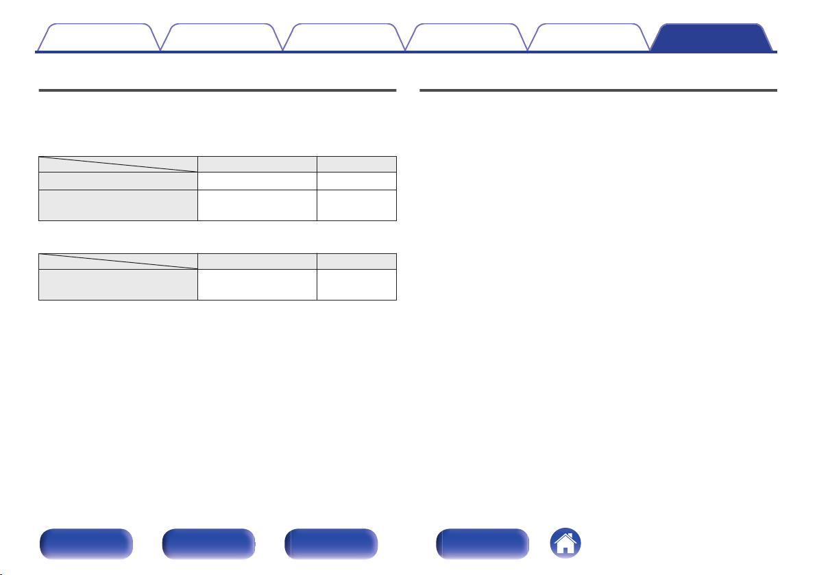
D/A converter
o
Specifications of supported audio signals
n
USB-DAC
Sampling frequency Bit length
DSD (2-channel) 2.8/5.6/11.2 MHz 1 bit
Linear PCM (2-channel)
44.1/48/88.2/96/176.4/
192/352.8/384 kHz
16/24/32 bits
n
Coaxial/Optical
Sampling frequency Bit length
Linear PCM (2-channel)
32/44.1/48/88.2/96/
176.4/192 kHz
16/24 bits
Explanation of terms
DSD (Direct-Stream Digital)
One of the audio data recording methods, it is the signal aspect used to
store audio signals on a super audio CD, and is Δ-Σ modulated digital
audio.
Sampling frequency
Sampling involves taking a reading of a sound wave (analog signal) at
regular intervals and expressing the height of the wave at each reading in
digitized format (producing a digital signal).
The number of readings taken in one second is called the “sampling
frequency”. The larger the value, the closer the reproduced sound is to the
original.
Linear PCM
This is an uncompressed PCM (Pulse Code Modulation) signal. This is the
same system used for CD audio but uses 192 kHz, 96 kHz, and 48 kHz
sampling frequencies on Blu-ray Disc or DVD and provides higher
resolution than CD.
Contents
Connections Playback Settings Tips Appendix
51
Front panel Rear panel
Remote control
unit
Index
Speaker impedance
This is an AC resistance value, indicated in Ω (ohms).
Greater power can be obtained when this value is smaller.
Source direct
Playback with higher fidelity to the source becomes possible, as input
audio signals are output by bypassing the audio quality-control circuits
(BASS/TREBLE/BALANCE).
Protection circuit
This is a function to prevent damage to devices within the power supply
when an abnormality such as an overload, excess voltage occurs or over
temperature for any reason.
Trademark information
.
Adobe, the Adobe logo and Reader are either registered trademarks or
trademarks of Adobe Systems Incorporated in the United States and/or
other countries.
Contents Connections Playback Settings Tips Appendix
52
Front panel Rear panel
Remote control
unit
Index
Specifications
o
Power amplifier section
Rated Output Power: 2-channel driving (CD → SP OUT)
70 W + 70 W (8 Ω/ohms, 20 Hz - 20 kHz, T.H.D. 0.07 %)
140 W + 140 W (4 Ω/ohms, 1 kHz, T.H.D. 0.7 %)
Total harmonic distortion: 0.01 % (Rated output: –3 dB), 8 Ω/ohms, 1 kHz
Output terminals: Speaker A or B: 4 – 16 Ω/ohms
Speaker A + B: 8 – 16 Ω/ohms
Suited for headphones/stereo headphones
o
Pre amplifier section
Input Sensitivity/Input Impedance: PHONO (MM): 2.5 mV / 47 kΩ/kohms
PHONO (MC): 200 μV / 100 Ω/ohms
CD, NETWORK, RECORDER:
125 mV / 47 kΩ/kohms (SOURCE DIRECT: Off)
125 mV / 23 kΩ/kohms (SOURCE DIRECT: On)
RIAA Deviation: PHONO: 20 Hz – 20 kHz ±0.5 dB
Maximum Input: PHONO (MM): 130 mV / 1 kHz
PHONO (MC): 10 mV / 1 kHz
Contents Connections Playback Settings Tips Appendix
53
Front panel Rear panel
Remote control
unit
Index
o
Overall performance
SN Ratio (A network): PHONO (MM): 89 dB
(With input terminals short-circuited, 5 mV input signal)
PHONO (MC): 74 dB
(With input terminals short-circuited, 0.5 mV input signal)
CD, NETWORK, RECORDER: 108 dB (input terminals short-circuited)
Frequency response: 5 Hz – 100 kHz (0 – -3 dB)
Tone control: BASS: 100 Hz ±8 dB
TREBLE: 10 kHz ±8 dB
0
Digital input signal format
Format: Digital audio interface (Linear PCM)
Coaxial input: 0.5 Vp-p / 75 Ω/ohms
Optical input: More than – 27 dBm
Optical wavelength: 660 nm
o
General
Power supply: AC 120 V, 60 Hz
Power consumption: 295 W
Power consumption in standby mode: 0.2 W
For the purpose of improvement, the specifications and design are subject to change without notice.
Contents
Connections Playback Settings Tips Appendix
54
Front panel Rear panel
Remote control
unit
Index
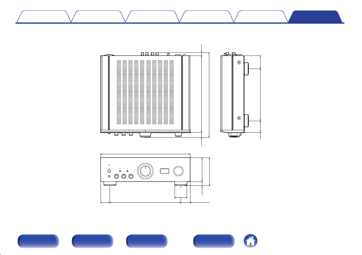
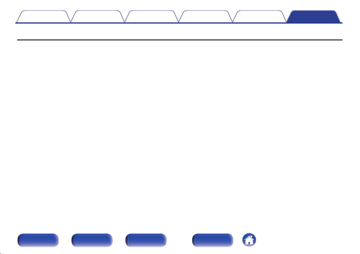
o
Dimensions (Unit : in. (mm))
.
10 (252)
2 3/8
(58)
2 5/8
(64)
3/4
(18)
4 5/8 (117)
5 3/8 (135)
17 1/8 (434)
13 5/8 (344)
1 7/8 (45)
1 7/8
(45)
14 3/4 (374)
16 1/4 (410)
7/8
(21)
5/8
(15)
2 3/8
(60)
o
Weight : 38 lb 13 oz (17.6 kg)
Contents Connections Playback Settings Tips Appendix
55
Front panel Rear panel
Remote control
unit
Index
Index
v A
Auto Standby mode ........................................ 42
v B
BALANCE ...................................................... 28
BASS ............................................................. 28
Bi-wiring ......................................................... 20
v C
CD player ................................................. 21, 23
v D
D/A Converter ................................................ 31
v I
Input source ................................................... 28
Install the driver .............................................. 32
v M
Muting ............................................................ 28
v N
Network audio player ..................................... 21
v P
PC .................................................................. 24
Protection circuit ............................................ 52
v R
Recording device ........................................... 22
Remote control unit ........................................ 12
v S
Satellite receiver ............................................. 23
Source direct ............................................ 29, 52
Speaker impedance ....................................... 52
Speakers ........................................................ 17
v T
Tips ................................................................ 44
Tone ............................................................... 28
TREBLE ......................................................... 28
Troubleshooting ............................................. 45
Turntable ........................................................ 21
v U
USB-DAC ....................................................... 31
v V
Volume ........................................................... 28
Contents
Connections Playback Settings Tips Appendix
56
Front panel Rear panel
Remote control
unit
Index

.
www.denon.com
3520 10605 00AD
Copyright © 2016 D&M Holdings Inc. All Rights Reserved.
57