
ENGLISH
www.lg.com
Copyright © 2019 LG Electronics Inc. All Rights Reserved.
OWNER’S MANUAL
AIR
CONDITIONER
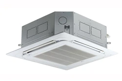
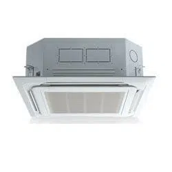
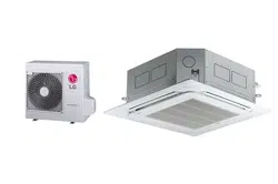
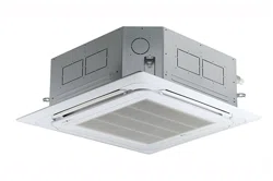
CEILING CASSETTE, CEILING CONCEALED DUCT
Original instruction
MFL67870342
Rev.00_011119
Please read this manual carefully before operating your set and retain it for future
reference.
2
IMPORTANT SAFETY INSTRUCTIONS
ENGLISH
IMPORTANT SAFETY INSTRUCTIONS
The following symbols are displayed on indoor and outdoor units.
READ ALL INSTRUCTIONS BEFORE USING THE APPLIANCE.
Always comply with the following precautions to avoid dangerous situations and ensure peak
performance of your product
WARNING
It can result in serious injury or death when the directions are ignored
CAUTION
It can result in minor injury or product damage when the directions are ignored. This appliance is
intended to be used by expert or trained users in shops, in light industry and on farms, or for
commercial use by lay persons.
WARNING
• Always ground the product.
- There is a risk of electric shock.
• Do not use a defective or underrated circuit breaker. Use the correctly rated breaker and fuse.
- There is risk of fire or electric shock.
• Do not use a multi consent.
- Always use this appliance on a dedicated cicuit and breaker. Otherwise it can cause electric
shock or fire.
• For electrical work, contact the dealer, seller, a qualified electrician, or an Authorized Service
Center.
- Do not disassemble or repair the product by yourself. There is risk of fire or electric shock.
• Always ground the product as per the wiring diagram.
- Do not connect the ground wire to gas or water pipes lightening rod or telephone ground wire.
There is risk of fire or electric shock.
• Install the panel and the cover of control box securely.
- There is risk of fire or electric shock due to dust, water etc.
• Use the correctly rated breaker or fuse.
- There is risk of fire or electric shock.
!
!
!
Read the precautions in this manual
carefully before operating the unit.
This appliance is filled with
flammable refrigerant (R32)
This symbol indicates that the
Operation Manual should be read
carefully.
This symbol indicates that a service
personnel should be handling this
equipment with reference to the
Installation Manual.

IMPORTANT SAFETY INSTRUCTIONS
3
ENGLISH
• Do not modify or extend the power cable.
- If the power cable or cord has scrathes or skin peeled off or deteriorated then it must be
replaced. There is risk of fire or electric shock.
• For installation, removal or reinstall, always contact the dealer or an Authorized Service Center.
- There is risk of fire, electric shock, explosion, or injury.
• Do not install the product on a defective installation stand.
- Be sure that the installation area does not deteriorate with age. It may cause product to fall.
• Never install the outdoor unit on a moving base or a place from where it can fall down.
- The falling outdoor unit can cause damage or injury or even death of a person.
• When the product is soaked (flooded or submerged) in water, contact an Authorized Service
Center for repair before using it again.
- There is risk of fire or eletric shock.
• Be sure to check the refrigerant to the used.
- Please read the label on the product. Incorrect refrigerant used can prevent the normal
operation of the unit.
• Don't use a power cord, a plug or a loose socket which is damaged.
- Otherwise it may cause a fire or electrical shock.
• Do not touch, operate, or repair the product with wet hands.
- Hold the plug by hand when taking out. There is risk of electric shock or fire.
• Do not place a heater or other heating appliances near the power cable.
- There is risk of fire and electric shock.
• Do not allow water to run into electric parts. Install the unit away from water sources.
- There is risk of fire, failure of the product, or electric shock.
• Do not store or use or even allow flammable gas or combustibles near the product.
- There is risk of fire.
• Indoor/outdoor wiring connections must be secured tightly and the cable should be routed
properly so that there is no force pulling the cable from the connection terminals.
- Improper or loose connections can cause heat generation or fire.
• Safely dispose off the packing materials.
- Like screws, nails, batteries, broken things etc after installation or svc and then tear away and
thraw away the plastic packaging bags. Children may play with them and cause injury.
• Make sure to check that the power cable plug is not dirty, loose or broken and then only insert
the plug completely.
- Dirty, loose or broken power plug can cause electric shock or fire.
• In outdoor unit the step-up capacitor supplies high voltage electricity to the electrical
components.
- Be sure to discharge the capacitor completely before conducting the repair work.
An charged capacitor can cause electrical shock.
• When installing the unit, use the installation kit provided with the product.
- Otherwise the unit may fall and cause severe injury.

4
IMPORTANT SAFETY INSTRUCTIONS
ENGLISH
• Be sure to use only those parts which are listed in the svc parts list.
- Never attempt to modify the equipment. The use of inappropriate parts can cause an electrical
shock, excessive heat generation or fire.
• Do not use the product in a tightly closed space for a long time. Perform ventilation regularly.
- Oxygen deficiency could occur and hence harm your health.
• Do not open the front grille of the product during operation. (Do not touch the electrostatic
filter, if the unit is so equipped.)
- There is risk of physical injury, electric shock, or product failure.
• If strange sounds, smell or smoke comes from product.
- Immediately turn the breaker off or disconnect the power supply cable. There is risk of electric
shock or fire.
• Ventilate the product room from time to time when operating it together with a stove, or
heating element etc.
- Oxygen deficiency can occur and hence harm your health.
• Turn the main power off and unplug the unit when cleaning or repairing the product.
- There is risk of electric shock.
• When the product is not to be used for a long time, disconnect the power supply plug or turn
off the breaker.
- There is risk of product damage or failure, or unintended operation.
• Take care to ensure that nobody especially kids could step on or fall onto the outdoor unit.
- This could result in personal injury and product damage.
• Take care to ensure that power cable could not be pulled out or damaged during operation.
- There is risk of fire or electric shock.
• Do not place ANYTHING on the power cable.
- There is risk of fire or electric shock.
• Do not plug or unplug the power supply plug to turn the unit ON/OFF.
- There is risk of fire or electric shock.
• When flammable gas leaks, turn off the gas and open a window for ventilation before turn the
product on.
- Do not use the telephone or turn switches on or off. There is risk of explosion or fire.
• Do not turn on the breaker or power under condition that front panel, cabinet, top cover, control
box cover are removed or opened.
- Otherwise, it may cause fire, electric shock, explosion or death.
• Use a vacuum pump or Inert (nitrogen) gas when doing leakage test or air purge.
- Do not compress air or Oxygen and Do not use Flammable gases.
Otherwise, it may cause fire or explosion. There is the risk of death, injury, fire or explosion.
• The appliance shall be stored in a room without continuously operating ignition sources (for
example : open flames, an operating gas appliance or an operating electric heater.)
• Keep any required ventilation openings clear of obstruction.
• The appliance shall be stored in a well-ventilated area where the room size corresponds to the
room area as specified for operation. (for R32)
• Ducts connected to an appliance shall not contain an ignition source. (for R32)

IMPORTANT SAFETY INSTRUCTIONS
5
ENGLISH
• Compliance with national gas regulations shall be observed.
• Mechanical connections shall be accessible for maintenance purposes.
CAUTION
• Two or more people must lift and transport the product.
- Avoid personal injury.
• Do not install the product where it will be exposed to sea wind (salt spray) directly.
- It may cause corrosion on the product.
• Install the drain hose to ensure that the condensed water is drained away properly.
- A bad connection may cause water leakage.
• Keep level even when installing the product.
- To avoid vibration or noise.
• Do not install the product where the noise or hot air from the outdoor unit could damage or
disturb the neighborhoods.
- It may cause a problem for your neighbors and hence dispute.
• Always check for gas (refrigerant) leakage after installation or repair of product.
- Low refrigerant levels may cause failure of product.
• Do not use the product for special purposes, such as preserving foods, works of art, etc.
- It is a consumer air conditioner, not a precision refrigeration system. There is risk of damage
or loss of property.
• Do not block the inlet or outlet of air flow.
- It may cause product failure.
• Use a soft cloth to clean. Do not use harsh detergents, solvents or splashing water etc.
- There is risk of fire, electric shock, or damage to the plastic parts of the product.
• Do not touch the metal parts of the product when removing the air filter.
- There is risk of personal injury.
• Do not step on or put anyting on the product.
- There is risk of personal injury and failure of product.
• Always insert the filter securely after cleaning.
- Clean the filter every two weeks or more often if necessary. A dirty filter reduces the
efficiency.
• Do not insert hands or other objects through the air inlet or outlet while the product is
operating.
- There are sharp and moving parts that could cause personal injury.
• Be cautious when unpacking and installing the product.
- Sharp edges could cause injury.
• If the refrigerant gas leaks during the repair, do not touch the leakaing refrigerant gas.
- The refrigernat gas can cause frostbite (cold burn)
• Do not tilt the unit when removing or uninstalling it.
- The condensed water inside can spill.
!

6
IMPORTANT SAFETY INSTRUCTIONS
ENGLISH
• Do not mix air or gas other than the specified refrigerant used in the system.
- If air enters the refrigerant system, an excessively high pressure results, causing equipment
damage or injury.
• If the refrigerant gas leaks during the installation, ventilate the area immediately.
- Otherwise it can be harmfull for your health.
• Dismantling the unit, treatment of the refrigerant oil and eventual parts should be done in
accordance with local and national standards.
• Replace the all batteries in the remote control with new ones of the same type.
- Do not mix old and new batteries or different types of batteries. There is risk of fire or product
failure.
• Do not recharge or disassemble the batteries.
- Do not dispose off batteries in a fire. They may burn or explode.
• If the liquid from the batteries gets onto your skin or clothes, wash it well with clean water.
- Do not use the remote if the batteries have leaked. The chemicals in batteries could cause
burns or other health hazards.
• If you eat the liquid from the batteries, brush your teeth and see doctor.
- Do not use the remote if the batteries have leaked. The chemicals in batteries could cause
burns or other health hazard.
• Do not let the air conditioner run for a long time when the humidity is very high and a door or a
window is left open.
- Moisture may condense and wet or damage furniture.
• Do not expose your skin or kids or plants to the cool or hot air draft.
- This could harm to your health.
• Do not drink the water drained from the product.
- It is not sanitary and could cause serious health issues.
• Use a firm stool or ladder when cleaning, maintaining or repairing the product at an height.
- Be careful and avoid personal injury.
• The air conditioner is not intended for use by young children or invalids without supervision.
• Young children should be supervised to ensure that they do not play with the air conditioner.
• The appliance shall be stored so as to prevent mechanical damage from occurring.
• Any person who is involved with working on or breaking into a refrigerant circuit should hold a
current valid certificate from an industry-accredited assessment authority, which authorises
their competence to handle refrigerants safely in accordance with an industry recognised
assessment specification. (for R32)
• Servicing shall only be performed as recommended by the equipment manufacturer.
Maintenance and repair requiring the assistance of other skilled personnel shall be carried out
under the supervision of the person competent in the use of flammable refrigerants. (for R32)
• Wear adequate personal protection equipment (PPE) when installing, maintaining or servicing
the product.

IMPORTANT SAFETY INSTRUCTIONS
7
ENGLISH
• This appliance can be used by children aged from 8 years and above and persons with reduced
physical, sensory or mental capabilities or lack of experience and knowledge if they have been
given supervision or instruction concerning use of the appliance in a safe way and understand
the hazards involved.
- Children shall not play with the appliance. Cleaning and user maintenance shall not be made
by children without supervision.
• This appliance is not intended for use by persons (including children) with reduced physical,
sensory or mental capabilities or lack of experience and knowledge, unless they have been
given supervision or instruction concerning use of the appliance by a person responsible for
their safety.
- Children should be supervised to ensure that they do not play with the appliance.
• If the supply cord is damaged, it must be replaced by a special cord or assembly available from
the manufacturer of its service agent.
• The appliance shall be installed in accordance with national wiring regulations.
• Do not touch refrigerant pipe and water pipe or any internal parts while the unit is operating or
immediately after operation.
- There is risk of burns or frostbite, personal injury.
• The air conditioner should be used only for the applications for which it has been designed : the
indoor unit is not suitable to be installed in areas used for laundry.
• The installation of pipe-work shall be kept to a minimum.
• Means for disconnection must be incorporated in the fixed wiring in accordance with the wiring
rules.
• Pipe-work shall be protected from physical damage.
8
TABLE OF CONTENTS
ENGLISH
TABLE OF CONTENTS
2 IMPORTANT SAFETY INSTRUCTIONS
10 INSTALLATION TOOLS
11 INSTALLATION PLACES
11
Installation Places for Indoor unit
13
Installation Places for Outdoor Unit
14
Installation Guide at the Seaside
14
Seasonal Wind and Cautions in Winter
15 THE INDOOR UNIT INSTALLATION
15
Position of Suspension Bolt
18
Heat Insulation
18
Indoor Unit Drain Piping
19 WIRING CONNECTION
19 Electrical Wiring
20 Connecting cables to the Unit
21 Connecting cables to the Outdoor Unit
22 CONNECTING PIPES
22
Preparation of Piping
23
Connecting the pipings to the indoor unit and drain hose to drain pipe
24
Connection of piping - Outdoor
25
Forming the piping
26 PIPING LENGTH AND THE ELEVATION
27 INSTALLATION OF DECORATIVE PANEL(ACCESSORY)
29 LEAKAGE TEST AND EVACUATION
29
Preparation
29
Leakage test
30
Evacuation
31 TEST RUNNING
33 INSTALLATION PI485
34 EXTERNAL STATIC PRESSURE
35 SELF-DIAGNOSIS FUNCTION
35
Indoor Unit Error
36
Outdoor Unit Error
TABLE OF CONTENTS
9
ENGLISH
37 DIP SWITCH SETTING FOR INDOOR UNIT
38 DIP SWITCH SETTING FOR OUTDOOR UNIT
38
DIP S/W Setting
39
Pump Down
40
Saving Power Consumption
41
Night Quiet Mode
42
Mode Lock
44 TIPS FOR SAVING ENERGY
45 BEFORE USE
45
About the system
45
Preparing for operation
45
Usage
45
Cleaning and maintenance
45
Service
45
Disposal
46 PRODUCT INTRODUCTION
46
Name and function of parts (CEILING CASSETTE)
46
Name and function of parts (CEILING CONCEALED DUCT)
47
Model designation
48
Operation Indicator Lamp
49 MAINTENANCE AND SERVICE
49
Indoor Unit
50
Purifying filter(Optional)
51
Operation Tips!
51
When the air conditioner is not going....
52
Troubleshooting Tips! Save time and money!
52
Call the service immediately in the following situations

10
INSTALLATION TOOLS
ENGLISH
more than
30cm
more than
30cm
Figure FigureName
Screw driver
Electric drill
Measuring tape, Knife
Hole core drill
Spanner
Torque wrench
Multi-meter
Hexagonal wrench
Ammeter
Gas-leak detector
Thermometer,
Level
Flaring tool set
Name
INSTALLATION TOOLS
INSTALLATION PLACES
11
ENGLISH
INSTALLATION PLACES
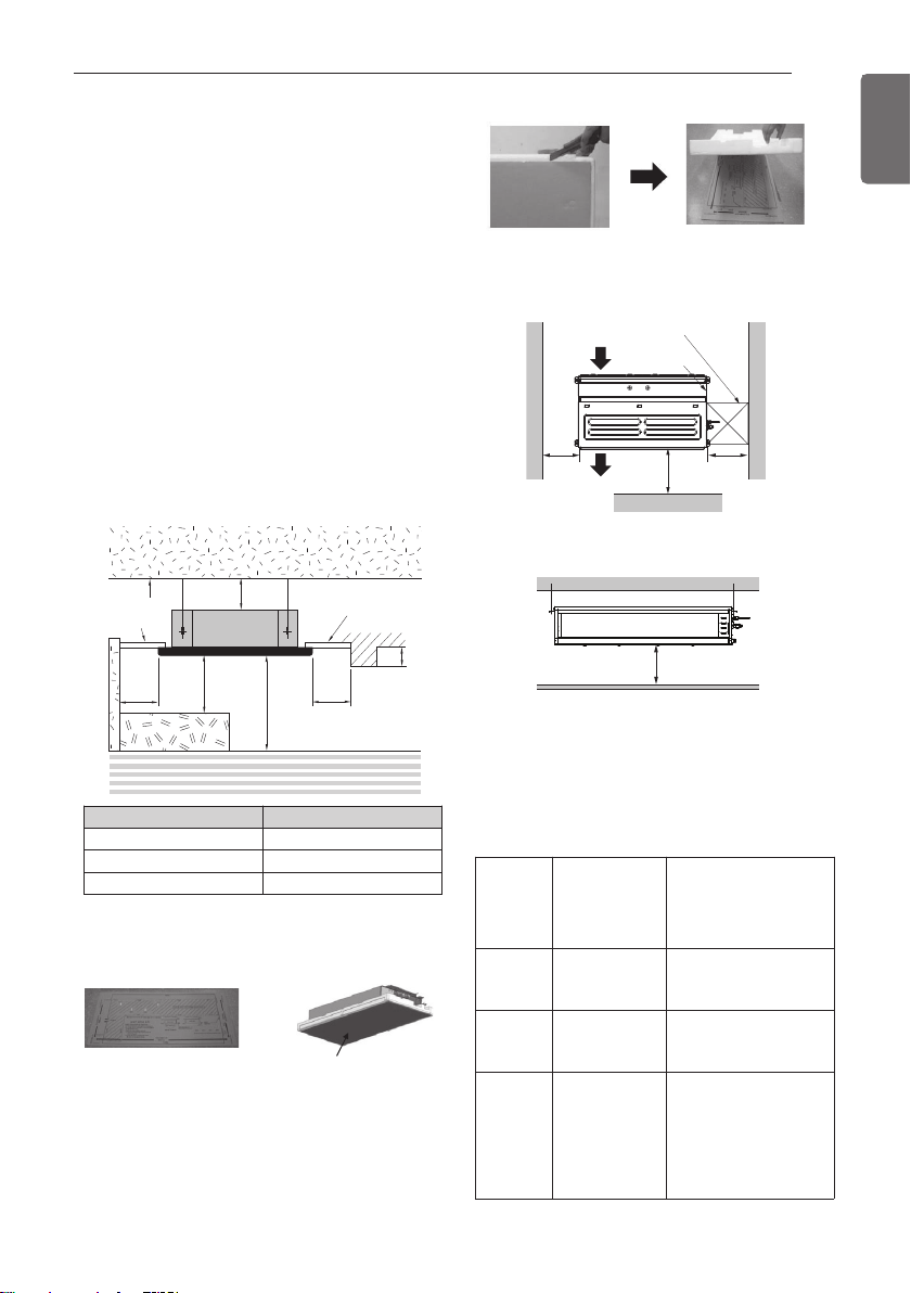
Installation Places for Indoor unit
• Suitable dimension "H" is necessary to get a
slope to drain as shown in the figure.
Unit : mm
Ceiling
Ceiling Board
Ceiling Board
H
1 000
or more
500 or
more
500 or
more
300 or less
At least 1 800
H or less
Floor
10 or
more
Chassis H
TU/TT 3 300
TQ/TR/TP 3 600
TN/TM 4 200
H=20 or more
(unit: mm)
Front
Inspection hole 600 x 600
Control box
1 000
Air outlet vents
Air inlet vents
600
600
(unit: mm)
Top view
Side view
- There should not be any heat source or steam
near the unit.
- There should not be any obstacles to prevent the
air circulation.
- A place where air circulation in the room will be
good.
- A place where drainage can be easily obtained.
- A place where noise prevention is taken into
consideration.
- Do not install the unit near the door way.
- Ensure the spaces indicated by arrows from the
wall, ceiling, or other obstacles.
- The indoor unit must keep the maintenance space.
* Please use an annexed sheet or the
corrugated cardboard on the bottom of
packing as installation sheet.
* When using the bottom sheet, please use it
after separating the installation sheet from
packing of the product floor by using a knife
etc as a picture below.
Annexed sheet
Or
Packing corrugated
cardboard on the
bottom
[Inspection Hole Standard]
Number
of
Inspection
hole
Distance
between
False ceiling &
Actual ceiling
Remarks
1
More than 100
cm
Sufficient space in the
ceiling for servicing.
2
20 cm to 100
cm
Insufficient space.
Difficult for servicing
Hole size
should be
more
than the
size of
IDU.
Less than 20
cm
Minimum height for
motor replacement.
* The feature can be changed according to
type of model.
12
INSTALLATION PLACES
ENGLISH
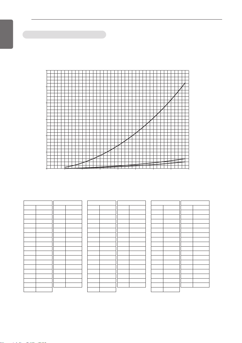
- The appliance shall be installed, operated and stored in a room with a floor area larger than the
minimum area.
- Use the graph of table to determine the minimum area.
- m : Total refrigerant amount in the system
- Total refrigerant amount : factory refrigerant charge + additional refrigerant amount
- Amin : minimum area for installation
Minimum floor area (for R32)
0
100
200
300
400
500
600
Amin (m
2
)
m (kg)
0 1.224 2 3 4 5 6 7 8
Floor standing
Wall mounted
Ceiling mounted
Floor location
m (kg) Amin (m
2
)
< 1.224
-
1.224 12.9
1.4 16.82
1.6 21.97
1.8 27.80
2 34.32
2.2 41.53
2.4 49.42
2.6 58.00
2.8 67.27
3 77.22
3.2 87.86
3.4 99.19
3.6 111.20
3.8 123.90
4 137.29
4.2 151.36
4.4 166.12
Floor location
m (kg) Amin (m
2
)
4.6 181.56
4.8 197.70
5 214.51
5.2 232.02
5.4 250.21
5.6 269.09
5.8 288.65
6 308.90
6.2 329.84
6.4 351.46
6.6 373.77
6.8 396.76
7 420.45
7.2 444.81
7.4 469.87
7.6 495.61
7.8 522.04
Wall mounted
m (kg) Amin (m
2
)
< 1.224
-
1.224 1.43
1.4 1.87
1.6 2.44
1.8 3.09
2 3.81
2.2 4.61
2.4 5.49
2.6 6.44
2.8 7.47
3 8.58
3.2 9.76
3.4 11.02
3.6 12.36
3.8 13.77
4 15.25
4.2 16.82
4.4 18.46
Wall mounted
m (kg) Amin (m
2
)
4.6 20.17
4.8 21.97
5 23.83
5.2 25.78
5.4 27.80
5.6 29.90
5.8 32.07
6 34.32
6.2 36.65
6.4 39.05
6.6 41.53
6.8 44.08
7 46.72
7.2 49.42
7.4 52.21
7.6 55.07
7.8 58.00
Ceiling Mounted
m (kg) Amin (m
2
)
< 1.224
-
1.224 0.956
1.4 1.25
1.6 1.63
1.8 2.07
2 2.55
2.2 3.09
2.4 3.68
2.6 4.31
2.8 5.00
3 5.74
3.2 6.54
3.4 7.38
3.6 8.27
3.8 9.22
4 10.21
4.2 11.26
4.4 12.36
Ceiling Mounted
m (kg) Amin (m
2
)
4.6 13.50
4.8 14.70
5 15.96
5.2 17.26
5.4 18.61
5.6 20.01
5.8 21.47
6 22.98
6.2 24.53
6.4 26.14
6.6 27.80
6.8 29.51
7 31.27
7.2 33.09
7.4 34.95
7.6 36.86
7.8 38.83
INSTALLATION PLACES
13
ENGLISH
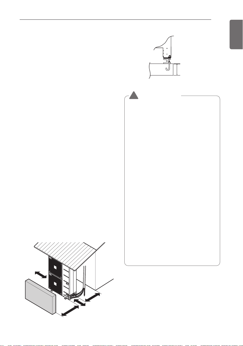
- If an awning is built over the unit to prevent
direct sunlight or rain exposure, make sure that
heat radiation from the condenser is not
restricted.
- Ensure that the spaces indicated by arrows
around front, back and side of the unit are
respected.
- Do not place animals and plants in the path of
the warm air.
- Take the air conditioner weight into account and
select a place where noise and vibration are
minimum.
- Select a place so that the warm air and noise
from the air conditioner do not disturb
neighbors.
- Select a place that can sufficiently endure
the weight and vibration of the outdoor unit
and where even installation is possible.
- Select a place that has no direct impact of
snow or rain
- Select a place with no danger of snowfall or
icicle drop
- Select a place without weak floor or base
such as decrepit part of the building or with a
lot of snow accumulation
- Install at a place with fluent water draining to
prevent damage from localized heavy rain
and avoid frequent flooded area.
You need to select adequate installation
location considering the following conditions,
and make sure to acquire the consent of the
user.
Installation Places for
Outdoor Unit
More than
300 mm
Fence or
obstacles
More than 700 mm
More than 600 mm
More than
More than
300 mm
300 mm
More than
300 mm
Sunroof
A > 200 mm
Be very careful while carrying the
product.
• Do not have only one person carry
product if it is more than 20 kg (44 lbs).
• PP bands are used to pack some
products. Do not use them as a mean
for transportation because they are
dangerous.
• Do not touch heat exchanger fins with
your bare hands. Otherwise you may
get a cut in your hands.
• Tear plastic packaging bag and scrap it
so that children cannot play with it.
Otherwise plastic packaging bag may
suffocate children to death.
• When carrying in Outdoor Unit, be sure
to support it at four points. Carrying in
and lifting with 3-point support may
make Outdoor Unit unstable, resulting
in a fall.
• Use 2 belts of at least 8 m (26.2 ft)
long.
• Place extra cloth or boards in the
locations where the casing comes in
contact with the sling to prevent
damage.
•
Hoist the unit making sure it is being
lifted at its center of gravity.
CAUTION
!
14
INSTALLATION PLACES
ENGLISH
Sea wind
Sea wind
• Air conditioners should not be installed
in areas where corrosive gases, such as
acid or alkaline gas, are produced.
• Do not install the product where it could
be exposed to sea wind (salty wind)
directly. It can result corrosion on the
product. Corrosion, particularly on the
condenser and evaporator fins, could
cause product malfunction or inefficient
performance.
• If outdoor unit is installed close to the
seaside, it should avoid direct exposure
to the sea wind. Otherwise it needs
additional anticorrosion treatment on the
heat exchanger.
CAUTION
!
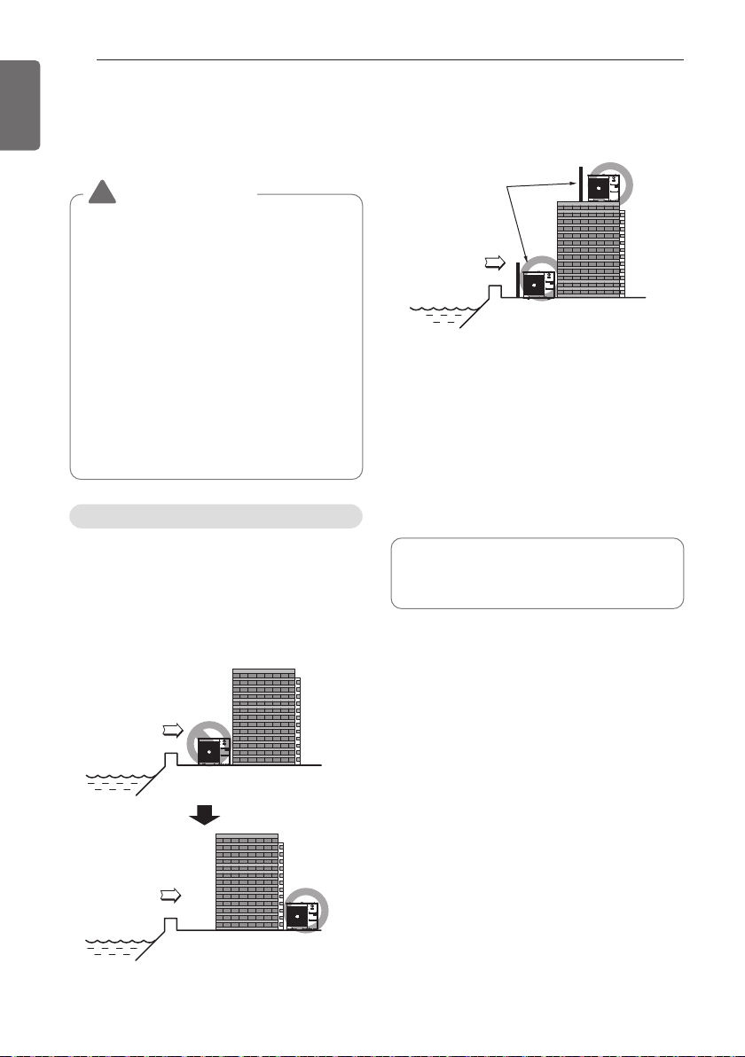
- It should be strong enough like concrete to
prevent the sea wind from the sea.
- The height and width should be more than
150 % of the outdoor unit.
- More than 70 cm of space should be kept
between outdoor unit and the windbreak for
easy air flow.
Place with fluent water draining
- Install at a place with fluent water draining to
prevent damage from localized heavy rain
and avoid frequent flooded area.
Seasonal Wind and Cautions
in Winter
- Sufficient measures are required in a snow
area or severe cold area in winter so that
product can operate well.
- Get ready for seasonal wind or snow in
winter even in other areas.
- Install a suction and discharge duct not to let
in snow or rain.
- Install the outdoor unit not to come in
contact with snow directly. If snow piles up
and freezes on the air suction hole, the
system may malfunction. If it is installed at
snowy area, attach the hood to the system.
- Install the outdoor unit at the higher
installation console by 50 cm than the
average snowfall (annual average snowfall) if
it is installed at the area with much snowfall.
- Where snow accumulated on the upper part
of the Outdoor Unit by more than 10 cm,
always remove snow for operation.
In case, to install the outdoor unit on the
seaside, set up a windbreak not to be
exposed to the sea wind.
In case, to install the outdoor unit on the
seaside, set If the outdoor unit is to be
installed close to the seaside, direct exposure
to the sea wind should be avoided.
Install the outdoor unit on the opposite side of
the sea wind direction. a windbreak not to be
exposed to the sea wind.
Selecting the location (Outdoor Unit)
• Periodic ( more than once/year ) cleaning
of the dust or salt particles stuck on the
heat exchanger by using water.
Sea wind
Windbreak
Installation Guide at the
Seaside
THE INDOOR UNIT INSTALLATION
15
ENGLISH
CAUTION
!
• This air-conditioner uses a drain pump.
• Install the unit horizontally using a level
gauge.
• During the installation, care should be
taken not to damage electric wires.
- Select and mark the position for fixing bolts and
piping hole.
- Decide the position for fixing bolts slightly tilted to
the drain direction after considering the direction
of drain hose.
- Drill the hole for anchor bolt on the wall.
NOTE
!
Avoid the following installation location.
1 Such places as restaurants and kitchen where
considerable amount of oil steam and flour is
generated. These may cause heat exchange
efficiency reduction, or water drops, drain
pump mal-function. In these cases, take the
following actions;
- Make sure that ventilation fan is enough to
cover all noxious gases from this place.
- Ensure enough distance from the cooking
room to install the air conditioner in such a
place where it may not suck oily steam.
2 Avoid installng air conditioner in such places
where cooking oil or iron powder is generated.
3 Avoid places where inflammable gas is
generated.
4 Avoid place where noxious gas is generated.
5 Avoid places near high frequency generators.
Cooking table
Air conditioner
Take enough
distance
Use the ventilation fan for smoke-collecting
hood with sufficient capacity.
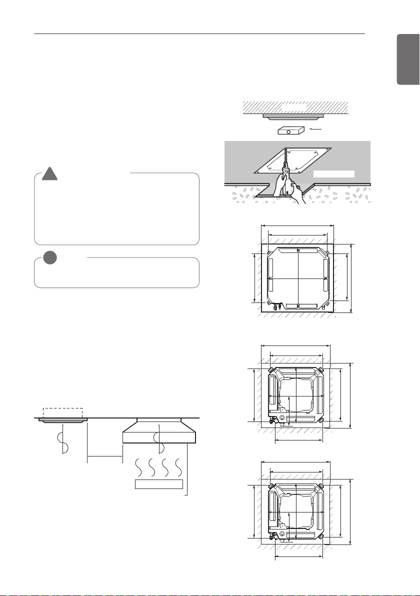
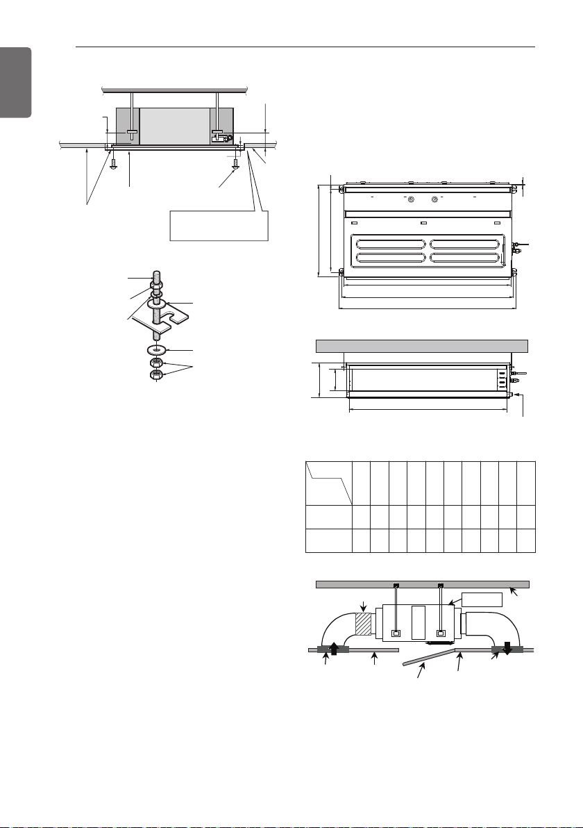
Level gauge
Ceiling
Ceiling board
Unit:mm
875(Ceiling opening)
Panel size : 950 X 950 mm
Panel size : 700 X 700 mm
787
684
671
875 (Ceiling opening)
840
840
[TM/TN/TP Chassis] (Unit : mm)
[TQ/TR Chassis] (Unit : mm)
585~660(Ceiling opening)
517
461
517
585~660(Ceiling opening)
523
570
570
319
Unit:mm
Panel size : 620 X 620 mm
600(Ceiling opening)
517
461
517
600(Ceiling opening)
523
570
570
319
THE INDOOR UNIT INSTALLATION
Position of Suspension Bolt
Ceiling Cassette Type
16
THE INDOOR UNIT INSTALLATION
ENGLISH
Set screw of
paper model (4 pieces)
Paper model
for installation
Ceiling
board
150 mm
Ceiling board
Ceiling
Keep the
length of the
bolt from
the bracket
to 40 mm
Open the ceiling board
along the outer edge of the
paper model
Air Conditioner body
Keep the length of 15~18 mm
between the air conditioner
bottom surface and the ceiling
surface
Adjust the
same height
Flat washer for M10
(accessory)
Flat washer for M10
(accessory)
Hanging bolt
(W3/8 or M10)
Nut
(W3/8 or M10)
Nut
(W3/8 or M10)
Spring washer
(M10)
* The feature can be changed according to
type of model.
Ceiling Concealed Duct Type - Mid
static
- Apply a joint-canvas between the unit and
duct to absorb unnecessary vibration.
- Apply a filter Accessory at air return hole.
C
E
G
D
A
J
B
Drainage hole
F
I
H
Inspection Port
Indoor Unit
Ceiling
Canvas Duct
Air Intake Port
Ceiling Board
Ceiling Board
Air Discharge Port
Discharge
Flexible Duct
Intake
Duct
Dimension
Chassis
A B C D E F G H I J
M1
933.4 971.6 619.2
700 30 270 15.2
858 201.4
900
M2
1 283.4 1 321.6 619.2
689.6
30 270 15.2
1 208 201.4
1 250
(Unit: mm)
THE INDOOR UNIT INSTALLATION
17
ENGLISH
Position of console Bolt
- A place where the unit will be leveled and
that can support the weight of the unit.
- A place where the unit can withstand its
vibration.
- A place where service can be easily
performed.
M10 Nut
M10 SP. washer
M10 washer
X 4
X 4
(Local
supply)
X 4
M10 Nut
M10 SP. washer
M10 washer
X 4
X 4
(Local
supply)
X 4
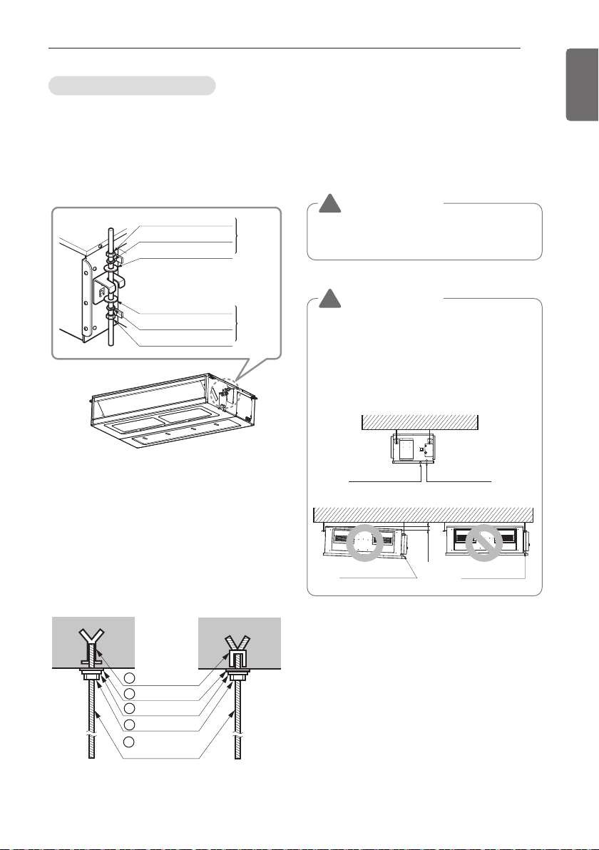
- Insert the set anchor and washer onto the
suspension bolts for locking the suspension
bolts on the ceiling.
- Mount the suspension bolts to the set
anchor firmly.
- Secure the installation plates onto the
suspension bolts (adjust level roughly) using
nuts, washers and spring washers.
1 Set anchor
Old building New building
2 Plate washer
3 Spring washer
4 Nut
5 Suspension
bolts
• Local supply
① Set anchor
② Plate washer - M10
③ Spring washer - M10
④ Nut - W3/8 or M10
⑤ Suspension bolt - W3/8 or M10
CAUTION
• Tighten the nut and bolt top revent unit
falling.
!
CAUTION
1. Install declination of the indoor unit is
very important for the drain of the duct
type airconditioner.
2. Minimum thickness of the insulation
for the connecting pipe shall be 10
mm.
!
1~3 mm
Drainage hole
Drainage hole
Safety drain hole Main drain hole
18
THE INDOOR UNIT INSTALLATION
ENGLISH
Heat Insulation
- Use the heat insulation material for the
refrigerant piping which has an excellent
heat-resistance (over 120 °C).
- Precautions in high humidity circumstance:
This air conditioner has been tested according
to the "KS Standard Conditions with Mist" and
confirmed that there is not any default.
However, if it is operated for a long time in high
humid atmosphere (dew point temperature:
more than 23 °C), water drops are liable to fall.
In this case, add heat insulation material
according to the following procedure:
- Heat insulation material to be prepared...
Adiabatic EPDM or NBR with thickness 10 to
20 mm.
- Stick glass wool on all air conditioners that are
located in ceiling atmosphere.
Indoor
unit
Thermal insulator
(accessory)
Fastening band
(accessory)
Refrigerant
piping
Maintenance
drain port
Upward
routing
not allowed
Pipe clamp
Indoor unit
300mm or less
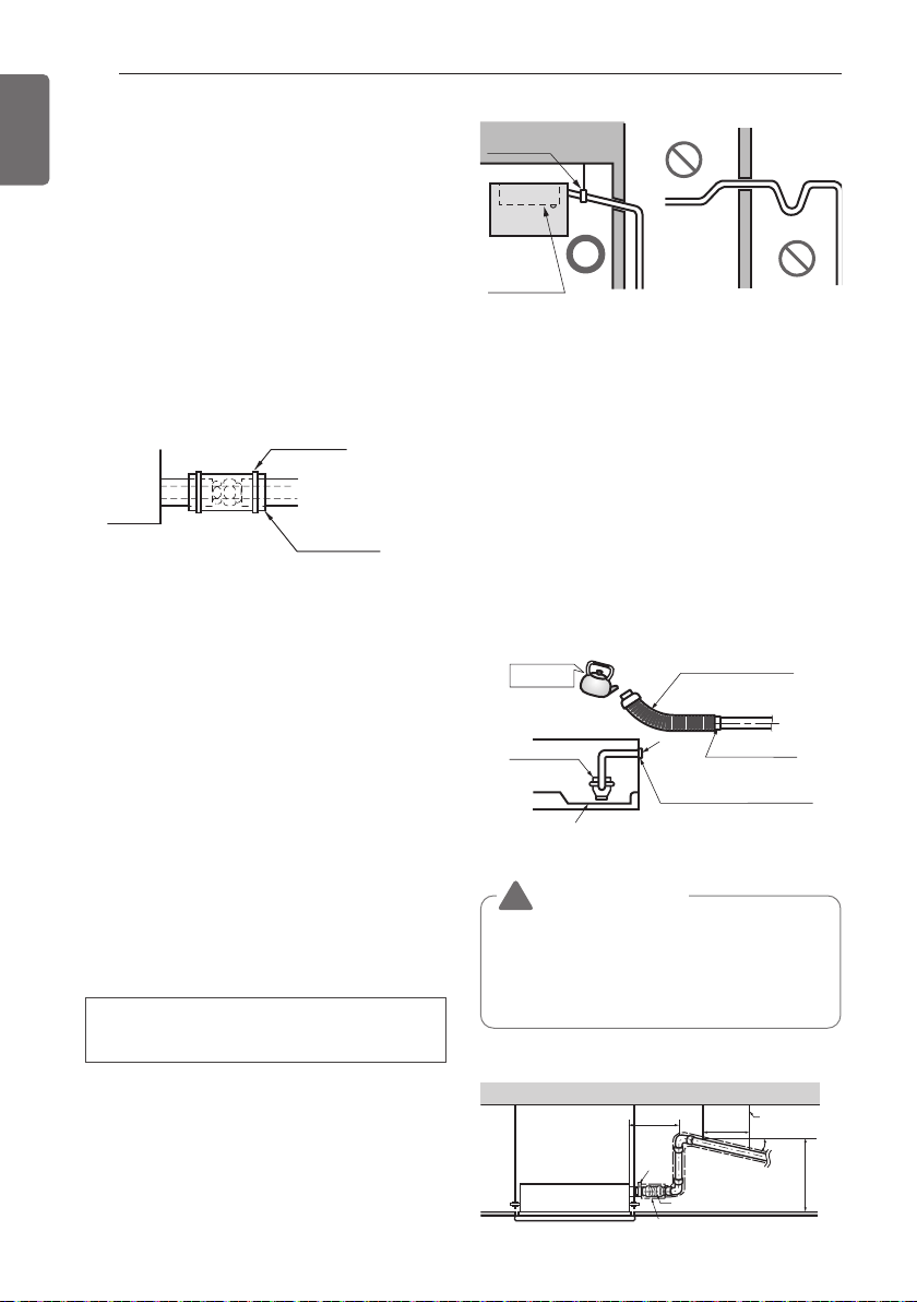
Indoor Unit Drain Piping
- Drain piping must have down-slope (1/50 to
1/100): be sure not to provide up-and-down
slope to prevent reversal flow.
- During drain piping connection, be careful
not to exert extra force on the drain port on
the indoor unit.
- The outside diameter of the drain connection
on the indoor unit is 32 mm.
- Be sure to execute heat insulation on the
drain piping.
- Install the drain raising pipes at a right
angle to the indoor unit and no more than
300 mm from the unit.
Piping material: Polyvinyl chloride pipe
VP-25 and pipe fittings
Drain test
The air conditioner uses a drain pump to drain
water.
Use the following procedure to test the drain
pump operation:
- Connect the main drain pipe to the exterior
and leave it provisionally until the test comes
to an end.
- Feed water to the flexible drain hose and
check the piping for leakage.
- Be sure to check the drain pump for normal
operating and noise when electrical wiring is
complete.
- When the test is complete, connect the
flexible drain hose to the drain port on the
indoor unit.
Feed water
Drain Pump
Drain pan
Flexible drain hose
(accessory)
Main drain pipe
Glue the joint
Drain
port
Drain hose connection
Use the clip (accessory)
1/50~1/100 slope
Hanger
distance
Hanger Bracket
Max 700 mm
Flexible drain hose
Insulation
Metal
clamp
Max 300 mm
1~15 m
CAUTION
The supplied flexible drain hose should
not be curved, neither screwed. The
curved or screwed hose may cause a
leakage of water.
!
WIRING CONNECTION
19
ENGLISH
Electrical Wiring
- All wiring must comply with local
requirements.
- Select a power source that is capable of
supplying the current required by the air
conditioner.
- Use a recognized circuit breaker between
the power source and the unit. A
disconnection device to adequately
disconnect all supply lines must be fitted.
- Capacity of circuit breaker recommended by
authorized personnel only.
Indoor unit
- Remove the control box cover for electrical
connection between the indoor and outdoor
unit.
- Use the cord clamp to fix the cable.
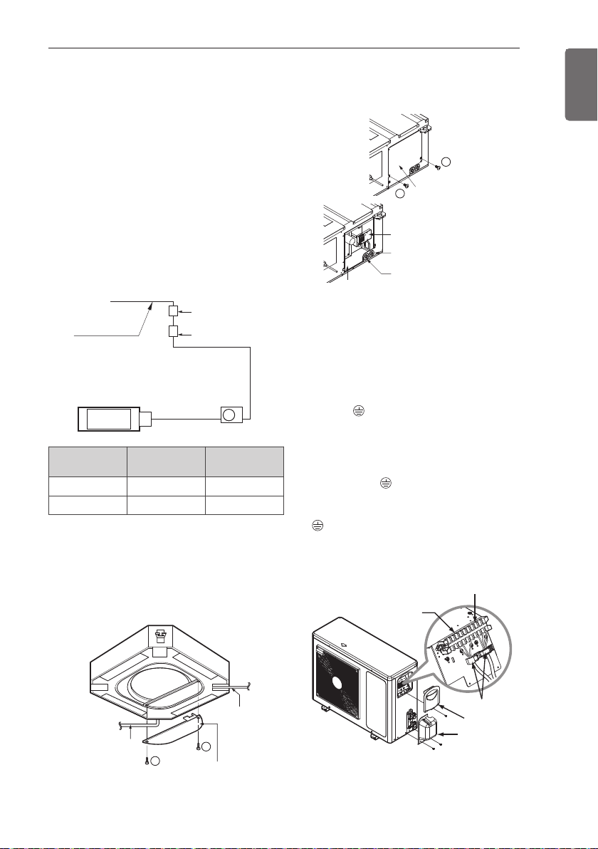
Outdoor unit
- Remove the control cover for wiring
connection.
- Use the cord clamp to fix the cable.
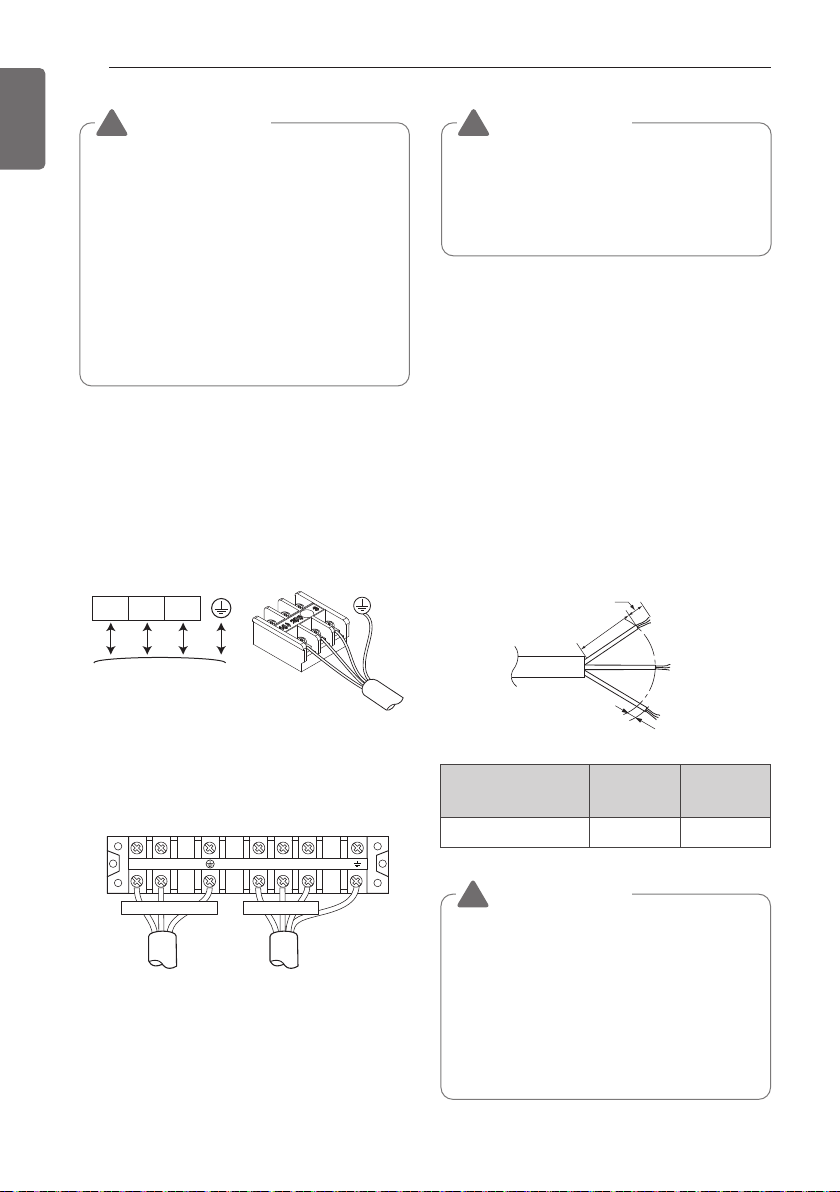
- Earthing work
Case 1 :Terminal block of Outdoor Unit have
mark.
Connect the cable of diameter 1.6 mm
2
or
more to the earthing terminal provided in the
control box and do earthing.
Case 2 :Terminal block of Outdoor Unit don't
have mark.
- Connect the cable of diameter 1.6 mm
2
or
more, to the panel of control box, marked as
and fasten with earth screw.
Outdoor
Indoor
Main
power source
Switch box
Circuit Breaker
Cover control
Tubing Cover
Connecting cable
terminal
Power cord
terminal
Cord clamp
Capacity
(kBtu/h)
Phase(Ø) ELCB
24 1 25 A
36 / 48 1 40 A
WIRING CONNECTION
Remote
controller
cord
Connection cord
between the indoor
unit and the
outdoor unit
Control box cover
(On which the Electric
Wiring Connection is put)
1
1
Control box
Control box cover
(On which the Electric
Wiring Connection is put)
Control terminal board
Remote controller cord
Connection cord between the indoor
unit and the outdoor unit
1
1
20
WIRING CONNECTION
ENGLISH
• The circuit diagram is not subject to
change without notice.
• Be sure to connect wires according to
the wiring diagram.
• Connect the wires firmly, so that not to
be pulled out easily.
• Connect the wires according to color
codes by referring the wiring diagram.
• The Power cable connected to the unit
should be selected according to the
following specifications.
Connecting cables to the Unit
- Connect the wires to the terminals on the
control board individually according to the
outdoor unit connection.
* Ensure that the color of the wires of
outdoor unit.
<Indoor>
* The figure can be changed according to
model.
<Outdoor>
Clamping of cables
- Arrange two power cables on the control
panel.
- First, fasten the clamp with a screw to the
inner boss of control panel.
- For connecting cable to the terminal block,
put the 1.0 mm
2
cable(thinner cable) on the
clamp and tighten it with a plastic clamp to
the other boss of the control panel.
- In Australia, the length of power supply cable
measured from the entry of the power
supply cable to the middle of live pin on the
power plug should be over 1.8 m.
• Make sure that the screws of the
terminal fixed tightly
• Installation work must be performed in
accordance with the national wiring
standards by authorized personnel only
• Supply cable of parts of appliance for
outdoor use shall not be lighter than
polychloroprene sheathed flexible cord
(code designation 60245 IEC 57) or
complied with HD 22.4 S4
• If the supply cable is damaged, it must
be replaced by a special cord or
assembly availible from the
manufacturer of its service agent.
GN/YL
20 mm
35±5 mm
10±3 mm
Capacity
(kBtu/h)
Phase(Ø) Area (mm
2
)
24 / 36 / 48 1 6
1(L) 2(N) 3
Connected to outdoor
unit or B.D. unit.
1(L) 2(N) 1(L) 2(N) 3
POWER SUPPLY TO INDOOR UNIT
CAUTION
!
CAUTION
!
CAUTION
!
WIRING CONNECTION
21
ENGLISH
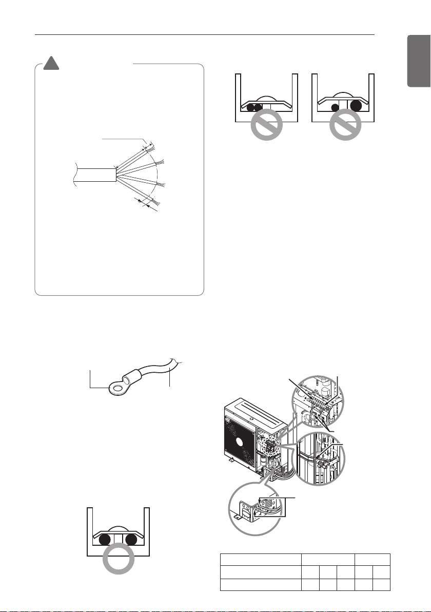
Precautions when laying power
wiring
Use round pressure terminals for connections
to the power terminal block.
When none are available, follow the
instructions below.
- Do not connect wiring of different
thicknesses to the power terminal block.
(Slack in the power wiring may cause
abnormal heat.)
- When connecting wiring which is the same
thickness, do as shown in the figure below.
Power wirer
Round pressure terminal
It is forbidden to
connect two to one
side.
It is forbidden to
connect wiring of
different thicknesses.
Connect same thickness
wiring to both sides.
- For wiring, use the designated power wire
and connect firmly, then secure to prevent
outside pressure being exerted on the
terminal block.
- Use an appropriate screwdriver for tightening
the terinal screws. A screwdriver with a
small head will strip the head and make
proper tighterning impossible.
- Over-tightening the terminal screws may
break them.
CAUTION
The connecting cable connected to the
indoor and outdoor unit should be
complied with the following specifications
(This equipment shall be provided with a
cord set complying with the national
regulation).
!
NORMAL
CROSS-SECTIONAL
AREA 0.75 mm
2
20 mm
35±5 mm
GN/YL
10±3 mm
If the supply cord is damaged, it must be
replaced by a special cord or assembly
available from the manufacturer of its
service agent.
Connecting cables to the
Outdoor Unit
- Remove the side panel from the unit by
loosing screws.
Connect the wires to the terminals on the
control board individually as previous page.
- Secure the cable onto the control board with
the holder (clamp).
- Refix the cover control to the original
position with the screw.
Connecting cable
terminal
Power cord terminal
Cord clamp
Cord clamp
* Make sure the rubber
bushes are Properly used
in knock-out holes after
connecting main Power
cable
CST Duct
Capacity (kBtu/h) 24 36 48 24 36
CMM 13 20 47 14.5 24
* Minimum Rated Air Flow
22
CONNECTING PIPES
ENGLISH
-
Main cause of gas leakage is defect in flaring
work. Carry out correct flaring work in the
following procedure.
- Use the de-oxidised copper as piping
materials to install.
Cut the pipes and the cable.
- Use the accessory piping kit or the pipes
purchased locally.
- Measure the distance between the indoor and
the outdoor unit.
- Cut the pipes a little longer than measured
distance.
- Cut the cable 1.5 m longer than the pipe
length.
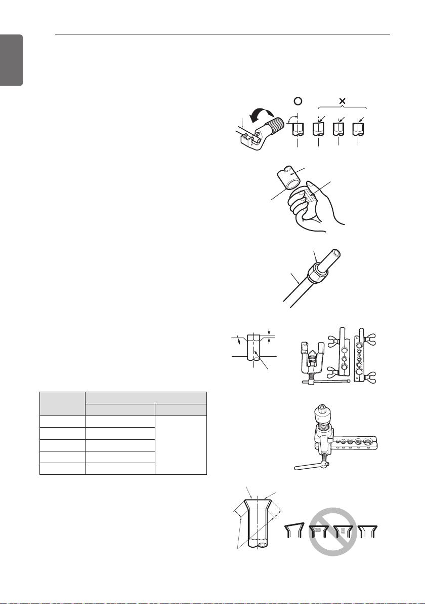
Burrs removal
- Completely remove all burrs from the cut
cross section of pipe/tube.
- Put the end of the copper tube/pipe to
downward direction as you remove burrs in
order to avoid to let burrs drop in the tubing.
Putting nut on
-
Remove flare nuts attached to indoor and
outdoor units, than put them on pipe/tube
having completed burr removal. (Not possible
to put them on after flaring work)
Flaring work
- Carry out flaring work using dedicated flaring
tool for R32 as shown below.
Firmly hold copper tube in a bar(or clamp) as
indicated dimension in the table above.
Check
- Compare the flared work with figure below.
- If flare is noted to be defective, cut off the
flared section and do flaring work again.
Inclined
Inside is shining without scratches.
Smooth all round
Even length
all round
Surface
damaged
Cracked Uneven
thickness
= Improper flaring =
Flare nut
Copper tube
Pipe
Reamer
Point down
Copper
tube
90 °
Slanted Uneven Rough
Preparation of Piping
CONNECTING PIPES
Bar
Copper pipe
"A"
<Wing nut type>
<Clutch type>
Pipe diameter
Inch (mm)
A inch (mm)
Wing nut type Clutch type
Ø 1/4 (Ø 6.35)
0.04~0.05 (1.1~1.3)
0~0.02
(0~0.5)
Ø 3/8 (Ø 9.52)
0.06~0.07 (1.5~1.7)
Ø 1/2 (Ø 12.7)
0.06~0.07 (1.6~1.8)
Ø 5/8 (Ø 15.88)
0.06~0.07 (1.6~1.8)
Ø 3/4 (Ø 19.05)
0.07~0.08 (1.9~2.1)
CONNECTING PIPES
23
ENGLISH
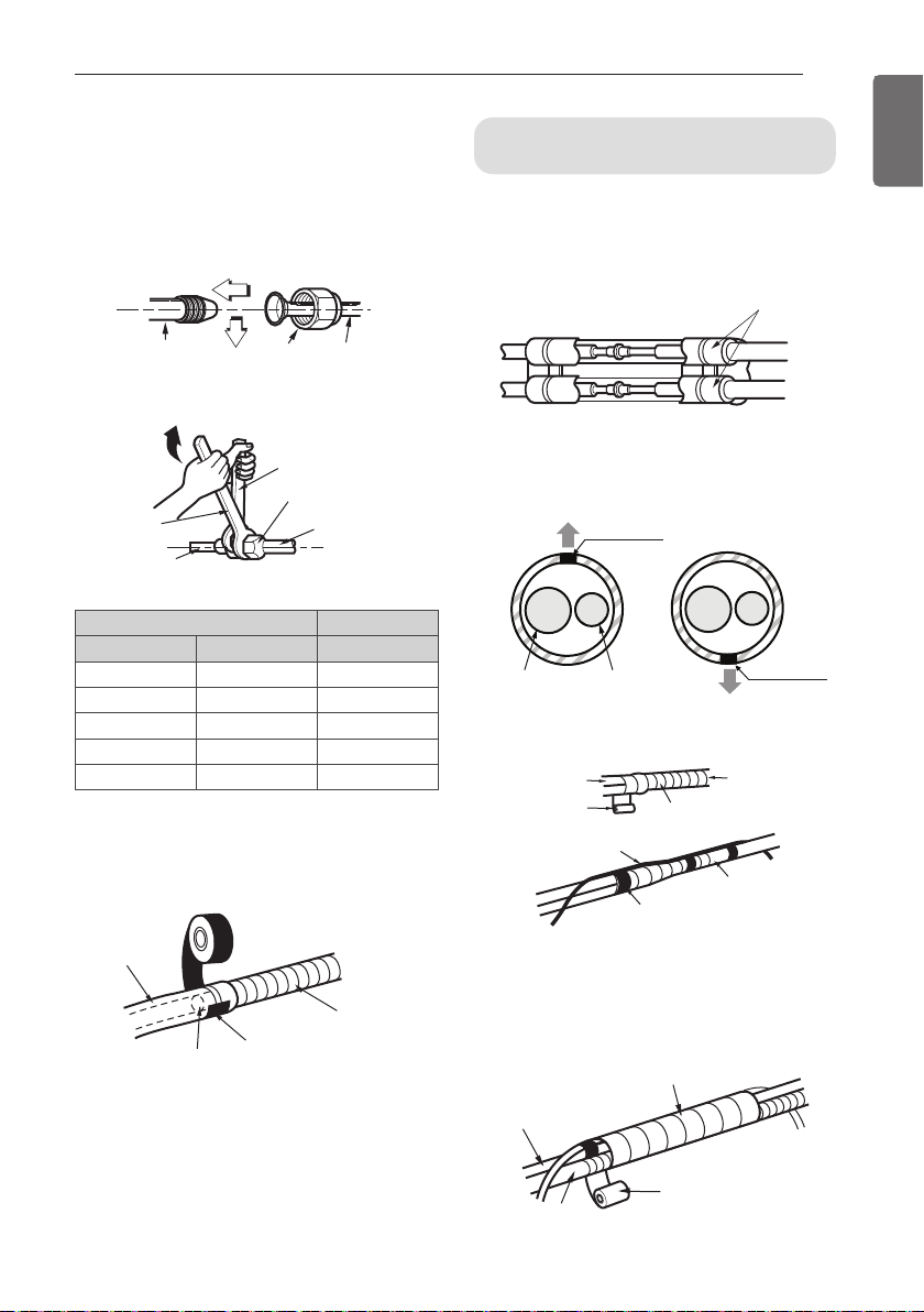
Connecting the pipings to the
indoor unit and drain hose to
drain pipe
- Align the center of the pipings and
sufficiently tighten the flare nut by hand.
- Tighten the flare nut with a wrench.
- When extending the drain hose at the indoor
unit, install the drain pipe.
Indoor unit tubing Flare nut Pipings
Torque wrench
Indoor unit tubing
Spanner (fixed)
Connection pipe
Flare nut
Vinyl tape(narrow)
Adhesive
Drain pipe
Indoor unit drain hose
Outside diameter Torque
mm inch kg
.
m
Ø 6.35 1/4 1.8~2.5
Ø 9.52 3/8 3.4~4.2
Ø 12.7 1/2 5.5~6.6
Ø 15.88 5/8 6.6~8.2
Ø 19.05 3/4 9.9~12.1
1 Overlap the connection pipe insulation
material and the indoor unit pipe insulation
material. Bind them together with vinyl
tape so that there may be no gap.
Wrap the insulation material
around the connecting portion.
Insulation material
2 Set the tubing cutting line upward.
Wrap the area which accommodates the
rear piping housing section with vinyl tape.
3 Bundle the piping and drain hose together
by wrapping them with vinyl tape sufficient
enough to cover where they fit into the
rear piping housing section.
Wrap with vinyl tape
Drain hose
Pipe
Vinyl tape(wide)
Gas Pipe
Liquid Pipe
Cutting Line
Cutting Line
Good Case Bad Case
* Tubing cutting line have to be upward.
Vinyl tape(narrow)
Connection pipe
Connecting cable
Vinyl tape (wide)
Wrap with vinyl tape
Indoor unit pipe
Pipe
24
CONNECTING PIPES
ENGLISH
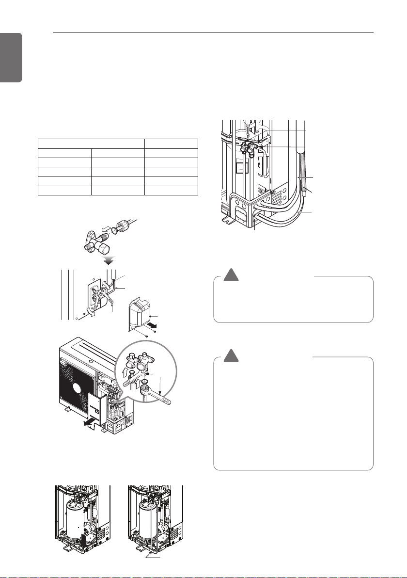
Connection of piping - Outdoor
- Align the center of the piping and sufficiently
tighten the flare nut by hand.
- Finally, tighten the flare nut with torque
wrench until the wrench clicks.
When tightening the flare nut with torque
wrench ensure the direction for tightening
follows the arrow on the wrench.
* When tighten the pipe, hold the haxagonal
body.
- When connecting in a downward direction,
knock out the knock-out hole of the base
pan. (refer to figure 2)
Preventing foreign objects from entering
(Figure3)
- Plug the pipe through-holes with putty or
insulation material(procured locally)to stop up
all gaps,as shown in the figure 3.
Continuous
TorqueTorque
wrenchwrench
(250mm) (250mm)
Torque
wrench
(250 mm)
Torque
wrench
(250mm)
Torque wrench
Outdoor unit
Gas side piping
(Bigger Dia.)
Liquid side piping
(Smaller Dia.)
Tubing Cover
Knock-out Base pan
<Figure 2>
Gas side piping
Liquid side piping
Drain hose
Connecting wire
Connection pipe
<Figure 3>
Resin, Clay, Putty or insulating material
(produced locally)
Insects or small animals entering the
outdoor unit may cause a short circuit in
the electrical box.
CAUTION
!
Outside diameter
Torque
mm inch kg·m
Ø 6.35 1/4 1.8~2.5
Ø 9.52 3/8 3.4~4.2
Ø 12.7 1/2 5.5~6.6
Ø 15.88 5/8 6.6~8.2
(for R32)
•
A brazed, welded, or mechanical
connection shall be made before opening
the valves to permit refrigerant to flow
between the refrigerating system parts.
• When flared joints are reused indoors,
the flare part shall be re-fabricated.
• When mechanical connectors are
reused indoors, sealing parts shall be
renewed.
CAUTION
!
CONNECTING PIPES
25
ENGLISH
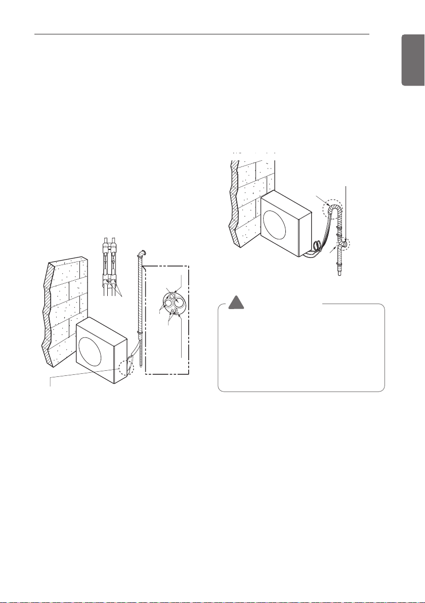
Forming the piping
Form the piping by wrapping the connecting
portion of the indoor unit with insulation
material and secure it with two kinds of vinyl
tape.
- If you want to connect an additional drain
hose, the end of the drain outlet should be
routed above the ground. Secure the drain
hose appropriately.
In cases where the outdoor unit is installed
below the indoor unit perform the following.
1 Tape the piping, drain hose and connecting
cable from down to up.
2 Secure the tapped piping along the exterior
wall using saddle or equivalent.
In cases where the Outdoor unit is installed
above the Indoor unit perform the following.
1 Tape the piping and connecting cable from
down to up.
2 Secure the taped piping along the exterior
wall. Form a trap to prevent water entering
the room.
3 Fix the piping onto the wall by saddle or
equivalent.
Trap
Plastic
band
Seal a small
opening around
the pipings with
gum type sealer.
TrapTrapTrap
Seal a small opening Seal a small opening
around the pipings around the pipings
with gum type sealer.with gum type sealer.
Seal a small opening
around the pipings
with gum type sealant.
OUTDOOR
UNIT
OUTDOOROUTDOOR
UNITUNIT
OUTDOOR
UNIT
• Trap is required to prevent water from entering
into electrical parts.
Taping
Drain hose
Pipings
Connecting
cable
Power supply
cord
PlasticPlastic
bandband
Plastic
band
Seal a small Seal a small
opening around opening around
the pipings with the pipings with
gum type sealer.gum type sealer.
Seal a small
opening around
the pipings with
gum type sealant.
Trap
Seal a small opening
around the pipings
with gum type sealer.
OUTDOOROUTDOOR
UNITUNIT
OUTDOOR
UNIT
OUTDOOR
UNIT
•
Refrigerant tubing shall be protected or
enclosed to avoid damage.
•
Flexible refrigerant connectors (such as
connecting lines between the indoor and
outdoor unit) that may be displaced
during normal operations shall be
protected against mechanical damage.
CAUTION
!
26
PIPING LENGTH AND THE ELEVATION
ENGLISH
Outdoor unit
Indoor unit
A
B
Outdoor uni
t
Indoor unit
A
B
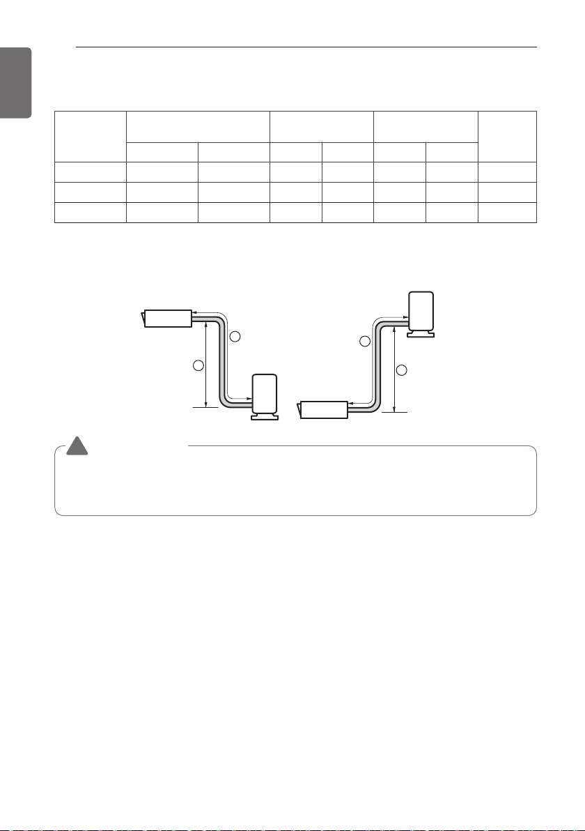
• Capacity is based on standard length and maximun allowance length is on the basis of
reliability.
• Improper refrigerant charge may result in abnormal cycle.
PIPING LENGTH AND THE ELEVATION
Capacity
(kBtu/h)
Pipe Size
mm(inch)
Length A(m) Elevation B(m)
*Additional
refrigerant
(g/m)
Gas Liquid Standard Max. Standard Max.
24 Ø 15.88 (5/8) Ø 9.52 (3/8) 7.5 50 5 30 35
36 Ø 15.88 (5/8) Ø 9.52 (3/8) 7.5 85 5 30 40
48 Ø 15.88 (5/8) Ø 9.52 (3/8) 7.5 85 5 30 40
If installed tube is shorter than 7.5 m, additional charging is not necessary
Additional Refrigerant = (A - 7.5) x Additional refrigerant (g)
CAUTION
!
INSTALLATION OF DECORATIVE PANEL(ACCESSORY)
27
ENGLISH
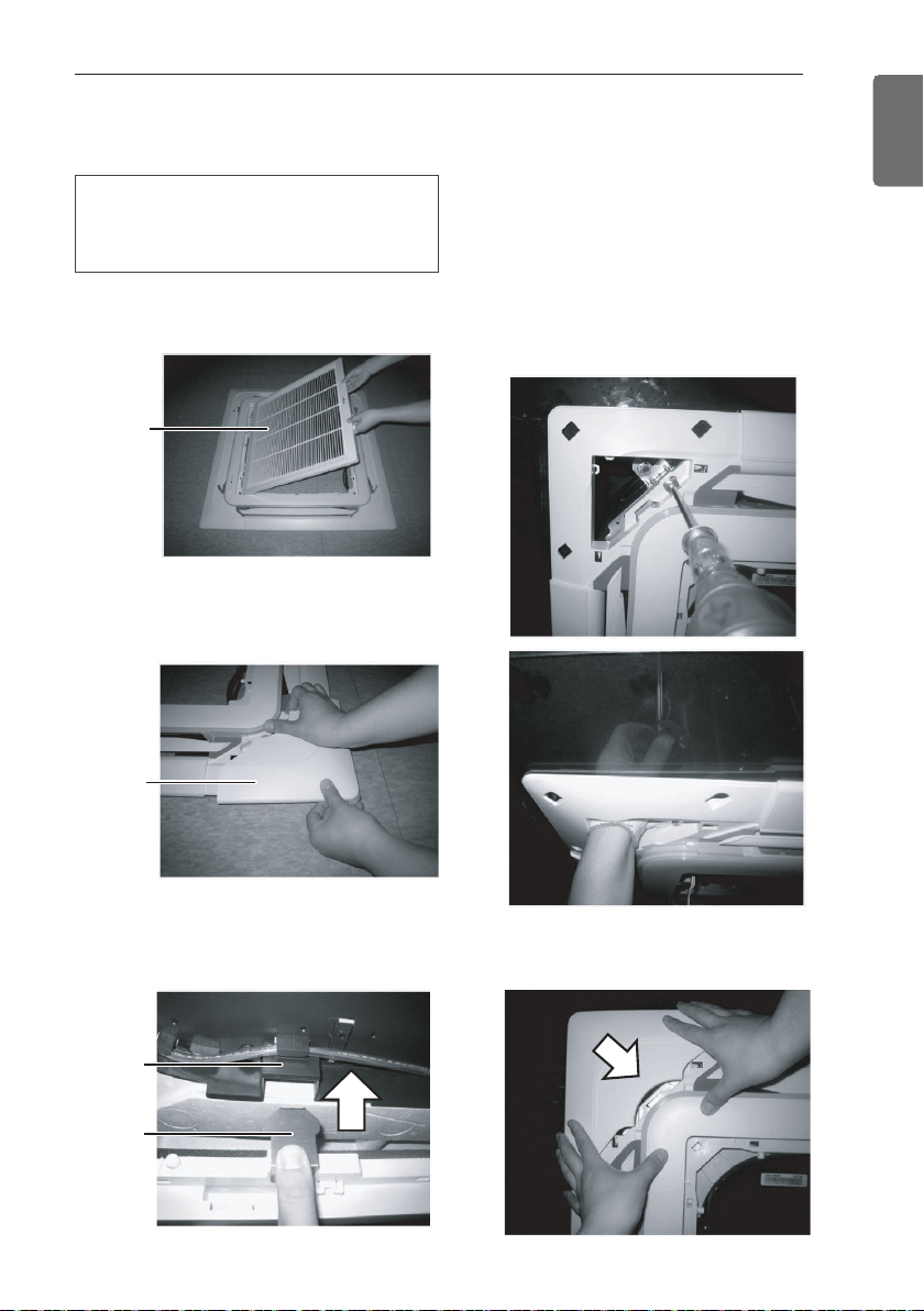
INSTALLATION OF DECORATIVE PANEL(ACCESSORY)
The decorative panel has its installation
direction.
Before installing the decorative panel,
always remove the paper template.
1 Remove the packing and take out air inlet
grille from front panel.
Front
grille
2 Remove the Corner covers of the panel.
Coner
cover
3 Fit the panel on the unit by inserting hooks
as shown in picture.
5 Fit the corner covers.
4 Insert two screws on diagonal corners of
panel. Do not tighten the bolts completely.
(The fixing screws are included in the
indoor unit box.)
Check the alignment of panel with the
ceiling. Height can be adjusted using
hanging bolts as shown in picture. Insert
the other two screws and tighten all
screws completely.
Hook
clip
Hook
28
INSTALLATION OF DECORATIVE PANEL(ACCESSORY)
ENGLISH
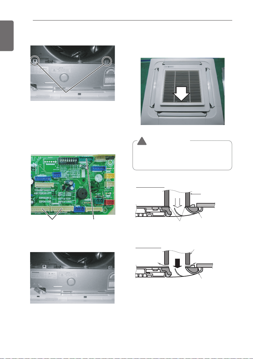
6 Open two screws of control panel cover.
Screw
7 Connect one display connector and two
vane control connectors of front panel to
indoor unit PCB.
The position marking on PCB is as:
Display connector : CN-DISPLAY
Vane control connector: CN-VANE 1,2
8 Close the cover for control box.
9 Install the air inlet grille and Filter on the
panel.
CN-VANE 1,2
CN-DISPLAY
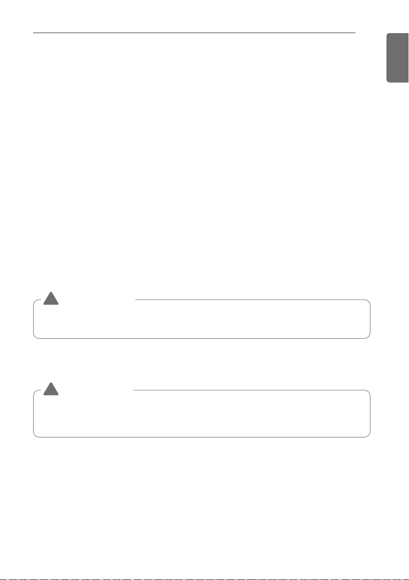
Air conditioner
unit
Decorative panel
Fit the insulator (this part) and
be careful for cool air leakage
Good example
Ceiling
board
Ceiling
board
Decorative
panel
Air
Cool air leakage
(no good)
Bad example
Air conditioner unit
CAUTION
!
Install certainly the decorative panel.
Cool air leakage causes sweating.
Water drops fall.
LEAKAGE TEST AND EVACUATION
29
ENGLISH
Air and moisture remaining in the refrigerant system have undesirable effects as indicated below.
- Pressure in the system rises.
- Operating current rises.
- Cooling (or heating) efficiency drops.
- Moisture in the refrigerant circuit may freeze and block capillary tubing.
- Water may lead to corrosion of parts in the refrigeration system.
Therefore, the indoor/outdoor unit and connecting tube must be checked for leak tight, and
vacuumed to remove incondensible gas and moisture in the system.
- Pressurize the system to no more than 3.8 MPa with dry nitrogen gas and close the cylinder
valve when the gauge reading reached 3.8 MPa Next, test for leaks using bubble test solution.
CAUTION
!
Be sure to use a manifold valve for leakage test. If it is not available, use a stop valve for this
purpose. The "Hi" knob of the manifold valve must always be kept close.
CAUTION
!
To avoid nitrogen entering the refrigerant system in a liquid state, the top of the cylinder
must be higher than its bottom when you pressurize the system. Usually, the cylinder is
used in a vertical standing position.
Preparation
- Check that each tube (both liquid and gas side tubes) between the indoor and outdoor units
have been properly connected and all wiring for the test run have been completed. Remove the
service valve caps from both the gas and the liquid side on the outdoor unit. Check that both the
liquid and the gas side service valves on the outdoor unit are kept closed at this stage.
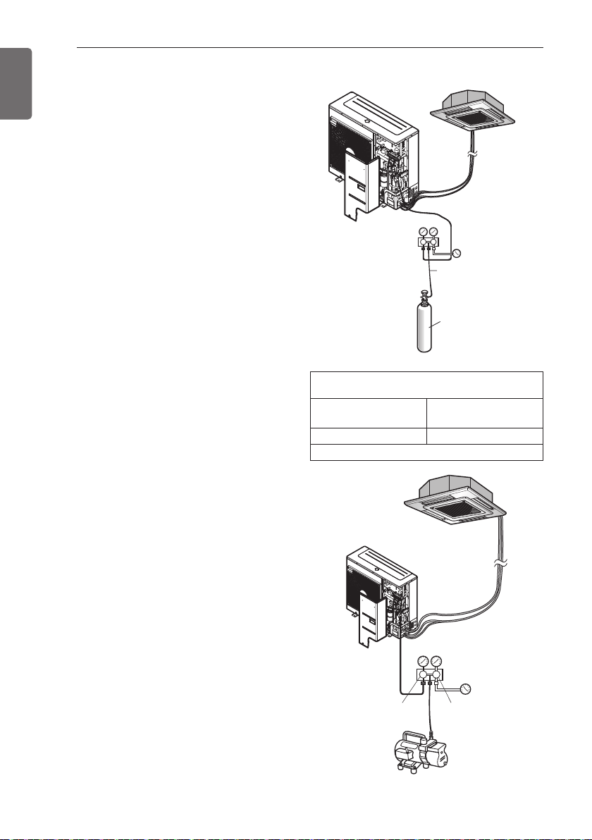
Leakage test
- Connect the manifold valve (with pressure gauges) and dry nitrogen gas cylinder to this service
port with charge hoses.
LEAKAGE TEST AND EVACUATION
30
LEAKAGE TEST AND EVACUATION
ENGLISH
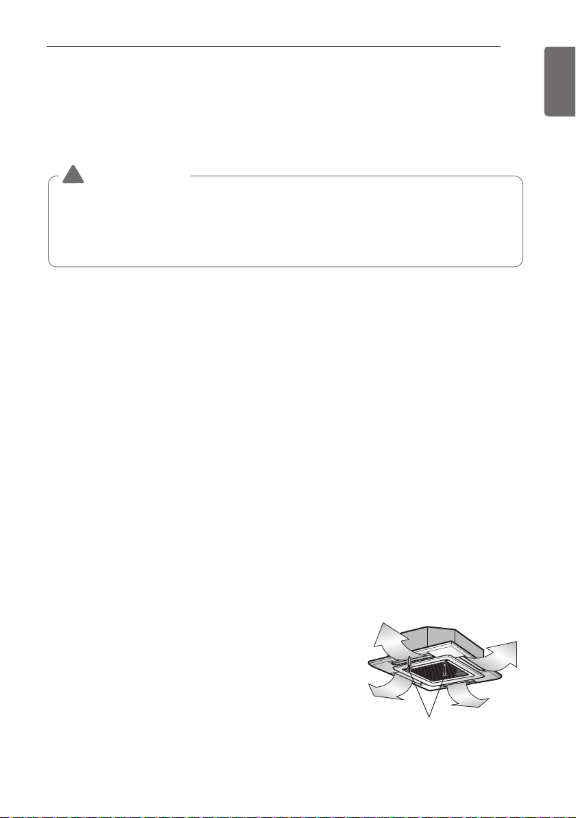
Evacuation
-
Connect the charge hose end described in the
preceding steps to the vacuum pump to
evacuate the tubing and indoor unit. Confirm
the "Lo and Hi" knob of the manifold valve is
open. Then, run the vacuum pump. The
operation time for evacuation varies with
tubing length and capacity of the pump. The
following table shows the time required for
evacuation.
- When the desired vacuum is reached, close
the "Lo and Hi" knob of the manifold valve
and stop the vacuum pump.
Finishing the job
- With a service valve wrench, turn the valve
stem of liquid side valve counter-clockwise
to fully open the valve.
- Turn the valve stem of gas side valve
counter-clockwise to fully open the valve.
- Loosen the charge hose connected to the
gas side service port slightly to release the
pressure, then remove the hose.
- Replace the flare nut and its bonnet on the
gas side service port and fasten the flare nut
securely with an adjustable wrench. This
process is very important to prevent leakage
from the system.
- Replace the valve caps at both gas and liquid
side service valves and fasten them tight.
This completes air purging with a vacuum
pump.
The air conditioner is now ready to test run.
1 Do a leakage test of all joints of the tubing
(both Indoor unit and outdoor unit) and
both gas and liquid side service valves.
Bubbles indicate a leak. Be sure to wipe
off the soap with a clean cloth.
2 After the system is found to be free of
leaks, relieve the nitrogen pressure by
loosening the charge hose connector at
the nitrogen cylinder. When the system
pressure is reduced to normal, disconnect
the hose from the cylinder.
Charge hose
Indoor unit
Outdoor unit
Manifold valve
Pressure
gauge
Nitrogen gas
cylinder (in vertical
standing position)
Lo Hi
Indoor unit
Outdoor unit
Manifold valve
Vacuum pump
Open
Open
Pressure
gauge
Lo Hi
Required time for evacuation when 11.36 l/h
vacuum pump is used
If tubing length is less
than 10 m (33 ft)
If tubing length is
longer than 10 m (33 ft)
30 minutes. or more 60 minutes. or more
0.07 kPa or less
TEST RUNNING
31
ENGLISH
1 Precautions In Test Running
- The initial power supply must provide at least 90 % of the rated voltage.
Otherwise, the air conditioner should not be operated.
CHECK THE FOLLOWING ITEMS WHEN INSTALLATION IS COMPLETE
- After completing work, be sure to measure and record trial run properties, and store measured
data, etc.
- Measuring items are room temperature, outside temperature, suction temperature, blow out
temperature, wind velocity, wind volume, voltage, current, presence of abnormal vibration and
noise, operating pressure, piping temperature, compressive pressure.
- As to the structure and appearance, check following items.
CAUTION
!
• For test run, carry out the cooling operation firstly even during heating season. If heating
operation is carried out firstly, it leads to the trouble of compressor. Then attention must be
paid.
• Carry out the test run more than 5 minutes without fail.
(Test run will be cancelled 18 minutes later automatically)
□Is the circulation of air adequate?
□Is the draining smooth?
□Is the heat insulation complete
(refrigerant and drain piping)?
□Is there any leakage of refrigerant?
□Is the remote controller switch operated?
□Is there any faulty wiring?
□Are not terminal screws loosened?
M4......118 N
.
cm{12 kgf
.
cm}
M5......196 N
.
cm{20 kgf
.
cm}
M6......245 N
.
cm{25 kgf
.
cm}
M8......588 N
.
cm{60 kgf
.
cm}
2 Connection of power supply
- Connect the power supply cord to the independent power supply.
Circuit breaker is required.
- Operate the unit for fifteen minutes or more.
3 Evaluation of the performance
- Measure the temperature of the intake and discharge air.
- Ensure the difference between the intake temperature
and the discharge one is more than 8 °C (Cooling) or
reversely (Heating).
Thermometer
TEST RUNNING
- The test run is started by pressing the room temperature checking button and down timer
button for 3 seconds at the same time.
- To cancel the test run, press any button.

32
TEST RUNNING
ENGLISH
CAUTION
!
After the confirmation of the above conditions, prepare the wiring as follows:
1 Never fail to have an individual power specialized for the air conditioner. As for the
method of wiring, be guided by the circuit diagram pasted on the inside of control box
cover.
2 Provide a circuit breaker switch between power source and the unit.
3 The screw which fasten the wiring in the casing of electrical fittings are liable to come
loose from vibrations to which the unit is subjected during the course of transportation.
Check them and make sure that they are all tightly fastened. (If they are loose, it could
give rise to burn-out of the wires.)
4 Specification of power source
5 Confirm that electrical capacity is sufficient.
6 Be sure that the starting voltage is maintained at more than 90 percent of the rated
voltage marked on the name plate.
7 Confirm that the cable thickness is as specified in the power sources specification.
(Particularly note the relation between cable length and thickness.)
8 Never fail to equip a leakage breaker where it is wet or moist.
9 The following troubles would be caused by voltage drop-down.
- Vibration of a magnetic switch, damage on the contact point there of fuse breaking,
disturbance to the normal function of a overload protection device.
- Proper starting power is not given to the compressor.
HAND OVER
Teach the customer the operation and maintenance procedures, using the operation manual
(air filter cleaning, temperature control, etc.).
INSTALLATION PI485
33
ENGLISH
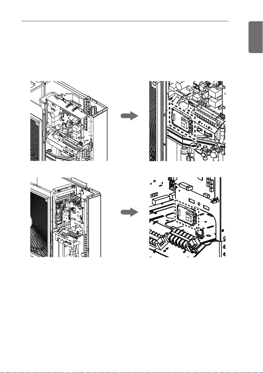
Fix the PI485 PCB as shown in below images.
For detailed installation method refer to PI485 Installation Manual.
24 k
INSTALLATION PI485
36 / 48 k
34
EXTERNAL STATIC PRESSURE
ENGLISH
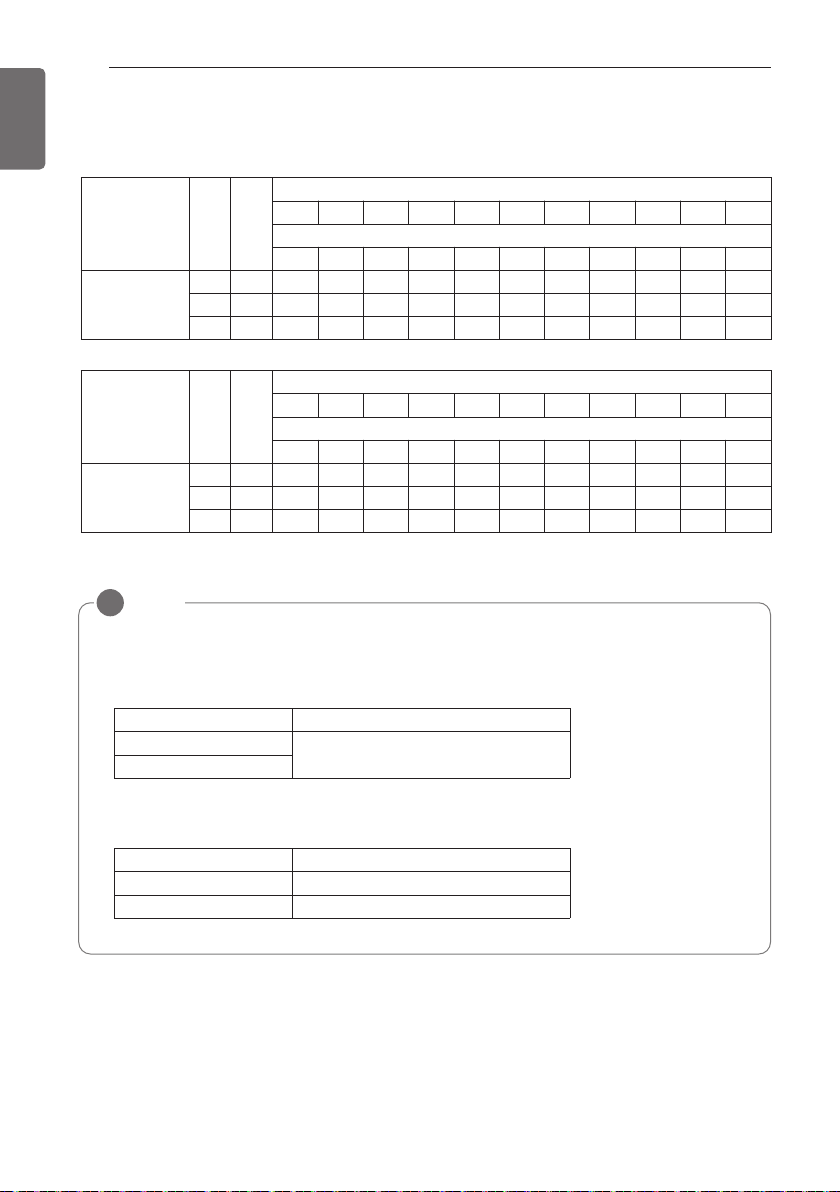
EXTERNAL STATIC PRESSURE
* Only for ceiling concealed duct type
Capacity
(kBtu/h)
Step CMM
Static Pressure[mmAq(Pa)]
2(20) 2.5(25) 3(29) 4(39) 6(59) 8(78) 10(98) 12(118) 13(127) 14(137) 15(147)
Setting Value
32:01 32:02 32:03 32:04 32:05 32:06 32:07 32:08 32:09 32:10 32:11
24
LOW 14.5 76 77 85 89 97 106 114 121 124 127 132
MID 16.5 85 87 90 94 103 111 118 125 128 131 136
HIGH 18 90 92 95 99 108 115 122 129 132 135 138
Capacity
(kBtu/h)
Step CMM
Static Pressure[mmAq(Pa)]
4(39) 5(49) 6(59) 7(69) 8(78) 9(88) 10(98) 11(108) 12(118) 13(127) 15(147)
Setting Value
32:01 32:02 32:03 32:04 32:05 32:06 32:07 32:08 32:09 32:10 32:11
36
LOW 24 88 91 95 100 101 108 113 115 118 121 128
MID 28 93 97 101 105 108 115 118 120 124 127 134
HIGH 32 101 105 109 112 115 119 123 126 128 133 137
NOTE
!
1. Be sure to set the value refering table 2. Unexpected set value will cause mal-function.
2. Table 2 is based at 230 V. According to the fluctuation of voltage, air flow rate varies.
3. Factory Set(External Static Pressure) each Model
* If it is zero static pressure, please set value below Maximum value.
Capacity (kBtu/h) Maximum value
24 115
36 120
Capacity (kBtu/h) Factory set (E.S.P.) mmAq(Pa)
24
6(59)
36
SELF-DIAGNOSIS FUNCTION
35
ENGLISH
SELF-DIAGNOSIS FUNCTION
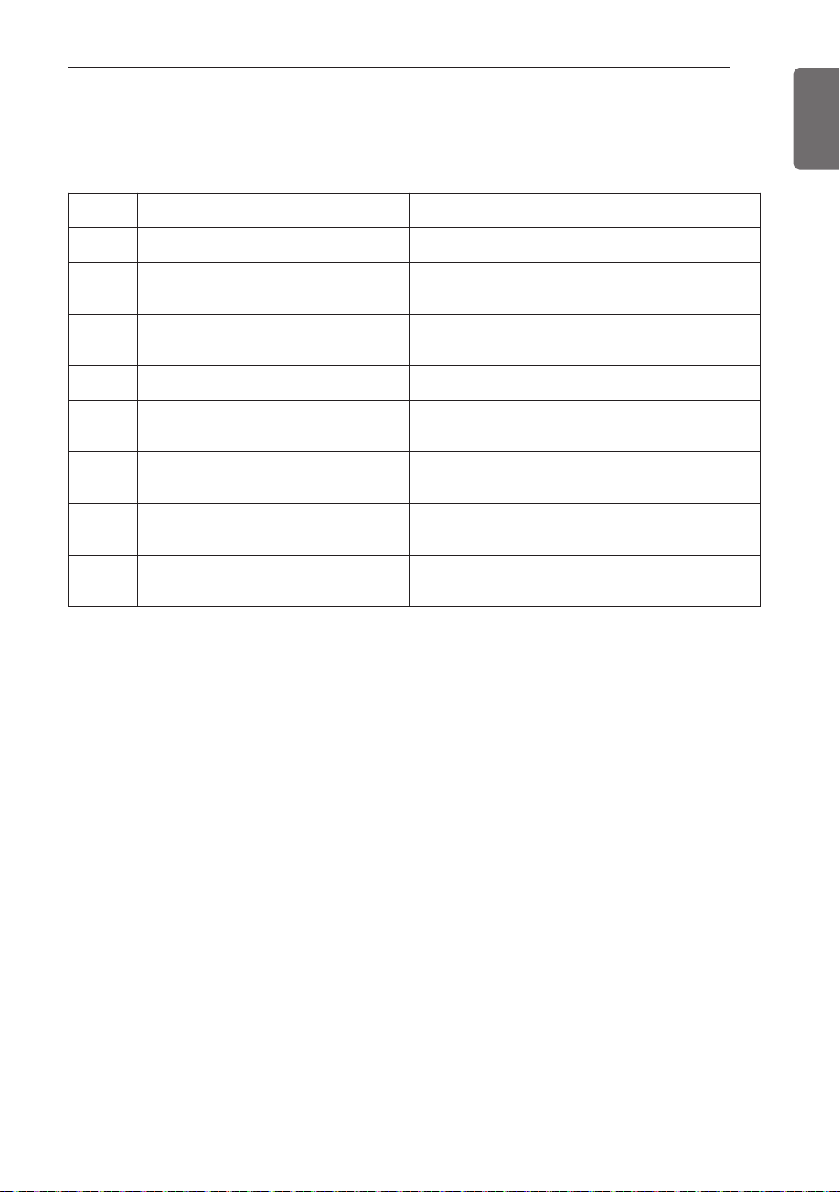
Indoor Unit Error
Code Title Cause of Error
1 Air temperature sensor of Indoor unit Air temperature sensor of indoor unit is open or short
2
Inlet pipe temperature Sensor of indoor
unit
Inlet pipe temperature sensor of indoor unit is open
or short
3
Communication error : wired remote
controller ↔ indoor unit
Failing to receive wired remote controller signal in
indoor unit PCB
4 Drain pump Malfunction of drain pump
5
Communication error : outdoor unit ↔
indoor unit
Failing to receive outdoor unit signal in indoor unit
PCB
6
Outlet pipe temperature sensor of indoor
unit
Outlet pipe temperature sensor of indoor unit is open
or short
9 Indoor EEPROM Error
In case when the serial number marked on EEPROM
of Indoor unit is 0 or FFFF
10 Abnormal fan motor operation
Disconnecting the fan motor connector / Failure of
indoor fan motor lock
36
SELF-DIAGNOSIS FUNCTION
ENGLISH
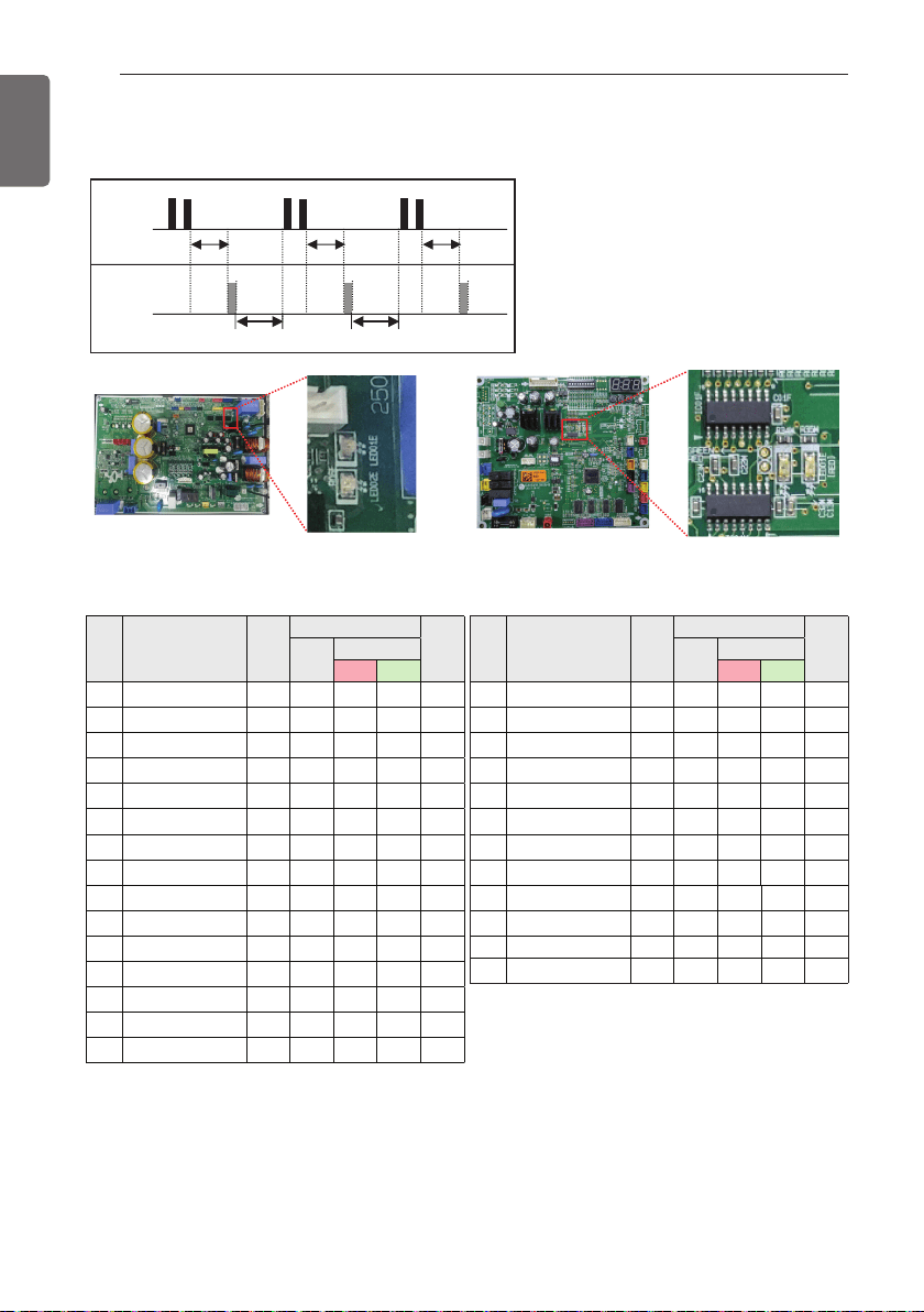
Outdoor Unit Error
1 Time 1 Time 1 Time
2 Times2 Times2 Times
1 second
2 seconds 2 seconds
1 second 1 second
LED01G
(RED)
LED02G
(GREEN)
Standard Inverter : 24 k Standard Inverter : 36 / 48 k
Code
Contents
Operation
State
Error Display
Count
Cable
Remote
Controller
Outdoor Device
Red LED
Green
LED
45
Cond. Pipe Sensor Error Stop CH45
Flashing 4
times
Flashing 5
times
1 time
Within 1h
46
Suction Pipe Sensor Error Stop CH46
Flashing 4
times
Flashing 6
times
1 time
Within 1h
47
D-Pipe Sensor Error (Constant-
rate Comp)
Stop CH47
Flashing 4
times
Flashing 7
times
1 time
Within 1h
51
Over-Capacity Connection
Error
Stop CH51
Flashing 5
times
Flashing 1
time
1 time
Within 1h
53
Communication Error between
Outdoor Device Indoor Device
Stop CH53
Flashing 5
times
Flashing 3
times
1 time
Within 1h
54
Open and Reverse Phase Error Stop CH54
Flashing 5
times
Flashing 4
times
10 times
Within 1h
60 EEPROM Check Sum Error Stop CH60
Flashing 6
times
-
1 time
Within 1h
61
Outdoor Device Pipe Overheat-
ing Error
Stop CH61
Flashing 6
times
Flashing 1
time
Infinite
restart
62 Heat-sink Overheating Error Stop CH62
Flashing 6
times
Flashing 2
times
Infinite
restart
65
Heat-sink Sensor Error Stop CH65
Flashing 6
times
Flashing 5
times
1 time
Within 1h
67 Outdoor BLDC Fan Lock Error Stop CH67
Flashing 6
times
Flashing 7
times
10 times
Within 1h
73
PSC/PFC Over-Current Error
(SW)
Stop CH73
Flashing 7
times
Flashing 3
times
10 times
Within 1h
Code Contents
Operation
State
Error Display
Count
Cable
Remote
Controller
Outdoor Device
Red LED
Green
LED
21
IPM Fault Error Stop CH21
Flashing 2
times
Flashing 1
time
10 times
Within 1h
22
CT 2 Error (Input of Over-
Current)
Stop CH22
Flashing 2
times
Flashing 2
times
Infinite
restart
23
DC Link Error (High/Low DC
Voltage)
Stop CH23
Flashing 2
times
Flashing 3
times
Infinite
restart
24
Pressure Switch High/Low
Pressure Fault
Stop
CH24
Flashing 2
times
Flashing 4
times
Infinite
restart
25
Input Frequency Detection
Failure
Stop CH25
Flashing 2
times
Flashing 5
times
1 time
Within 1h
26
DC Comp Position Detection
Error
Stop CH26
Flashing 2
times
Flashing 6
times
1 time
Within 1h
27
PSC/PFC Over-Current Error
(HW)
Stop CH27
Flashing 2
times
Flashing 7
times
10 times
Within 1h
29
Comp Phase Over-Current
Error
Stop CH29
Flashing 2
times
Flashing 9
times
10 times
Within 1h
32
D-Pipe Overheating Error (INV
Comp)
Stop CH32
Flashing 3
times
Flashing 2
times
Infinite
restart
33
D-Pipe Overheating Error
(Constant-rate Comp)
Stop CH33
Flashing 3
times
Flashing 3
times
Infinite
restart
35
Low Pressure Error of
Outdoor Unit
Stop CH35
Flashing 3
times
Flashing 5
times
38
Refrigerant Leakage Error Stop CH38
Flashing 3
times
Flashing 5
times
41
D-Pipe Sensor Error (INV
Comp)
Stop CH41
Flashing 4
times
Flashing 1
time
1 time
Within 1h
4 times
Within 3h
6 times
Within 1h
43 High pressure Sensor Error Stop CH43
Flashing 4
times
Flashing 3
time
1 time
Within 1h
44 Outdoor Inlet Sensor Error Stop CH44
Flashing 4
times
Flashing 4
times
1 time
Within 1h
DIP SWITCH SETTING FOR INDOOR UNIT
37
ENGLISH
Ceiling Cassette Type
Ceiling Concealed Duct Type
DIP SWITCH SETTING FOR INDOOR UNIT
Function Description Setting Off Setting On Default
SW3 Group Control
Selection of Master
or Slave
Master Slave Off
SW4
Dry Contact
Mode
Selection of Dry
Contact Mode
Wired/Wireless remote
controller
Selection of Manual or Auto
operation Mode
Auto Off
SW5 Installation
Fan continuous
operation
Continuous operation
Removal
Working Off
DIP Switch
38
DIP SWITCH SETTING FOR OUTDOOR UNIT
ENGLISH
WARNING
!
When you set the DIP switch, you should turn off the circuit breaker or shut the power
source of the product down.
CAUTION
!
• Unless the applicable DIP switch is set properly, the product may not work.
• If you want to set a specific function, request that the installer sets the DIP switch
appropriately during installation.
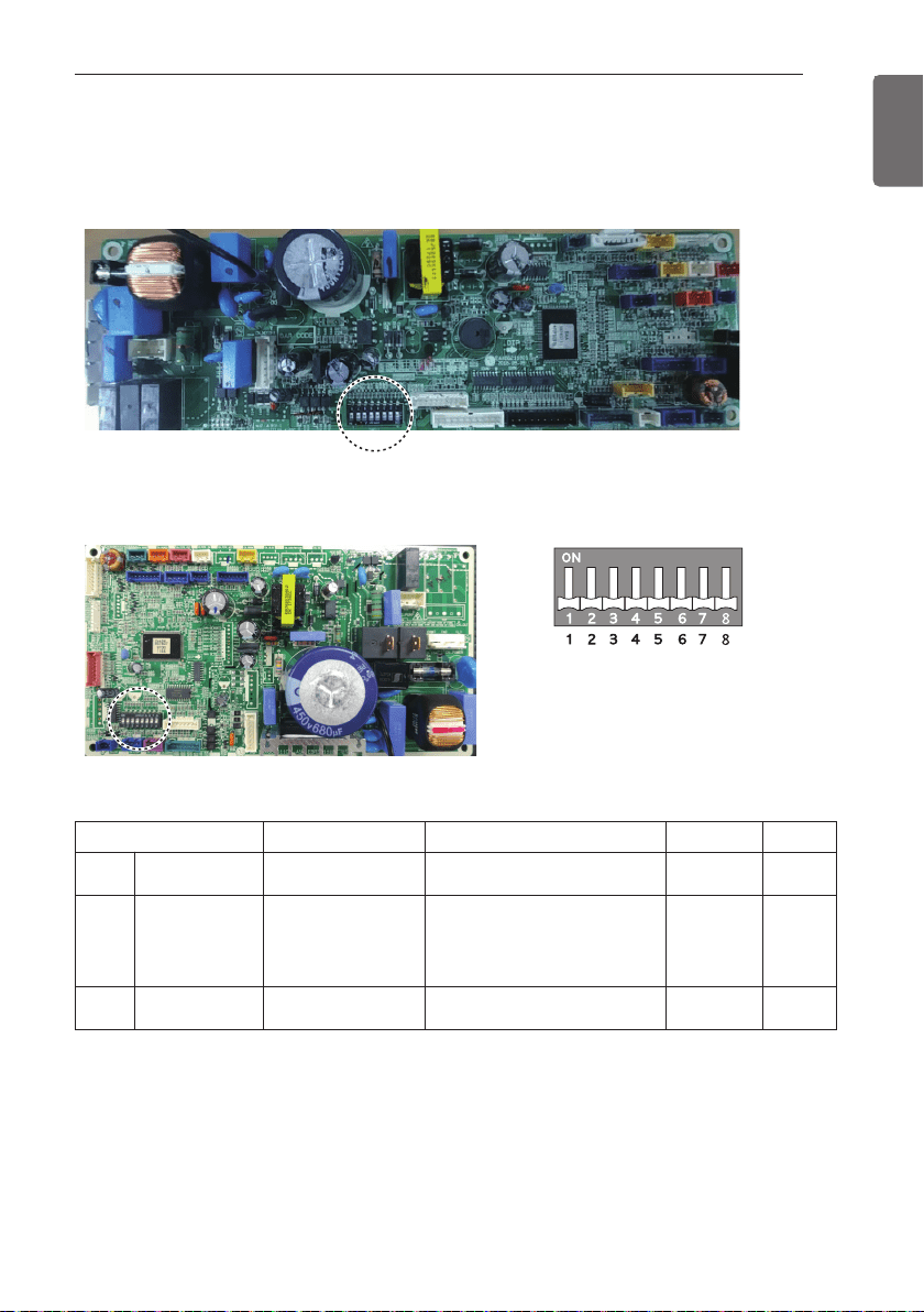
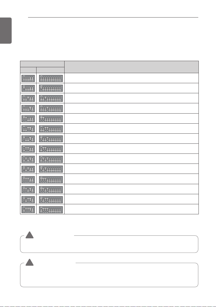
DIP Switch
Function
1 2
Normal Operation (No Function)
Pump Down
Saving Power Consumption (Step 1)
Saving Power Consumption (Step 2)
Mode Lock (Cooling)
Mode Lock (Heating)
Night Quiet Mode (Step 1)
Night Quiet Mode (Step 2)
Mode Lock (Cooling) + Night Quiet Mode (Step 1)
Mode Lock (Cooling) + Night Quiet Mode (Step 2)
Mode Lock (Cooling) + Saving Power Consumption (Step 1)
Mode Lock (Cooling) + Saving Power Consumption (Step 2)
Mode Lock (Heating) + Saving Power Consumption (Step 1)
Mode Lock (Heating) + Saving Power Consumption (Step 2)
1 : 24 k
2 : 36 / 48 k
DIP S/W Setting
If you set the DIP Switch when power is on, the change in setting is not applicable. The changing
setting is enabled only when Power is reset.
DIP SWITCH SETTING FOR OUTDOOR UNIT
DIP SWITCH SETTING FOR OUTDOOR UNIT
39
ENGLISH
WARNING
!
• When the green LED of PCB is on, compressor is going to be off because of low pressure.
• You should return the DIP Switch to operate normally after finishing the operation.
• Improper Pump down will lead to product turn off along with LED (green &red) off with in
20 minutes from the initial start.
• The actual product can be different from above contents depending upon model type.
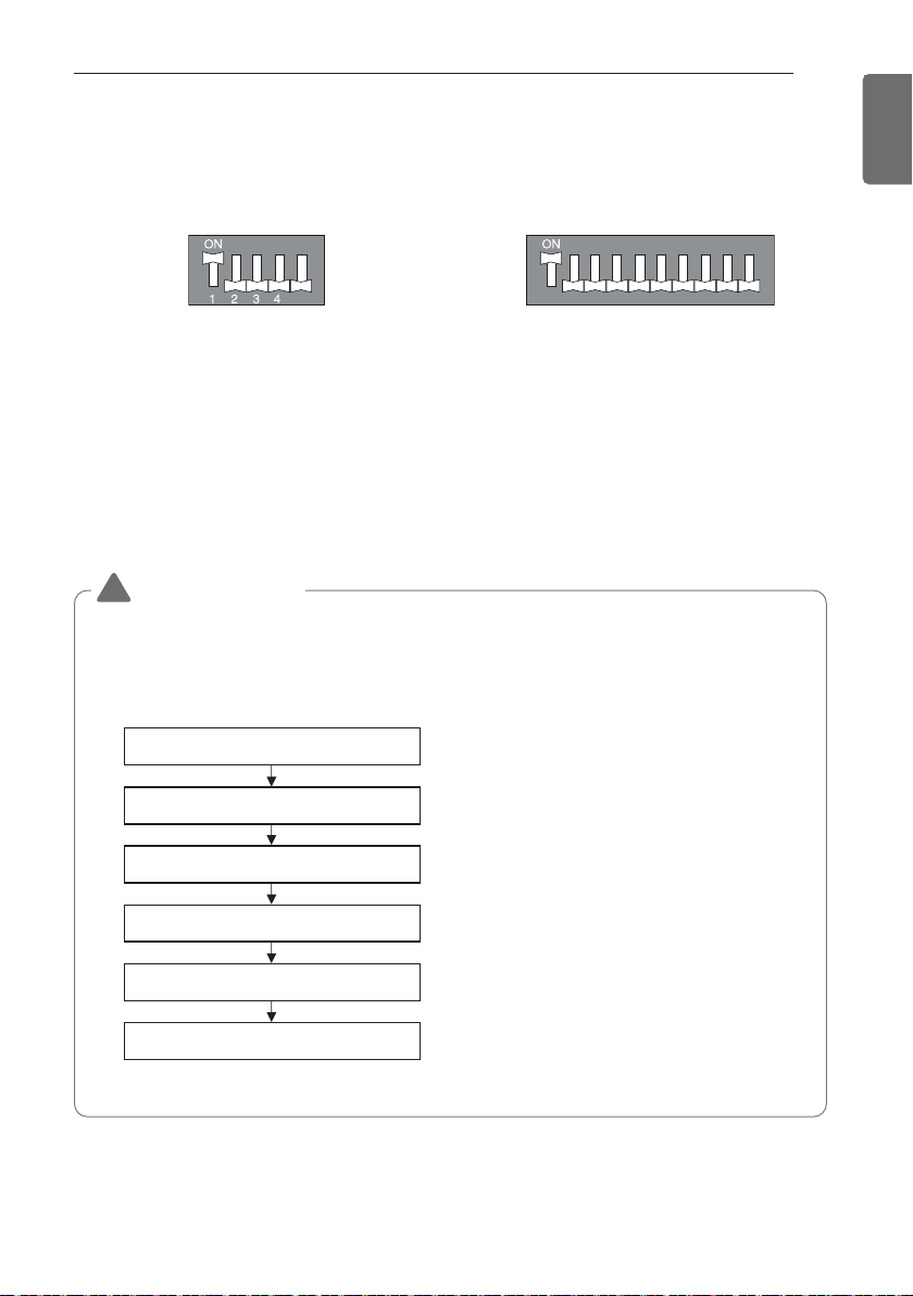
Pump Down DIP S/W Setting
Power on
(Red LED On, Green LED Off)
Comp on
(Red LED On, Green LED On)
Pump Down Start
(Red LED On, Green LED Off)
Liquid Valve Closed
Gas Valve Closed
Pump Down Complete
(Red LED Off, Green LED On)
Power off
(Red LED Off, Green LED On)
Pump Down
Setting Procedure
1 Set the DIP Switch as follow after shutting the power source down.
2 Reset the power.
3 Red LED and Green LED of PCB lights during work.
(The indoor unit is operated by force.)
4 If operation is done, Red LED will be turned off.
If operation is not done normally, Red LED will blink.
5 Close the Liquid valve only after green LED turned off (7 minutes from the start of the
machine). Then close the gas valve after Green LED on.
5
24 k
12345678910
36 / 48 k
40
DIP SWITCH SETTING FOR OUTDOOR UNIT
ENGLISH
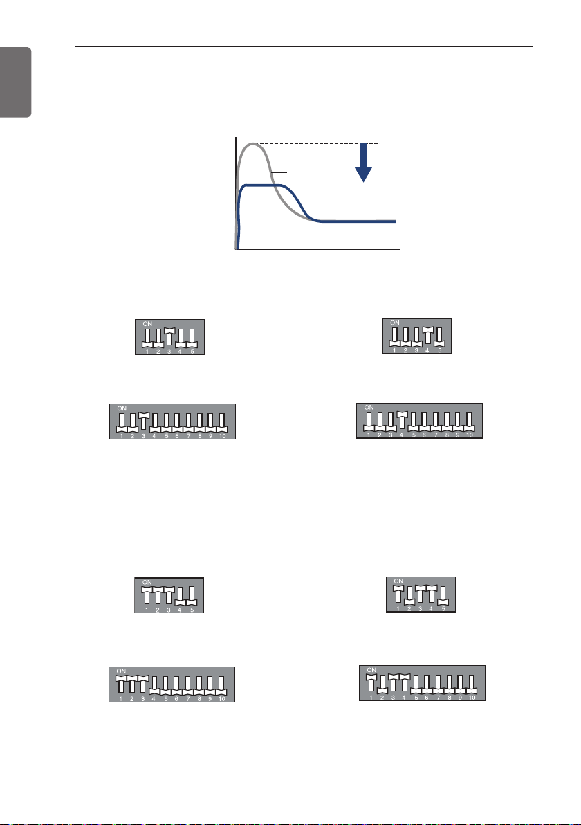
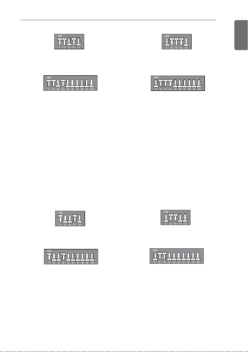
Saving Power Consumption
Saving Power Consumption operation is the function which enables efficient operation by
lowering the maximum power consumption value.
Setting Procedure
1 Set the DIP Switch as follow after shutting the power source down.
2 Reset the power.
24 k
36 / 48 k
Step 1
24 k
36 / 48 k
24 k
36 / 48 k
Step 2
Saving Power Consumption with Mode Lock.
Saving Power Consumption (step 1)
+ Mode Lock (Cooling)
24 k
36 / 48 k
Saving Power Consumption (step 1)
+ Mode Lock (Heating)
Power
consumption
and current
Nomal
Time
DIP SWITCH SETTING FOR OUTDOOR UNIT
41
ENGLISH
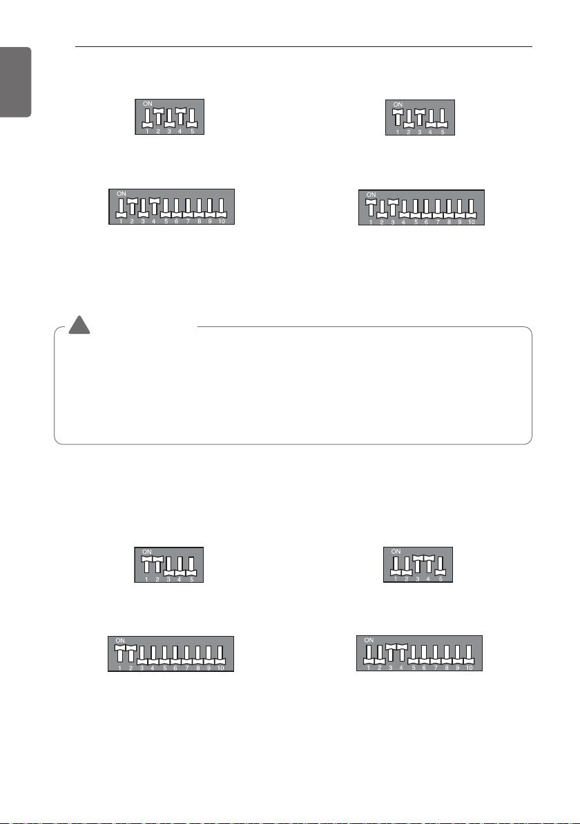
Night Quiet Mode
Night Quiet Mode operation lowers the noise level of the outdoor unit by changing the
Compressor’s frequency and fan speed. This function is operated all night long.
Setting Procedure
1 Set the DIP Switch as follow after shutting the power source down.
2 Reset the power.
h Noise level :Step 1 > Step 2
24 k
36 / 48 k
Saving Power Consumption (step 2)
+ Mode Lock (Cooling)
24 k
36 / 48 k
Saving Power Consumption (step 2)
+ Mode Lock (Heating)
24 k
36 / 48 k
Step 1
24 k
36 / 48 k
Step 2
42
DIP SWITCH SETTING FOR OUTDOOR UNIT
ENGLISH
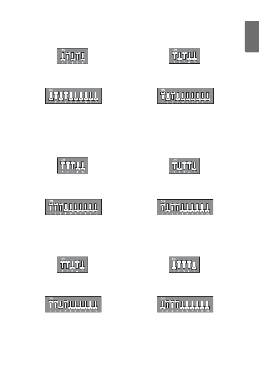
Night Quiet Mode with Mode Lock.
CAUTION
!
• If compressor’s frequency and fan speed are down, the cooling capacity may decrease
accordingly.
• This function is only available for Cooling Mode.
• If you want to stop the Night Quiet Mode, Change the DIP Switch.
• If operating indoor unit is set by the fan speed “Power”, Night Quiet Mode will be
stopped until fan speed “Power” is changed.
24 k
36 / 48 k
Mode Lock (Cooling)
+ Night Quiet Mode (step 1)
24 k
36 / 48 k
Mode Lock (Cooling)
+ Night Quiet Mode (step 2)
Mode Lock
Setting Procedure
1 Set the DIP Switch as follow after shutting the power source down.
2 Reset the power.
24 k
36 / 48 k
Only Cooling Mode
24 k
36 / 48 k
Only Heating Mode
DIP SWITCH SETTING FOR OUTDOOR UNIT
43
ENGLISH
Saving Power Consumption with Mode Lock.
Mode Lock with Night Quiet Mode
24 k
36 / 48 k
Mode Lock (Cooling)
+ Night Quiet Mode (step 1)
24 k
36 / 48 k
Mode Lock (Cooling)
+ Night Quiet Mode (step 2)
24 k
36 / 48 k
Mode Lock (Cooling) + Saving Power
Consumption (step 1)
24 k
36 / 48 k
Mode Lock (Heating) + Saving Power
Consumption (step 1)
24 k
36 / 48 k
Mode Lock (Cooling) + Saving Power
Consumption (step 2)
24 k
36 / 48 k
Mode Lock (Heating) + Saving Power
Consumption (step 2)

44
TIPS FOR SAVING ENERGY
ENGLISH
• Excessive cooling may be harmful to your health and may consume more electricity.
• Block sunlight with blinds or curtains while you are operating the air conditioner.
• Keep doors or windows closed while you are operating the air conditioner.
• Adjust the direction of the air flow vertically or horizontally to circulate indoor air.
• Speed up the fan to cool or warm indoor air quickly, in a short period of time.
• Open windows regularly for ventilation as the indoor air quality may deteriorate if the air
conditioner is used for many hours.
• Clean the air filter once every 2 weeks. Dust and impurities collected in the air filter may block the
air flow or weaken the cooling / dehumidifying functions.
For your records
Staple your receipt to this page in case you need it to prove the date of purchase or for warranty
purposes. Write the model number and the serial number here:
Model number :
Serial number :
You can find them labeled on the side of each unit.
Dealer’s name :
Date of purchase :
Here are some tips that will help you minimize the power consumption when you use the air
conditioner. You can use your air conditioner more efficiently by referring to the instructions
below:
TIPS FOR SAVING ENERGY

BEFORE USE
45
ENGLISH
About the system
This system of air conditioner can be used for heating/cooling applications.
Preparing for operation
• Contact an installation specialist for installation.
• Use a dedicated circuit.
Usage
• Being exposed to direct airflow for an extended period of time could be hazardous to your health. Do
not expose occupants, pets, or plants to direct airflow for extended periods of time.
• Due to the possibility of oxygen deficiency, ventilate the room when used together with stoves or
other heating devices.
• Do not use this air conditioner for non-specified special purposes (e.g. preserving precision devices,
food, pets, plants, and art objects). Such usage could damage the items.
Cleaning and maintenance
• Do not touch the metal parts of the unit when removing the filter. Injuries can occur when handling
sharp metal edges.
• Do not use water to clean inside the air conditioner. Exposure to water can destroy the insulation,
leading to possible electric shock.
• When cleaning the unit, first make sure that the power and breaker are turned off. The fan rotates at
a very high speed during operation. There is a possibility of injury if the unit’s power is accidentally
triggered on while cleaning inner parts of the unit.
Service
For repair and maintenance, contact your authorized service dealer.
Disposal
The unit uses hydrofluorocarbon. Contact your dealer when discarding this unit. It is required by law to
collect, transport and discard the refrigerant in accordance with the “hydrofluorocarbon collection and
destruction” regulations.
BEFORE USE
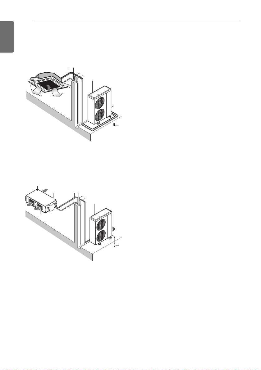
46
PRODUCT INTRODUCTION
ENGLISH
Name and function of parts (CEILING CASSETTE)
Name and function of parts (CEILING CONCEALED DUCT)
6
2
7
5
1
4
4
3
1: Indoor unit
2: Outdoor unit
3: Inlet air
4: Discharge air
5: Refrigerant piping, connection electric wire
6: Drain pipe
7: Ground wire
Wire to ground outdoor unit to prevent electrical
shocks.
4
2
7
3
4
Air intake
vents
1
Air outlet
vents
5
6
1: Indoor unit
2: Outdoor unit
3: Inlet air
4: Discharge air
5: Refrigerant piping, connection electric wire
6: Drain pipe
7: Ground wire
wire to ground outdoor unit to prevent electrical
shocks.
PRODUCT INTRODUCTION
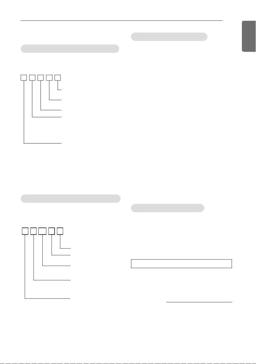
PRODUCT INTRODUCTION
47
ENGLISH
Model designation
- Product Name : Air conditioner
- Model Name :
- Additional Information : serial number is
refer to the barcode on the product.
- Max allowable pressure High side :
4.2 MPa / Low side : 2.4 MPa
- Refrigerant : R32
Product information – Outdoor Unit
UU24W R
R : R32 Refrigerant
Detailed product type
W : Heat-pump Inverter
Nominal Capacity
Ex) 24 000 Btu/h Class → ‘24’
Type
U : Outdoor units B : Duct
T : Cassette Q : Console
V : Floor-ceiling P : Floor standing
Model Type
U : Universal model
- Product Name : Air conditioner
- Model Name :
- Additional Information : serial number is
refer to the barcode on the product.
- Maximum allowable pressure High side :
4.2 MPa / Low side : 2.4 MPa
- Refrigerant : R32 / R410A
Product information – Indoor Unit
Detailed product type
R : R32 Refrigerant
Nominal Capacity
Ex) 24 000 Btu/h Class → ‘24’
Product Type
T : Ceiling Cassette Air Conditioner
B : Ceiling Concealed Duct Air Conditioner
V : Ceiling Suspended Air Conditioner
J : Wall Mounted Air Conditioner
Q : Console Air Conditioner
N : Indoor Unit
Connectable Outdoor Unit Type
U : Indoor units for universal outdoor units
TNU24R
The A-weighted sound pressure emitted by
this product is below 70 dB.
** The noise level can vary depending on the
site.
The figures quoted are emission level and are
not necessarily safe working levels.
Whilst there is a correlation between the
emission and exposure levels, this cannot be
used reliably to determine whether or not
further precautions are required.
Factor that influence the actual level of
exposure of the workforce include the
characteristics of the work room and the other
sources of noise, i.e. the number of
equipment and other adjacent processes and
the length of time for which an operator
exposed to the noise. Also, the permissible
exposure level can vary from country to
country.
This information, however, will enable the
user of the equipment to make a better
evaluation of the hazard and risk.
Airborne Noise Emission
Limiting concentration is the limit of Freon gas
concentration where immediate measures can
be taken without hurting human body when
refrigerant leaks in the air. The limiting
concentration shall be described in the unit of
kg/m
3
(Freon gas weight per unit air volume)
for facilitating calculation
Total amount of replenished
refrigerant in refrigerant facility (kg)
Capacity of smallest room where
indoor unit is installed (m
3
)
Refrigerant
concentration
(kg/m
3
)
=
Limiting concentration: 0.44 kg/m
3
(R410A)
Limiting concentration
n Calculate refrigerant concentration
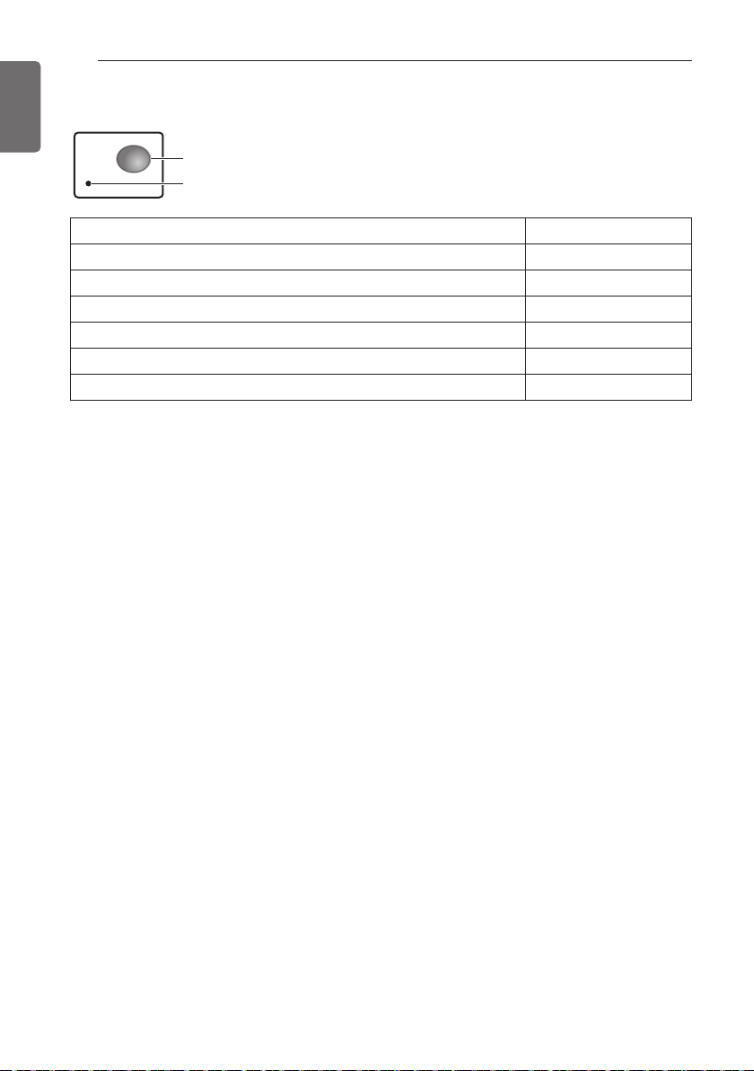
48
PRODUCT INTRODUCTION
ENGLISH
Lamp
Forced operation Button
Description Lamp Color
Cooling mode Green
Heating mode Green
Time to clean filter in cooling/heating Mode Yellowish Green
Time to clean filter when product is not operating Orange
Hot start or defrost mode before starting heating mode Green
When reservation set on Yellowish Green
Operation Indicator Lamp
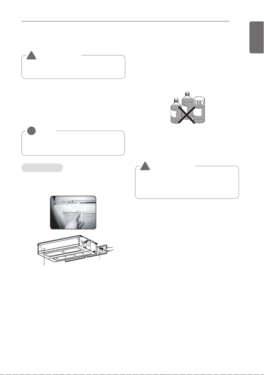
MAINTENANCE AND SERVICE
49
ENGLISH
Indoor Unit
Grille, Case and Remote Control
- Turn the system off before cleanining, To
clean, wipe with a soft, dry cloth. Do not use
bleach or abrasives.
The air filters behind the front grille should be
checked and cleaned once every 2 weeks or
more often if neccessary.
TU chassis : 4EA Rack
- Never use any of the followings:
Water hotter than 40 °C.
Could cause deformation and/or discoloration.
Volatile substances.
Could damage the surfaces of the air
conditioner.
1 Remove the Air filters.
- Take hold of the tab and pull slightly
forward to remove the filter.
2 Clean dirt from the air filter using a vacuum
cleaner or washing with water.
- If dirt is conspicuous, wash with a neutral
detergent in lukewarm water.
- If hot water (50 °C or more) is used, it may
be deformed.
3 After washing with water, dry well in the
shade.
- Do not expose the air filter to direct
sunlight or heat from a fire when drying it.
4 Install the air filter.
NOTE
!
Supply power must be disconnected before
cleaning the indoor unit.
Air Filters
Air outlet vent
Air filters
B
e
n
z
e
n
e
S
C
O
U
R
I
N
G
C
L
B
A
R
G
E
R
G
S
I
N
N
E
R
MAINTENANCE AND SERVICE
CAUTION
Before performing any maintenance, turn off the
main power to the system.
!
CAUTION
When the air filter is to be removed, do not touch
the metal parts of the indoor unit.
It may cause an injury.
!
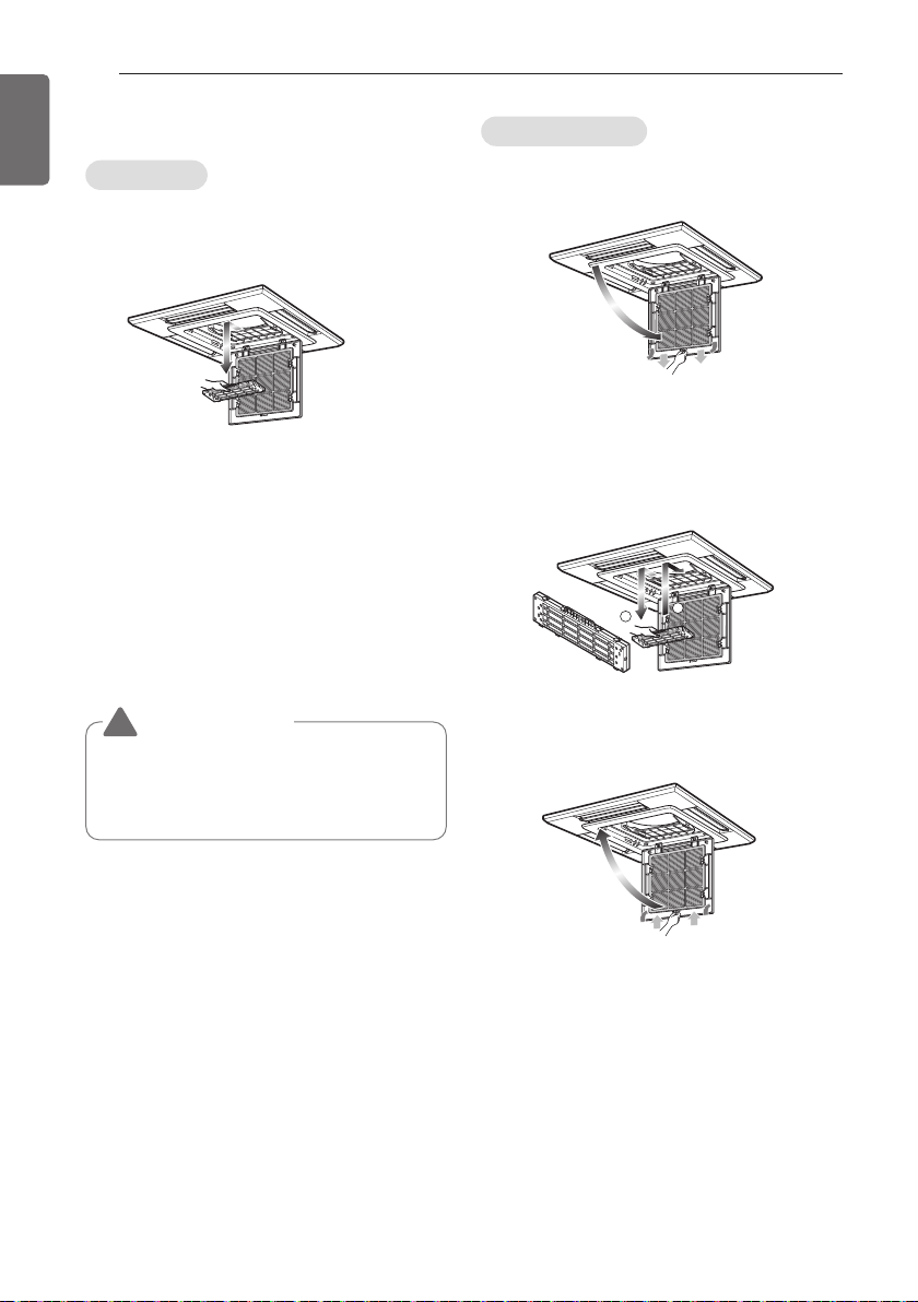
50
MAINTENANCE AND SERVICE
ENGLISH
Purifying filter(Optional)
The PLASMA filter behind the air filters should
be checked and cleaned once every 3 months or
more often if necessary.
1 After removing the air filters, pull slightly
forward to remove the PLASMA filter.
2 DIP the PLASMA filter into the water mixed
with neutral detergent, for 20~30 minutes.
3 Dry the PLASMA filter in the shade for a day
(Especially, the humidity must be removed
perfectly on this parts).
4 Note the cuts of electric discharge lines.
5 Re-install the PLASMA filter to the original
position.
- Recomended use period : About 2 years
1 Open front panel and remove air filter.
2 Remove air purifying filter.
3 Insert new air purifying filter.
4 Reinsert air filter and close front panel.
Cleaning
Replacement
1
2
CAUTION
Don’t touch this PLASMA Filter within 10 seconds
after opening the inlet grille, it may cause an
electric shock.
!

MAINTENANCE AND SERVICE
51
ENGLISH
Do not overcool the room.
This is not good for the health
and wastes electricity.
Keep blinds or curtains
closed.
Do not let direct sunshine enter
the room when the air
conditioner is in operation.
Keep the room temperature
uniform.
Adjust the vertical and
horizontal airflow direction to
ensure a uniform temperature in
the room.
Make sure that the doors
and windows are shut tight.
Avoid opening doors and
windows as much as possible to
keep the cool air in the room.
Clean the air filter regularly.
Blockages in the air filter reduce
the airflow and lower cooling
and dehumidifying effects.
Clean at least once every two
weeks.
Ventilate the room
occasionally.
Since windows are kept closed,
it is a good idea to open them
and ventilate the room now and
then.
When the air conditioner is not
going....
When air conditioner is not going to
be used for a long time.
1 Operate the air conditioner at the following
settings for 2 to 3 hours.
- Type of operation: Fan operation mode.
- This will dry out the internal mechanisms.
2 Turn off the breaker.
3 Remove the batteries from the Remote
Controller.
Helpful information
The air filters and your electiric bill.
If the air filters become clogged with dust, the
cooling capacity will drop, and 6 % of the
electricity used to operate the air conditioner will
be wasted.
When the air conditioner is to be
used again.
1 Clean the air filter and install it in the indoor
unit.
2 Check that the air inlet and outlet of the
indoor/outdoor unit are not blocked.
3 Check that the ground wire is connected
correctly. It may be connect to the indoor
unit side.
Operation Tips!
CAUTION
Turn off the breaker when the air conditioner is not
going to be used for a long time.
Dirt may collect and may cause a fire.
!
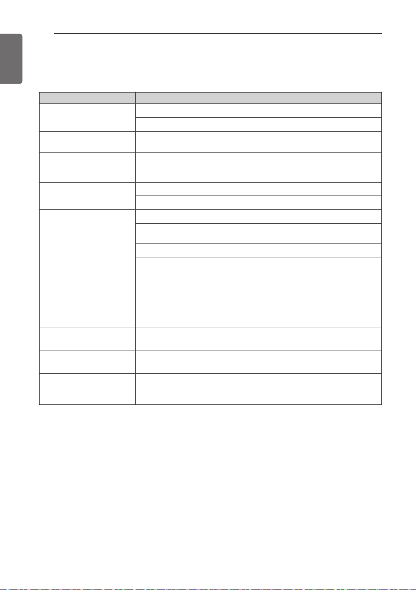
52
MAINTENANCE AND SERVICE
ENGLISH
Call the service immediately in the following situations
- Anything abnormal such as burning smell, loud noise etc. happen. Stop the unit and turn the breaker
off. Never try to repair by yourself or restart the system in such cases.
- Main power cord is too hot or damaged.
- Error code is generated by self diagnosis.
- Water leaks from indoor unit even if the humidity is low.
- Any switch, breaker (safety, earth) or fuse fails to work properly
User must carry routine checkup & cleaning to avoid unit’s poor performance.
In case of special situation, the job must be carried out by service person only.
Case Explanation
The air conditioner does
not operate.
• Have you made a mistake in timer operation?
• Has the fuse blown or has the circuit breaker been tripped?
The room has a peculiar
odor.
• Check that this is not a damp smell exuded by the walls, carpet, furniture
or cloth items in the room.
It seems that condensation
is leaking from the air
conditioner.
• Condensation occurs when the airflow from the air conditioner cools the
warm room air.
Air conditioner does not
operate for about 3
minutes when restart.
• This is the protector of the mechanism.
• Wait about three minutes and operation will begin.
Does not cool or heat
effectively.
• Is the air filter dirty? See air filter cleaning instructions.
• The room may have been very hot when the room air conditioner was first
turned on. Allow time for it to cool down.
• Has the setting temperature been set incorrectly?
• Are the indoor unit's air inlet or outlet vents obstructed?
The air conditioner
operation is noisy.
• For a noise that sounds like water flowing.
-This is the sound of freon flowing inside the air conditioner unit.
• For a noise that sounds like the compressed air releasing into atmosphere.
-This is the sound of the dehumidifying water being processed inside the
air conditioning unit.
Crack sound is heard.
• This sound is generated by the expansion/contraction of the inlet grille,
etc. due to changes of temperature.
Remote control display is
faint, or no display at all.
• Has the circuit breaker been tripped?
• Are the batteries inserted in the opposite (+) and (-) directions?
The error code is occurred
after lightning struck
• This product has been applied to the over current protection circuit.
Error can occur, but it is normal behavior.
After few minutes, It will operate normally.
Troubleshooting Tips! Save time and money!
Check the following points before requesting repairs or service.... If the malfunction persist, please
contact your dealer.

MAINTENANCE AND SERVICE
53
ENGLISH

54
ENGLISH

55
ENGLISH