Loading ...
Loading ...
Loading ...
Note: we recommend you keep the transit bracket,
braces and screws to immobilise the machine for future
transit.
The Manufacturers will not be responsible for any
possible damage to the machine caused by not
following the rules relating to releasing the mechanism.
The user is responsible for all costs of installation.
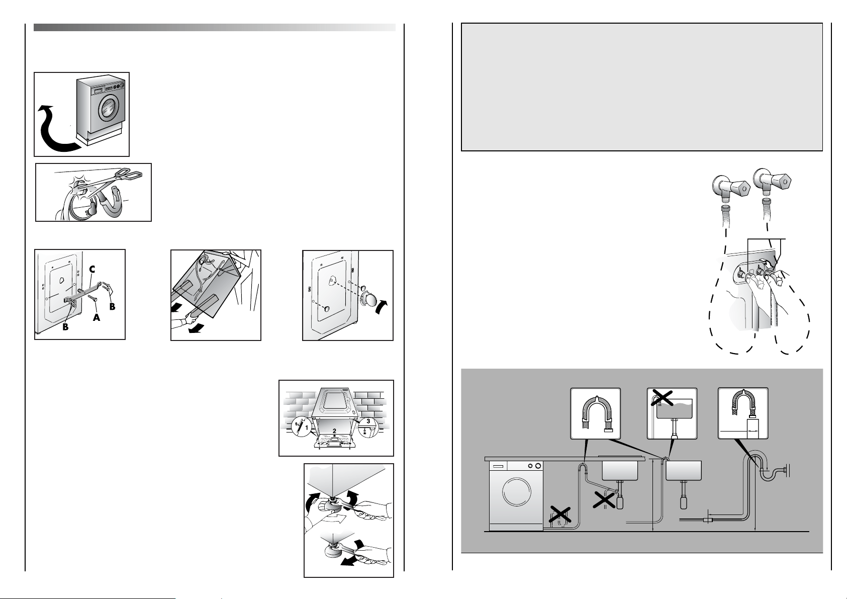
Water connection
The appliance must be connected to the water mains
using new hose-sets.
The old hose-sets should not be reused.
Your machine may either be plumbed in or connected
to existing taps, using a tap adaptor with a 3/4 B.S.P.
threaded end connection. The water supply hoses to
be found inside the drum are terminated in two
different ways. One end which has a 90° elbow is to
be connected to the appliance water connection E
while the straight end is to be connected to the
domestic supply tap. The hose with the white collar
should be connected to the cold tap, and the hose
with the red collar to the hot tap. The appliance is not
suitable for use with mixer taps.
min 50 cm
max 85 cm
+2,6 mt max
max 100 cm
min 4 cm
E
HOT
WATER
COLD
WATER
27
SETTING UP + INSTALLATION
Remove the polystyrene base and place the machine near
its permanent position (diagram 1).
Carefully cut through the hose retaining clip at the rear of
the appliance (diagram 2).
Unscrew the central bolt (A); unscrew the 4 lateral screws
(B) and remove the cross piece (C) (diagram 3).
Unscrew the two rods D and remove them. Two plastic
spacers will fall inside the machine.
Lean the machine forward, remove the mentioned plastic
spacers and remove the plastic bags containing the two
polystyrene blocks at the sides, pulling downwards (diagram 4).
Stop the holes using the plugs that you will find inside the
bag containing the instruction booklet (diagram 5).
WARNING:
DO NOT LEAVE THE PACKAGING WITHIN REACH OF CHILDREN AS IT IS A POTENTIAL
SOURCE OF DANGER.
Apply the insulation sheet of corrugated material to the base
as shown.
Level the machine by means of the front feet.
a) Turn the nut clockwise to release the screw adjuster on the foot.
b) Rotate the foot to raise or lower it until it stands
firmly on the ground.
c) Lock the foot in position by turning the nut
anti-clockwise until it comes up against the bottom of the machine.
D
A
B
C
1
2
34 5
26
Loading ...
Loading ...
Loading ...