
www.lg.com
OWNER'S MANUAL
LG CLOUD V SERIES BOX
CBV42
Please read the safety information carefully before using the product.
LG Cloud V Series Box Model List
English

2
ENG
English
Table of Contents
Table of Contents
3 ASSEMBLING AND
PREPARING
3 Unpacking
4 Parts and Buttons
5 Product Installation
5 - Using in Horizontal Position
5 - Using in Vertical Position
5 - Mounting on the Back of the Monitor
6 CONNECTING LAN/
PERIPHERALS
6 - LAN Connection
6 - DisplayPort Connection
7 - Extended Monitor Connection
7 - Peripheral device connection
9 TROUBLESHOOTING
10 SPECIFICATIONS
10 Power Indicator
11 USING CLOUD SOLUTION
3
ENG
English
ASSEMBLING AND PREPARING
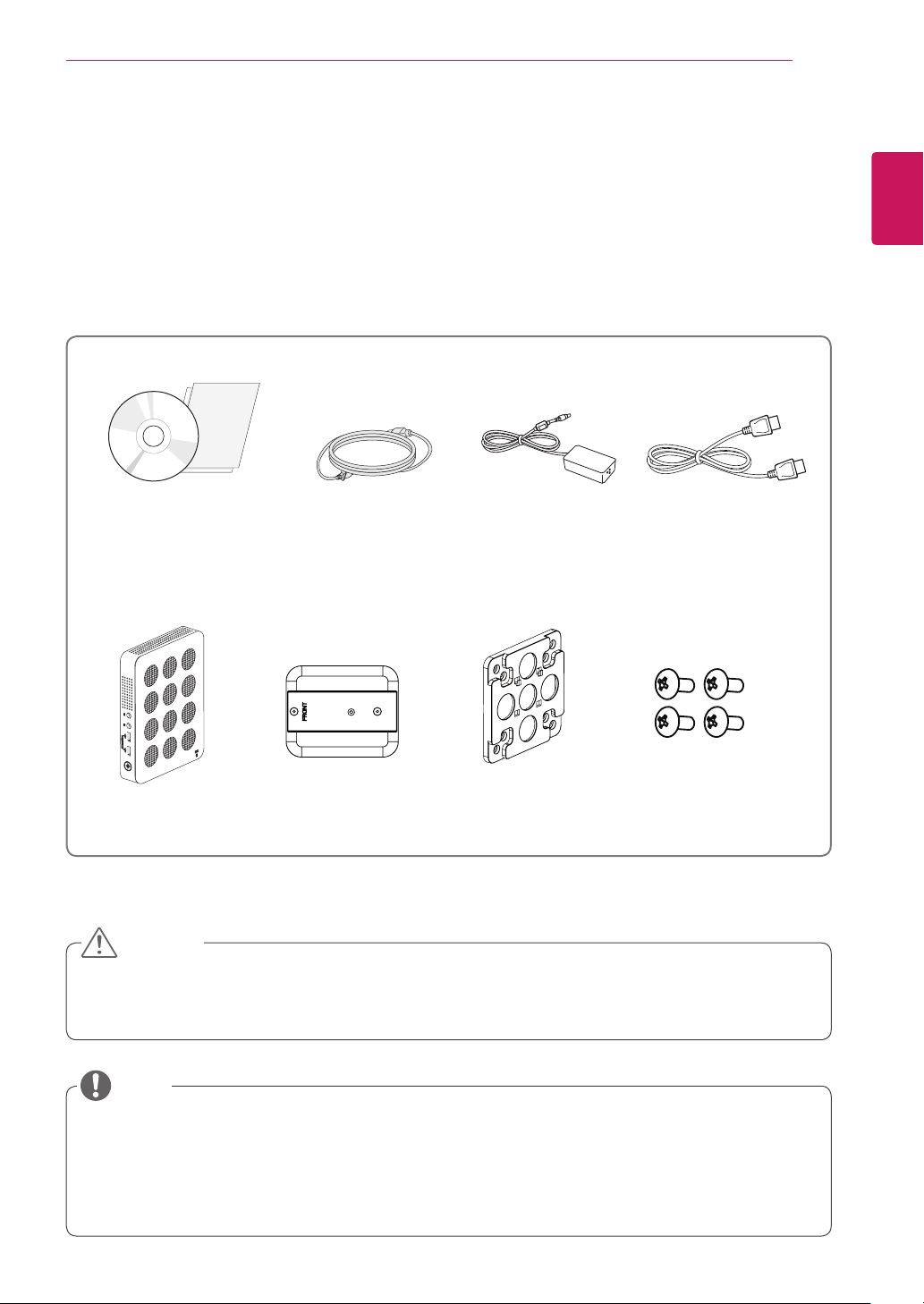
Main Unit Stand Base Mount Bracket 4 Screws
Power CordCD / Card
DisplayPort Cable
AC/DC Adapter
ASSEMBLING AND PREPARING
Unpacking
Please check whether all the components are included in the box before using the product. If there are
missing components, contact the retail store where you purchased the product. Note that the product and
components may look different from those shown here.
y
Only use an approved LG power adapter.
y
Damage caused by other power adapters is not covered by warranty.
y
Note that the components may look different from those shown here.
y
Without prior notice, all information and specifications in this manual are subject to change to improve
the performance of the product.
y
To purchase optional accessories, visit an electronics store or online shopping site or contact the retail
store where you purchased the product.
CAUTION
NOTE
4
ENG
English
ASSEMBLING AND PREPARING
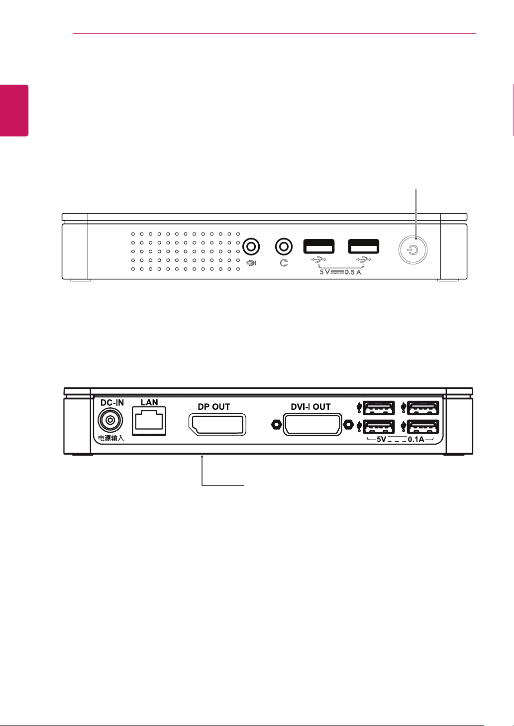
Parts and Buttons
Power Indicator &
Power Button
y
On: Power On
y
Off: Power Off
Input Connectors
Front Side
Rear Side
5
ENG
English
ASSEMBLING AND PREPARING
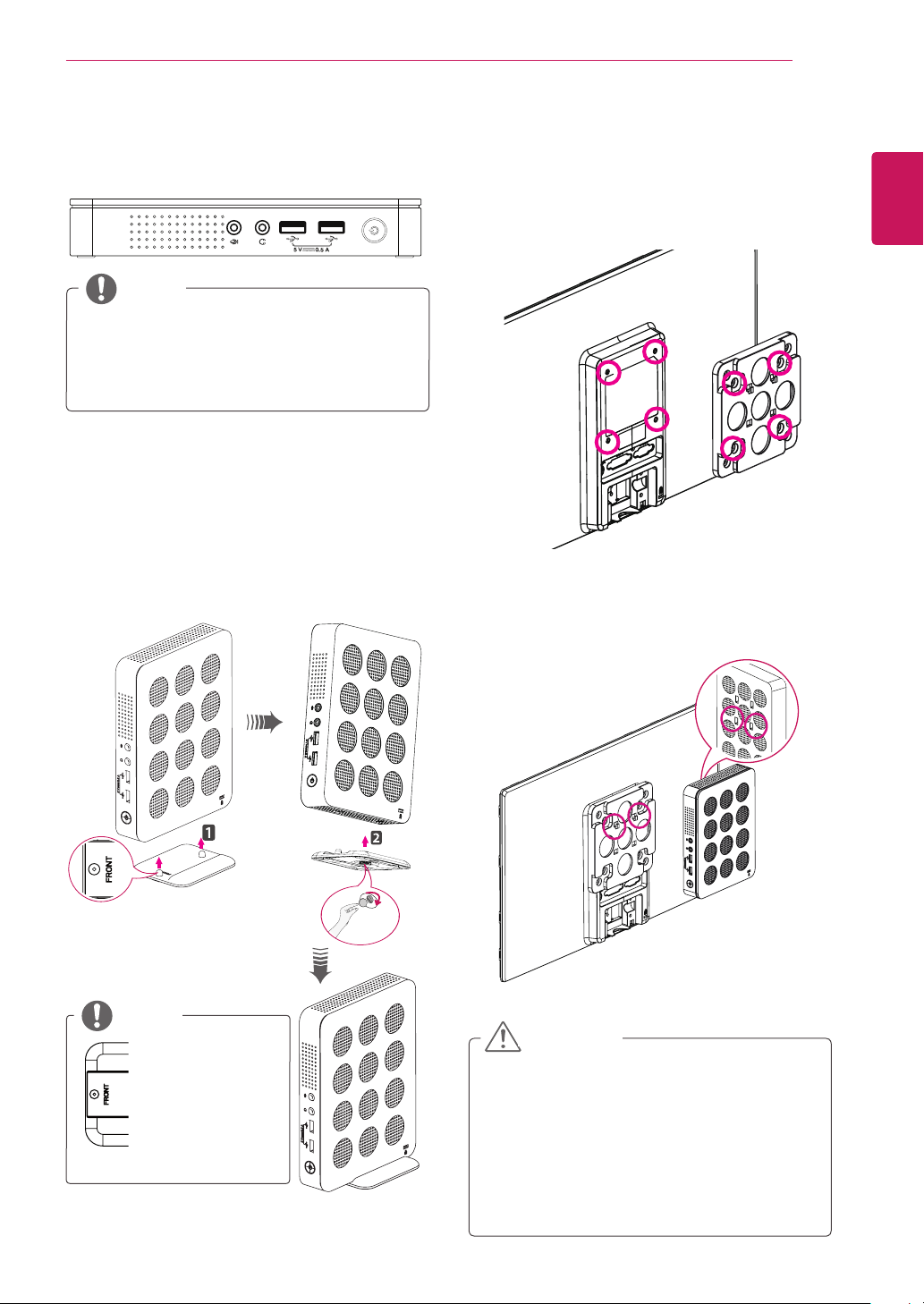
Product Installation
Using in Horizontal Position
Using in Vertical Position
1
Firmly attach the stand on the bottom of the
product as illustrated below.
2
Using a coin, turn the screw clockwise to
secure the stand base.
Mounting on the Back of the
Monitor
1
Fix the mount bracket on the back of the
monitor with 4 screws as illustrated below.
2
Put the product on the two latches as illustrated
below.
Assemble the product by aligning the below
two holes out of 4 holes on the product.
y
Attach the stand
base to the
stand hinge with
its front part fac-
ing forward.
y
If this product is used with upside down, it
may not work properly.
y
Use the product with the Kensington lock
facing upward.
NOTE
y
The product may not be mounted on some
monitors with mount bracket.
- In this case, use the product in horizontal
or vertical position.
y
When connecting the peripherals after
mounting the product on the monitor, be
sure to hold the product.
CAUTION
NOTE
6
ENG
English
Connecting LAN/Peripherals
CONNECTING LAN/PERIPHERALS
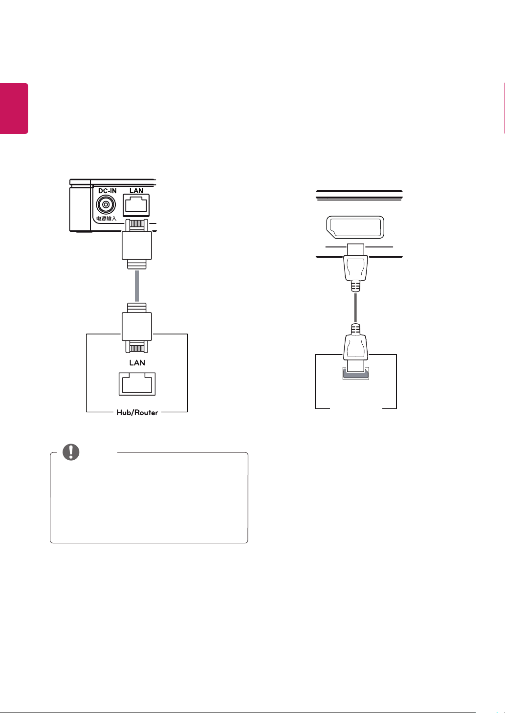
DisplayPort Connection
Transmits digital video signals to the monitor. Con-
nect the product using the DisplayPort cable as
illustrated below.
y
The LAN cable is sold separately.
y
The following LAN cable type can be used:
Standard: IEEE 802.3 ETHERNET
y
Connect the LAN cable and the peripheral de-
vices to use the CITRIX cloud monitor.
DP OUT
DP IN
MONITOR 1
DP OUT
DP IN
MONITOR 1
NOTE
LAN Connection
Connect the router or switch to the monitor using a
LAN cable as illustrated below.
7
ENG
English
Connecting LAN/Peripherals
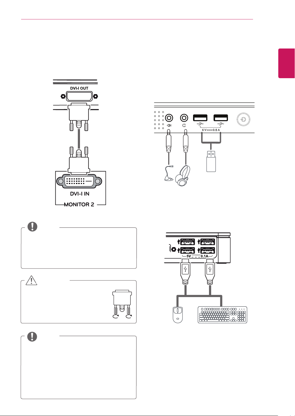
y
Connect the input signal cable
and turn in the direction of the
arrow. To prevent disconnection
secure the cable tightly.
y
When connecting the power cord to the
outlet, use a grounded (3-hole) multi-socket
or a grounded power outlet.
y
DVI cable is not included in the basic com-
ponents. Use the DVI cable provided with
the monitor or the standard DVI cable.
y
If the main/sub screen was changed after
extended monitor was connected, the main/
sub can be changed in Setup.
Extended Monitor Connection
Transmits digital video signals to the monitor. Con-
nect the product using the DVI cable as illustrated
below.
DP OUT
DP IN
MONITOR 1
DP OUT
DP IN
MONITOR 1
DP OUT
DP IN
MONITOR 1
Peripheral device connection
Connect peripheral devices to the monitor using
USB, microphone and headphone ports.
Front Side
Rear Side
CAUTION
NOTE
NOTE
8
ENG
English
Connecting LAN/Peripherals
y
The cloud server settings may affect the perfor-
mance of the headphones, earphones or speak-
ers depending on the connected cloud server.
y
The cloud server settings may affect the
functions or speed of the specific USB stor-
age device depending on the connected
cloud server.
y
Peripheral devices are sold separately.
y
The USB ports can be used to connect the
keyboard, mouse, and other USB devices.
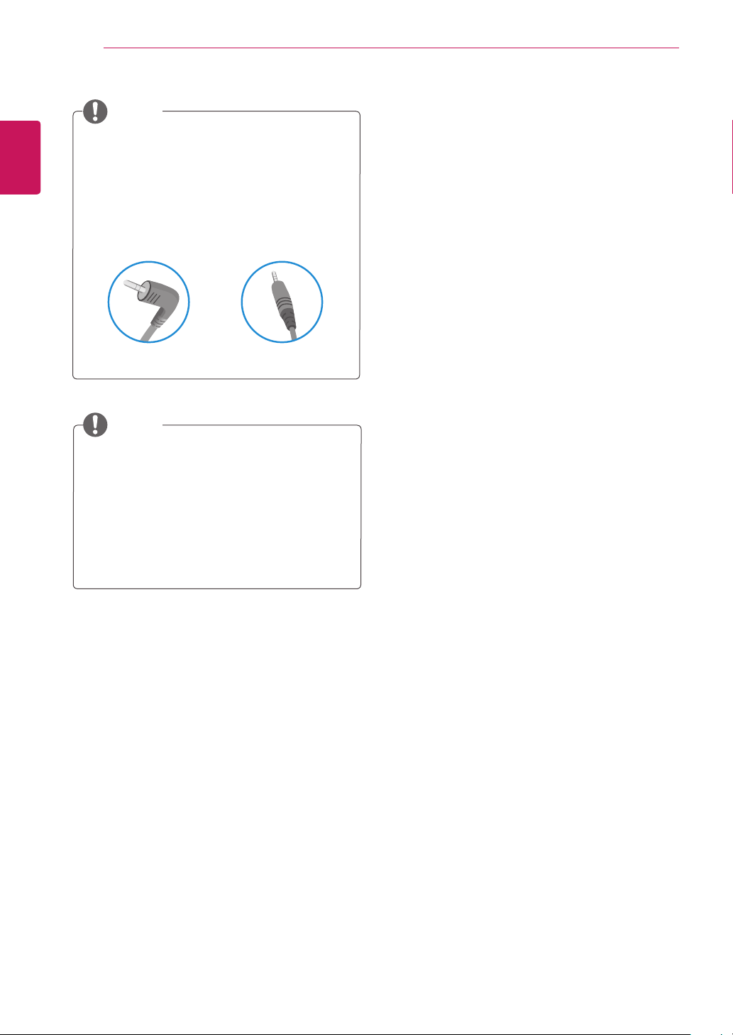
y
For an angle plug earphone/microphone, it is
difficult connect it with a peripheral device, so
use a straight type.
Angle Type Straight Type
NOTE
NOTE
9
ENG
English
TROUBLESHOOTING
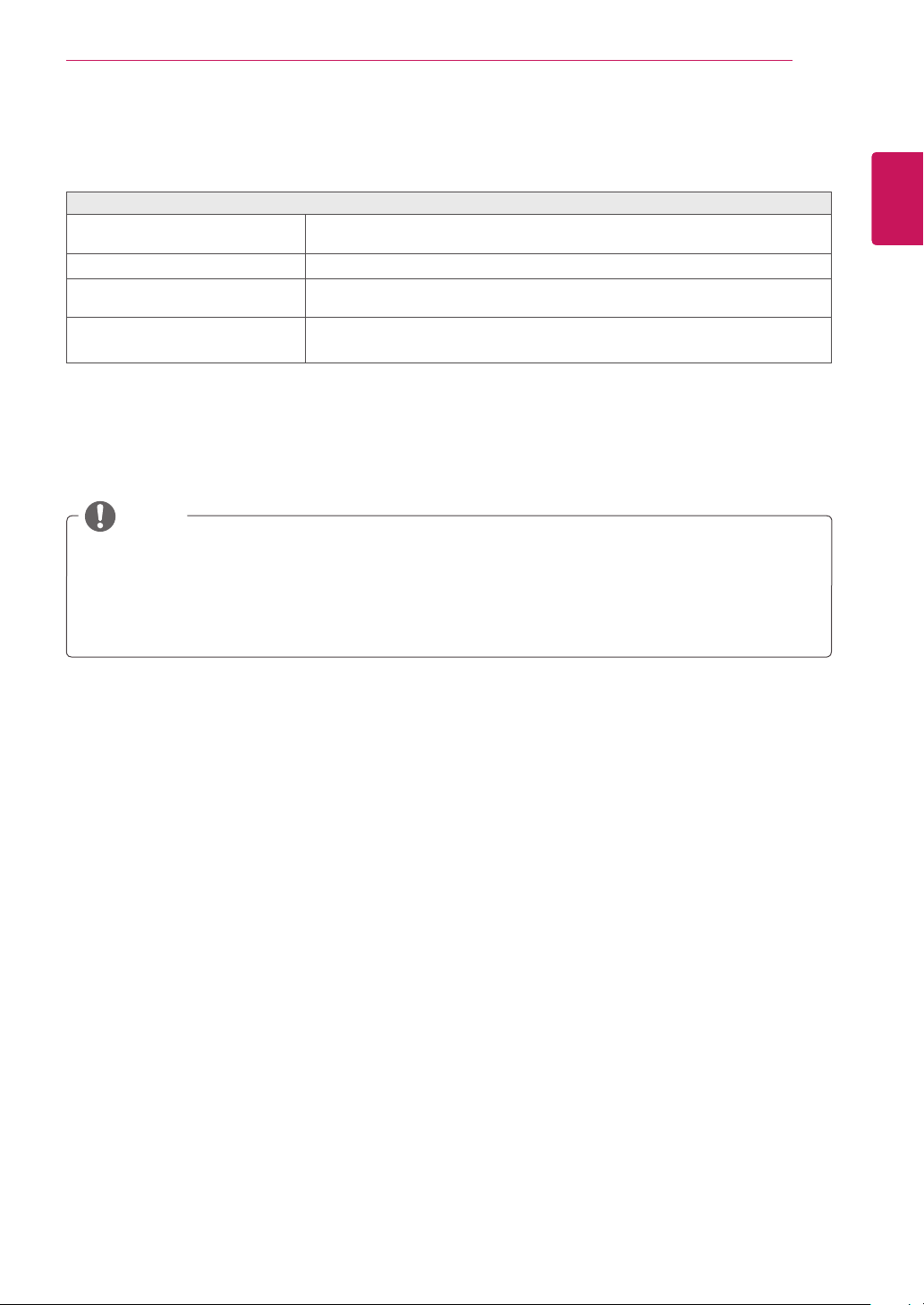
TROUBLESHOOTING
Nothing is displayed on the screen
Is the power adapter of the Box
plugged in ?
y
Check if the power cord is correctly plugged in to the power outlet.
Is the power indicator on?
y
Check the power indicator.
Is the power indicator displaying as
red?
y
Adjust the brightness and the contrast of the connected monitor.
Are the BOX and the monitor con-
nected with the signal cable?
y
Check whether the monitor and the Box are properly connected to DVI
cable or DisplayPort cable.
y
This box type product is used by connecting the monitor.
y
If the monitor does not work normally, the screen may not be displayed correctly.
NOTE
10
ENG
English
SPECIFICATIONS
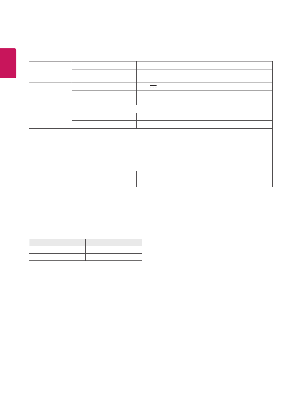
SPECIFICATIONS
Supported Dis-
play Resolution
Maximum Resolution 1920 x 1200 @ 60 Hz
Recommended Resolution 1920 x 1200 @ 60 Hz
Power Voltage 19 V
1.2 A
Power consumption (Typ.)
(Cloud)
Cloud Mode 6 W
Off Mode ≤ 0.5 W
Dimension Dimensions (Width x Height x Depth)
With stand 70.3 mm x 189.3 mm x 143.6 mm
Without Stand 185 mm x 30.5 mm x 143.6 mm
Weight (Without
Packaging)
0.6 kg
AC/DC adapter Type ADS-40SG-19-3 19025G, manufactured by SHENZHEN HONOR ELECTRONIC
Or Type LCAP21, manufactured by LIEN CHANG ELECTRONIC ENTERPRISE
Or Type PSAB-L203A, manufactured by LG Innotek Co.,Ltd
Output: 19 V
1.3 A
Environmental
Conditions
Operating Condition Temperature: 10°C to 35°C; Humidity: 10% to 80%
Storing Condition Temperature: -20°C to 60°C; Humidity: 5% to 90%
The specifications are subject to change without notice.
Power Indicator
Mode LED Color
On Mode Red
Off Mode Off
11
ENG
English
Using CLOUD Solution
USING CLOUD SOLUTION
If the network is connected and IP is being ac-
quired, the message "Network connection detect-
ed. Acquiring IP address …" is displayed on the
Connection screen. Figure 2-3 shows the message
displayed when the network is ready and the IP is
being acquired.
The below is the Connection screen displayed
when network is completely ready.
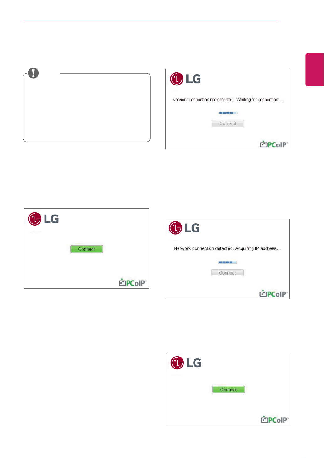
If the network is not properly connected (e.g., dur-
ing portal boot up), or connection is being created,
the "Network connection lost. Waiting for connec-
tion …" message is displayed on the Connection
screen.
Figure 2-2 shows the message displayed when the
network is not ready.
<Figure 2-1: OSD Connect Screen>
<Figure 2-3 Acquiring the IP after Network Con-
nected>
Connect Screen
The Connect screen is shown during start-up,
except when the portal has been configured for a
managed start-up or auto-reconnect. The logo dis-
played above the Connect button can be changed
by uploading a replacement image via the admin
interface.
<Figure 2-2: Network Not Ready>
NOTE
y
Menus and functions in CLOUD mode may
be slightly different depending on the firm-
ware version.You can download the user
manual for each version from the Teradici
homepage: http://www.teradici.com
y
To check the firmware version, see page
<28>.
<Figure 2-4: Network Ready>
12
ENG
English
Using CLOUD Solution
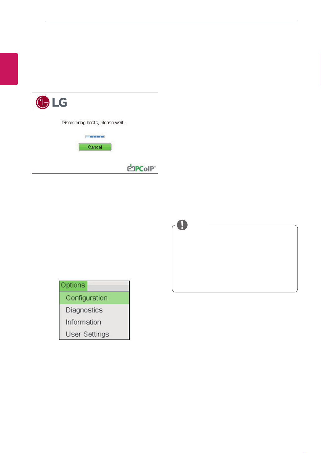
<Figure 2-5: OSD Connect Screen (Connecting)>
OSD Options Menu
Selecting the Options menu will produce a list of
selections. The OSD Options menu contains:
y
Configuration
y
Diagnostics
y
Information
y
User Settings
Selecting one of the options will produce a settings
window.
y
Some PCoIP devices have their password
protection disabled and can be logged into
the management web page or access the
OSD parameters without a password. The
login page and the OSD's password protec-
tion can be enabled in the PCoIP manage-
ment console.
NOTE
If you select the Connect button, the connection
session is started. When the connection is pend-
ing, the "Discovering hosts, please wait…" mes-
sage is displayed on the OSD local GUI.When the
connection is established, the OSD local GUI will
disappear and be replaced by the session image.
<Figure 2-6: OSD Options Menu>
Configuration Window
In the Configuration window, the administrator can
access the window tabs that contain the settings to
configure and manage the portal environment.
The Configuration window has the following tabs:
y
Network
y
Label
y
Connection Management
y
Discovery
y
Session
y
RDP
y
Language
y
OSD
y
Reset
y
Display
y
VMware View
Each tab contains OK, Cancel and Apply buttons
to allow the administrator to apply or cancel the
modified settings as well as the Advanced button
for advanced settings.
13
ENG
English
Using CLOUD Solution
y
In order to utilize the FQDN feature, a DNS
server, configured properly with DHCP option
81, must be used.
y
Gateway
The Gateway field contains the gateway IP ad-
dress of the device. If DHCP is disabled, this field
is required. If DHCP is enabled, this field cannot be
edited.
y
Primary DNS Server
The Primary DNS Server field contains the primary
DNS IP address of the device. This field is option-
al. If DHCP is enabled, this field cannot be edited.
y
Secondary DNS Server
The Secondary DNS Server field contains the sec-
ondary DNS IP address of the device. This field is
optional. If the DHCP is enabled, this field cannot
be edited.
y
Domain Name
The Domain Name field contains the domain name
used, e.g. "domain local". This field is optional. It speci-
fies on which domain the host or portal operates.
y
FQDN
The FQDN field represents the Fully Qualified Do-
main Name of the host or portal. The default value is
PCoIP-host-MAC or PCoIP-portal-MAC, where MAC
is the MAC address of the host or portal. If there is
a domain name, it will be added to the FQDN in the
format of PCoIP-host-MAC.domain.local
y
Ethernet Mode
The Ethernet Mode field specifies the portal's Eth-
ernet mode.
The available options are as follows.
y
Auto
y
100 Mbps Full-Duplex
y
10 Mbps Full-Duplex
If another network device (for example, a switch) is
configured to operate under 10 Mbps Full-Duplex,
100Mbps Full-Duplex or 1GbpsFull-Duplex, the
administrator should always set the Ethernet Mode
field to Auto; and if the device is to operate under
only one speed out of multiple settings, select ei-
ther 10 Mbps Full-Duplex or 100 Mbps Full-Duplex.
NOTE
y
The network parameters can also be con-
figured using the Webpage Administration
Interface.
NOTE
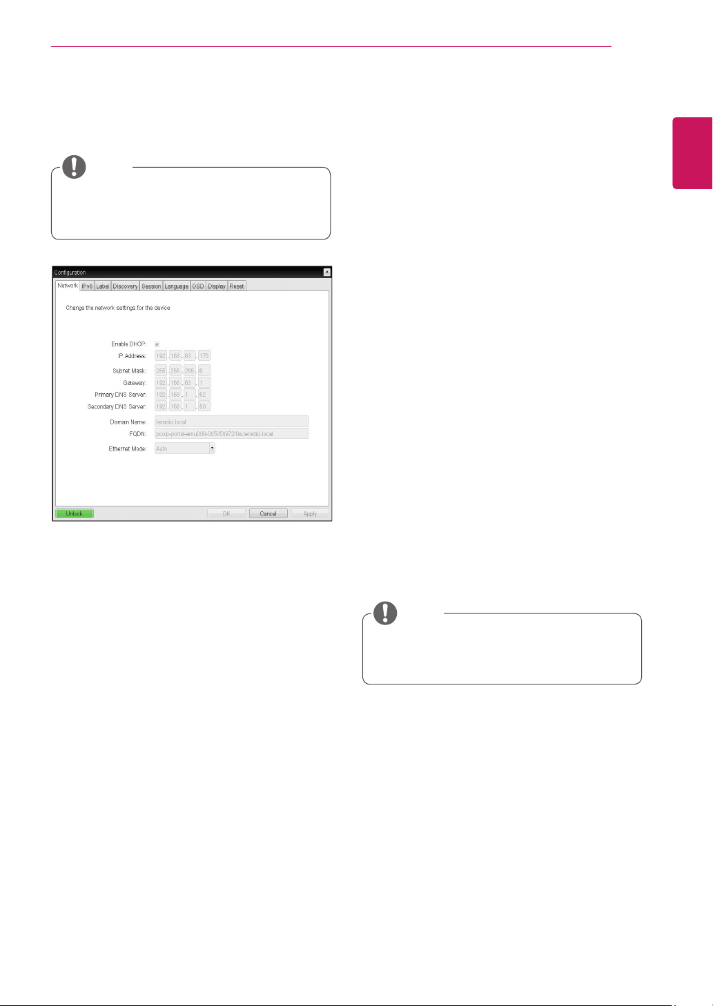
Network Tab
The Network tab allows the administrator to config-
ure the portal network parameters.
Figure 2-7. Network Configuration
y
Enable DHCP
If the Enable DHCP option is selected, a device will
be connected to the DHCP server. that allocates
the IP address, subnet mask, gateway IP address,
and DNS server. If this option is disabled, the
above parameters must be configured manually.
y
IP Address
The IP Address field contains the IP address of the
device. If DHCP is disabled, this field is required.
If DHCP is enabled, this field cannot be edited.
This field must contain the correct IP address. If an
incorrect IP address is provided, an OSD message
is displayed prompting the administrator to provide
the correct the IP address.
y
Subnet Mask
The Subnet Mask field contains the subnet mask
of the device. If DHCP is disabled, this field is
required. If DHCP is enabled, this field cannot be
edited. This field must have the correct subnet
mask. If an incorrect subnet mask is provided, an
OSD message is displayed prompting the adminis-
trator to provide the correct the subnet mask.
14
ENG
English
Using CLOUD Solution
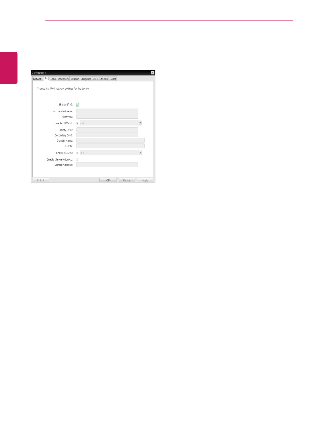
<Figure 2-8: IPv6 Configuration>
<IPv6> Tab
The IPv6 tab is used when the portal is connected
to the network configured with the IP v6.
y
Enable IPv6
If you select Enable IPv6, the portal in use can be
connected to the network configured with the IPv6.
y
Link Local Address
The Link Local Address field is automatically filled
with the IP address of a device.
y
Gateway
The Gateway field contains the gateway IP ad-
dress of the device. Enter the gateway address to
be used by a device.
y
Enable DHCPv6
To assign the Dynamic Host Configuration Protocol
version 6 (DHCPv6) of a device select the Enable
DHCPv6 field.
y
DHCPv6 Addresses
When DHCPv6 is enabled and the device restarts,
the server enters the device addresses automati-
cally.
y
Primary DNS Server
The Primary DNS Server field contains the pri-
mary DNS IP address of the device. This field is
optional. If DHCPv6 is enabled, this field cannot be
edited.
y
Secondary DNS Server
The Secondary DNS Server field contains the sec-
ondary DNS IP address of the device. This field is
optional. If DHCPv6 is enabled, this field cannot
beedited.
y
Domain Name
The Domain Name field contains the domain name
used, e.g. "domain local". This field is optional. It
specifies on which domain the host or portal oper-
ates.
y
FQDN
The FQDN field represents the Fully Qualified Do-
main Name of the host or portal. The default value
is PCoIP-host-MAC or PCoIP-portal-MAC, where
MAC is the MAC address of the host or portal. If
there is a domain name, it will be added to the
FQDN in the format of PCoIP-host-MAC.domain.
local.
y
Enable SLAAC
Select the Enable SLAAC field to use the stateless
auto-configuration of the device.
y
Enable Manual Address
Select the Enable Manual Address field to enter
the device address manually.
y
Manual Address
In the Manual Address field, enter the IP address
manually.
15
ENG
English
Using CLOUD Solution
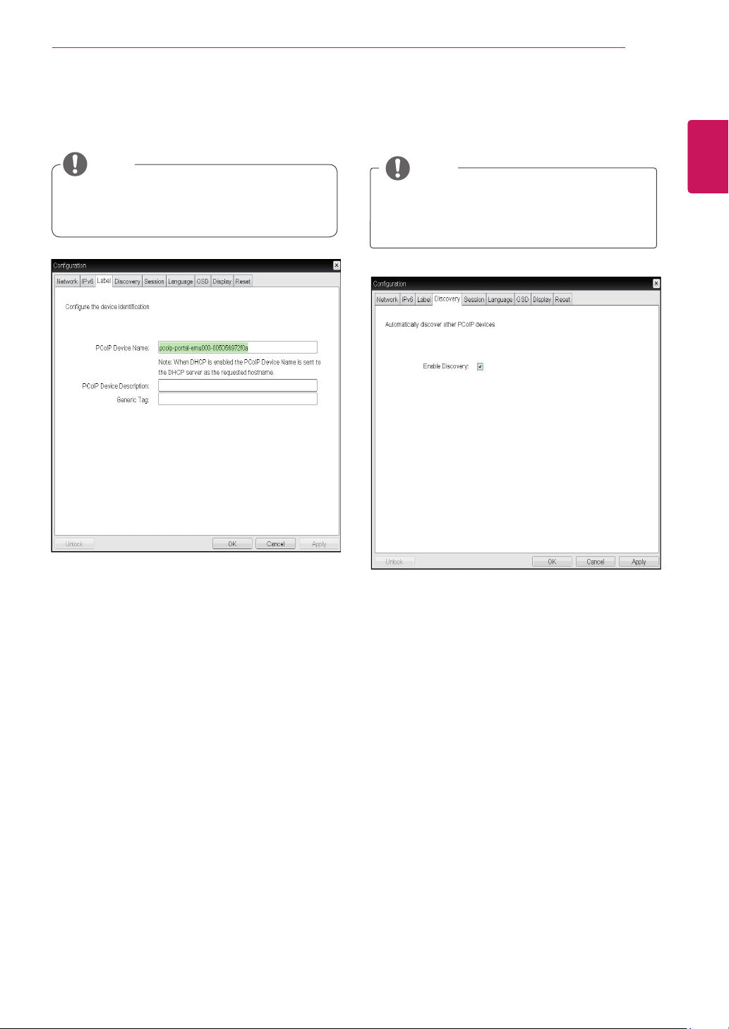
<Figure 2-9: Label Configuration>
Label Tab
The Label tab allows the administrator or host to
add customized information to the portal.
y
The portal label parameters can also be con-
figured using the Webpage Administration
Interface.
y
PCoIP Device Name
In the PCoIP Device Name field, the administrator
can specify a logical name to the host or portal.
The default value is PCoIP-host-MAC or PCoIP-
portal-MAC, where MAC is the MAC address of the
host or portal.
y
PCoIP Device Description
In the PCoIP Device Description field, the administra-
tor can add specific information, such as the endpoint
location, or add a description to the host or portal.
This field cannot be used in the PCoIP firmware and
accessibility is strictly limited to the administrator.
y
Generic Tag
In the Generic Tag field, the administrator can add a
generic tag to the host or portal.
This field cannot be used in the PCoIP firmware and
accessibility is strictly limited to the administrator.
NOTE
y
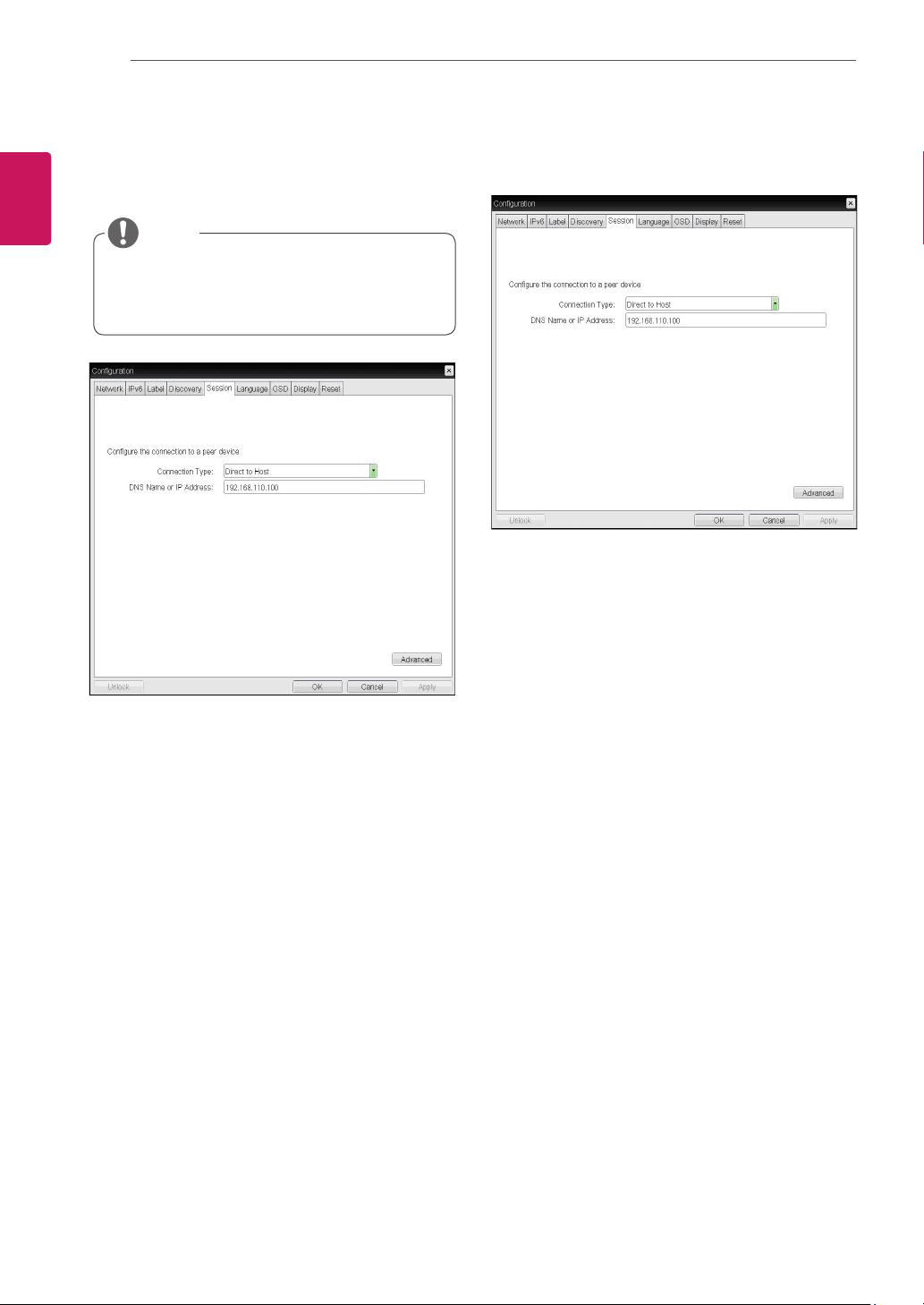
Enable Discovery
If the Enable Discovery option is selected, a device
will use SLP Discovery to dynamically locate the
peer device without requiring any information about
the location of the device in the network. This
means that the configuration and maintenance
work in a complicated system can be significantly
reduced.
As SLP Discovery requires a multicast-enabled
router, the recommended search structure is DNS-
SRV Discovery.
<Figure 2-10: Discovery Configuration>
Discovery Tab
The Discovery tab allows the administrator to eas-
ily find a portal in the PCoIP system.
y
The Discovery parameters can also be con-
figured using the Webpage Administration
Interface.
NOTE
<Figure 2-9: Label Configuration>
16
ENG
English
Using CLOUD Solution
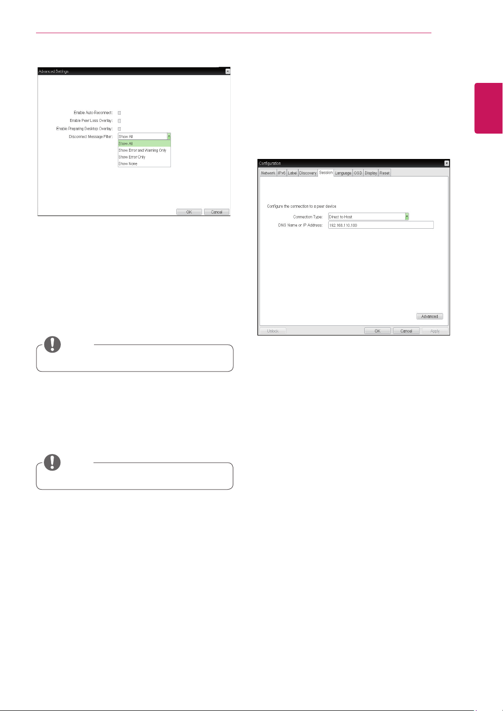
y
Direct to Host
You can view the screen of the host PC by estab-
lishing 1:1 connection between the PCI host card
connected to the host PC through the entered IP
address of the host PC and the portal.
y
DNS Name or IP Address
Enter the DNS name or IP address of the host PC.
<Figure 2-12: Direct to Host Setting>
<Figure 2-11: Session Configuration>
Session Tab
The Session tab allows the administrator to set the
method to connect the device to a peer device.
y
The Session parameters can also be con-
figured using the Webpage Administration
Interface.
NOTE
y
Connection Type
The Connection Type field allows the user to select
the device to be connected with the portal.
The Connection Type field has following options:
y
Direct to Host
y
Direct to Host + SLP Host Discovery
y
View Connection Server
y
View Connection Server + Auto-Logon
y
View Connection Server + Kiosk
y
View Connection Server + Imprivata OneSign
y
Connection Management Interface
See below for information how to set for each op-
tion.
17
ENG
English
Using CLOUD Solution
y
Enable Auto-Reconnect
If this option is selected, reconnection is attempted
automatically when a session is disconnected or
the user is logged off.
<Figure 2-13: Advanced Settings for Direct to
Host>
<Figure 2-14: Direct to Host + SLP Host Discovery Set-
tings>
y
This setting is provided only for the client.
NOTE
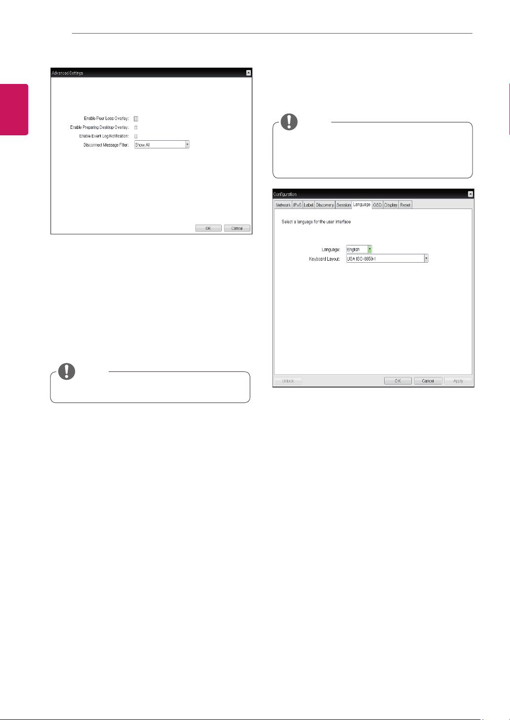
y
Enable Peer Loss Overlay
The "Connection Lost" message is displayed.The
display is the same as in the VDI environ-ment.
The default is Disable.
y
This setting is provided only for the client.
NOTE
y
Enable Preparing Desktop Overlay
If this option is selected, the "Preparing Desk-top"
message is displayed on the screen when the user
is logged in.
y
Disconnect Message Filter
This option determines the type of message to
display when a session is disconnected.
- Show All: Shows all the error messages.
- Show Error and Warning Only: Shows the
error and warning messages only.
- Show Error Only: Shows the error messages
only.
- Show None: Shows nothing.
y
Direct to Host + SLP Host Discovery
You can view the screen of the host PC by discov-
ering the host PC within the network and estab-
lishing 1:1 connection between the PCI host card
connected to the host PC and the portal.
18
ENG
English
Using CLOUD Solution
<Figure 2-15: Advanced Settings for Direct to Host
+ SLP Host Discovery>
y
Enable Auto-Reconnect
If this option is selected, reconnection is attempted
automatically when a session is disconnected or
the user is logged off.
y
This setting is provided only for the client.
NOTE
y
Enable Peer Loss Overlay
The "Connection Lost" message is displayed.The
display is the same as in the VDI environ-ment.
The default is Disable.
y
This setting is provided only for the client.
NOTE
y
Enable Preparing Desktop Overlay
If this option is selected, the "Preparing Desk-top"
message is displayed on the screen when the user
is logged in.
y
Disconnect Message Filter
This option determines the type of message to
display when a session is disconnected.
- Show All: Shows all the error messages.
- Show Error and Warning Only: Shows the
error and warning messages only.
- Show Error Only: Shows the error messages
only.
- Show None: Shows nothing.
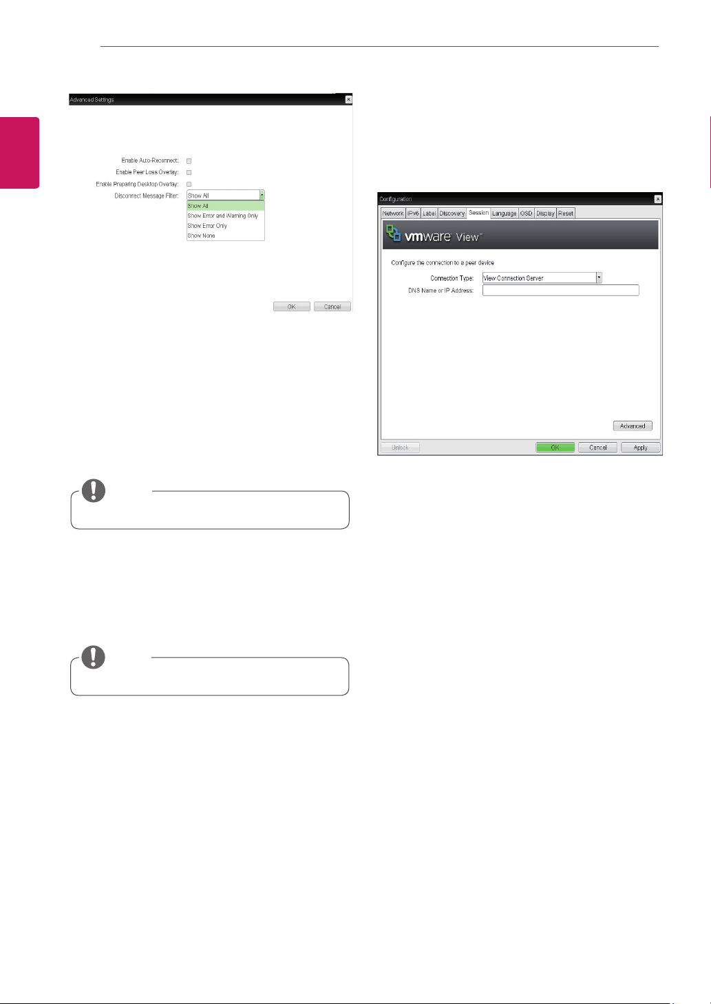
<Figure 2-16: View Connection Server Setting>
y
View Connection Server
In the Session tab, you can select to enable the
user client to access the VMware View Connec-
tionServer. To do this, select View Connection
Server for Connection Type.
y
DNS Name or IP Address
Enter the DNS name or IP address of the VM-
ware View Connection Server.
19
ENG
English
Using CLOUD Solution
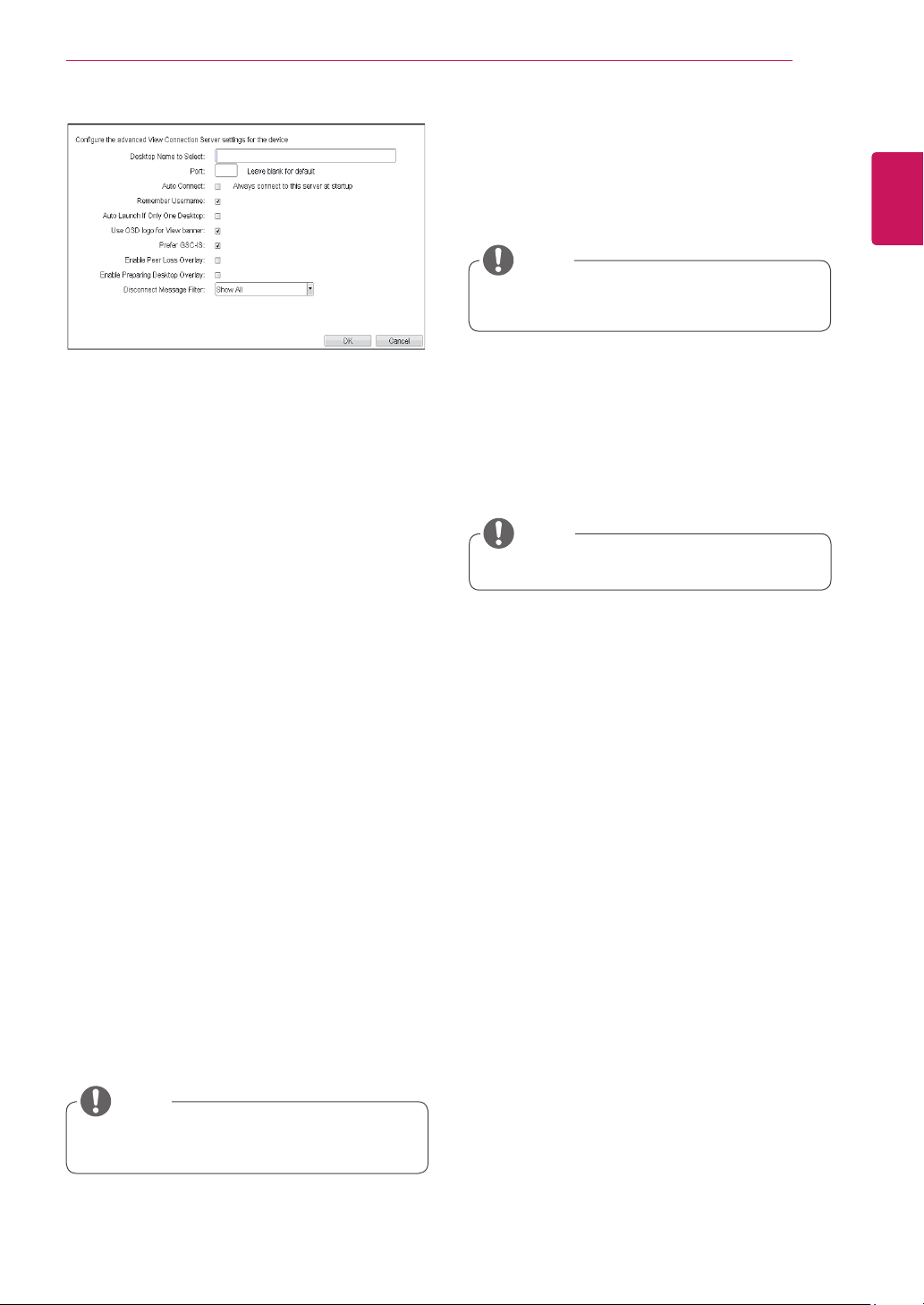
y
Desktop Name to Select
Enter the name of the pool/desktop which the
user client uses upon starting a session.
y
Port
For the default setting, leave the port field empty.
When the VMware View Connection Server uses
the SSL authentication, enter 443 in the Port field.If
the server where a user tries to access uses a port
other than a general port, enter the port.
y
Auto Connect
If this option is enabled, the selected VMware View
Connection Server is automatically connected
when the user client is powered on.
If the Auto Connect option is enabled, you should
turn the user client off and turn it on again at least
once.
y
Remember Username
If this option is selected, the username which is
previously used to access the VMware View
Connection Server is automatically entered in the
username field.
y
Auto Launch if Only One Desktop
If this option is selected, connection is established
to the desktop when there is only one virtual desk-
top that a user wants to access.
y
Use OSD logo for View banner
If this option is enabled, you can change the OSD
logo of PCoIP during the login.
<Figure 2-17: Advanced Settings for View Connec-
tion Server>
y
Prefer GSC-IS
If this option is selected, the GCS-IS interface
is used when a smart card supports more than
one interface. If the smart card supports only one
interface, it is not used.
y
The OSD logo can be uploaded using the
Webpage Administration Interface.
NOTE
y
This setting is provided only when a smart
card is used.
NOTE
y
Enable Peer Loss Overlay
If this option is selected, the "Network Connection
Lost" message is displayed on the screen when it
is confirmed that the network is disconnected.
The display is the same as in the VDI environ-
ment. The default is Disable.
y
Enable Preparing Desktop Overlay
If this option is selected, the "Preparing Desk-
top" message is displayed on the screen when the
user is logged in.
y
Disconnect Message Filter
This option determines the type of message to
display when a session is disconnected.
- Show All: Shows all the error messages.
- Show Error and Warning Only: Shows the
error and warning messages only.
- Show Error Only: Shows the error messages
only.
- Show None: Shows nothing.
y
This setting is provided only for the client.
NOTE

20
ENG
English
Using CLOUD Solution
y
Desktop Name to Select
Enter the name of the pool/desktop which the
user client uses upon starting a session.
y
Port
For the default setting, leave the port field empty.
When the VMware View Connection Server uses
the SSL authentication, enter 443 in the Port field.If
the server where a user tries to access uses a port
other than a general port, enter the port.
y
Auto Connect
If this option is enabled, the selected VMware View
Connection Server is automatically connected
when the user client is powered on.
If the Auto Connect option is enabled, you should
turn the user client off and turn it on again at least
once.
y
Remember Username
If this option is selected, the username which is
previously used to access the VMware View
Connection Server is automatically entered in the
username field.
y
Auto Launch if Only One Desktop
If this option is selected, connection is established
to the desktop when there is only one virtual desk-
top that a user wants to access.
y
Use OSD logo for View banner
If this option is enabled, you can change the OSD
logo of PCoIP during the login.
<Figure 2-19: Advanced Settings for View Connec-
tion Server with Auto-Logon>
y
View Connection Server with Auto-Logon
In the Session tab, you can select to enable the
user client to automatically access the VMware
View Connection Server.To do this, select View
Connection Server with Auto-Logon for Connection
Type.
<Figure 2-18: View Connection Server with Auto-
Logon Setting>
y
DNS Name or IP Address
Enter the DNS name or IP address of the VM-
ware View Connection Server.
y
Username
Enter the username for the user client.
y
Password
Enter the password for the user client.
y
Domain
Enter the domain name.
y
The OSD logo can be uploaded using the
Webpage Administration Interface.
NOTE
21
ENG
English
Using CLOUD Solution
y
Prefer GSC-IS
If this option is selected, the GSC-IS interface
is used when a smart card supports more than
one interface. If the smart card supports only one
interface, it is not used.
y
This setting is provided only when a smart
card is used.
NOTE
y
Enable Peer Loss Overlay
If this option is selected, the "Network Connection
Lost" message is displayed on the screen when it
is confirmed that the network is disconnected.
The display is the same as in the VDI environ-
ment. The default is Disable.
y
Enable Preparing Desktop Overlay
If this option is selected, the "Preparing Desk-
top" message is displayed on the screen when the
user is logged in.
y
Disconnect Message Filter
This option determines the type of message to
display when a session is disconnected.
- Show All: Shows all the error messages.
- Show Error and Warning Only: Shows the
error and warning messages only.
- Show Error Only: Shows the error messages
only.
- Show None: Shows nothing.
y
This setting is provided only for the client.
NOTE
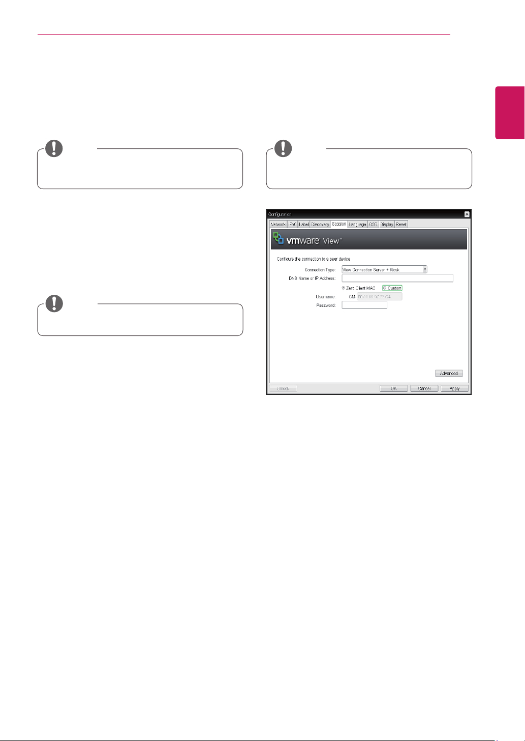
<Figure 2-20: View Connection Server + Kiosk
Setting>
y
View Connection Server + Kiosk
Select View Connection Server + Kiosk to use
the kiosk mode. You can configure the View Con-
nection Server + Kiosk mode using the Webpage
Administration Interface.
y
You cannot use the kiosk mode by connect-
ing to the host PC.
NOTE
y
DNS Name or IP Address
Enter the DNS name or IP address of the VM-
ware View Connection Server.
y
Username
Select the type of username that matches the de-
vice name used in the VMware View Con-
nection Server.
y
Password
Enter the password for the user client.
22
ENG
English
Using CLOUD Solution
<Figure 2-21: Advanced Setting for View Connec-
tion Server + Kiosk>
<Figure 2-22: View Connection Server + Imprivata One-
Sign Connection Setting>
y
Port
For the default setting, leave the port field empty.
When the VMware View Connection Server uses
the SSL authentication, enter 443 in the Port field.
If the server where a user tries to access uses a
port other than a general port, enter the port.
y
Use OSD logo for View banner
If this option is enabled, you can change the OSD
logo of PCoIP during the login.
y
The OSD logo can be uploaded using the
Webpage Administration Interface.
NOTE
y
Enable Peer Loss Overlay
If this option is selected, the "Network Connection
Lost" message is displayed on the screen when it
is confirmed that the network is disconnected.
The display is the same as in the VDI environ-
ment. The default is Disable.
y
This setting is provided only for the client.
NOTE
y
Enable Preparing Desktop Overlay
If this option is selected, the "Preparing Desk-
top" message is displayed on the screen when the
user is logged in.
y
Disconnect Message Filter
This option determines the type of message to
display when a session is disconnected.
- Show All: Shows all the error messages.
- Show Error and Warning Only: Shows the
error and warning messages only.
- Show Error Only: Shows the error messages
only.
- Show None: Shows nothing.
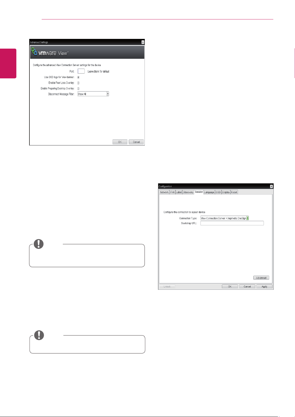
y
View Connection Server + Imprivata OneSign
Connection
Select View Connection Server + Imprivata One-
sign Connection to use the Imprivata One-
sign Connection for the client authentication.
y
Bootstrap URL
Enter the IP address or FQDN information of the
server which performs the OneSign au-
thentication.
23
ENG
English
Using CLOUD Solution
<Figure 2-23: Advanced Settings for View Connec-
tion Server + Imprivata OneSign Connection>
y
Remember Username
If this option is selected, the username which is
previously used to access the VMware View
Connection Server is automatically entered in the
username field.
y
Use OSD logo for View banner
If this option is enabled, you can change the OSD
logo of PCoIP during the login.
y
The OSD logo can be uploaded using the
Webpage Administration Interface.
NOTE
y
Prefer GSC-IS
If this option is selected, the GCS-IS interface
is used when a smart card supports more than
one interface. If the smart card supports only one
interface, it is not used.
y
This setting is provided only when a smart
card is used.
NOTE
y
Enable Peer Loss Overlay
If this option is selected, the "Network Connection
Lost" message is displayed on the screen when it
is confirmed that the network is disconnected.
The display is the same as in the VDI environ-
ment. The default is Disable.
y
This setting is provided only for the client.
NOTE
y
Enable Preparing Desktop Overlay
If this option is selected, the "Preparing Desk-
top" message is displayed on the screen when the
user is logged in.
y
Disconnect Message Filter
This option determines the type of message to
display when a session is disconnected.
- Show All: Shows all the error messages.
- Show Error and Warning Only: Shows the
error and warning messages only.
- Show Error Only: Shows the error messages
only.
- Show None: Shows nothing.
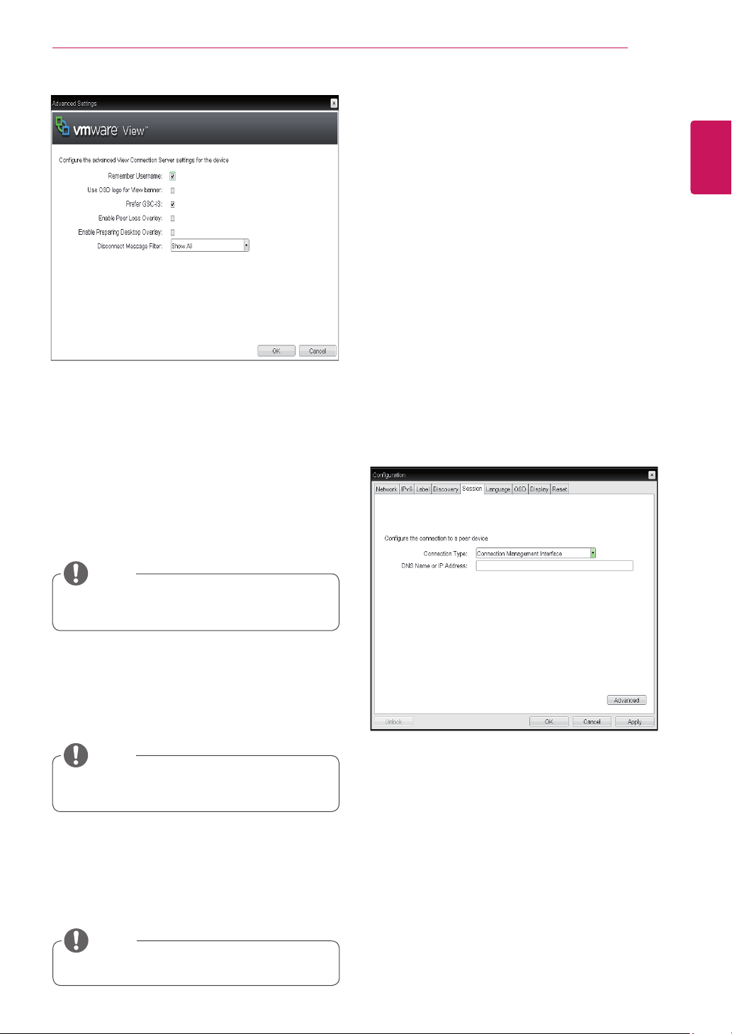
y
Connection Management Interface
In the Connection Management Interface setting,
you can manage the connection by entering the IP
address for connection management instead of us-
ing the IP address of the VMware View Connection
Server and can select to enable or disabled the
management interface.
<Figure 2-24: Connection Management Interface
Setting>
y
DNS Name or IP Address
Enter the DNS name or IP address of the VMware
View Connection Server.
24
ENG
English
Using CLOUD Solution
y
Language
The Language field is used to set the display
language of the OSD and the user level event log
messages.
y
Keyboard Layout
The Keyboard Layout field allows the administrator
to modify the keyboard layout.
<Figure 2-26: Language Configuration>
Language Tab
The Language tab allows the administrator to set
the OSD language.
y
The Language parameters can also be con-
figured using the Webpage Administration
Interface.
NOTE
<Figure 2-25: Advanced Settings for Connection
Management Interface>
y
Enable Peer Loss Overlay
If this option is selected, the "Network Connection
Lost" message is displayed on the screen when it
is confirmed that the network is disconnected.
The display is the same as in the VDI environ-
ment. The default is Disable.
y
This setting is provided only for the client.
NOTE
y
Enable Preparing Desktop Overlay
If this option is selected, the "Preparing Desk-
top" message is displayed on the screen when the
user is logged in.
y
Enable Event Log Notification
With this option, you can select whether to allow
the host and client device to send their event log
information to the Connection Management Server.
y
Disconnect Message Filter
This option determines the type of message to
display when a session is disconnected.
- Show All: Shows all the error messages.
- Show Error and Warning Only: Shows the
error and warning messages only.
- Show Error Only: Shows the error messages
only.
- Show None: Shows nothing.
25
ENG
English
Using CLOUD Solution
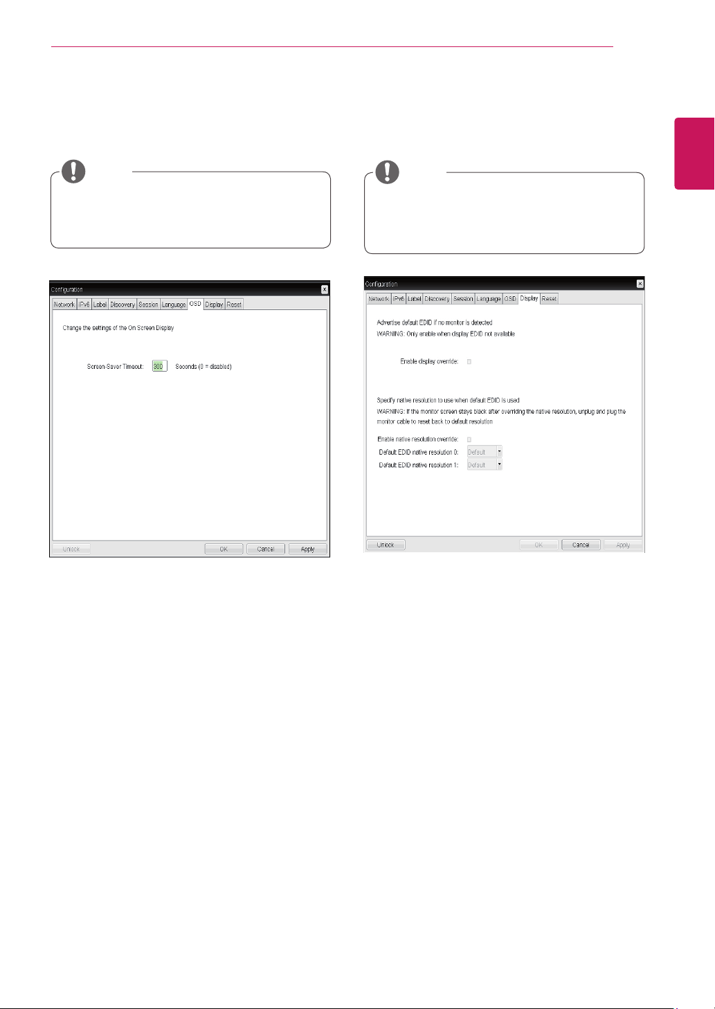
y
Screen-Saver Timeout
The Screen-Saver Timeout field allows the ad-
ministrator to set a time limit for the screen saver.
The time limit is defined in seconds. The maximum
time is 9999 seconds. If it is set to 0 seconds, the
screen saver will be turned off.
<Figure 2-27: OSD Configuration>
OSD Tab
The OSD tab allows the administrator to modify the
On Screen Display (OSD) parameters.
y
The OSD parameters can also be configured
using the Webpage Administration Interface.
NOTE
<Figure 2-28: Display Configuration>
Display Tab
The Display tab allows the user to configure the
EDID function of the monitor.
y
The Enable display override function can be
used when the EDID function of the monitor
is not running.
NOTE
26
ENG
English
Using CLOUD Solution
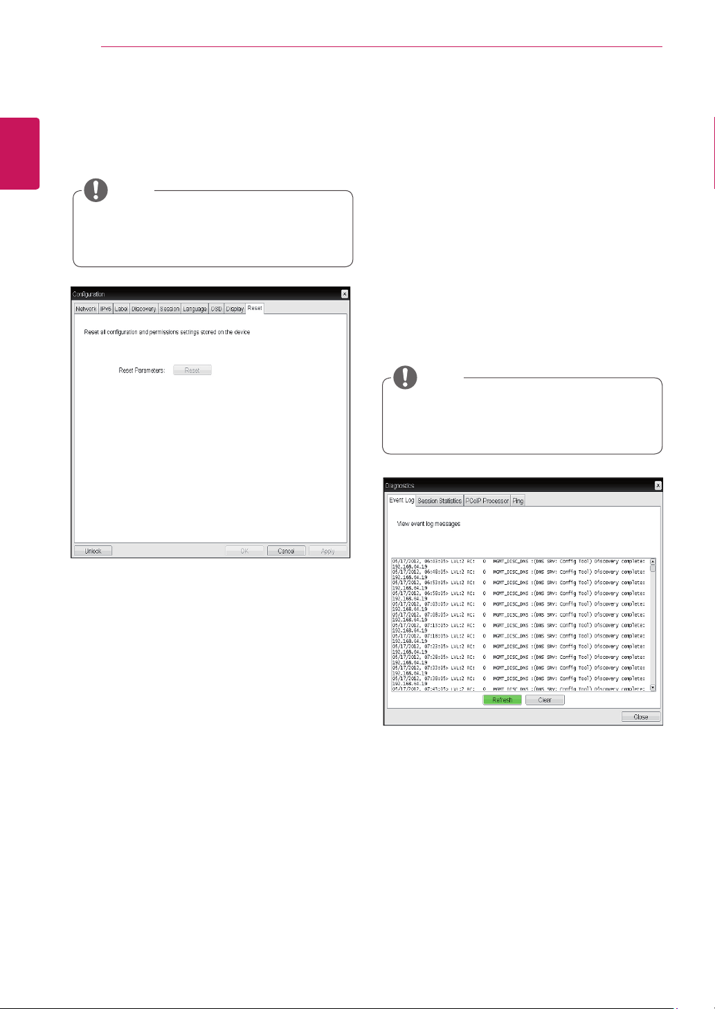
y
Reset Parameters
Pressing the Reset Parameters button will reset all
settings and options to the factory default settings.
When this button is pressed, an OSD message is
displayed. This is to prompt the administrator and
prevent accidental reset.
<Figure 2-29: Reset>
Reset Tab
The Reset tab allows the administrator to reset all
configurable parameters stored in Flash.
y
The Reset function can also be accessed
through the Webpage Administration Inter-
face.
NOTE
y
Event Log
y
Session Statistics
y
PCoIP Processor
y
Ping
Each tab has the Close button to close the window.
Diagnostics Window
In the Diagnostics window, the administrator can
access the window tab to diagnose the portal. The
Diagnostics window has the following tabs:
y
View Event Log Message
The View Event Log Message field displays the log
messages accompanied by the timestamp informa-
tion. The following two buttons are available:
y
Refresh
The Refresh button refreshes the displayed event
log messages.
y
Clear
The Clear button clears all event log messages.
<Figure 2-30: Event Log>
Event Log Tab
The Event Log tab allows the administrator to view
and delete the event log messages from the portal.
y
The event log (regardless of the quantity)
can also be reset using the Webpage Admin-
istration Interface.
NOTE
27
ENG
English
Using CLOUD Solution
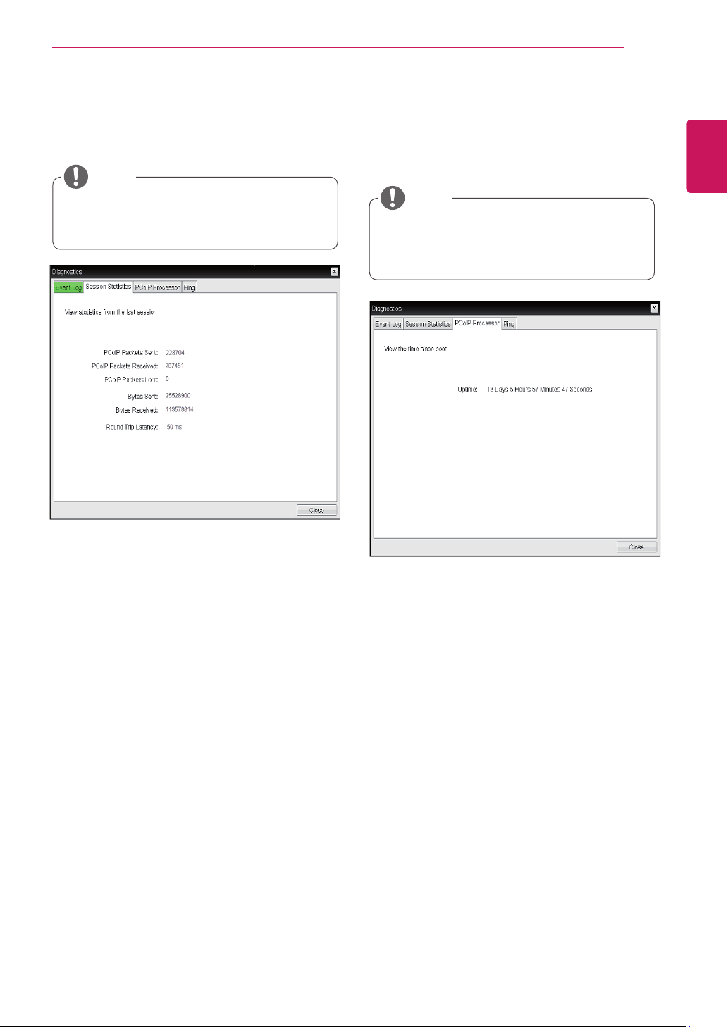
y
PCoIP Packets Statistics
y
PCoIP Packets Sent
The PCoIP Packets Sent field shows the total
number of PCoIP packets sent from the portal
to the host in the last active session.
y
PCoIP Packets Received
The PCoIP Packets Received field shows the
total number of PCoIP packets received from
the host to the portal in the last active session.
y
PCoIP Packets Lost
The PCoIP Packets Lost field shows the total
number of PCoIP packets lost in the last ac-
tive session.
<Figure 2-31: Session Statistics>
Session Statistics Tab
The Session Statistics tab allows the administrator
to view the PCoIP specific statistics of the last ac-
tive PCoIP session from the portal.
y
Bytes Statistics
y
Bytes Sent
The Bytes Sent field shows the total number
of bytes sent in the last active session.
y
Bytes Received
The Bytes Received field shows the total
number of bytes received in the last active
session.
y
Round Trip Latency
The Round Trip Latency field shows the total
round-trip PCoIP system (e.g. from the portal to
the host, then back to the portal) and the network
latency in milliseconds (+/- 1 ms).
y
The session statistics (regardless of the
quantity) can also be viewed using the Web-
page Administration Interface.
NOTE
<Figure 2-32: PCoIP Processor>
PCoIP Processor Tab
The PCoIP Processor tab allows the administrator
to view the portal PCoIP processor's uptime since
its last booting.
y
The PCoIP Processor Uptime can also be
viewed using the Webpage Administration
Interface.
NOTE
28
ENG
English
Using CLOUD Solution
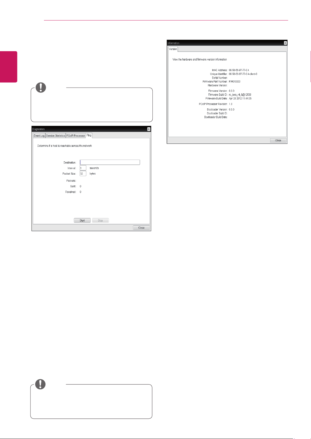
y
Ping Settings
y
Destination
The IP address or FQDN to perform the ping
test.
y
Interval
The interval between the ping packets.
y
Packet Size
The size of the ping packet.
y
Packets
y
Sent
The number of ping packets sent.
y
Received
The number of ping packets received.
<Figure 2-33: Ping>
Ping Tab
The Ping tab allows the administrator to perform a
ping test to the device and check if it can reach the
overall IP network. This is useful to check whether
the device can reach the host.
y
The Ping tab has no corresponding menu in
to the Webpage Administration Interface of
Section 1.
NOTE
y
VPD Information
The Vital Product Data (VPD) is information that
uniquely identifies each portal or host.
y
MAC Address
The portal MAC address
y
Unique Identifier
The portal ID
y
Serial Number
The portal serial number
y
Firmware Part Number
The part number of the PCoIP firmware
y
Hardware Version
The portal hardware version
y
Firmware Information
The Firmware Information shows the details of the
current PCoIP firmware.
y
Firmware Version
The current PCoIP firmware version
y
Firmware Build ID
The current PCoIP firmware revision code
y
Firmware Build Date
The current PCoIP firmware build date
<Figure 2-34: Version>
Information Window
In the Information window, the administrator can
access the Version tab that contains the device
related information.
y
The version information can also be viewed
using the Webpage Administration Interface.
NOTE
y
Boot Loader Information
The Boot Loader Information shows the details of
the current PCoIP boot loader.
y
Boot Loader Version
The current PCoIP boot loader version
y
Boot Loader Build ID
The current PCoIP boot loader revision code
y
Boot Loader Build Date
The current PCoIP boot loader build date
PCoIP Processor Revision
This shows the PCoIP processor's revision code.
TERA1x00 Revision A silicone is denoted by 0.0
and TERA1x00 Revision B silicone is denoted by
1.0.
29
ENG
English
Using CLOUD Solution
User Settings Window
In the User Settings window, the administrator can
access the tab to select the mouse and keyboard
and define the PCoIP image quality.
The User Settings window has the following tabs:
y
VMware View
y
Mouse
y
Keyboard
y
Image
y
Display Topology
y
Touch Screen
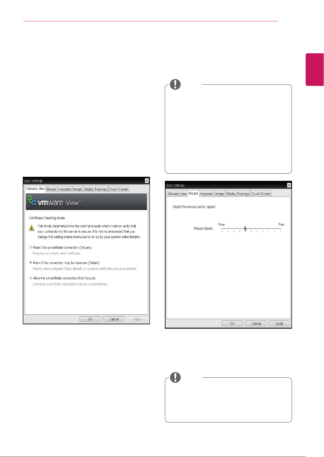
y
Mouse Speed
The Mouse Speed field allows the user to set the
portal's mouse cursor speed.
<Figure 2-36: Mouse>
Mouse Tab
The Mouse tab allows the user to modify the OSD
and RDP session's mouse cursor speed setting.
y
The OSD mouse cursor speed setting does
not affect the mouse cursor settings when
a PColP session is active unless the Local
Keyboard Host Driver function is being used
(see PColP Host Software User Guide for
more information).
y
The Mouse tab has no corresponding menu
in the Webpage Administration Interface of
Section 1.
y
The Mouse Speed can also be configured via
the PCoIP Host Software. For more informa-
tion on using the PCoIP Host Software, refer
to the PCoIP Host Software User Guide.
NOTE
NOTE
<Figure 2-35: VMware View>
y
VMware View Tab
The VMware View tab allows user to specify the
client behavior for when a user cannot check the
secure connection to a server.
y
Reject the unverifiable connection (Secure)
Connection can be established only when the cer-
tificate is verified and otherwise it cannot.
y
Warn if the connection may be insecure (De-
fault)
The authentication status is checked and a warn-
ing message is displayed, if required. However,
there is no connection limit.
y
Allow the unverifiable connection (Not Se-
cure)
No authentication is required and no connec-tion
limit exists.
30
ENG
English
Using CLOUD Solution
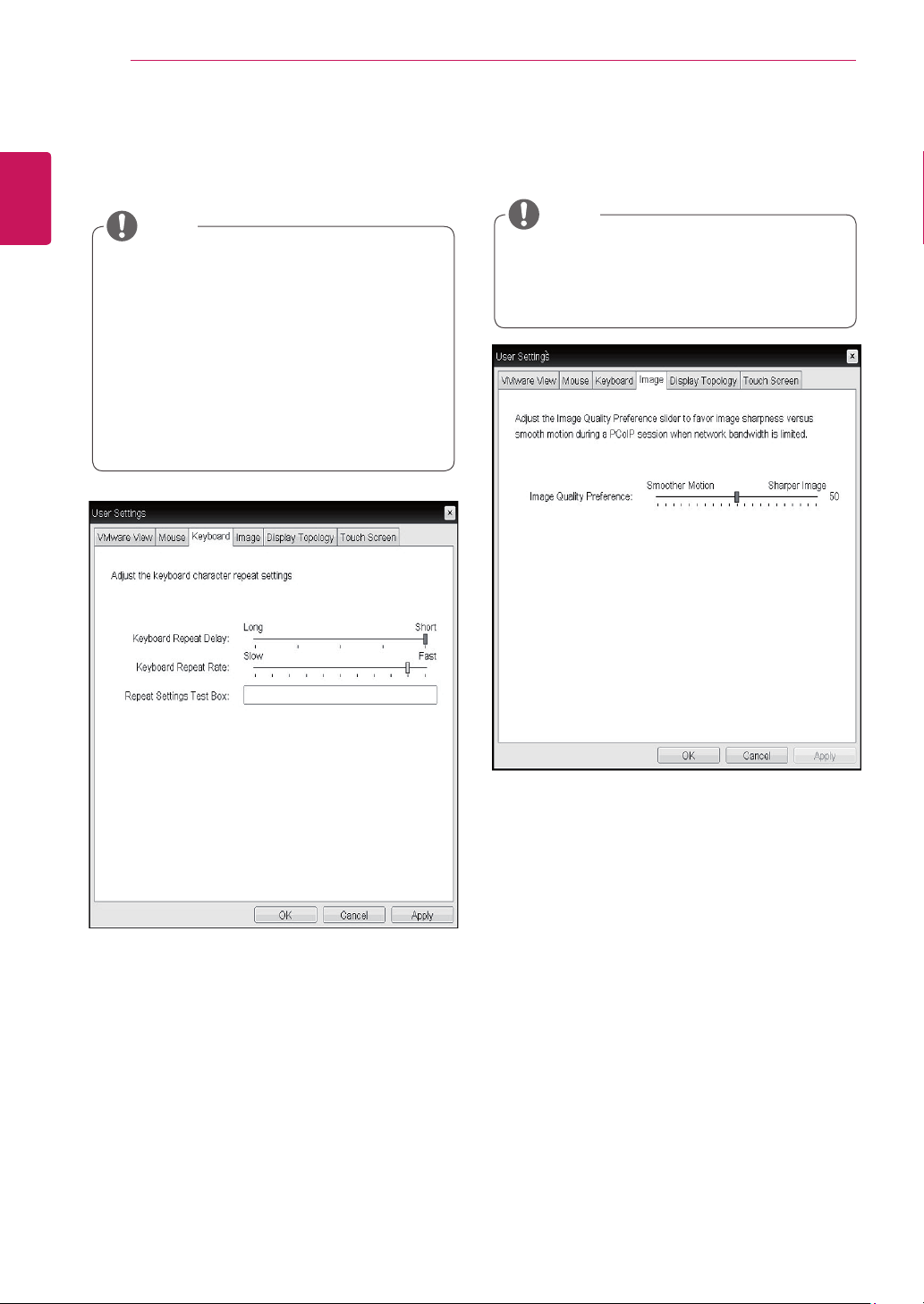
y
Keyboard Repeat Delay
The Keyboard Repeat Delay field allows the user
to set the portal's keyboard repeat delay.
y
Keyboard Repeat Rate
The Keyboard Repeat Rate field allows the user to
set the portal's keyboard repeat rate.
y
Repeat Settings Test Box
The Repeat Settings Test Box allows the user to
test the selected keyboard settings.
<Figure 2-37: Keyboard>
Keyboard Tab
The Keyboard tab allows the user to modify the
OSD and RDP session's keyboard repeat setting.
y
The OSD keyboard setting does not affect
the keyboard settings when a PColP session
is active unless the Local Keyboard Host
Driver function is being used (see PColP
Host Software User Guide for more informa-
tion).
y
The Keyboard tab has no corresponding
menu in the Webpage Administration Inter-
face of Section 1.
NOTE
y
Minimum Image Quality
The Minimum Image Quality slider allows the ad-
ministrator to make compromises between image
quality and frame rate when network bandwidth
is limited. Sometimes, lower-quality images at a
higher frame rate may be required, while at other
times, higher-quality images at a lower frame rate
may be preferred.
In environments where the network bandwidth is
limited, moving the slider towards Reduced en-
sures higher frame rates;
moving the slider towards Perception-Free ensures
higher image quality. When network bandwidth is
not limited, the PCoIP system will maintain percep-
tion-free quality regardless of the Minimum Image
Quality setting.
<Figure 2-38: Image>
Image
The Image tab allows a user to change the image
settings on the PCoIP system.
y
The Image parameters can also be con-
figured using the Webpage Administration
Interface.
NOTE
31
ENG
English
Using CLOUD Solution
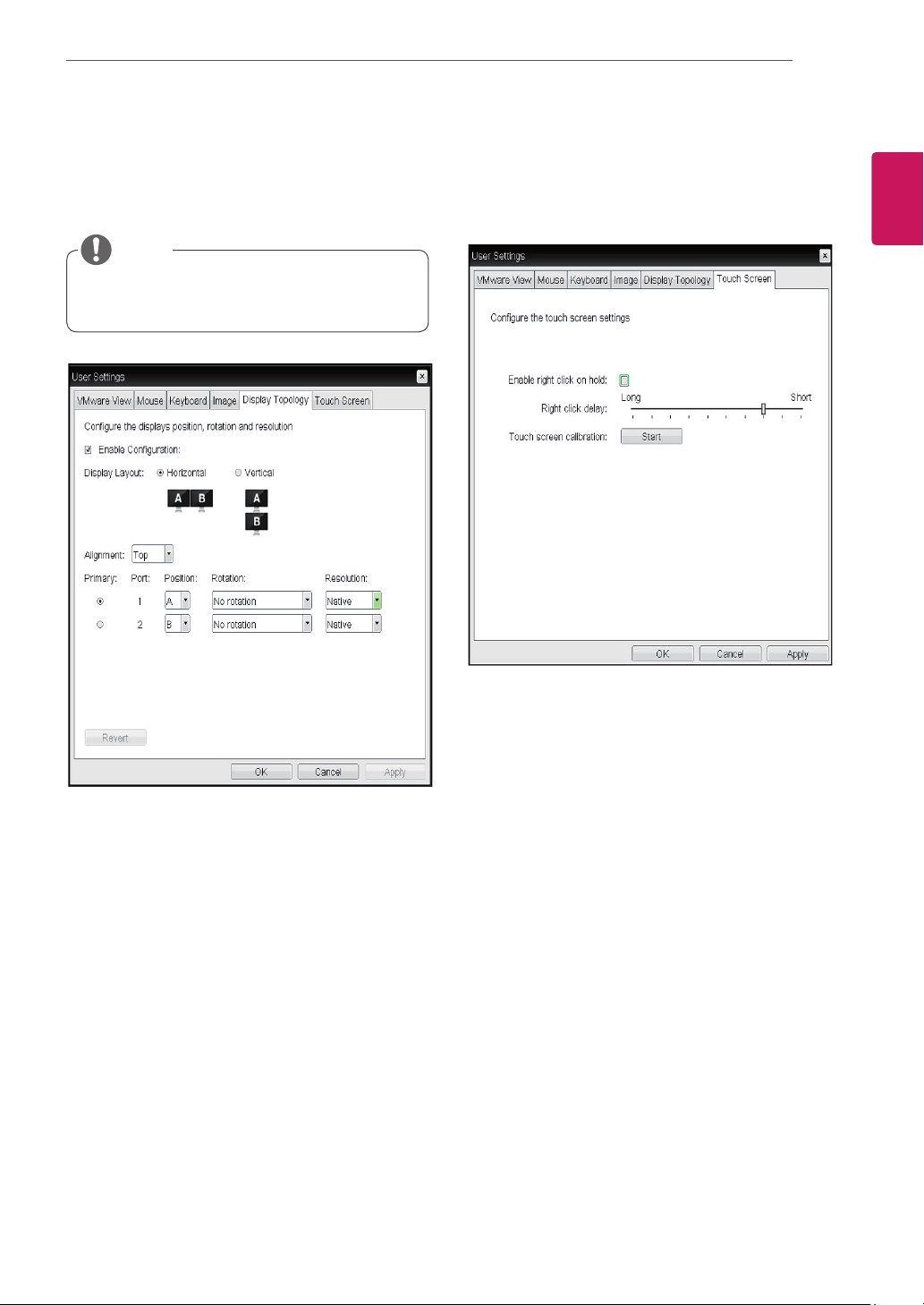
y
Display Topology Tab
The Display Topology tab allows the user to specify
the position and alignment of a connected second-
ary monitor.
y
It is applicable when the VMware View Con-
nection Server version is 4.5 or later.
NOTE
<Figure 2-39: Display Topology>
y
Enable Configuration
When this option is selected, you can set the
display position and alignment. You can save the
settings by clicking the Apply or OK button, and
the settings will be reset if you initialize the monitor
set.
y
Display Layout
This option allows the user to specify the direction
of monitor connection: vertical or horizontal.
y
Alignment
This option allows the user to specify the align-
ment position of the monitor to be connected when
there is a resolution difference between the two
monitors.
y
Primary
This option allows the user to change the primary/
secondary settings of the connected monitor.
y
Touch Screen Tab
The Touch Screen tab allows the user to specify
the touch sensitivity and alignment when the moni-
tor supports the touch screen function.
<Figure 2-40: Touch Screen>
y
Enable right click on hold
If this option is selected, clicking and holding the
touch screen for several seconds works the same
as the mouse right click.
y
Right Click Delay
This option allows the user to make moving the
pointer position work the same as the mouse right
click. You can also specify the distance to move
(from Long to Short).
y
Touch screen calibration
The alignment of a touch screen is started when
clicking the Start button.

The product label contains necessary
information for after-service.
Model
Serial No.
To obtain the source code under GPL, LGPL,
MPL and other open source licenses, that is
contained in this product, please visit http://
opensource.lge.com .
In addition to the source code, all referred
license terms, warranty disclaimers and
copyright notices are available for download.
LG Electronics will also provide open source
code to you on CD-ROM for a charge covering
the cost of performing such distribution (such
as the cost of media, shipping and handling)
upon email request to opensource@lge.com.
This offer is valid for three (3) years from the
date on which you purchased the product.


