Loading ...
Loading ...
Loading ...
40
Regulating the minimum flame
After lighting the burners, turn the control knob to the minimum setting and then remo-
ve the knob (this can easily be removed by apply a gentle pressure).
Using a small «Terminal» type screwdriver the regulating screw can be adjusted as in
Fig. 8. Turning the screw clockwise reduces the gas flow, whilst turning it anticlockwise
increases the flow – Use this adjustment to obtain a flame of approximately 3 to 4 mm
in length and then replace the control knob.
If GPL (cylinder) gas is being used, turn the screw clockwise right to the end of the
travel of the by-pass.
Screws regulating
(for differend models)
ATTENTION: When cleaning the hob, take care to replace the burners correctly,
this will ensure that the ignition point is not blocked.
GENERAL ADVICE
For the best results, the flat-bottomed pans size should match the gas burner size as
follows:
— Front right burner from 6 to 12 cm.
— Front left burner from 24 to 26 cm.
— Back left burner from 12 to 18 cm.
— Back right burner from 18 to 24 cm.
See fig. 1b pag. 34.
For smaller containers the gas burner should be regulated so that the flame does not
overlap the base of the pan. Vessels with concave or convex base should not be used.
WARNING: If a burner is accidentally extinguehed, turn the knob to the off posi-
tion and do not attempt to re-ignite if for at least 1 minute.
To protect the glass lid from damage and in the interests of safety, the burners/plates
must be turned off and the burner/pan support/plate area must be cool before closing
the lid down.
Use of electric hotplates (electric hotplates)
For the best use of the electric hotplates and to minimise energy consumption, the fol-
lowing recommendations should be noted.
USE OF HOB
User instructions
This appliance must only be used for the purpose for which it is intended, domestic
cooking, and any other use will be considered improper and could therefore be danger-
ous. The Manufacturer will not be responisble for any damage or loss resulting from
improper use.
Using the gas Burner
To ignite the burners, place a lighted taper close to the burner, press in and turn the
control knob anti-clockwise.
If the burners have not been used for a couple of days, wait for a few seconds before
lighting the burner, this will allow any air present in the pipes to escape.
For appliances fitted with electronic ignition carry out the following:
• push in and turn the knob anticlockwise to the symbol.
• ignite the burner by pressing the sparker button.
For hobs fitted with automatic ignition simply push in and turn the knob to the sym-
bol.
The ignition generator is a repetitive discharge type.
If the burner is not ignited within 5 seconds, turn the knob to the 0 position and repeat
the operation.
For models fitted with a safety tap (which cuts-off the flow of gas if the flame is acci-
dentally extinguished) the burners are ignited ad described above, but care must be
taken to keep the knob pressed in for 5 or 6 seconds after the flame is ignited.
39
Fig. 6 Fig. 7
BURNER CAP
BURNER
AIR REGULATION
SCREW
FIXING
SCREW
SMALL
MEDIUM
LARGE
DOUBLE RING
MAXI
For dimensions «X» see table of gas consumption
When you have carried out the new gas regulation, replace the old gas rating pla-
te on your appliance with one (supplied with hob) suitable for the type of gas for
which it has been regulated.
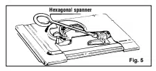
Lubricating the gas taps
If a gas tap becomes stiff, it should be dismantled, cleaned carefully with petrol and
smeared with a drop of special heat resistant grease.
The following operations should be carried but:
— disconnect the electrical power supply, close the gas supply tap from the mains or
cylinder.
— Remove the knobs and the plate by removing the screws located at the rear of the
plate itself and beneath the individual burners.
— Remove the two screws holding down the head flange.
— Remove the head flange and the retaining spring on the knob shaft.
— Remove the gas regulation cone, clean it with petrol and smear it with some heat
resistant grease, taking care not to obstruct any holes through which gas must pass.
— Re-assemble all the parts, making sure that the spring and the rotating axis of the
cone fitted to the knob shaft are correctly seated.
Fig. 8
Loading ...
Loading ...
Loading ...