Loading ...
Loading ...
INFORMATION CONCERNING INSTALLATION
1) Use only DC power Supply (kindly check the technical data sheet).
2) When selecting appropriate power supply, please take into account, the electric power
consumed by LED Neon Flex (kindly check the technical data sheet).
3) In case when section is longer than 5M/10M, we recommend to power strips from the
ends
11. Once the LED Neon flex is cut it loses its IP X5. To ensure and regain its IP use
Silicone and ensure the IP is secured. Place End Cap at the end of LED Neon Flex
REMARKS CONCERNING MAINTENANCE
1) Use dry delicate cloth for cleaning.
2) Switch off the LED Neon Flex, prior to cleaning and make sure that the plug is pulled
out of the outlet.
3) Please wait until the lamp cools down in case it is heated.
4) During cleaning, follow the general safety rules and always be careful.
REMARKS CONCERNING SAFETY
1) The product should be safeguarded from children and in any case, should not be the
subject of play.
2) If the product is damaged, it should not be used (Advisably for recycling).
3) To be used for indirect lighting/architectural purpose only.
4) The manufacturer is not responsible for any damage arisen from not following safety
instruction or misuse of product.
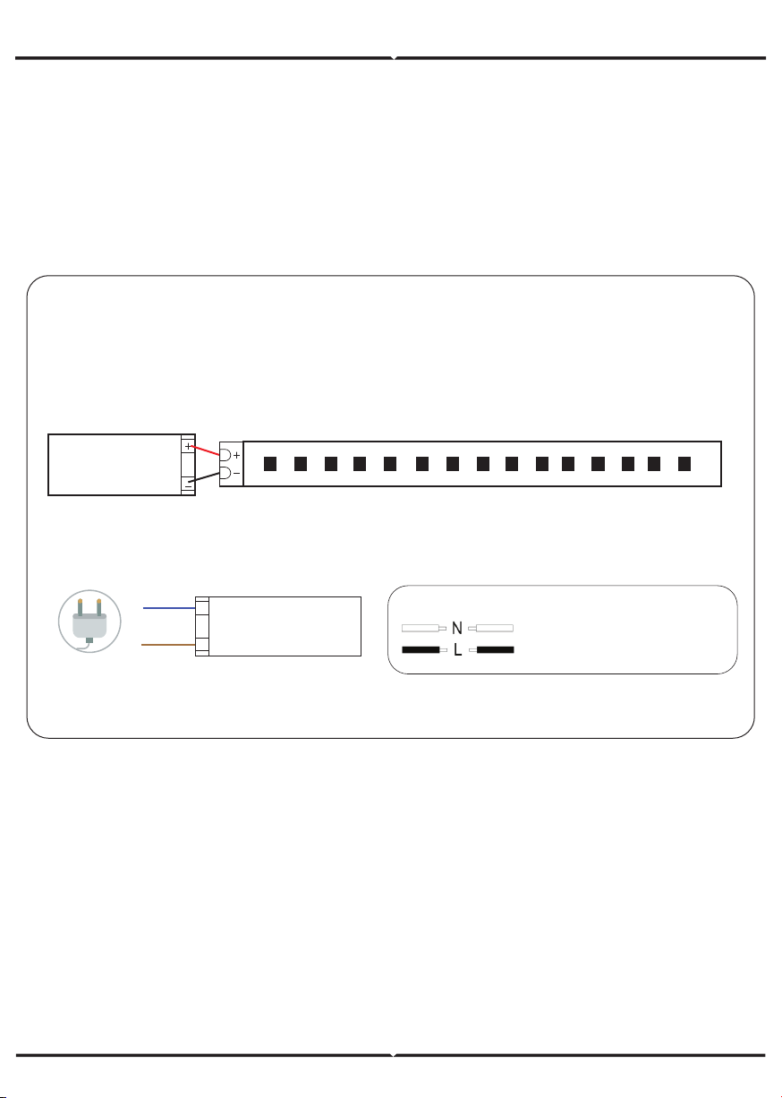
INSTALLATION INSTRUCTIONS
Step 1: Switch Off the power before starting the installation.
Step 2: Connect the LED Neon Flex polarity “+” and “-” to the driver’s polarity “+”
and “-”. Follow the wiring diagram to ensure the wiring is done correctly [Refer to
Figure 1].
DC24V Power
Red wire should be connected to positive (+) side of the power supply.
Black wire should be connected to negative (-) side of the power supply.
Figure 1
Step 3: Wire the AC input source to the power supply and the AC plug. Additional
waterproof measure needed when used outdoors.
Step 4: Switch on the power to test the light.
AC IN
DC OUT
N
L
Power Supply
AC Power
WIRING DIAGRAM
Live Supply Can be Red or Brown
Neutral Supply can be Blue or Black
Loading ...
Loading ...
Loading ...