Owner 's Manual for Downdraft
USING THE VENT SYSTEM
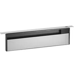
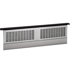
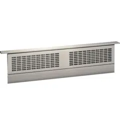
Downdraft Vent System
To Use The Downdraft System
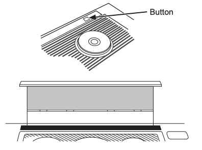
To raise the downdraft vent, press the button on the top cover. The vent will rise.
The blower can be turned ON or OFF and the speed can be adjusted with the recessed knob on the right side of the air vent. The blower, if left on, will automatically turn off when the vent is lowered.
NOTE: For most convenient operation, set the blower to the speed you use most often. The blower will come on to this speed whenever the unit is raised.
Lower the downdraft vent by pressing the button on the top cover. The vent will go down an the blower will shut off.
When Using The Vent System
CAUTION Be careful when raising or lowering the vent. Be sure pots, pot handles and other objects are clear of the vent and cannot be struck or tipped by the vent being raised.
NOTE: There is a slight trim overhang on each side of the vent.
- To avoid injury. be sure fingers are clear of the vent cover when it is being lowered.
- Keep hands and fingers away from all vent parts.
IMPORTANT: If the vent is obstructed by an object while it is being raised or lowered, it will stop. Carefully remove the obstruction and the vent will drop to the lowered position. Press the button again to return to normal functons.
Cooking Tips
The high air movement of this vent system can increase the cooking times for some foods. It may take longer to reach high cooking temperatures if the vent system is turned to high right away. Adjust the fan speed for best cooking results.
For best results when heating oil for deep frying or when boiling water, use the front surface units or wait until the water is boiling or the oil is at frying temperatures before turning on the vent system.
The vent system may not completely capture all the steam from pans on the front burners.
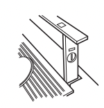
Grease Filters
The efficiency of your vent system depends on a clean filter. Frequency of cleaning depends on the type of cooking you do. Grease filters should be cleaned at least once a month. Never operate the vent system without the filters in place.
To remove: Remove filters from the air vent by reaching the filters through the vent openings, pushing down then pulling out. NOTE: The filters are different sizes. Be sure to replace them as removed, wider one on the left
To clean: Soak and then agitate in a hot detergent solution. Light brushing may be used to remove embedded soil. Rinse, shake and remove moisture before replacing. Do not clean the filters in the dishwasher.
With careful handling, the filter will last for years. If replacement becomes necessary, order the part from your dealer.

Painted Or Stainless Steel Surfaces
Do not use a steel wool pad; it will scratch the surface. To clean the stainless steel surface, use warm, sudsy water or a stainless steel cleaner or polish. Always wipe the surface in the direction of the grain. Follow the cleaner instructions for cleaning the stainless steel surface.
For difficult stains on stainless steel, use a cleaner that contains lactic acid or citric acid.
To inquire about purchasing cleaning products including stainless steel appliance cleaner or polish read the Assistance and Accessories sections at the beginning of this manual.
INSTALLATION INSTRUCTIONS
Installation Preparation
POWER SUPPLY
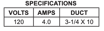
This downdraft vent must be supplied with 120V, 60 Hz. and connected to an individual, properly grounded branch circuit, protected by a 15- or 20-ampere circuit breaker or time-delay fuse.
A properly grounded 3-prong receptacle should be located within reach of the vent’s two-foot power cord.
If this vent is installed in combination with a GE or Monogram gas cooktop, it may operate from the same duplex outlet.
If this vent is installed in combination with a GE or Monogram electric cooktop, the vent must operate from a separate 120V outlet.
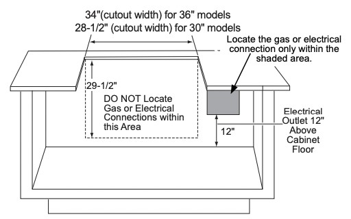
Locate the receptacle inside the cabinet on the right side wall (see illustration). The receptacle cannot be placed on the back of the cabinet wall where it may interfere with the downdraft plenum.
The downdraft vent power cord is to be routed beneath the cooktop and routed away from heat generated by the cooktop.
Ensure that the cooktop is installed per manufacturer’s installation instructions.
IMPORTANT (Please read carefully)
The power cord of this appliance is equipped with a three-prong (grounding) plug which mates with a standard three-prong grounding wall receptacle to minimize the possibility of electric shock. The customer should have the wall receptacle and circuit checked by a qualified electrician to make sure the receptacle is properly grounded and has correct polarity.
- Where a standard two-prong wall receptacle is encountered, it is the personal responsibility and obligation of the customer to have it replaced with a properly grounded three-prong wall receptacle.
Do not, under any circumstances, cut or remove the third (ground) prong from the power cord.
Do not use an extension cord or adapter plug with this appliance. Follow National Electrical Code or prevailing local codes and ordinances.
Location of Rating Label: on front of chassis of vent system.
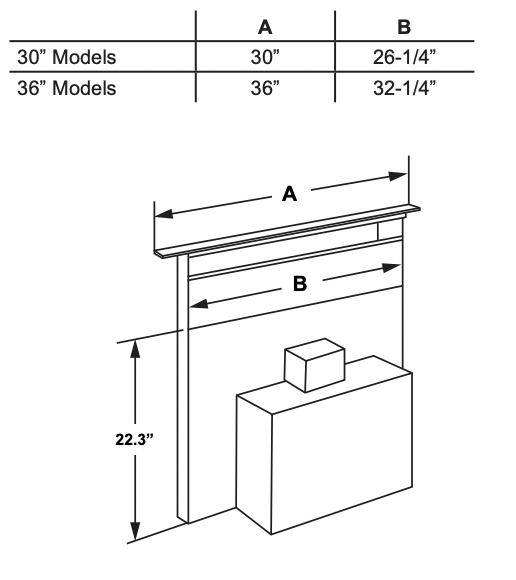
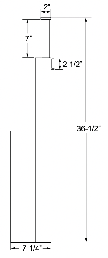
PRODUCT DIMENSIONS
PREPARING FOR INSTALLATION
- Unpack the cooktop and read the Installation Instructions to understand the required countertop cutout dimensions and location in the countertop, the cooktop spacing to the front edge of the countertop, and the required clearances to the cabinets and walls. The vent system required cutout width is shown on page 9. Confirm there is enough side to side counter space to meet the required spacing and clearances for the cooktop.
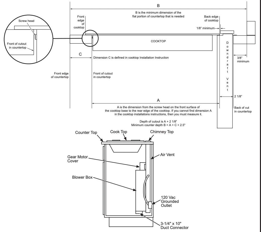
- Using the illustrations below and taking measurements of the cooktop to establish dimension A, confirm there is enough front to back counter space (dimension B) to fit both the cooktop and the vent system. Note the cooktop rear edge will overlap the vent system front surface (refer to Page 10).
- Refer to the Creative Solutions section on page 13 if more counter space is needed.
- Using the illustrations on pages 9 through 12 and taking measurements of the vent system and its exhaust vent location, confirm the clearances needed within the cabinet, the exhaust vent direction, and the alignment of the exhaust vent with the ducting. If needed for clearance or duct hookup alignment, reposition the location of the cooktop, or modify the cabinetry, or modify the ducting.
- Confirm the electrical receptacles and gas lines are correctly located, and relocate if needed.
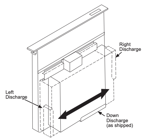
VENTING OPTIONS
- The downdraft vent is shipped with the discharge outlet pointing straight down and can be changed to the left or right side. To avoid interference problems, the downdraft vent cannot be vented to the right when installed with a GE or Monogram gas cooktop, or with a GE or Monogram non-induction electric cooktop.
- The blower outlet is sized for 3-1/4” x 10” and can be transitioned to 6” round.
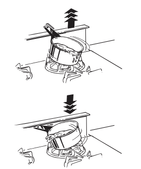
The blower is shipped with its discharge facing DOWN. Follow these steps ONLY if:
- the position of the blower discharge needs to be moved so ductwork does not interfere with floor joists, plumbing or wiring below.
- it is necessary to rotate the blower discharge to the RIGHT or LEFT.
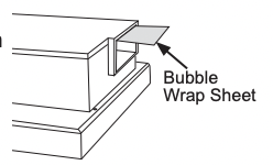
Place the unit on its back on a table or work surface.
Pull out the bubble wrap sheet. Make sure nothing is left inside.
DOWN DISCHARGE - MOVING BLOWER LEFT OR RIGHT
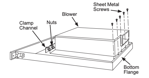
- Loosen the 4 nuts and 2 clamp channels.
- Remove the 5 screws on the bottom. These 5 screws are for shipping and do not need to be re-tightened.
- Slide blower to desired position.
- Use supplied cover plate to close open space (if any).
- Tighten wing nuts to secure top of blower and use sheet metal screws through bottom flange to secure bottom of blower.
LEFT OR RIGHT DISCHARGE
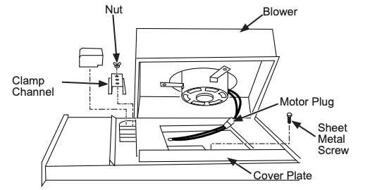
- Remove the 4 nuts and 2 clamp channels.
- Remove the 5 screws on the bottom. These 5 screws are for shipping and do not need to be re-tightened.
- Carefully lift blower and disconnect motor plug if necessary. Reposition blower and RECONNECT MOTOR PLUG.
- Use supplied cover plate to close open space (if any).
- Replace clamp channels and use nuts to secure the blower in its new position.
- Use sheet metal screws through bottom flange to secure bottom of blower.
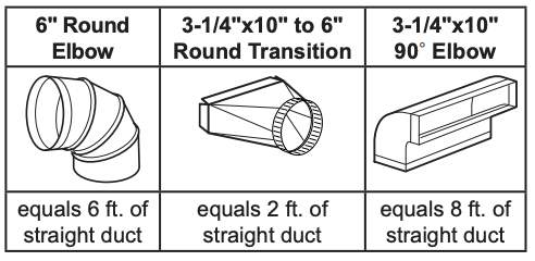
For best performance: Choose the ducting option which allows the shortest length of ductwork and a minimum number of elbows and transitions. Check location of floor joists, wall studs, electrical wiring or plumbing for possible interference.
NOTE: The unit is shipped with the 3-1/4" x 10" discharge facing DOWN. See “CHANGING BLOWER DIRECTION” on page 3, if necessary.
The system will operate most efficiently when the ductwork does not exceed 40 feet of equivalent duct. The chart, below, shows equivalent feet of elbows and transitions. The number of feet of straight duct plus the equivalent feet of transitions and/or elbows to be used should equal 40 feet or less.
Design Information
CREATIVE SOLUTIONS
- When the kitchen design calls for an against-the-wall installation, move the base cabinet forward 3” to 5”. Filler panels or complementary moldings can be added to exposed cabinet sides.
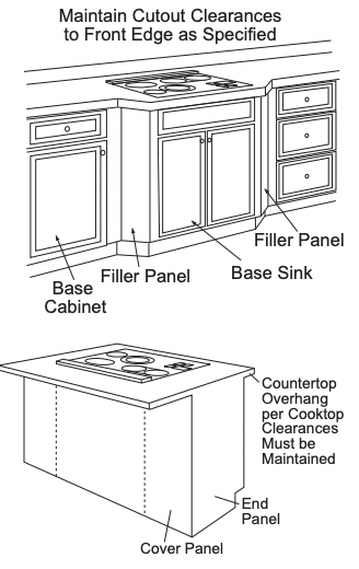
- In an island or peninsula, use an extra-deep countertop. The countertop overhang at the front can be adjusted to meet setback to cutout requirements.
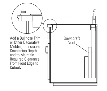
- When the cutout to the front edge of the countertop requirement is more than 2”, add a bullnose trim to the front edge of the countertop. Include the trim thickness when measuring the front edge to cutout requirement. By adding the trim, the cooktop can be moved forward,providing additional countertop depth and interior cabinet space.
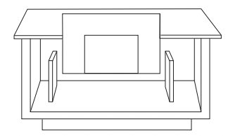
- When the distances between the vent and the inside cabinet side walls are more than 5-1/2” and/ or the inside cabinet back wall is more than 4-1/2”, false walls should be constructed inside the cabinet for securing the vent with the stabilizing brackets (refer to Cutouts and Clearances under Installation Preparation.)
PREPARING THE COUNTERTOP
Lay out and cut the cooktop cut-out far enough FORWARD so downdraft will fit behind it.
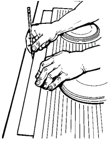
- Set cooktop in place and slide it as far forward as possible. Center and square it with edges or countertop.
- Place the plastic template against the back flange of the cooktop and center it. Trace around template to mark the downdraft opening.
3. Remove cooktop from countertop.
4. Cut downdraft opening. Be careful not to chip edges of countertop.
PREPARE FOR DUCTWORK
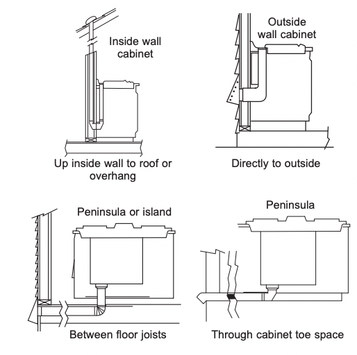
Determine the best route for ductwork; it can be routed in a variety of ways depending on the kitchen layout.
IMPORTANT: The downdraft air discharge outlet for this unit is 314” x 10” rectangular. Plan ducting accordingly.
Typical duct arrangement countertop series.
To maximize the ventilation performance of the vent system:
- Minimize the duct run length and number of transitions and elbows.
- Maintain a constant duct size.
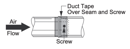
- Seal all joints with duct tape to prevent any leaks.
- Do not use any type of flexible ducting.
Optional duct arrangement under concrete slab. PVC duct should be used if installing under a poured concrete slab.
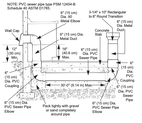
Install ductwork so the piece of duct nearest the downdraft unit slots INTO the next piece of the duct. Secure the joints with self-tapping screws and apply duct tape around the joints to ensure an airtight seal.
Installation Instructions
1. MOUNT THE UNIT
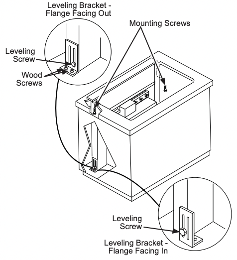
A. Set downdraft into opening. Extend leveling brackets to floor of cabinet so downdraft sits straight. (NOTE: Leveling brackets can be removed and re-attached in other positions. Bottom flange may have to face inward in tight cabinet installations.)
B. Secure the downdraft to the countertop as follows: Hold the downdraft against the back of countertop cut-out and tighten the 2 mounting screws (one on each end of unit) on underside of countertop. Use a shim between screw and underside of granite countertops.
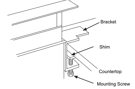
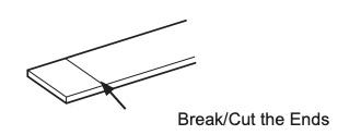
The ends of the template may be broken or cut and used as shims if required.

C. Screw leveling brackets to bottom of cabinet using the four wood screws (provided with the unit) on each side.
D. Tighten leveling screws through leveling bracket slots to the unit on each side.
E. Place cooktop into the countertop cutout. There should be 1/8" minimum gap between the front of the vent trim and the rear of the cooktop.
F. Connect duct. Use a roof or wall cap (with damper) that is intended for use with kitchen hoods and vent systems.
2. CONNECT POWER
Plug power cord into properly grounded receptacle.
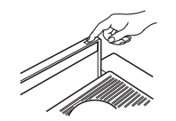
3. INSTALL FILTERS, CHECK OPERATION
- Press the button on the top cover to raise the vent.
- Lift the vent straight up and pull forward.
- Slide filter into the retainers and close the vent.
- Turn the knob on the right side of the air vent to start the blower and adjust the speed.
- To lower the vent, press the button on the top cover.
NOTE: It is not necessary to turn the fan OFF before lowering the vent. The fan will automatically turn off when the vent is lowered. When the fan is not turned off before lowering the vent, it will automatically come on at the previously set speed when the vent is fully raised.
TROUBLESHOOTING TIPS
Save time and money! Review the charts on the following pages first and you may not need to call for service.
| Problem |
Possible Cause |
What To Do |
| Fan does not work |
The vent is not fully extended. |
Press the button on the top cover. |
Vent does not work
|
The vent is not plugged into an outlet. |
Plug the vent into a 120V power outlet. |
| The button did not engage the lift motor. |
Hold down the button for a couple of seconds to activate the motor. |
| The circuit breaker may have tripped. |
Check the circuit breaker— reset if necessary |
| Sufficient makeup (replacement) air is required for exhausting appliances to operate to rating. |
Check with local building codes, which may require or strongly advise the use of makeup air. Visit GEAppliances for available makeup air solutions. |