Loading ...
Loading ...
Loading ...
45
DIAGNOSTIC CHART
The logic board has several LEDs to assist in the installation and troubleshooting of the operator. The following chart should assist in
verifying the operator is functioning properly. Turn the selector dial to DIAG to keep the door from moving while troubleshooting.
TROUBLESHOOTING
Troubleshooting
RADIO Amber: Refer to page 48 for RADIO LED codes.
** RESTRICTED CLOSE. This method will allow a door to be closed using the operator when LMEP Device(s) are no longer working.
Press and hold the CLOSE button until the door reaches the closed limit. If the CLOSE button is released before the door reaches the
closed limit the operator will stop and the procedure will need to be repeated to fully close the door.
LED COLOR DEFINITION
Power Green Indicates power is being generated for the logic board.
Stop Green Indicates a closed circuit between common and terminal 5. Pressing the stop button should turn off this LED.
Open Yellow Indicates a closed circuit between common and terminal 7. Pressing the open button should turn on this LED.
Close Yellow Indicates a closed circuit between common and terminal 6. Pressing the close button should turn on this LED.
LMEP Green A solid illuminated LED indicates the LMEP is learned and operational. Flashing indicates sensors are
obstructed, a wiring issue exists, or the LMEP Device(s) have been removed.**. Solid off indicates no sensors learned.
Timer Defeat Yellow Solid on indicates a closed circuit between common and terminal 12. Timer-To-Close will not close.
OLS Yellow Pressing the Open Limit Switch should turn on this LED. Indicates the Open Limit Switch is activated.
CLS Yellow Pressing the Close Limit Switch should turn on this LED. Indicates the Close Limit Switch is activated.
SLS Yellow Pressing the Sensing Limit Switch should turn on this LED. Indicates the Sensing Limit Switch is activated.
Edge Yellow Indicates a closed circuit between common and terminal 8. Pressing the Edge should turn this LED on.
Mid-Stop Yellow A solid illuminated LED indicates the door is stopped on up Mid-Stop. Flashing indicates Mid-Stop is being set.
Timer Enabled Green A solid illuminated LED indicates the TIMER is programmed and will activate from the Open or Mid-Stop positions.
Flashing indicates the Timer is counting down and the door will close after the programmed preset time. Each flash
represents 1 second of programmed time.
SBC Yellow Indicates a closed circuit between common and terminal 1. Pressing the Single Button Control Station should turn
this LED on.
MAS Yellow Indicates the Maintenance Alert System has been activated or an error code has been triggered.
Relay A Yellow Indicates an OPEN or CLOSE command has been given to the motor. LED turns on when either the OPEN or CLOSE
buttons are pressed.
Relay B Yellow Indicates an OPEN or CLOSE command has been given to the motor. LED turns on when either the OPEN or CLOSE
buttons are pressed.
DATA Green Indicates communication between the Logic Board and optional TLS1CARD.
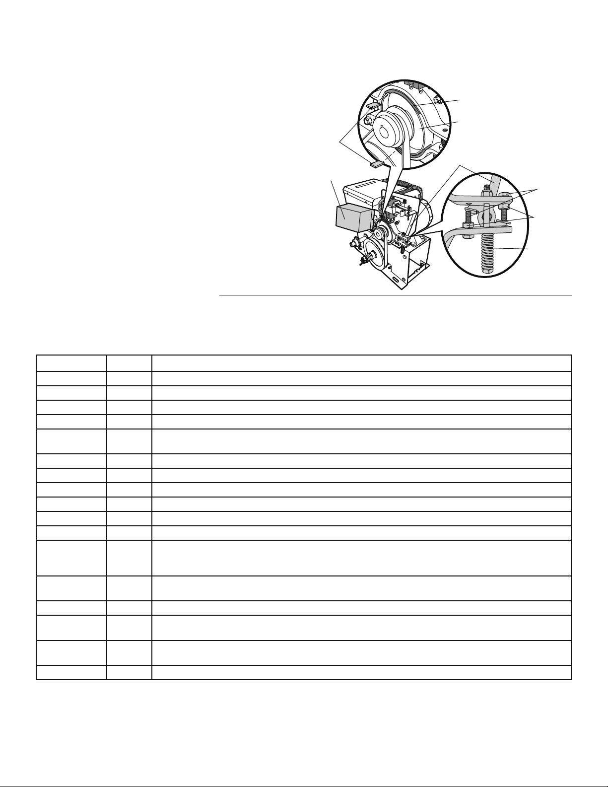
BRAKE
A drum brake comes standard on T, H, J, and HJ model operators with 3/4HP and larger motors. It comes adjusted from the factory,
however, occasional adjustments may be necessary throughout the life of the brake.
ADJUSTING DRUM BRAKE:
1. Manually activate the brake by holding back brake lever and
insert a type of shim (a business card or a folded piece of
paper work well) between the brake pad and brake drum as far
away from the spring bolt as possible, while still inserting
between the brake pad and drum. Release the brake lever. This
will create the necessary space to ensure the brake is not
dragging when the door is in motion.
2. Tighten both stop bolts until the bolts come into contact with
the lever. Secure the stop bolts in place by tightening the stop
bolt nuts. Remove the shim used in step 1.
3. Tighten or loosen the spring bolt to add or release brake force.
4. Connect power to the operator. Run the operator and ensure
the brake is working properly.
5. Make any adjustment necessary. If the solenoid buzzes while
running, loosen the spring bolt until the buzzing is no longer
present when the operator is in motion. A buzzing solenoid will
stress the solenoid and can cause it to fail prematurely.
Brake Pad
Brake Drum
Spring Bolt
Stop Bolts
Stop Bolts
Nuts
Brake Lever
Solenoid Cover
Shims
Loading ...
Loading ...
Loading ...