Part Number 1955203 rev 4 4/15
Installation, Operation and Maintenance Manual
This manual is updated as new information and models are released. Visit our website for the latest manual.
Master Series
Full-Size Electric Convection Ovens
models
MCO-ES-10S
MCO-ED-10S
MCO-ES-20S
MCO-ED-20S
MCO-ES-10
MCO-ED-10
MCO-ES-20
MCO-ED-20
MCO-ES-10

Part Number 1955203 rev 4 4/152
Users are cautioned that maintenance and repairs must be performed by a Garland authorized service agent
using genuine Garland replacement parts. Garland will have no obligation with respect to any product that has been
improperly installed, adjusted, operated or not maintained in accordance with national and local codes or installation
instructions provided with the product, or any product that has its serial number defaced, obliterated or removed,
or which has been modified or repaired using unauthorized parts or by unauthorized service agents.
For a list of authorized service agents, please refer to the Garland web site at http://www.garland-group.com.
The information contained herein, (including design and parts specifications), may be superseded and is subject
to change without notice.
FOR YOUR SAFETY:
DO NOT STORE OR USE GASOLINE
OR OTHER FLAMMABLE VAPORS OR
LIQUIDS IN THE VICINITY OF
THIS OR ANY OTHER
APPLIANCE
WARNING:
IMPROPER INSTALLATION, ADJUSTMENT,
ALTERATION, SERVICE OR MAINTENANCE
CAN CAUSE PROPERTY DAMAGE, INJURY,
OR DEATH. READ THE INSTALLATION,
OPERATING AND MAINTENANCE
INSTRUCTIONS THOROUGHLY
BEFORE INSTALLING OR
SERVICING THIS EQUIPMENT
PLEASE READ ALL SECTIONS OF THIS MANUAL
AND RETAIN FOR FUTURE REFERENCE.
THIS PRODUCT HAS BEEN CERTIFIED AS
COMMERCIAL COOKING EQUIPMENT AND
MUST BE INSTALLED BY PROFESSIONAL
PERSONNEL AS SPECIFIED.
INSTALLATION AND ELECTRICAL CONNECTION
MUST COMPLY WITH CURRENT CODES:
IN CANADA - THE CANADIAN ELECTRICAL
CODE PART 1 AND / OR LOCAL CODES.
IN USA – THE NATIONAL ELECTRICAL CODE
ANSI / NFPA – CURRENT EDITION.
ENSURE ELECTRICAL SUPPLY CONFORMS WITH
ELECTRICAL CHARACTERISTICS SHOWN ON
THE RATING PLATE.
SAFETY NOTICES
WARNING:
This product contains chemicals known to the state of California to cause cancer and/or birth defects or other
reproductive harm. Installation and servicing of this product could expose you to airborne particles of glass wool/
ceramic fibers. Inhalation of airborne particles of glass wool/ceramic fibers is known to the state of California to cause
cancer.
Notice: CE models discontinued (manufactured up to October, 2014).
Power Failure
In the event of a power failure, no attempt should be
made to operate this oven.

Part Number 1955203 rev 4 4/15 3
TABLE OF CONTENTS
SAFETY NOTICES. . . . . . . . . . . . . . . . . . . . . . . 2
GENERAL INFORMATION . . . . . . . . . . . . . . . 5
Model Numbers . . . . . . . . . . . . . . . . . . . . . . . . . . . . . 5
Warranty . . . . . . . . . . . . . . . . . . . . . . . . . . . . . . . . . . . . 5
Serial Plate Location . . . . . . . . . . . . . . . . . . . . . . . . . . 5
Accessories . . . . . . . . . . . . . . . . . . . . . . . . . . . . . . . . . . 5
DIMENSIONS AND SPECIFICATIONS, MCO
ED/ES 10/20 . . . . . . . . . . . . . . . . . . . . . . . . . . . 6
DIMENSIONS AND SPECIFICATIONS, MCO
ED/ES 10/20 S. . . . . . . . . . . . . . . . . . . . . . . . . . 7
INSTALLATION . . . . . . . . . . . . . . . . . . . . . . . . . 8
Entry Clearance . . . . . . . . . . . . . . . . . . . . . . . . . . . . . . 8
Installation Clearance . . . . . . . . . . . . . . . . . . . . . . . . 8
Installation of Double Deck Models . . . . . . . . . . . 8
Electrical Connections . . . . . . . . . . . . . . . . . . . . . . . . 9
OPERATING INSTRUCTIONS. . . . . . . . . . . . 10
Master 200 Solid State Control with
Electromechanical Timer . . . . . . . . . . . . . . . . . . . 10
Modes . . . . . . . . . . . . . . . . . . . . . . . . . . . . . . . . . . 10
Fan Speed . . . . . . . . . . . . . . . . . . . . . . . . . . . . . . 10
Lights. . . . . . . . . . . . . . . . . . . . . . . . . . . . . . . . . . . 10
Cool Down. . . . . . . . . . . . . . . . . . . . . . . . . . . . . . 10
Temperature . . . . . . . . . . . . . . . . . . . . . . . . . . . . 10
Timer . . . . . . . . . . . . . . . . . . . . . . . . . . . . . . . . . . . 11
Master 450 Electronic Control with
Cook-N-Hold and Master 455 Electronic Control
with Cook-N-Hold & Core Probe . . . . . . . . . . . . . 11
Modes . . . . . . . . . . . . . . . . . . . . . . . . . . . . . . . . . . 11
Controller Keys . . . . . . . . . . . . . . . . . . . . . . . . . . 11
Fahrenheit/Celsius. . . . . . . . . . . . . . . . . . . . . . . 12
Operating the Controls . . . . . . . . . . . . . . . . . . 13
Cook-N-Hold Operation . . . . . . . . . . . . . . . . . 13
Core Probe Operation . . . . . . . . . . . . . . . . . . . 13
Setting Setback Feature . . . . . . . . . . . . . . . . . 13
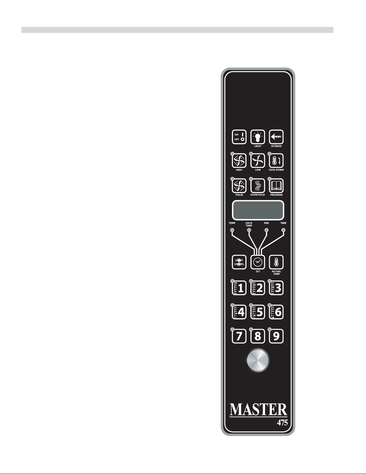
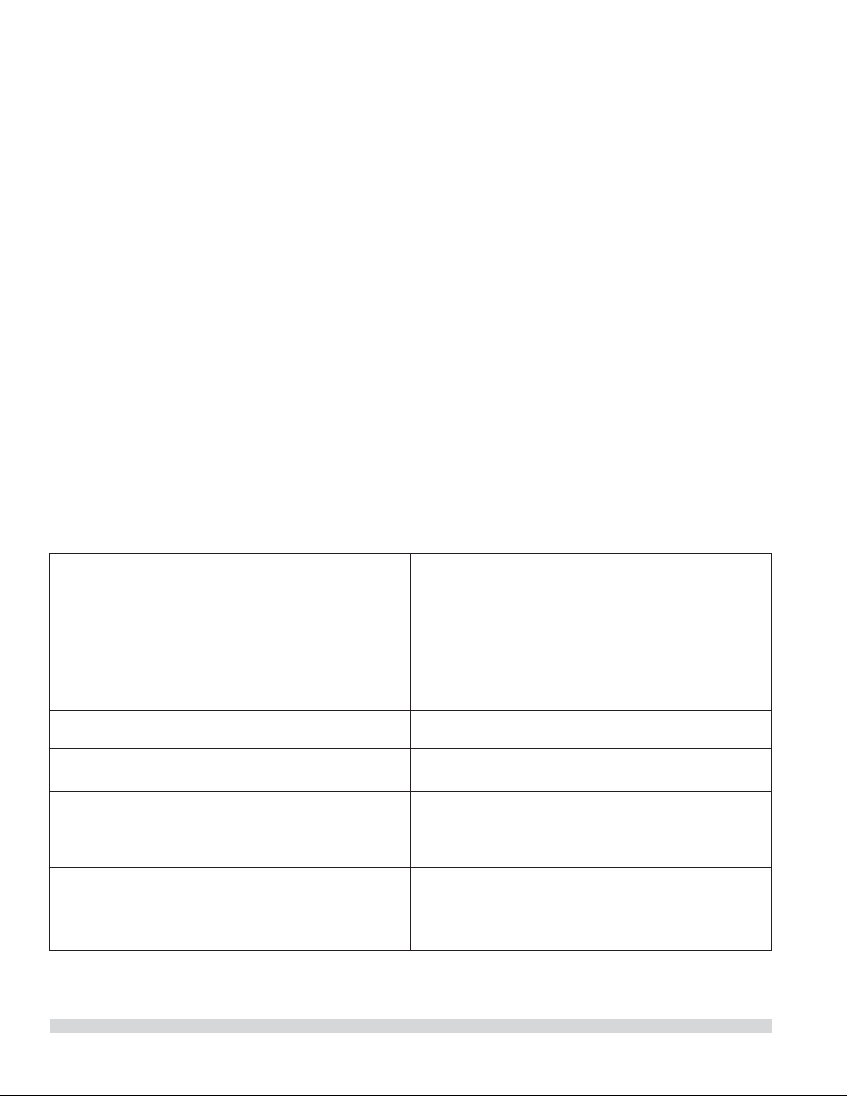
Master 475 Electronic Programmable Control 14
Manual Cooking. . . . . . . . . . . . . . . . . . . . . . . . . 14
Manual cooking using Cook-N-Hold. . . . . . 14
Programming Product Keys (Master 475) . 14
Cooking Using The Product Keys
(Master 475). . . . . . . . . . . . . . . . . . . . . . . . . . . . . 15
Verifying Hold Time (Master 475). . . . . . . . . 16
Selecting Fahrenheit or Celsius (Master 475) . . 16
Cooking With The Shelf Timer (Master 475) . .
16
PERFORMANCE RECOMMENDATIONS AND
GENERAL SAFETY PRECAUTIONS. . . . . . . 17
PROBLEM/SOLUTIONS . . . . . . . . . . . . . . . . 18
COOKING GUIDE . . . . . . . . . . . . . . . . . . . . . . 19
COOK AND HOLD . . . . . . . . . . . . . . . . . . . . .20
CLEANING AND MAINTENANCE . . . . . . . . 21
Break-In Period . . . . . . . . . . . . . . . . . . . . . . . . . . . . . 21
Exterior Cleaning . . . . . . . . . . . . . . . . . . . . . . . . . . . 21
Interior Cleaning . . . . . . . . . . . . . . . . . . . . . . . . . . . . 21
Fan Area Maintenance . . . . . . . . . . . . . . . . . . . . . . 21
Motor Care . . . . . . . . . . . . . . . . . . . . . . . . . . . . . . . . .21

THIS PAGE INTENTIONALLY LEFT BLANK
Part Number 1955203 rev 4 4/15 5
GENERAL INFORMATION
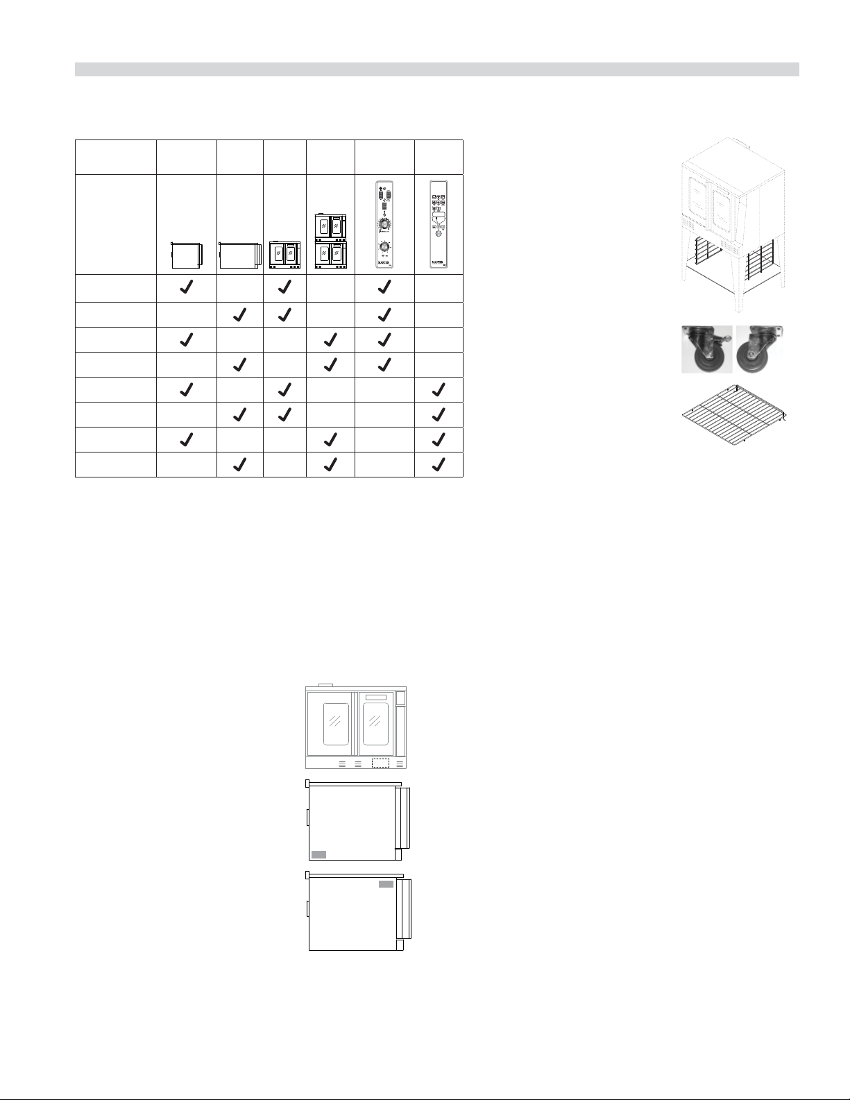
Model Numbers
Model Standard
Depth
Deep
Depth
Single
Deck
Double
Deck
Master
200
Control
Digital
Control
MCO-ES-10S
MCO-ED-10S
MCO-ES-20S
MCO-ED-20S
MCO-ES-10
MCO-ED-10
MCO-ES-20
MCO-ED-20
Warranty
Visit www.Garland-Group.com to view or download a copy of your
warranty.
Serial Plate Location
When corresponding with the factory or your local authorized
factory service center regarding service problems or replacement
parts, be sure to refer to the particular unit by the correct model
number (including the prefix and suffix letters and numbers) and
the warranty serial number.
Ovens Built prior to 31-MAR-2011
• The serial plate is affixed to the
inside of the lower front cover.
Ovens Built between 01-APR-2011
and
• The serial plate is affixed to the
lower left corner of the left body
panel.
Ovens Built after 02-FEB-2015
• The serial plate is affixed to the
upper right corner of the left
body panel.
Accessories
• Stainless steel open base
with rack guides and shelf
(in lieu of 25-inch legs) for
extra rack/pan storage,
single deck oven only
• Swivel Casters (set of 4) with
front brakes
• Extra oven rack
• Removable stainless steel drip pan
Part Number 1955203 rev 4 4/156
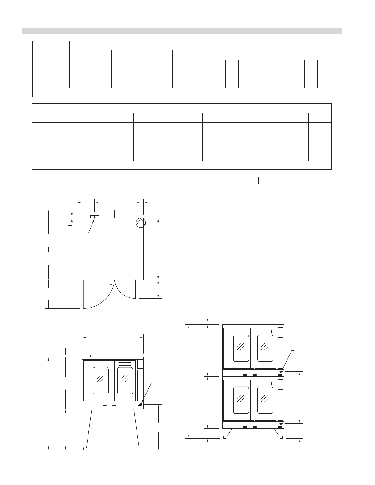
DIMENSIONS AND SPECIFICATIONS, MCO ED/ES 10/20
7-3/4"
[197mm]
MCO-ES
41-1/4"
[1048mm]
MCO-ED
44-1/2"
[1130mm]
38-1/4"
[972mm]
3/4"
[19mm]
17-3/4"
[451mm]
TOP VIEW
38"
[965mm]
32-1/8"
[816mm]
57-1/2"
[1461mm]
25-3/8"
[645mm]
SINGLE DECK
FRONT VIEW
1-1/4"
[32mm]
32-1/8"
[816mm]
32-1/8"
[816mm]
70-1/2"
[1791mm]
6-1/4"
[159mm]
1-1/4"
[32mm]
DOUBLE DECK
FRONT VIEW
FLUE: 2-3/8" x 5"
[60mm x 127mm]
REAR
CABLE
ENTRANCE
REAR CABLE
ENTRANCE
11-1/2"
[292mm]
1-11/16"
[43mm]
28-3/8"
[721mm]
32-1/8"
[816mm]
9-1/4"
[235mm]
Model**
Total
kW
Load
Nominal Amperes Per Line (includes 3/4 HP fan motor)
208V/
1Ph
240V/
1Ph
208V/3Ph 240V/3Ph 460V/3Ph 380V/3Ph** 415V/3Ph
XYZXYZXYZXYZXYZ
MCO-ES-10 10.4 50 43 30 30 28 26 26 24 14 14 13 15 13 13 16 14 14
MCO-ED-10 10.4 50 43 30 30 28 26 26 24 14 14 13 15 13 13 16 14 14
**Total kW rating for 380/3 phase models is 9.0
Model
Interior Dimensions (per oven) Exterior Dimensions Ship Info.
W:In(mm) H:In(mm) D:In(mm) W:In(mm) H:In(mm) D:In(mm) Lbs./Kg Cu. Ft.
MCO-ES-10 29 (736) 24 (610) 24 (610) 38 (965) 57-1/2 (1461) 41-1/4 (1048) 515/230 64
MCO-ES-20 29 (736) 24 (610) 24 (610) 38 (965) 70-1/2 (1791)* 41-1/4 (1048) 1030/465 128
MCO-ED-10 29 (736) 24 (610) 28 (711) 38 (965) 57-1/2 (1461) 44-1/2(1130) 545/245 64
MCO-ED-20 29 (736) 24 (610) 28 (711) 38 (965) 70-1/2 (1791)* 44-1/2(1130) 1090/490 128
* Height with legs or with standard casters. Height with low profile casters (double deck) is 68-1/2” (1740mm).
Standard electrical speci cations include motor
requirements. 3/4 HP, 2-speed motor, 1140/950 and
1725/1140 RPM, 60/50 Hz.
NOTE: Double deck ovens are provided with individual
supply connections.
Notice: CE models discontinued (manufactured up to October, 2014).
Part Number 1955203 rev 4 4/15 7
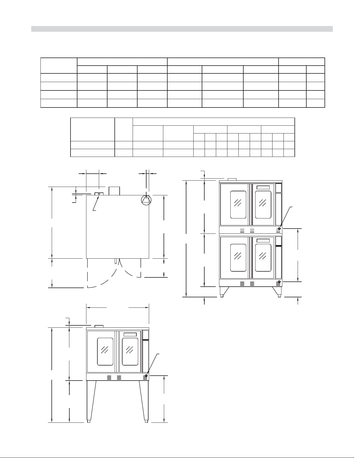
DIMENSIONS AND SPECIFICATIONS, MCO ED/ES 10/20 S
7-3/4"
[197mm]
38-1/4"
[972mm]
3/4"
[19mm]
17-3/4"
[451mm]
TOP VIEW
38"
[965mm]
32-1/8"
[816mm]
25-3/8"
[645mm]
SINGLE DECK
FRONT VIEW
1-1/4"
[32mm]
32-1/8"
[816mm]
32-1/8"
[816mm]
6-1/4"
[159mm]
1-1/4"
[32mm]
DOUBLE DECK
FRONT VIEW
FLUE: 2-3/8" x 5"
[60mm x 127mm]
11-1/2"
[292mm]
28-3/8"
[721mm]
REAR CABLE
ENTRANCE
1-11/16"
[43mm]
9-1/4"
[235mm]
32-1/8"
[816mm]
REAR CABLE
ENTRANCE
D
H
H
Standard electrical speci cations include motor
requirements. 3/4 H.P., 2 speed motor, 1140/950
and 1725/1140 RPM, 60/50 Hz.
Model
Interior Dimensions (per oven) Exterior Dimensions Ship Info.
W:In(mm) H:In(mm) D:In(mm) W:In(mm) H:In(mm) D:In(mm) Lbs./Kg Cu Ft
MCO-ES-10S
29(436) 24(610) 24(610) 38(965) 57-1/2(1416)
41-1/4 (1048)
515/230 64
MCO-ES-20S
29(436) 24(610) 24(610) 38(965) 70-1/2(1791)*
41-1/4 (1048)
1030/465 128
MCO-ED-10S
29(436) 24(610) 28(711) 38(965) 57-1/2(1416)
44-1/2(1130)
545/245 64
MCO-ED-20S
29(436) 24(610) 28(711) 38(965) 70-1/2(1791)*
44-1/2(1130)
1090/490 128
* Height with or without standard casters. Height with low pro le casters (double deck) is 68-1/2" (1740mm).
Model**
Total
kW
Load
Nominal Amperes Per Line (includes 3/4 HP fan motor)
208V/1Ph 240V/1Ph
208V/3Ph 240V/3Ph 460V/3Ph
XYZXYZXYZ
MCO-ES-10S 10.4 50 43 30 30 28 26 26 24 14 14 13
MCO-ED-10S 10.4 50 43 30 30 38 26 26 24 14 14 13
** NOTE: Double deck ovens are provided with individual supply connections

Part Number 1955203 rev 4 4/158
INSTALLATION
Entry Clearance
• Crated: 47” (1194mm)
• Uncrated: 32-1/2” (826mm)
Installation Clearance
NOTE: Always provide adequate clearance for maintenance
and operation.
• Installation adjacent to combustible and non-
combustible wall, minimum clearance:
Left Side Control Side Rear
Single-Deck 1" (26 mm) 1" (26 mm) 3" (77 mm)
Double-Deck 1" (26 mm) 2" (51 mm) 3" (77 mm)
• Installation near high heat producing equipment,
minimum clearance:
Left Side Control Side Rear
Single-Deck 1" (26 mm) 6" (153 mm) 3" (77 mm)
Double-Deck 1" (26 mm) 6" (153 mm) 3" (77 mm)
Notice
Avoid installing ovens near equipment, such as char-
broilers or fryers, which generate high heat and high
grease laden air.
• Clearance for Service (recommendation):
Control Side, minimum
Single-Deck 12" (305 mm)
Double-Deck 12" (305 mm)
NOTE: Install units with casters in very tight
locations for ease of service.
IMPORTANT Large objects should not be placed in front
of this oven, which would obstruct the air ow through the
front. Objects should not be placed on the main top rear
of the oven while in use because this could obstruct the
venting system. Install ovens where side body perforated
panels or control sections do not get sprayed with water
wash down spray hoses.
Installation of Ovens Equipped with Casters
A. For an appliance equipped with casters, the installation
shall be made with a connector that complies with the
Standard for Connectors for Movable Appliances, ANSI
Z21.69. Adequate means must be provided to limit the
movement of the appliance without depending on the
connector wiring.
B. The front casters of the unit are equipped with brakes to
limit the movement of the oven without depending on
the connector wiring to limit the appliance movement.
C. A restraint can be attached to the unit. If the restraint is
disconnected, be sure to reconnect the restraint after the
oven has been returned to its originally installed position.
Installation of Double Deck Models
A. Position insert in bottom leg opening and tap insert up
into leg until it seats at collar. Attach six inch (6”) legs to
lower oven section. Raise unit or lay on its left side. Place
the front legs on the oven so as to line up with four (4)
attaching bolt holes. Secure leg to oven frame using (4)
3/8-16 x 3/4 bolts and washers provided. Repeat at rear of
unit.
B. Remove lower front cover of top deck (located under
oven doors). Raise top deck into place and line up body
sides and back of the unit. Fasten the rear of the units
together, with the stacking bracket using (6) 1/4-20
machine screws, lock washers and nuts, (provided).
C. Install the interconnecting ue parts, carefully following
the instructions contained in the stacking kit. Pay
particular attention to the type of ovens you are stacking
and be sure to follow the corresponding instructions.
D. Check leveling of unit four (4) ways (using a common
carpenter’s level on the rack inside the oven).
E. Maintain clearance from combustibles.
CAUTION: Disconnect both ovens from electrical supply
before servicing to protect against shock!
Part Number 1955203 rev 4 4/15 9
Electrical Connections
Before attempting the electrical connection, the rating
plate should be checked to ensure that the unit’s electrical
characteristics and the supply electrical characteristics agree.
Installation of the wiring must be made in accordance with
U.L. 197 Commercial Electric Cooking Appliance Standards,
Local and/or National Electrical Code,
ANSI/NFPA 70-1990, or the Canadian Electrical Code, CSA
C22.2 as applicable.
1. Switch panel size
2. Overload protection
3. Wire type
4. Wire size
5. Temperature limitations of the wires
6. Method of connection (Cable, Conduit, etc.)
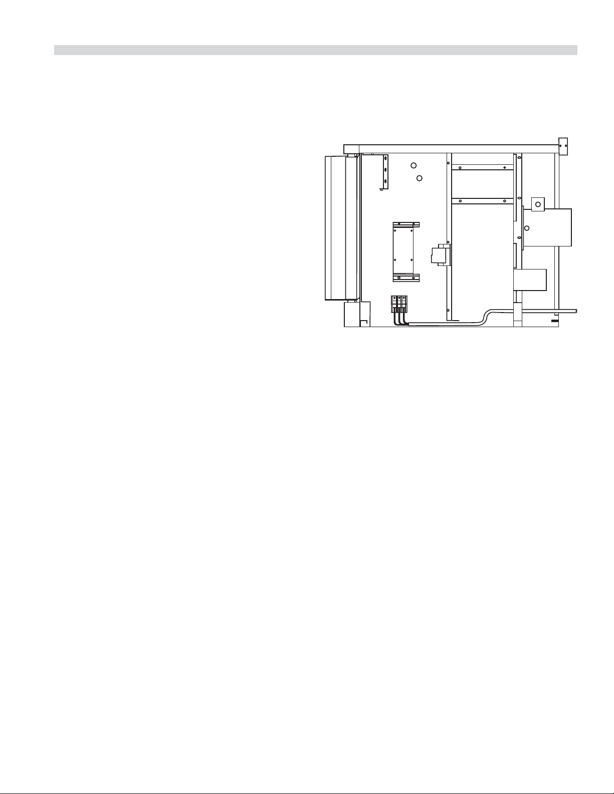
The service line will enter through the rear of the unit and
is to be connected to the terminal block (see diagram). The
terminal block is accessed by removing the lower front cover.
Removal of the body side is not necessary. Install a main
disconnect switch and a separate fuse or breaker with this
appliance. Use a su cient length of exible conduit between
the main disconnect switch and the appliance so unit can be
moved for service.
Input voltage and phasing must match the units voltage
and phasing. Wiring diagram is attached to the main back of
each oven. Visually check all electrical connections. Energize
electric service to units.
The oven is wired per original factory order. If it is necessary
to change to single-phase or three-phase, please refer to kit
part number 4533009.
Service and unit voltage must agree.
INSTALLATION Continued
Part Number 1955203 rev 4 4/1510
OPERATING INSTRUCTIONS
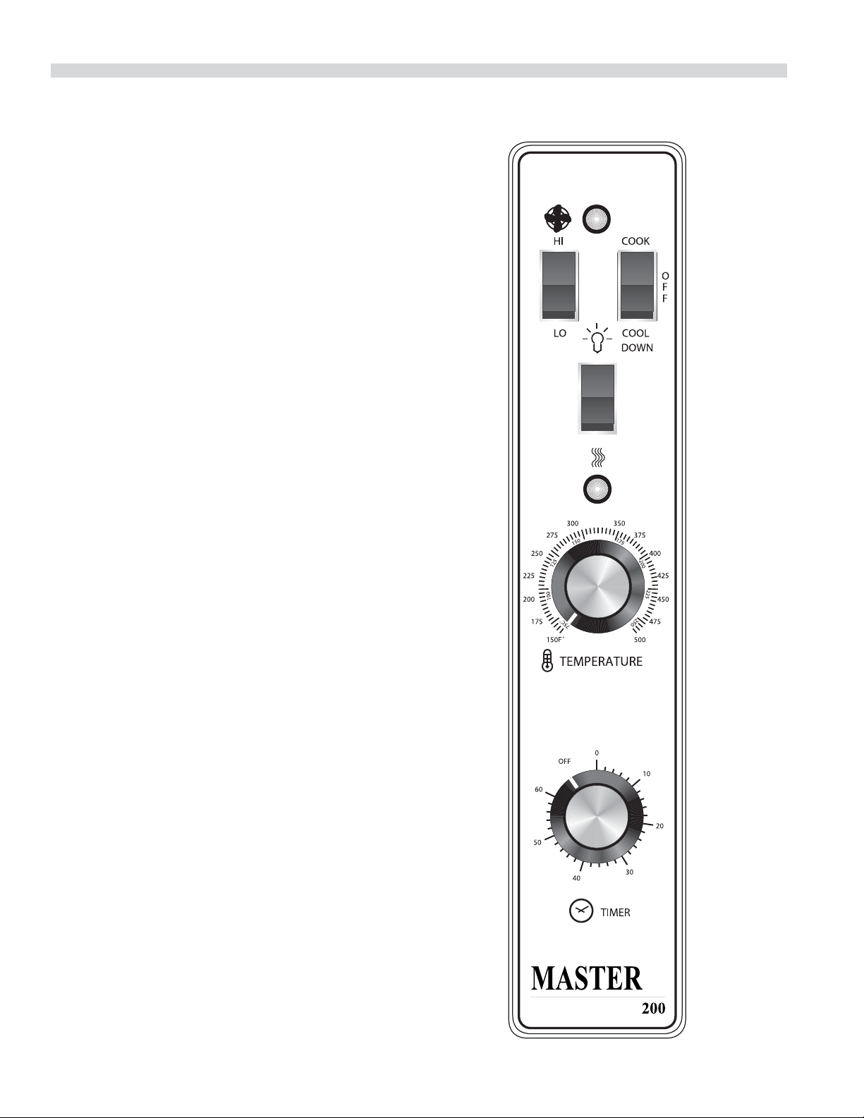
Master 200 Solid State Control with
Electromechanical Timer
Modes
In O Mode
When the oven is o , there are no lights or indicators.
Start Up
Press the COOK/OFF/COOL DOWN rocker switch to the
“COOK” position. The green lamp will light indicating the
oven is powered in cook mode.
The oven will begin to heat to the temperature set on the
thermostat dial. The amber lamp will light indicating the heat
is active. As the heat cycles on and o to maintain the set
temperature this light will go on and o accordingly.
The door must be closed for the oven to operate in cook
mode. Opening the door will cause the heat to stop and the
motor and fan will shut o . This is a safety feature.
Fan Speed
The fan speed can be either high (1725RPM) or (1150RPM).
The fan speed is controlled by the left rocker switch marked
high and low.
Lights
The oven lights are activated by pressing the light switch
on the control panel. This is a momentary switch and the
lights will stay lit as long as this button is held in the on
position. Lights will work whenever there is electrical power
connected to the oven.
Cool Down
Pressing the COOK/OFF/COOL down rocker switch to the
COOL DOWN position activates the fan and motor to cool
the oven cavity. The door must be open slightly for the fan
and motor to start. The heat is not active in this mode.
Optimal cool down will be achieved with the door open
slightly. Opening the door too far will shut the fan and motor
o . This is a patented safety feature.
Pressing the button to the OFF position cancels the cool
down and turns the oven o .
Temperature
The temperature range is from 150° to 500°F (66°C) to 250°C)
is controlled by rotating the temperature dial and aligning
the indicator to the desired temperature.
Part Number 1955203 rev 4 4/15 11
Timer
The timer is set by rotating the dial clockwise aligning the
indicator to the desired time cycle. The timer will count down
from 2 minutes to 60 minutes. At the end of the timing cycle
the buzzer will sound. The buzzer is turned o by rotating the
dial counter-clockwise to the o position.
NOTE: The timer does not control heating.
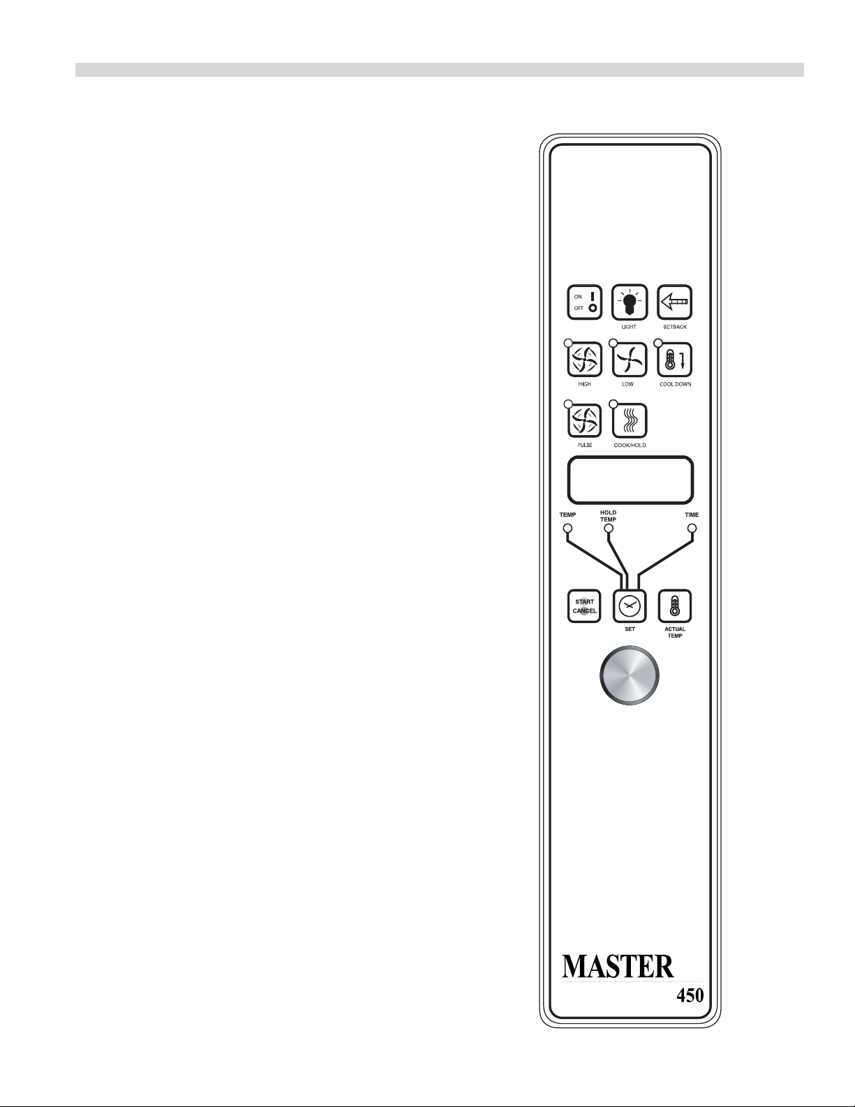
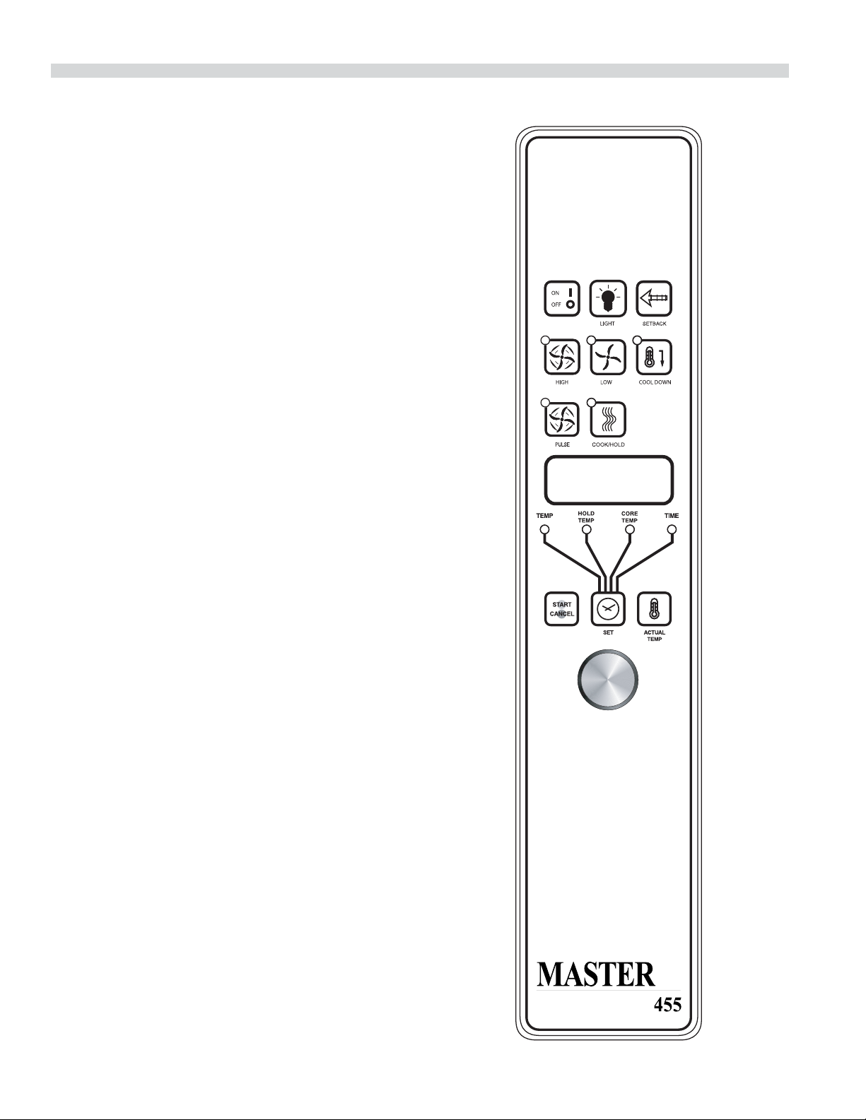
Master 450 Electronic Control with
Cook-N-Hold and Master 455 Electronic
Control with Cook-N-Hold & Core Probe
Modes
In O Modes
When the controller is o , the display will show “OFF”.
Pressing the ON/OFF key will activate the controller into
Start Up Mode.
Start Up
In Start Up mode, the controller will heat to the last set
temperature, time and fan speed. The factory defaults are
350°F (177°C), 30 minutes and low fan speed. The display will
indicate “LO” when the oven is below the set temperature.
When the oven cavity reaches the set temperature and is
ready for operation the display will indicate “LOAD”.
NOTE: If the oven temperature goes above the requested
temperature the display will indicate “HI” If the oven
temperature goes above 575°(302°C) the display will indicate
“HELP” and an audible signal will sound. This is a safety
feature.
If the door is opened during a cooking mode, the fan and
heat will stop, and the display will indicate “DOOR” until the
door is closed. This is a patented safety feature.
Pressing the ACTUAL TEMP key will display the actual oven
temperature in 5° increments.
Controller Keys
Pressing the ON/OFF key will activate the oven.
Pressing the LIGHT key will turn the lights on for 30 seconds.
The lights will work if the controller is in the O mode. When
the door is opened, the light will come on and stay on for 30
seconds.
OPERATING INSTRUCTIONS Continued
Part Number 1955203 rev 4 4/1512
Pressing the FAN HIGH key will activate the higher fan speed
and light its LED.
Pressing the FAN LOW key will activate the lower fan speed
and light its LED.
Pressing the FAN PULSE key will activate the lower fan speed
and light its LED. The fan will be active for 30 seconds then
o for 30 seconds, and continuous this cycle.
Pressing the SETBACK key will cool the oven cavity to
a preprogrammed temperature, see: Setting “Set-Back”
Feature. The oven will automatically go into Setback mode
after the pre-programmed non-usage time. The display will
indicate “SETB”. This is an energy-saving feature.
Pressing the COOL DOWN key will deactivate the heat, turn
the fan on high and light its LED. This display will indicate
“OPEN DOOR” if the door is closed, prompting the user
to open the door slightly. With the door open slightly the
display will indicate “COOL”. The Cool down will operate
when the door is closed or opened slightly. Optimal cool-
down will be achieved with the door open slightly. When
the door opens wider, the Cool Down mode will deactivate
and the display will indicate “DOOR”. This is a patented safety
feature. Pressing the COOL DOWN key again will turn the
LED o and stop this mode. Pressing the ON/OFF key will
also cancel Cool down. Cool Down is not active during a
cook.
When the ON/OFF switch is pressed to turn the oven o and
the oven was above 200°F (93°C), the oven will go into an
AUTO COOL DOWN mode. In Auto cool Down, the oven will
run the fan on high until the oven cavity drops below 150°F
(66°C). During this time the display will indicate “AUTO”.
When the oven temperature drops below 150°F (66°C) the
oven turns o . This feature protects the oven motor from
premature failure. Optimal cool-down will be achieved with
door open slightly.
Fahrenheit/Celsius
Factory default is Fahrenheit (F). To change to
Celsius (C), press and hold in the “Phantom Key” located
to the right of “Cook/Hold” key. “F” appears in the display.
Continue to hold until “C” is displayed and then release the
“Phantom key”.
OPERATING INSTRUCTIONS Continued

Part Number 1955203 rev 4 4/15 13
Core Probe Operation
The Core Probe option (455 Controller Only) is only active
when the core probe is plugged into its connector. To set the
core temperature, rst plug the core probe into its connector.
The display will indicate “100” and the CORE TEMP LED will
be on. The operator then sets the temperature by rotating
the dial on the controller until the desired temperature is
shown on the display. Pressing the SET key stores the core
temperature and starts the cooking process.
To set the oven temperature, press the SET key again. The
TEMP LED will light and the oven temperature can be
set by rotating the dial on the controller until the desired
temperature is displayed. Pressing the SET key again will
light the HOLD LED allowing the operator to set the hold
temperature in the same manner.
NOTE: If the hold temperature is not set, the default
hold temperature is 150°F (66°C) or the last programmed
temperature. (Hold temperature range is 140°F (60°C) to
210°F (99°C).
When the core temperature is reached the display will sound
and ash “DONE” for 3 seconds. Automatically, the display
will switch to count “UP” the time the oven is on hold.
Setting Setback Feature
To set or change the setback settings, press and hold the
SETBACK key for two seconds. The TEMP LED will light and a
temperature will be displayed. Set the temperature using the
dial, then press the SET key. The TEMP LED will go out and
the TIME LED will light (“Time” is factory set at 0). Set the time
using the dial, then press the SET key. Press the SET key one
more time to exit programming.
Note: To disable the setback function, set the temperature to
250º F (121ºC) and the time to zero.
Operating the Controls
Setting the cook temperature and time are done in the same
manner. Pressing the SET key will light the TEMP LED. The
operator then sets the temperature by rotating the dial on
the controller until the desired temperature is shown on the
display. Pressing the SET key a second time lights the TIME
LED and allows the operator to select the desired cook time
as shown on the display. Pressing the SET key a third time
ends the programming.
Pressing the START/CANCEL key will start the timing cycle.
The display will count down from the Set time in minutes and
seconds (solid colon) or hours and minutes (blinking colon)
then minutes and seconds. When the cycle is completed,
pressing this key will also cancel the “DONE” prompt. To
cancel a timing cycle in progress, press and hold the START/
CANCEL key for 3 seconds.
Cook-N-Hold Operation
Pressing the COOK/HOLD (450 and 455 Controllers Only) key
activates the Cook-N-Hold mode and lights is LED. To verify
the proper hold temperature has been selected, press the
SET key twice. The display will show the hold temperature.
At the end of the cook cycle, an audible alarm will sound, the
display will ash “DONE” and change to count “UP” the time
the oven is on hold. The oven will switch to the programmed
hold temperature.
Setting the cook temperature, hold temperature and time
are done in the same manner. Pressing the SET key will
light the TEMP LED. The operator then sets the temperature
by rotating the dial on the controller until the desired
temperature is shown on the display. Pressing the SET key a
second time will light the HOLD LED and allows the operator
to select the desired hold temperature as shown on the
display. Pressing the SET key a third time lights the TIME
LED and allows the operator to select the desired cook time
as shown on the display. Pressing the SET key a fourth time
ends the programming.
Pressing the START/CANCEL key will start the timing
cycle. When the cycle is completed, pressing the key will
also cancel the “DONE” prompt. To cancel a timing cycle
in progress press and hold the START/CANCEL key for 3
seconds.
OPERATING INSTRUCTIONS Continued
Part Number 1955203 rev 4 4/1514
Master 475 Electronic Programmable Control
Manual Cooking
1. Press SET key – TEMP LED will light.
2. Set temperature using the dial (factory preset at 350°F).
3. Press SET key – FAN LED will light.
4. Select fan mode using one of the three (3) fan keys
(HIGH, LOW, PULSE) – the selected FAN LED will light.
5. Press SET key – TIME LED will light.
6. Set cook time using the dial (factory preset at 30:00).
7. Press SET key – ready to cook.
8. Press START/CANCEL to begin manual cooking.
Manual cooking using Cook-N-Hold
1. Press the COOK/HOLD key, that key’s LED will light.
2. Press SET key – TEMP LED will light.
3. Set cook temperature using the dial (factory preset at
350°F).
4. Press Set key – HOLD LED will light.
5. Set hold temperature using the dial (factory preset at
200°F).
6. Press SET key – FAN LED will light.
7. Select fan mode using one of the three (3) fan keys
(HIGH, LOW, PULSE) – the selected FAN LED will light.
8. Press SET key – TIME LED will light.
9. Set cook time using the dial (factory preset at 30:00).
10. Press SET key – ready to cook
11. Press START/CANCEL to begin manual cooking.
Programming Product Keys (Master )
Note: Cooking time(s) is the element of the program that
tells the controller that other information (temperature, fan
speed, etc.) will be inputted into the controller. The rst step
is to enter all the time periods required, followed by the
addition of the other cooking elements.
OPERATING INSTRUCTIONS Continued

Part Number 1955203 rev 4 4/15 15
1. Press and hold PROG key for three (3) seconds – all the
product key LEDS light.
2. Code will be displayed. The controller is asking for the
access code. Press 4-2-7-5 and the
START/CANCEL key. PROD will be displayed indicating
you have gained access to Product Programming.
3. Press the product key (1-9) into which you want to store
a cooking program. SHLF will be displayed. The control
is asking if you want to program the key as a shelf timer
or with a cooking pro le. Select your answer by pressing
the START/CANCEL key. When the correct answer is
displayed press the SET key. The TIME LED will light.
30:00 will be displayed.
4. Set rst cook time using dial. If more than one cooking
pro le is desired:
• Press the product key where the program is to be
stored (1-9) – PR-2 will be displayed.
• Set the second cook time using the dial (factory
presets for PR-2 through PR-5 are :00).
• Press the same product key (1-9 again – PR-3 will be
displayed.
• Repeat the process for all pro les. When the last
pro le time has been entered, press the SET key OR
If less than ve (5) pro les are desired press the SET key after
the last required pro le – PRE will be displayed, followed
by :00. The controller is asking if you would like a reminder
alarm (pre-alarm) to sound during the cooking process
(factory preset is :00).
5. If a pre-alarm signal is desired – dial in the time that
the alarm is to sound. (Ex. If the product is to be turned
halfway through the 60 minute cooking cycle, set the
pre-alarm to 30 minutes. If pre-alarm is not desired verify
that “:00” is displayed. Press the SET key – TEMP LED will
light, and the display will show the rst pro le cooking
temperature (factory preset to 350°F).
6 Set the rst cooking temperature using the dial.
• Press the product key – PR-2 will be displayed
followed by the second temperature.
• Set the second cooking temperature using the dial.
• Repeat as you did for cooking time, for all the
pro les desired.
OPERATING INSTRUCTIONS Continued
NOTE: the controller will only accept cooking temperatures
for the number of pro les for which a cooking time has been
set. If the product key is pressed after the last programmed
pro le, the rst temperature will be displayed.
• Press SET after the last cooking temperatures has
been entered, HOLD will be displayed.
7. Use the START/CANCEl key to select yes or no. Press the
SET key.
8. If yes was selected, the HOLD LED will light. Enter the
hold temperature using the dial. (factory preset at 200°F)
Press the SET key, FAN will be displayed and the FAN LED
will light.
• Set the fan speed desired for the rst cooking pro le
using the individual fan keys (HIGH, LOW or PULSE),
press the product key and set the fan speed for the
second cooking pro le. Continue until all the pro les
have been assigned a fan speed. Press the SET key
when complete. As with the temperature, if the
product key is pressed after the last programmed
pro le, the rst fan speed will be displayed.
9. FL or ST will be displayed (for ex time or straight time)
(factory preset for ex time). Select ex or straight time
using the START/CANCEL key for the rst pro le. Press
the product key and select straight time or ex time for
the second pro le. Continue until all the pro les have
been assigned straight or ex time. Press the SET key
when complete. If the product key is pressed after the last
programmed pro le, the rst pro le will be displayed.
10 Programming for that product key is complete.
Cooking Using The Product Keys
(Master )
1. On initial start-up, press the product key for the menu
item to be cooked. Wait until Load is displayed.
2. Load the oven.
3. Press the product key for the loaded menu item.
4. Press the START/CANCEL, key.
5. To cancel the alarm or the holding operation, press the
START/CANCEL key followed by the product key.

Part Number 1955203 rev 4 4/1516
Verifying Hold Time (Master )
While a product is being held, press and hold the product
key. The actual hold time will be displayed.
Selecting Fahrenheit or Celsius (Master 475)
Press PROG and ACTUAL TEMP keys at the same time, F or C
will be displayed. (Factory preset for F)
Press the START/CANCEL key to switch between F and C.
When the desired setting is displayed press the PROG and
ACTUAL TEMP keys at the same time.
Cooking With The Shelf Timer (Master )
The shelf timer option is used to independently time each of
the up to six di erent shelves or racks within the oven.
NOTE: To use the shelf timer option, at least one product key
must be programmed with a cooking pro le (temperature,
time, fan speed, ex or straight time). The program key
must be limited to a single cooking pro le to be used with
the shelf timing option. If more than one product key is to
be used, all product keys to be used must feature the same
cooking temperature and fan speed. Flex or straight time and
cooking time can be di erent. The Cook-N-Hold option can
not be used with the shelf timer.
Pressing the desired product key will bring the oven to the
desired cooking temperature, once the oven has reached
the proper cooking temperature as indicated by Load in the
display.
1. Press the product key containing the desired cooking
pro le (1-9).
2. Press the shelf key for the shelf location to be timed (1-6).
NOTE: product keys and shelf keys are the same keys.
3. Press the START/CANCEL key to begin the cooking/
timing process.
4. When the cooking/timing process is complete for each
shelf, an audible “done” signal will sound and the display
will indicate which shelf is nished. Example: SH-1
5. To turn o the alarm press the product key with the
ashing LED.
OPERATING INSTRUCTIONS Continued
EXAMPLE: Two product pro les contain the same cooking
temperature, fan speed and are both programmed for ex
time – keys 1 and 6.
Two trays of product are going to be cooked in the oven at
the same time. The rst tray will use product key 1 and will
be placed in rack position 2. The second tray will use product
key 6 and will be placed in rack position 4. Once the oven
display indicates LOAD:
1. Load food product into oven on shelf 2.
2. Press product key 1, then shelf key 2.
3. Press the START/CANCEL key to start cooking on shelf 2.
4. Load food product into oven on shelf 4.
5. Press product key 6, then shelf key 4.
6. Press the START/CANCEL key to start cooking on shelf 4.
7. When product on shelf 2 is nished cooking, an audible
alarm will sound and the display will ash DONE, then
SH-2 and the product key 1 LED will be ashing.
8. To turn o the alarm, press product key 1.
9. When the product on shelf 4 is nished cooking, an
audible alarm will sound and the display will ash DONE,
then SH-4 and the product key 6 LED will be ashing.
10. To turn o the alarm, press product key 6.

Part Number 1955203 rev 4 4/15 17
1. Preheat oven thoroughly (approx. 20 minutes) before use.
2. As a general rule, temperature should be reduced 25°
to 50° from that used in a standard/convection oven.
Cooking time may also be shorter, so we suggest closely
checking the rst batch of each product prepared.
3. Use the chart of suggested times and temperatures as
a guide. These will vary depending upon such factors
as size of load, temperature, and mixture of product
(particularly moisture) and density of product.
4. Keep a record of the times, temperature, and load sizes
you establish for various products. Once you have
determined these, they will be similar for succeeding
loads.
5. When practical, start cooking the lowest temperature
product rst and gradually work up to higher
temperatures.
6. If you nd that your previous temperature setting is more
than 10° higher than needed for succeeding loads, COOL
DOWN to reach the desired temperature before setting a
new cooking temperature.
7. When loading oven, work as quickly as possible to
prevent loss of heat.
8. Oven will continue to heat even though the timer goes
o . Product should be removed from the oven as soon as
possible to avoid over cooking.
9. Center pans on racks and load each shelf evenly to allow
for proper air circulation within the cavity.
10. When baking, weigh or measure the product in each pan
to assure even cooking.
11. When cooking six pans, use rack positions 1, 4, 6,8,10 and
12, starting from the top.
12. Do not overload the oven. Six pans are suggested for
most items, i.e., cakes, cookies, rolls, etc. However, the
maximum (13 pans) may be used for sh sticks, chicken
nuggets and hamburgers. Cooking times will have to be
adjusted.
13. Mu n pans should be placed in the oven back to front
or with the short side of the pans facing the front. This
results in the most evenly baked product.
14. When re-thermalizing frozen casseroles, preheat the oven
100° over the suggested temperature. Return to cooking
temperature when the oven is loaded. This will help
compensate for the introduction of a large frozen mass
into the cavity.
15. Use pan extenders or two inch deep 18” x 26” pans for
batter type products which weigh more than eight
pounds, i.e., Pineapple Upside down Cake.
16. Never place anything directly on the bottom of the oven
cavity. This obstructs the air ow and will cause uneven
results.
17. Never operate the oven if any of the exterior covers are
removed. These covers are necessary for protection
against exposure to live electrical parts and should
only be removed when the oven is being serviced by a
quali ed service personnel.
18. This is a commercial cooking oven not intended for non
commercial cooking installations or non food products.
19. Use appropriate food pans and trays for ovens.
20. Use oven mitts when adding or removing trays/pans from
oven when oven is operational.
21. Use care when removing product from the oven to
prevent spills which could cause serious inquiry to bare
skin and eyes. Higher rack levels on ovens are at eye level.
22. Exterior oven exteriors will become hot during operation
caution should be observed.
23. Proper weight handling and distribution of product in
tray or pan will prevent sudden shifts in product to avoid
spills and inquiry.
24. Do not operate ovens blower fan guard has been
removed.
25. Oven operation sound pressure level should not exceed
70 dB(A).
Note: Moisture will escape around the doors when baking
products with heavy moisture content, such as chicken,
potatoes, etc. This is normal.
PERFORMANCE RECOMMENDATIONS AND GENERAL SAFETY
PRECAUTIONS
Part Number 1955203 rev 4 4/1518
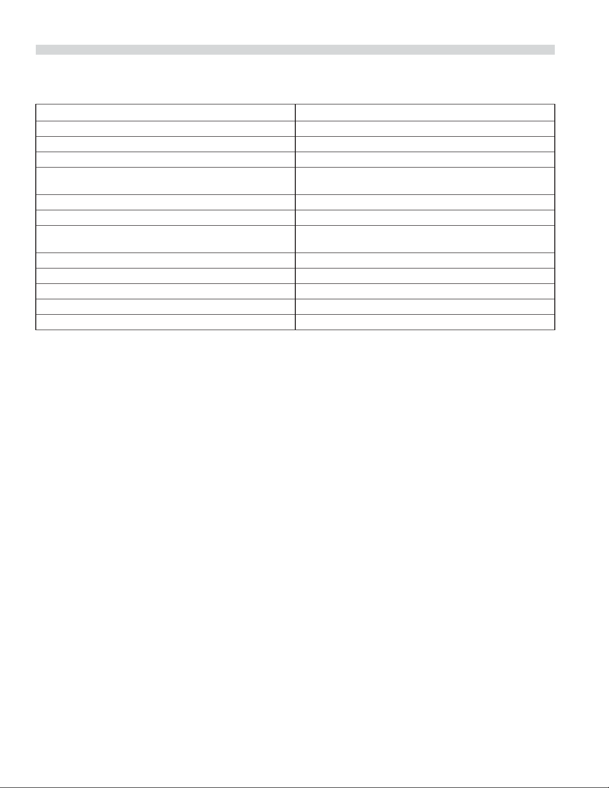
PROBLEM/SOLUTIONS
Problem Solution
Cakes are dark on the sides and not done in the center Lower oven temperature
Cakes edges are too brown Reduce number of pans or lower oven temperature
Cakes have light outer color Raise temperature
Cake settles slightly in the center Bake longer or raise oven temperature slightly.
Do not open doors too often or for long periods
Cake ripples Overloading pans or batter is too thin
Cakes are too coarse Lower oven Temperature
Pies have uneven color pans Reduce number of pies per rack
or eliminate use of bake pans
Cupcakes crack on top Lower oven temperature
Meats are browned and not done in center Lower temperature and roast longer.
Meats are well done and browned Reduce time. Limit amount of moisture
Meats develop hard crust Reduce temperature or place pan of water in oven.
Rolls have uneven color Reduce number or size of pans.
Part Number 1955203 rev 4 4/15 19
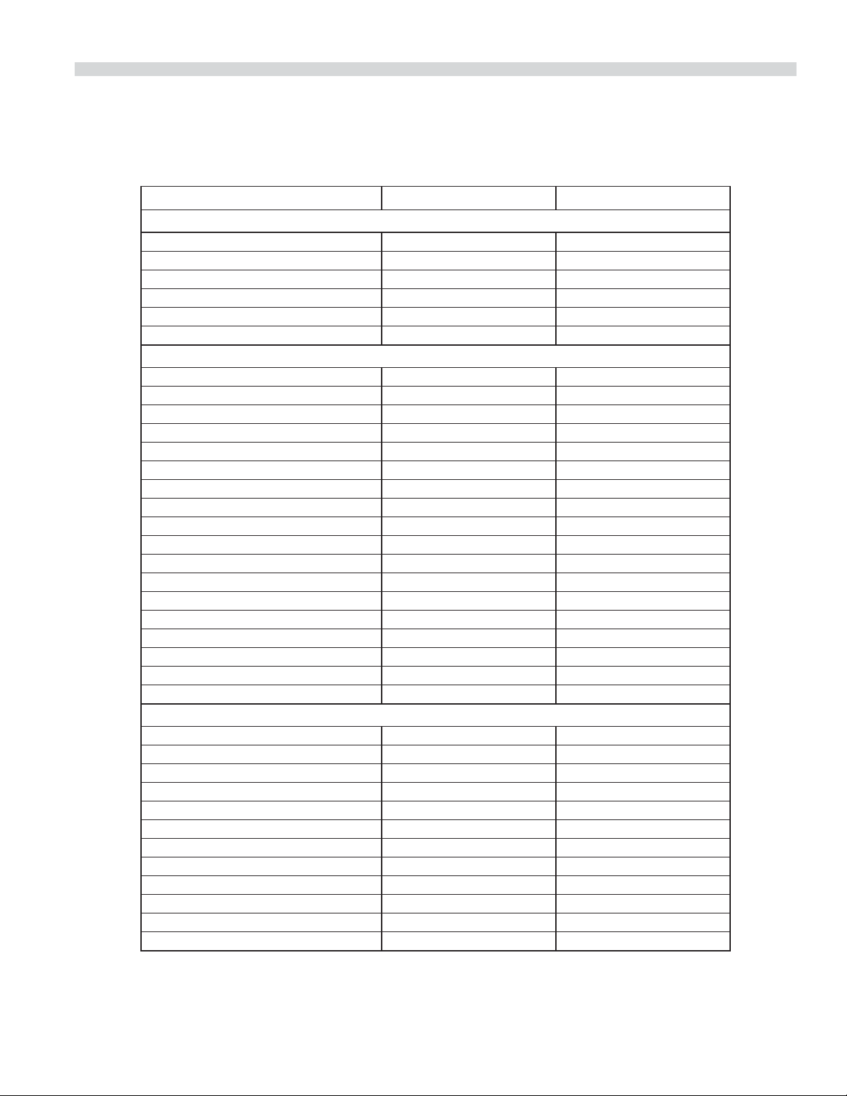
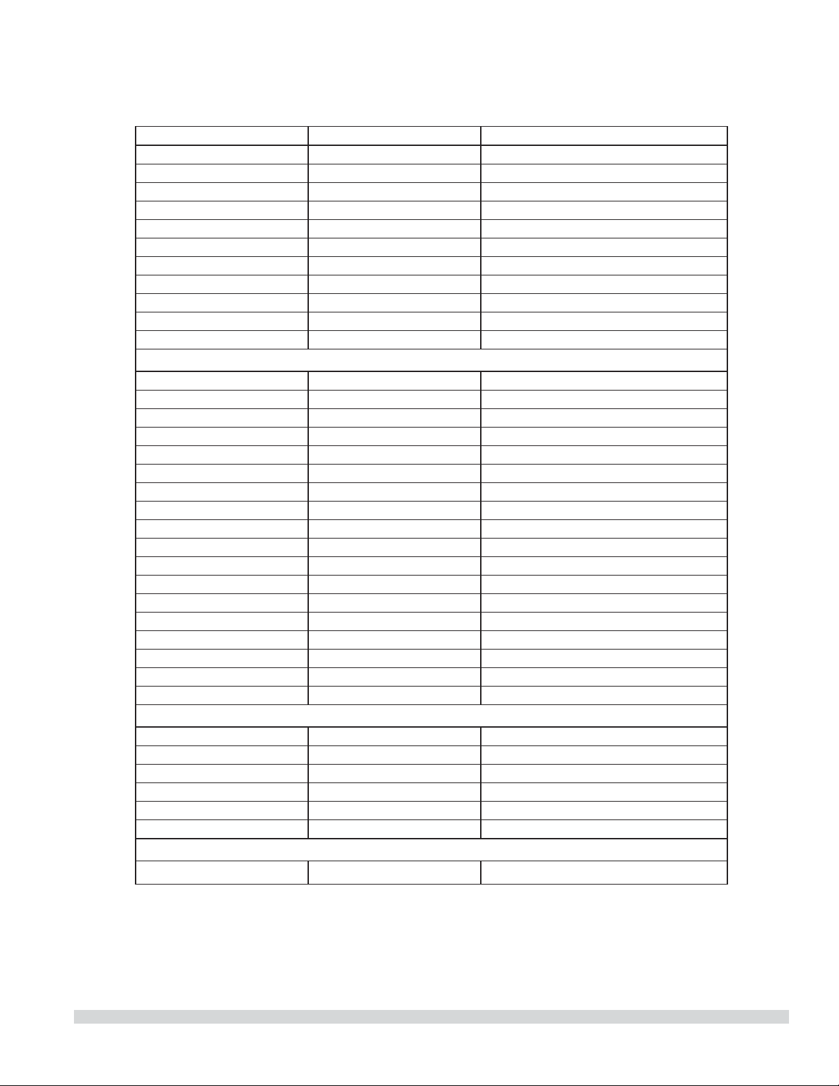
COOKING GUIDE
The following suggested times and temperatures are provided as a starting guide. Elevation, atmospheric conditions, recipe,
cooking pans and oven loading may a ect your actual results.
PRODUCT TEMPERATURE (ºF) TIME
Cakes
White Sheet Cakes – 5 lbs 300º 20 min
White Sheet Cakes – 6 lbs 300º 22 min
Yellow Sheet Cake – 5 lbs 325º 15 min
Chocolate Layer Cake – 21 oz 300º 22 min
Angel Food Cake 375º 22 min
Brownies 350º 15 min
Breads
Soda Biscuits 400º 6 min
Yeast Rolls 325º 24 min
Sweet Bread 325º 24 min
Corn Bread 350º 22 min
Gingerbread 300º 24 min
Apple Turnovers 350º 25 min
Cream Pu s 300º 25 min
Sugar Cookies 325º 12 min
Chocolate Chip cookies 375º 8 min
Apple Pie (Fresh) 375º 25 min
Blueberry Pie (Fresh) 350º 30 min
Blueberry Pie (Frozen) 300º 50 min
Pumpkin Pie (Frozen) 300º 50 min
Frozen Pizza 300º 6 min
Macaroni & Cheese 350º 15 min
Fish Sticks 350º 16 min
Stu ed Peppers 350º 45 min
Baked Potatoes 350º 60 min
Meats
Chick Parts 350º 45 min
Hamburger Patties-10/lb frozen 350º 8 min
Hamburger Patties - 10/lb fresh 350º 5 min
Hamburger Patties - 4/lb frozen 350º 12 min
Hamburger Patties – 4/lb fresh 350º 8 min
Meatloaf – 4lb 325º 45 min
Bacon 350º 10 min
Roast Beef 20lb 325º 3 hr 15 min
Prime Rib 10lb 300º 1 hr 45 min
Stu ed Port chops 350º 45 min
Lamb chops 375º 40 min
Boneless Veal Roast 300º 3 Hr
Part Number 1955203 rev 4 4/1520
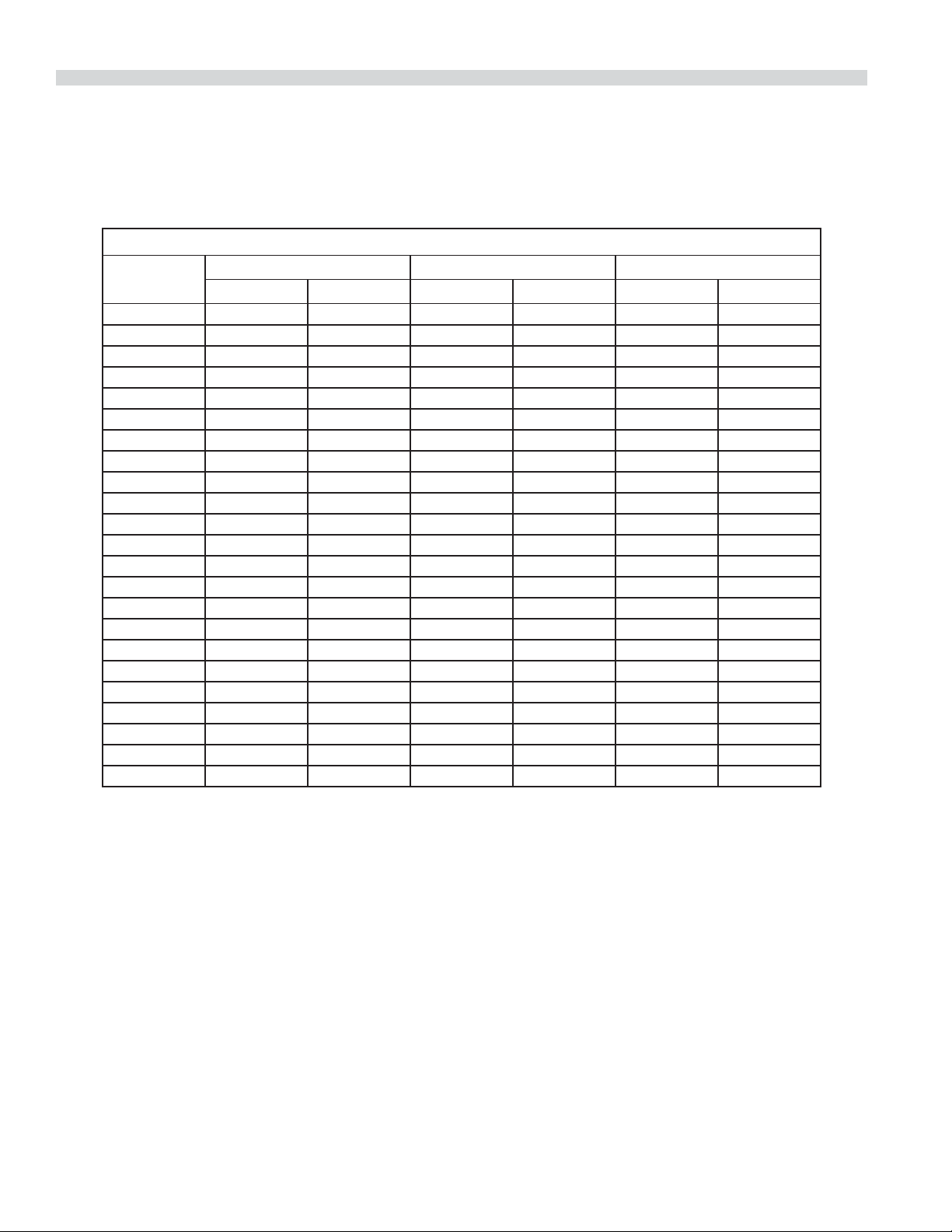
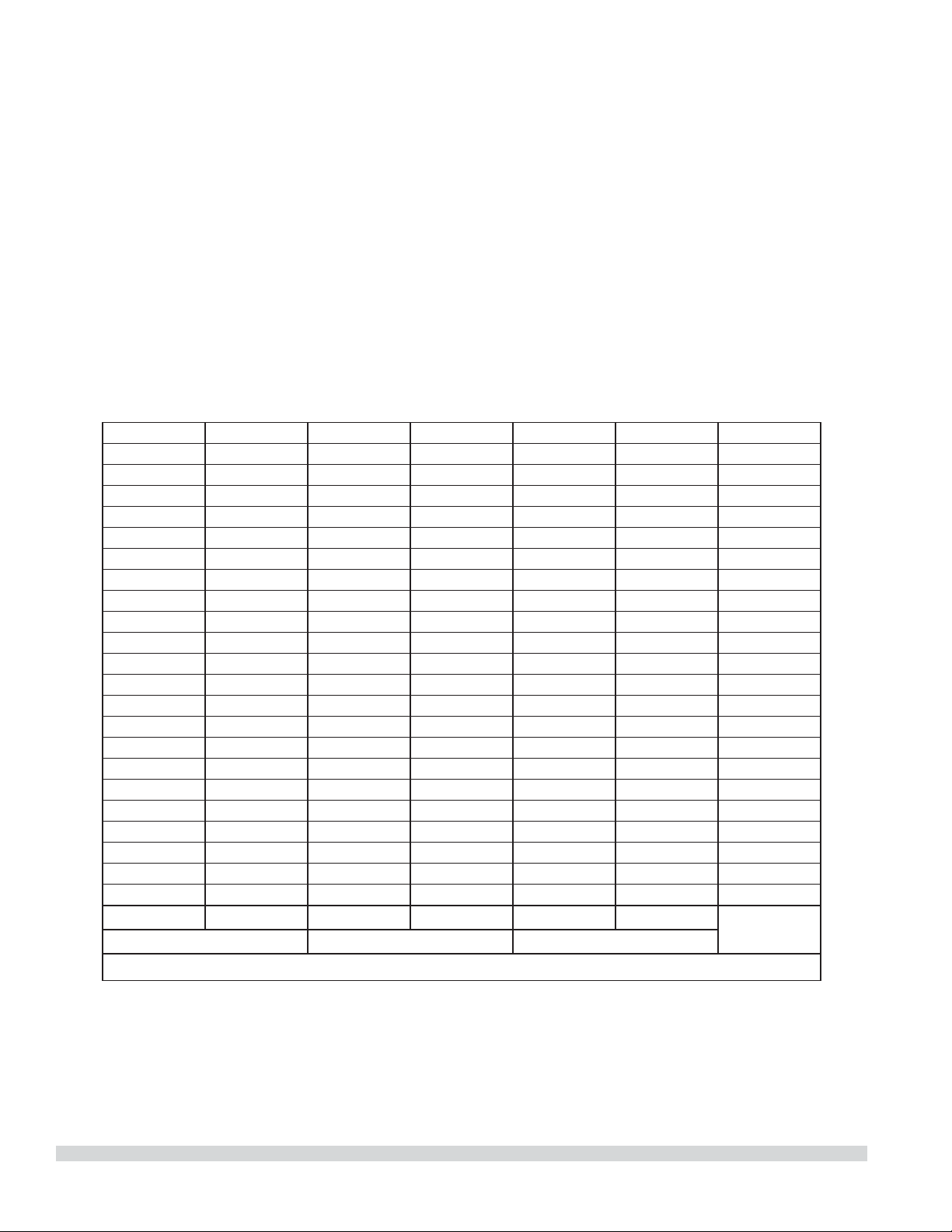
COOK AND HOLD
Please refer to the operating instructions to program the 450 and 455 control units for Cook and Hold feature. The times and
temperatures listed below are to be used as a starting guide. Your actual results may vary greatly depending on your elevation,
atmospheric conditions and other items being cooked at the same time.
Time in Hours
Weight in lbs
Temperature: 200ºF Temperature: 250ºF Temperature: 300ºF
Rare Medium Rare Medium Rare Medium
8 2.5 3.5 1.5 2 1.25 1.5
9 2.75 3.75 1.75 2.25 1.25 1.75
10 3 4.25 2 2.5 1.5 1.75
11 3.25 4.5 2 2.75 1.5 1.75
12 3.5 5 2.25 3 1.5 2
13 3.75 5 2.5 3.25 1.5 2.25
14 4 5.75 2.5 3.5 1.75 2.5
15 4.25 6 2.75 3.5 2 2.5
16 4.5 6.25 2.75 3.75 2 2.75
17 4.75 6.5 3 4 2.25 2.75
18 4.75 6.75 3.25 4.25 2.25 3
19 5 7.25 3.25 4.25 2.25 3
20 5.25 7.5 3.5 4.5 2.5 3.25
21 5.5 7.75 3.5 4.75 2.75 3.5
22 5.75 7.75 3.5 4.75 2.75 3.5
23 6 8.25 3.75 5 2.75 3.75
24 6 8.75 3.75 5 2.75 3.75
25 6.25 9 4.25 5.5 3 4
26 6.5 9.25 4.25 5.5 3.25 4.25
27 6.75 9.5 4.25 5.75 3.25 4.25
28 7 9.75 4.5 6 3.25 4.25
29 7.25 10 4.75 6.25 3.5 4.5
30 7.25 10.25 4.75 6.25 3.5 4.5

Part Number 1955203 rev 4 4/15 21
CLEANING AND MAINTENANCE
NOTE: Disconnect line cord from power supply before
cleaning or servicing.
Break-In Period
When oven is new, operate it for one hour at 375°F (191°C)
before you begin your normal cooking operation. After
cooling, wipe the interior, including the racks, with a clean
damp cloth.
Exterior Cleaning
Establish a regular schedule. Any spills should be wiped o
immediately.
1. The oven should always be allowed to cool su ciently
before any cleaning is attempted.
2. Wipe exposed, cleanable surface when cool with a mild
detergent and hot water. Stubborn residue spots may be
removed with a lightweight non-metallic scouring pad.
Dry thoroughly with a clean cloth.
3. Stubborn stains may be removed by using a non-metallic
abrasive pad, rubbing in the direction of the metal’s grain.
If necessary, for particularly heavy deposits, you may mix
a thin paste of water and scouring powder, and apply
it with a sponge. Be careful to apply light pressure and
remember to rub only in the direction of the grain in the
metal.
4. The control panel surface is easily cleaned with hot water,
soap and a soft cloth. Do not use hard abrasives, solvent
type materials or metallic scouring pads since these will
scratch or cloud the surface.
5. Never spray the perforated areas of the control panel with
steam or water jets, as this allow moisture into the control
cavity. Moisture could damage the electrical components
or place the operator at risk of electrical shock.
Interior Cleaning
Establish a regular cleaning schedule or wipe o on the same
day when spillovers occur.
1. Cool down oven.
2. Remove oven racks.
3. Lift rack guides on either side of oven o of holders. Racks
and guides may be run through dishwasher while oven
cavity is being cleaned.
4. Clean with soap and water using a non-metallic scouring
pad, if necessary. If dirt and grease have accumulated, a
mild ammonia solution or commercial oven cleaner such
as Easy-O or Dow may be used.
5. To reinstall, reverse procedure. Place the bottom of the
rack guide against the cavity wall. Keeping the top pulled
away from the wall lift up. Push the top of the guide
against the wall and push down locking it into place.
Fan Area Maintenance
If aluminum foil is routinely used to wrap food or cooking
vessels during oven operation, the following preventive
maintenance must be performed:
1. Turn power switch to “O ” position
2. Remove oven racks and rack guides.
3. Remove air ba e and clean any stains or deposits.
4. Check blower wheel and air ba e for particles of
aluminum foil or food deposits. Clean ns of blower
wheel. (CAUTION: edges of blower wheel ns may be
sharp).
5. Reinstall the air ba e, rack guides and oven racks.
This simple practice, if performed on a regular basis will keep
your Garland oven operating at peak performance.
Motor Care
The motor on your convection oven is maintenance free
since it is constructed with self-lubricating sealed ball
bearings. It is designed to provide durable service when
treated with ordinary care. We have a few suggestions
to follow on the care of your motor. When the motor is
operating, it cools itself internally by air entering at the rear
of the motor case, provided proper clearance has been
allowed.
Since the blower wheel is in the oven cavity it is at the same
temperature as the oven. If the motor is stopped while the
oven is hot, the heat from the blower wheel is conducted
down the shaft and into the armature of the motor. This
action could shorten the life of the motor.
We recommend, at the end of the bake or roasting period,
when the oven will be idle for any period of time, or before
shutting down completely, that the doors be left open
slightly. On the 400 series controllers press the COOL DOWN
key on the control panel. The fan will continue to run until
the oven cools down to 150°F (66°C).

Part Number 1955203 rev 4 4/1522
At the end of the day, press the ON/OFF key, for the 400
series controllers to activate the Auto Cool Down feature. The
fan will run on high until the oven cavity drops below 150°F
(66°C). When the oven temperature drops below 150°F (66°C)
the oven turns o . This feature protects the oven motor from
pre-mature failure. On the 200 series controllers, push the
rocker switch to COOL position. Once cool set the rocker
switch to OFF.
NOTE: Optimal cool-down will be achieved with the door
open slightly.
CLEANING AND MAINTENANCE Continued

GARLAND
1177 KAMATO ROAD, MISSISSAUGA, ONTARIO, CANADA. L4W 1X4
8884427526
WWW.GARLANDGROUP.COM
To learn how Manitowoc Foodservice and its leading brands can equip you, visit our global web site at
www.manitowocfoodservice.com, then discover the regional or local resources available to you.
©2014 Manitowoc Foodservice except where explicitly stated otherwise. All rights reserved. Continuing product improvement may necessitate change of speci cations without notice.
Part Number 1955203 rev 4 4/15
Every new piece of Manitowoc Foodservice equipment comes with KitchenCare™ and you choose the level of service that meets
your operational needs from one restaurant to multiple locations.
StarCare – Warranty & lifetime service, certi ed OEM parts, global parts inventory, performance audited
ExtraCare — CareCode, 24/7 Support, online/mobile product information
LifeCare – Install & equipment orientation, planned maintenance, KitchenConnect™, MenuConnect
Talk with KitchenCare™ • 1-844-724-CARE • www.mtwkitchencare.com
GARLAND
1177 KAMATO ROAD, MISSISSAUGA, ONTARIO, CANADA, L4W 1X4
8884427526
WWW.GARLANDGROUP.COM
To learn how Manitowoc Foodservice and its leading brands can equip you, visit our global web site at
www.manitowocfoodservice.com, then discover the regional or local resources available to you.
©2014 Manitowoc Foodservice except where explicitly stated otherwise. All rights reserved. Continuing product improvement may necessitate change of speci cations without notice.
Numéro de Pièce 1955203 rév 4 4/15
Every new piece of Manitowoc Foodservice equipment comes with KitchenCare™ and you choose the level of service that meets
your operational needs from one restaurant to multiple locations.
StarCare – Warranty & lifetime service, certi ed OEM parts, global parts inventory, performance audited
ExtraCare — CareCode, 24/7 Support, online/mobile product information
LifeCare – Install & equipment orientation, planned maintenance, KitchenConnect™, MenuConnect
Talk with KitchenCare™ • 1-844-724-CARE • www.mtwkitchencare.com

Entretien du Moteur
Le moteur de ce four à convection est sans entretien étant
donné qu’il est fabriqué avec des roulements à billes
autolubri ants étanches. Il est conçu pour o rir un service
durable avec un entretien normal. Nous o rons ci-dessous
quelques suggestions à suivre en ce qui concerne le
moteur. Lors du fonctionnement du moteur, il se refroidit
automatiquement par l’air pénétrant dans la partie arrière de
son carter, à condition qu’un dégagement su sant existe à
l’arrière de l’appareil.
Étant donné que le ventilateur se trouve dans le four, il est
à la même température que celui-ci. Si le moteur est arrêté
pendant que le four est chaud, la chaleur du ventilateur
est transmise à l’arbre et à l’induit du moteur. Ceci peut
raccourcir la durée de vie du moteur.
We recommend, at the end of the bake or roasting period,
when the oven will be idle for any period of time, or before
shutting down completely, that the doors be left open
slightly. On the 400 series controllers press the COOL DOWN
key on the control panel. The fan will continue to run until
the oven cools down to 150°F (66°C).
Nous recommandons, à la n de la période de cuisson ou
de rôtissage, quand le four est au ralenti pour n’importe
quelle période de temps ou avant de l’arrêter complètement,
de laisser les portes entrouvertes. Sur les contrôleurs série
400, appuyer sur la touche COOL DOWN du tableau de
commande. Le ventilateur continuera de fonctionner jusqu’à
ce que la température du four descende à 150°F (66°C).
À la n de la journée, appuyer sur la touche ON/OFF,
pour les contrôleurs série 400, pour activer la fonction de
refroidissement automatique. Le ventilateur tournera à
grande vitesse jusqu’à ce que la température à l’intérieur
du four soit inférieure à 150°F (66°C). Pendant ce temps, la
DÉL « AUTO COOL DOWN » restera allumée. Une fois que
la température du four est descendue au-dessous de 150°F
(66°C), le four s’éteint. Cette fonction protège le moteur du
four d’une usure prématurée. Sur les contrôleurs série 200,
pousser le commutateur à bascule en position COOL. Une
fois le four refroidi, régler le commutateur à bascule sur OFF.
NOTA : Le refroidissement optimal est obtenu avec la porte
du four entrouverte.
ENTRETIEN ET NETTOYAGE (suite)
Numéro de Pièce 1955203 rév 4 4/15 23

ENTRETIEN ET NETTOYAGE
REMARQUE: Débrancher le cordon électrique de la source
d’alimentation avant le nettoyage ou l’entretien.
Période de Rodage
Quand le four est neuf, le faire fonctionner pendant une
heure à 375°F (191°C) avant de commencer toute opération
normale de cuisson. Après refroidissement, essuyer
l’intérieur, y compris les grilles, avec un chi on propre et
humide.
Nettoyage Extérieur
Établir un calendrier de nettoyage régulier. Tout déversement
doit être essuyé immédiatement.
1. Il est indispensable de laisser su samment refroidir le
four avant toute opération de nettoyage.
2. Essuyer à froid les surfaces exposées et nettoyables avec
un chi on humecté d’une solution savonneuse non
abrasive et d’eau chaude. Les tâches rebelles peuvent être
retirées à l’aide d’un tampon à récurer non-métallique.
Bien essuyer avec un chi on propre.
3. Les taches rebelles peuvent être retirées à l’aide d’un
tampon de récurage non-métallique utilisé dans le sens
du grain du métal. Si nécessaire, en cas de salissures
importantes, mélanger en pâte ne un peu d’eau et de la
poudre de récurage et l’appliquer à l’aide d’une éponge.
Ne pas appliquer de fortes pressions et toujours travailler
dans le sens du grain du métal.
4. La surface du panneau de commande se nettoie
facilement avec de l’eau chaude, du savon et un chi on
doux. Ne pas utiliser de produits abrasifs durs, de solvants
ni de tampons à récurer métalliques qui peuvent ternir ou
rayer la surface.
5. Ne jamais diriger des jets d’eau ou de vapeur sur les
zones perforées du panneau de commande, car cela
fera pénétrer de l’humidité dans l’espace de commande.
L’humidité pourrait endommager les composants
électriques ou présenter un risque de choc électrique
pour l’opérateur.
Nettoyage Intérieur
Établir un calendrier de nettoyage régulier ou essuyer le jour
même tout déversement.
1. Refroidir le four.
2. Retirer les grilles du four.
3. Soulever de leurs supports les guides de grilles d’un côté
du four, soulever la partie supérieure de la paroi du four,
passer les clips, pousser vers le bas et retirer. Les grilles et
les guides peuvent passer dans le lave-vaisselle pendant
le nettoyage de l’intérieur du four.
4. Nettoyer à l’eau et au savon doux en utilisant un
tampon à récurer non-métallique si nécessaire. En cas
d’accumulation de saleté et de graisse, on peut utiliser
une solution peu concentrée d’ammoniac ou un produit
de nettoyage pour fours du commerce comme Easy-O
ou Dow.
5. Pour le remontage, inverser la procédure. Placer le bas du
guide de grille contre la paroi du four. En maintenant la
partie supérieure éloignée de la paroi, soulever. Pousser
le haut du guide contre la paroi et pousser vers le bas
pour le bloquer en place.
Maintenance de la Zone du Ventilateur
Si on utilise habituellement du papier aluminium pour
envelopper les aliments ou les récipients de cuisson dans
le four, il est nécessaire d’e ectuer l’entretien préventif
suivante:
1. Mettre l’interrupteur d’alimentation en position
« OFF ».
2. Retirer les crémaillères et les guides des crémaillères du
four.
3. Retirer le dé ecteur d’air et nettoyer toutes les taches ou
dépôts.
4. Véri er la présence de particules d’aliments ou
d’aluminium sur le ventilateur et le dé ecteur. Nettoyer
les ailettes du ventilateur. (Attention : les bords des
ailettes peuvent être coupants).
5. Remettre en place le dé ecteur, les guides de crémaillère
et les crémaillères dans le four.
Cette pratique simple si elle est réalisée régulièrement,
maintiendra votre four Garland dans un état de
fonctionnement impeccable.
Numéro de Pièce 1955203 rév 4 4/1522
CUISSON ET MAINTIEN AU CHAUD
Consulter les instructions d’utilisation pour la programmation des unités de commande de séries 450 et 455 pour la
caractéristique de cuisson et maintien au chaud. Les temps et les températures ci-dessous sont a utiliser comme guide de
départ. Les résultats e ectifs peuvent varier de façon importante selon l’altitude, les conditions atmosphériques et lest autres
aliments cuits en même temps.
TEMPS EN HEURES
Poids en lb
Température: 200°F Température: 250°F Température: 300°F
Saignant À point Saignant À point Saignant À point
8 2.5 3.5 1.5 2 1.25 1.5
9 2.75 3.75 1.75 2.25 1.25 1.75
10 3 4.25 2 2.5 1.5 1.75
11 3.25 4.5 2 2.75 1.5 1.75
12 3.5 5 2.25 3 1.5 2
13 3.75 5 2.5 3.25 1.5 2.25
14 4 5.75 2.5 3.5 1.75 2.5
15 4.25 6 2.75 3.5 2 2.5
16 4.5 6.25 2.75 3.75 2 2.75
17 4.75 6.5 3 4 2.25 2.75
18 4.75 6.75 3.25 4.25 2.25 3
19 5 7.25 3.25 4.25 2.25 3
20 5.25 7.5 3.5 4.5 2.5 3.25
21 5.5 7.75 3.5 4.75 2.75 3.5
22 5.75 7.75 3.5 4.75 2.75 3.5
23 6 8.25 3.75 5 2.75 3.75
24 6 8.75 3.75 5 2.75 3.75
25 6.25 9 4.25 5.5 3 4
26 6.5 9.25 4.25 5.5 3.25 4.25
27 6.75 9.5 4.25 5.75 3.25 4.25
28 7 9.75 4.5 6 3.25 4.25
29 7.25 10 4.75 6.25 3.5 4.5
30 7.25 10.25 4.75 6.25 3.5 4.5
Numéro de Pièce 1955203 rév 4 4/15 21
GUIDE DE CAISSON
Les temps et les températures suggérés suivants sont fournis comme guide de départ. L’altitude, les conditions
atmosphériques, l’alimentation en gaz, la recette, les plats de cuisson et le chargement du four peuvent a ecter les résulats
dé nitifs obtenus.
PRODUIT TEMPÉRATURE (°F) TEMPS
Gâteaux
Gâteaux Blancs Étagés – 5 lb 300° 20 min
Gâteaux Blancs Étagés – 6 lb 300° 22 min
Gâteau Jaune Étagé – 5 lb 325° 15 min
Gâteau Étagé au Chocolat – 21 oz 300° 22 min
Gâteau des Anges 375° 22 min
Carrés au Chocolat 350° 15 min
Pains
Biscuits à la Poudre Levante 400° 6 min
Petits Pains à la Levure 325° 24 min
Pain Viennois 325° 24 min
Pain de Maïs 350° 22 min
Pain d’Épice 300° 24 min
Chaussons aux Pommes 350° 25 min
Choux à la à la Crème 300° 25 min
Biscuits au Sucre 325° 12 min
Biscuits aux Copeaux De Chocolat 375° 8 min
Tarte aux Pommes (Fraîche) 375° 25 min
Tarte aux Bleuets (Fraîche) 350° 30 min
Tarte aux Bleuets (Congelée) 300° 50 min
Tarte à la Citrouille (Congelée) 300° 50 min
Pizza Congelée 300° 6 min
Macaronis au Fromage 350° 15 min
Bâtonnets de Poisson 350° 16 min
Poivrons Farcis 350° 45 min
Pommes de Terre Au Four 350° 60 min
Viandes
Morceaux de Poulet 350° 45 min
Galettes de Bœuf - 10/lb (Congelées) 350° 8 min
Galettes de Bœuf - 10/lb (Fraîches) 350° 5 min
Galettes de Bœuf - 4/lb (Congelées) 350° 12 min
Galettes de Bœuf - 4/lb (Fraîches) 350° 8 min
Pain de Viande - 4 lb 325° 45 min
Bacon 350° 10 min
Rôti de Bœuf – 20 lb 325° 3 hr 15 min
Côte de Bœuf – 10 lb 300° 1 hr 45 min
Côtelettes de Porc Farcies 350° 45 min
Côtelettes d’Agneau 375° 40 min
Rôti de Veau Sans Os 300° 3 Hr
Numéro de Pièce 1955203 rév 4 4/1520
PROBLÈMES/SOLUTIONS
Problèmes Solutions
Si le gâteau est doré sur les côtés
et n’est pas cuit au centre
Abaisser la température du four
Si les bords du gâteau sont brûlés Réduire le nombre de plats ou la température du four
Si la couleur du gâteau est pâle Augmenter la température
Si le gâteau s’a aisse légèrement au centre Prolonger le temps de cuisson ou augmenter légèrement la
température du four. Ne pas ouvrir les portes trop souvent ni
pendant de longues périodes de temps
Si le gâteau comporte des rides Surcharge des plats ou pâte trop ne
Si le gâteau est trop dur Abaisser la température du four
Si les tartes sont de couleur inégale Réduire le nombre de tartes par grille ou éliminer les moules
de cuisson
Si les petits gâteaux se fendent sur le dessus Abaisser la température du four
Si les viandes sont dorées mais pas cuites au centre Abaisser la température du four
et prolonger le temps de cuisson.
Si les viandes sont bien cuites et roussies Réduire le temps de cuisson.
Limiter la quantité d’humidité
Si les viandes ont une croûte dure Réduire la température ou placer un plat avec
de l’eau dans le four
Si les pains mollets sont de couleur inégale Réduire le nombre ou la taille des moules
Numéro de Pièce 1955203 rév 4 4/15 19

14. Pour le réchau age des plats en cocotte congelés,
préchau er le four à 100° de plus que la température
suggérée. Revenir ensuite à la température de cuisson
suggérée après le chargement du four. Cela permet de
compenser la chute de température provoquée par
l’introduction d’une grande quantité d’aliments froids
dans le four.
15. Utiliser des rehausses de moules ou des moules de 18
x26 po d’une profondeur de deux pouces pour la cuisson
des aliments enrobés de pâte dont le poids dépasse huit
livres, par exemple le gâteau renversé aux ananas.
16. Ne jamais placer quoi que se soit directement sur le fond
du four. Cela empêche la circulation de l’air et cause une
cuisson inégale.
17. N’actionnez jamais le four si des couvertures extérieures
l’unes des sont enlevées. Ces couvertures sont
nécessaires pour la protection contre l’exposition pour
vivre les pièces électriques et devraient seulement être
enlevées quand le four est entretenu par un personnel de
service quali é.
18. Ceci est un four de cuisson commercial non destiné à
des installations de cuisson non commerciales ou à des
produits non alimentaires.
19. Utiliser des plats et plateaux alimentaires pour fours.
20. Utiliser des gants isolants pour ajouter ou retirer des
plats/plateaux du four quand celui-ci est allumé.
21. Faire attention pour retirer les produits du four a n
d’éviter les déversements pouvant causer des blessures
graves sur la peau nue et aux yeux. Les niveaux élevés de
la crémaillère des fours sont à hauteur des yeux.
22. L’extérieur des fours chau e pendant le fonctionnement;
faire attention à ne pas se brûler.
23. Une manipulation correcte du poids et une bonne
répartition des produits dans les plats ou les plateaux
empêcheront les produits de glisser et éviteront les
déversements et les blessures.
24. Ne pas faire fonctionner le ventilateur du four avec la
grille de protection retirée.
25. Le niveau de pression acoustique du four en
fonctionnement ne devrait pas dépasser 70 dB(A).
REMARQUE: Une certaine quantité d’humidité s’échappera
autour des portes du four lors de la cuisson d’aliments à forte
teneur en humidité comme le poulet, les pommes de terre
etc. Cela est normal.
RECOMMANDATIONS D’UTILISATION ET
PRÉCAUTIONS GÉNÉRALES DE SÉCURITÉ
1. Bien préchau er le four (environ 20 minutes) avant son
utilisation.
2. D’une façon générale, réduire la température de 25° à
50° par rapport à celle d’un four conventionnel/standard.
Le temps de cuisson peut également être plus court
et pour cette raison nous recommandons de surveiller
attentivement la première cuisson de chaque type de
produits.
3. Utiliser le tableau des temps et des températures de
cuisson suggérés comme guide. Ces valeurs peuvent
varier en fonction de la quantité d’aliments placés dans
le four, de la température et du mélange de produits, (en
particulier de l’humidité) et de la densité des produits.
4. Noter les temps de cuisson, les températures et les
quantités d’aliment pour les di érents produits. Une
fois ces renseignements notés, les autres opérations de
cuisson seront similaires.
5. Si possible, commencer par cuire les produits ayant
la température de cuisson la plus basse et passer
progressivement aux températures plus élevées.
6. Si le réglage de température précédent est plus élevé
de 10° à la température nécessaire pour les charges
suivantes, utiliser le mode de refroidissement pour
atteindre la température souhaitée avant de régler à
nouveau le thermostat.
7. Pour charger le four, travailler aussi vite que possible pour
éviter les pertes de chaleur.
8. Le four continue à chau er même après l’arrêt de la
minuterie. Les aliments doivent être retirés du four aussi
vite que possible pour éviter de trop les faire cuire.
9. Centrer les plats dans le four et les répartir également sur
les grilles pour permettre une bonne circulation de l’air à
l’intérieur du four.
10. Pour la pâtisserie, peser ou mesurer les produits dans
chaque moule pour assurer une cuisson régulière.
11. Pour la cuisson de 6 plats, utiliser les positions de grilles 2,
4, 6, 8, 10 et 12, en commençant par le haut.
12. Ne pas surcharger le four. Dans la plupart des cas, on
recommande d’utiliser 6 plats (gâteaux, biscuits, pains
mollets, etc.). Cependant, il est possible d’utiliser un
maximum de 13 plats pour la cuisson des bâtonnets
de poisson, des pépites de poulet et des hamburgers. Il
faudra probablement ajuster les temps de cuisson.
13. Les moules à mu ns doivent être placés dans le four
avec l’arrière vers la porte ou avec le côté court du moule
face à l’avant. Cela permet d’obtenir une cuisson plus
uniforme.
Numéro de Pièce 1955203 rév 4 4/1518

3. Appuyez sur la touche START/CANCEL pour commencer
le processus de cuisson/minuterie.
4. Lorsque le processus de cuisson/minuterie est terminé
pour chaque niveau, un signal sonore de n de cuisson se
fait entendre et l’a chage indique quel est le niveau où
la cuisson est terminée.
P. ex. : SH-1.
5. Pour arrêter l’alarme, appuyez sur la touche produit donc
la DEL clignote.
Exemple: Deux pro ls produit contiennent la même
température de cuisson, la même vitesse du ventilateur et
sont tous les deux programmés sur temps exible - touches
1 et 6.
Deux plateaux contenant des aliments vont cuire dans le
four en même temps. Le premier plateau utilisera la touche
produit 1 et sera placé dans la position de grille 2. Le second
plateau utilisera la touche produit 6 et sera placé dans la
position de grille 4. Une fois que le four a che le mot LOAD:
1. Chargez les aliments dans le four sur le niveau 2.
2. Appuyez sur la touche produit 1, ensuite sur la touche
niveau 2.
INSTRUCTIONS D’UTILISATION (suite)
3. Appuyez sur la touche START/CANCEL pour démarrer la
cuisson du niveau 2.
4. Chargez les aliments dans le four sur le niveau 4.
5. Appuyez sur la touche produit 6, ensuite que la touche de
niveau 4.
6. Appuyez sur la touche START/CANCEL pour démarrer la
cuisson sur le niveau.
7. Lorsque les aliments du niveau 2 sont cuits, une alarme se
fait entendre et l’a chage indique en clignotant DONE,
ensuite SH-2, alors que la DEL de la touche produit 1
clignote.
8. Pour arrêter l’alarme, appuyez sur la touche
produit 1.
9. Lorsque les aliments du niveau 4 sont cuits, une alarme se
fait entendre et l’a chage indique en clignotant DONE,
ensuite SH-4, alors que la DEL de la touche produit 6
clignote.
10. Pour arrêter l’alarme, appuyez sur la touche produit 6.
Numéro de Pièce 1955203 rév 4 4/15 17

REMARQUE: Le contrôleur acceptera uniquement les
températures de cuisson pour les pro ls pour lesquels un
temps de cuisson a été réglé. Si l’on appuie sur la touche
produit après le dernier pro l programmé, l’appareil a chera
la première température.
• Appuyez sur la touche SET après la saisie des
dernières températures de cuisson, le mot HOLD
s’A che.
7. Utilisez la touche START/CANCEL pour sélectionner yes
ou no. Appuyez sur la touche SET.
8. Si yes a été sélectionné, la DEL HOLD s’allume. Entrez
la température de maintien au chaud avec le cadran
(préréglé en usine sur 200°F). Appuyez sur la touche SET.
Le mot FAN s’a che et la DEL FAN s’allume.
• Réglez la vitesse du ventilateur désirée pour
le premier pro l de cuisson avec les touches
individuelles du ventilateur (HIGH, LOW ou PULSE),
appuyez sur la touche produit et réglez la vitesse
du ventilateur pour le deuxième pro l de cuisson.
Continuez jusqu’à ce que tous les pro ls possèdent
leur vitesse du ventilateur. Appuyez sur la touche
SET lorsque cette opération est terminée. Comme
c’était le cas avec la température, si l’on appuie sur la
touche produit après le dernier pro l programmé, la
première vitesse de ventilateur sera a chée.
9. L’indication FL or St sera a chée (pour temps exible
ou temps xe) (préréglée en usine sur temps exible).
Sélectionnez le temps exible ou xe à l’aide de la touche
START/CANCEL pour le premier pro l. Appuyez sur la
touche produit et sélectionnez le temps xe ou le temps
exible pour le deuxième pro l. Continuez pour tous les
pro ls. Appuyez sur la touche SET lorsque l’opération
est terminée. Si l’on appuie sur la touche produit après le
dernier pro l programmé, l’appareil a chera le premier
pro l.
10. La programmation de cette touche produit est terminée.
Cuisson avec Utilisation des Touches Produit
(Master )
1. Lors du démarrage initial, appuyez sur la touche produit
pour l’article du menu à cuire. Attendez que le mot LOAD
s’a che.
2. Chargez le four.
3. Appuyez sur la touche produit pour l’article du menu
chargé.
4. Appuyez sur la touche START/CANCEL.
5. Pour annuler l’alarme ou l’opération de maintien au
chaud, appuyez sur la touche START/CANCEL et ensuite
sur la touche produit.
Véri cation du Temps de Maintien au Chaud
(Master )
Pendant que le produit est en mode de maintien au chaud,
maintenez enfoncée la touche produit. Le temps de maintien
au chaud s’a che.
Sélection De L’a chage En Degrés Fahrenheit Ou
Celsius (Master )
Appuyez sur les touches PROG et ACTUAL TEMP en même
temps. La lettre F ou C s’a che. (préréglé en usine sur F).
Appuyez sur la touche START/CANCEL pour passer de F à C
et de C à F.
Lorsque l’unité de mesure désirée est a chée, appuyez sur
les touches PROG et ACTUAL TEMP en même temps.
Cuisson avec la Minuterie de Niveau
(Master )
L’option de minuterie de niveau est utilisée pour minuter
indépendamment chacun des 6 niveaux ou grilles di érents
à l’intérieur du four.
REMARQUE: Pour utiliser l’option de minuterie de niveau,
au moins une touche produit doit être programmée
avec un pro l de cuisson (température, temps, vitesse du
ventilateur, temps exible ou xe). La touche de programme
doit être limitée à un seul pro l de cuisson à utiliser avec
l’option de minuterie de niveau. S’il faut utiliser plus d’une
touche produit, toutes les touches produit à utiliser doivent
présenter la même température de cuisson et la même
vitesse du ventilateur. Le temps exible ou xe et le temps
de cuisson peuvent être di érents. L’option Cook-N-Hold ne
peut pas être utilisée avec l’option de minuterie de niveau.
Le fait d’appuyer sur la touche produit désirée amènera le
four à la température de cuisson souhaitée,. Une fois que le
four a atteint la bonne température de cuisson, ce qui est
indiqué par le mot LOAD sur l’a chage.
1. Appuyez sur la touche produit contenant le pro l de
cuisson désiré (1 - 9).
2. Appuyez sur la touche de niveau pour indiquer
l’emplacement du niveau à minuter (1 - 6). REMARQUE:
les touches produit et les touches niveau sont les mêmes.
INSTRUCTIONS D’UTILISATION (suite)
Numéro de Pièce 1955203 rév 4 4/1516

Cuisson Manuelle à l’aide
de la Fonction Cook-N-Hold
(Cuisson et Maintien au Chaud)
1. Appuyez sur la touche COOK/HOLD, la DEL de cette
touche s’allume.
2. Appuyez sur la touche SET - la DEL TEMP s’allume.
3. Réglez la température de cuisson à l’aide du cadran
(préréglé en usine sur 350°F).
4. Appuyez sur la touche SET - la DEL HOLD s’allume.
5. Réglez la température du maintien au chaud à l’aide du
cadran (préréglé en usine sur 200°F).
6. Appuyez sur la touche SET - la DEL FAN s’allume
7. Sélectionnez le mode de fonctionnement du ventilateur
à l’aide d’une des trois touches (3) du ventilateur (
HIGH, LOW, PULSE ) - la DEL du ventilateur sélectionné
s’allume.
8. Appuyez sur la touche SET - la DEL TIME s’allume.
9. Réglez le temps de cuisson à l’aide du cadran (préréglé en
usine sur 30:00).
10. Appuyez sur la touche SET - prêt à cuire
11. Appuyez sur la touche START/CANCEL pour démarrer la
cuisson manuelle.
Programmation des Touches Produit
(Master )
REMARQUE: Le temps de cuisson est l’élément du
programme qui dit au contrôleur que d’autres informations
(température, vitesse du ventilateur, etc.) vont être entrées
dans le contrôleur. La première étape consiste à entrer toutes
les périodes de temps nécessaires, suivies par les autres
éléments de cuisson.
1. Appuyez sur la touche PROG et maintenez-la enfoncée
pendant trois (3) secondes - tous les DEL des touches
produits s’allument.
2. Le mot CODE s’a che. Le contrôleur demande le code
d’accès. Appuyez sur les touches 4-2-7-5 et la touche
START/CANCEL. Le mot PROD s’a che pour indiquer
qu’il est possible d’accéder à la programmation des
produits.
3. Appuyez sur la touche de produit (1 - 9) où vous
souhaitez sauvegarder un programme de cuisson. Le mot
SHLF s’a che. Le contrôle demande si vous souhaitez
programmer la touche en tant que minuteur de niveau
ou en tant que pro l de cuisson. Sélectionnez votre
réponse en appuyant sur la touche START/CANCEL.
Lorsque la réponse correcte est a chée, appuyez sur la
touche SET. La DEL TIME s’allume et 30:00 s’a che.
4. Réglez le premier temps de cuisson avec le cadran. S’il est
nécessaire d’entrer plusieurs pro ls de cuisson :
• Appuyez sur la touche produit où le programme doit
être sauvegardé (1 - 9) - L’indication PR-2 s’a che.
• Réglez le second temps de cuisson avec le cadran (les
préréglages en usine pour PR-2 à PR-5 sont :00).
• Appuyez de nouveau sur la même touche produit (1
- 9) - l’indication PR-3 s’a che.
• Recommencez de la même façon pour tous les
pro ls. Lorsque le dernier temps de pro l est entré,
appuyez sur la touche SET OU :
Si vous désirez moins de cinq (5) pro ls - appuyez sur la
touche SET après le dernier pro l requis. L’indication PRE
s’a che, suivie du chi re :00. Le contrôleur demande si vous
souhaitez obtenir l’alarme de rappel (préalarme) sonore
pendant le processus de cuisson (préréglé en usine sur :00).
5. Si vous désirez le signal de préalarme, programmez à
l’aide du cadran le temps au bout duquel l’alarme doit
sonner. (P. ex. Si le produit doit être retourné à la moitié
du cycle de cuisson de 60 minutes, réglez la préalarme sur
30 minutes). Si vous ne désirez pas de préalarme, assurez-
vous que « :00 » est a ché. Appuyez sur la touche SET - la
DEL TEMP s’allume et l’a chage indique la température
de cuisson du premier pro l (préréglé en usine sur 350°F).
6. Réglez la première température de cuisson à l’aide du
cadran.
• Appuyez sur la touche produit - l’indication
PR-2 s’a che suivie de la deuxième température.
• Réglez le deuxième temps de cuisson à l’aide du
cadran.
• Répétez de la même manière que pour le temps de
cuisson, pour tous les pro ls désirés.
INSTRUCTIONS D’UTILISATION (suite)
Numéro de Pièce 1955203 rév 4 4/15 15
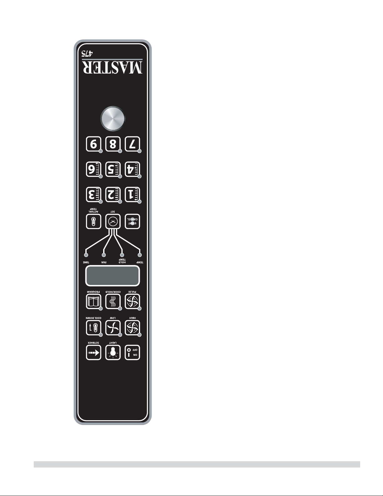
Lorsque la température intérieure de l’aliment est atteinte,
le signal sonore retentit et le message « DONE » clignote
sur l’a chage pendant 3 secondes. L’a chage passe
automatiquement à « HOLD » . Pour terminer ce cycle, la
sonde thermique doit être retirée du connecteur.
Réglage de la fonction Setback
(retour au point de consigne)
Pour con gurer ou modi er les réglages de retour au point
de consigne, maintenir enfoncée la touche SETBACK pendant
deux secondes. La DÉL TEMP s’allume et une température
s’a che. Régler la température avec le cadran, puis appuyer
sur la touche SET. La DÉL TEMP s’éteint et la DÉL TIME
s’allume (le « Temps » est réglé à 0 en usine). Régler le temps
avec le cadran, puis appuyer sur la touche SET. Appuyer
encore une fois sur la touche SET pour sortir du mode de
programmation.
REMARQUE: Pour désactiver la fonction de réduction de
puissance,r régler la température sur 250º F (121ºC) et le
minuterie sur zéro.
Commande Électronique Programmable
de la Série Master 475
Cuisson Manuelle
1. Appuyez sur la touche SET - la DEL TEMP s’allume.
2. Réglez la température à l’aide du cadran (préréglé en
usine sur 350°F).
3. Appuyez sur la touche SET - la DEL FAN s’allume.
4. Sélectionnez le mode de fonctionnement du ventilateur
en utilisant une des trois touches du ventilateur (HIGH,
LOW, PULSE) - la DEL du mode sélectionné du ventilateur
s’allume.
5. Appuyez sur la touche SET - la DEL TIME s’allume.
6. Réglez le temps de cuisson à l’aide du cadran (préréglé en
usine sur 30:00).
7. Appuyez sur la touche SET - prêt à cuire.
8. Appuyez sur la touche START/CANCEL pour démarrer la
cuisson manuelle.
INSTRUCTIONS D’UTILISATION (suite)
Numéro de Pièce 1955203 rév 4 4/1514

Si on appuie sur la touche ON/OFF pour arrêter le four et
si la température du four est supérieure à 200°F (93°C),
le four entre en mode Auto Cool Down (refroidissement
automatique). En mode de refroidissement automatique,
le ventilateur fonctionne à haute vitesse jusqu’à ce que la
température intérieure du four descende au-dessous de
150°F (66°C). Pendant ce temps, l’a chage indique
« AUTO ». Lorsque la température du four est inférieure 150°F
(66°C), le four s’arrête. Cette fonction protège le moteur du four
contre une panne prématurée. On obtient un refroidissement
optimal du four avec la porte entrouverte.
Fahrenheit/Celsius
Le défaut d’usine est Fahrenheit (F). Pour changer en (C)
Celsius, pression et prise dans « touche fantôme » située à
la droite de la touche de « Cook/Hold ». « F » apparaît dans
l’a chage. Continuez à tenir jusqu’à ce que « C » soit montré
et puis à libérer « la touche fantôme ».
Utilisation des Commandes
Le réglage de la température et du temps de cuisson se fait
de la même manière. Quand on appuie sur la touche SET,
la DEL TEMP s’allume. L’utilisateur règle la température
en tournant le cadran du contrôleur jusqu’à ce que la
température désirée soit indiquée sur l’a chage. Si on
appuie une deuxième fois sur la touche SET, la DEL TIME
s’allume ce qui permet à l’utilisateur de choisir le temps de
cuisson comme indiqué sur l’a chage. En appuyant une
troisième fois sur la touche SET, on arrête la programmation.
En appuyant sur la touche START/CANCEL, on lance le cycle
de la minuterie. Une fois le cycle terminé, en appuyant sur ce
touche on annule également le message
« DONE ». Pour annuler un cycle de la minuterie pendant
le cycle, maintenir enfoncée pendant 3 secondes la touche
START/CANCEL.
Fonctionnement en Mode Cuisson-attente
Quand on appuie sur la touche COOK/HOLD (Contrôleurs
450 et 455 uniquement) on active le mode Cook-N-Hold
(cuisson et attente) et sa DEL s’allume. Pour véri er que l’on a
choisi la bonne température d’attente, appuyer deux fois sur
la touche SET. L’a chage indique la température d’attente.
À la n du cycle de cuisson, le message « DONE » clignote sur
l’a chage et le signal sonore retentit pendant 3 secondes,
après quoi l’a chage indique « HOLD » et le four passe à la
température d’attente programmée.
Le réglage de la température de cuisson, de la température
d’attente et du temps de cuisson se fait de la même façon.
Quand on appuie sur la touche SET, la DEL TEMP s’allume.
L’utilisateur règle alors la température en tournant le
cadran du contrôleur jusqu’à ce que la température désirée
apparaisse sur l’a chage. Quand on appuie une deuxième
fois sur la touche SET, la DEL HOLD s’allume et l’utilisateur
peut régler la température d’attente souhaitée indiquée sur
l’a chage. Quand on appuie une troisième fois sur la touche
SET, la DEL TIME s’allume et l’utilisateur peut sélectionner
le temps de cuisson désiré indiqué sur l’a chage. Quand
on appuie un quatrième fois sur la touche SET, on arrête la
programmation.
Quand on appuie sur la touche START/CANCEL, on lance le
cycle de la minuterie. Une fois le cycle terminé, on appuie
sur cette touche pour e acer également le message « DONE
». Pour annuler un cycle de la minuterie pendant le cycle,
maintenir enfoncée la touche
START/CANCEL pendant 3 secondes.
Fonctionnement avec la Sonde Thermique
L’option Core Probe (sonde thermique) (Contrôleur 455
uniquement) est activée uniquement lorsque la sonde
thermique est branchée sur son connecteur. Pour régler la
température de l’intérieur de l’aliment, brancher d’abord la
sonde thermique dans son connecteur. L’a chage indique «
100 » et la DEL CORE TEMP s’allume. L’utilisateur règle alors
la température en tournant le cadran du contrôleur jusqu’à
ce que la température souhaitée apparaisse sur l’a chage.
Quand on appuie sur la touche SET, la température à
l’intérieur de l’aliment est enregistrée et le processus de
cuisson commence.
Pour régler la température du four, appuyer à nouveau sur
la touche SET. La DEL TEMP s’allume et on peut régler la
température du four en tournant le cadran du contrôleur
jusqu’à ce que la température désirée s’a che. Quand on
appuie à nouveau sur la touche SET, la DEL HOLD s’allume et
l’utilisateur peut régler la température d’attente de la même
manière.
REMARQUE: Si la température d’attente n’est pas réglée,
l’appareil utilisera la température d’attente par défaut de
150°F (66°C) ou la dernière température programmée. (La
gamme des températures d’attente va de 140°F (60°C) à
210°F (99°C).
INSTRUCTIONS D’UTILISATION (suite)
Numéro de Pièce 1955203 rév 4 4/15 13
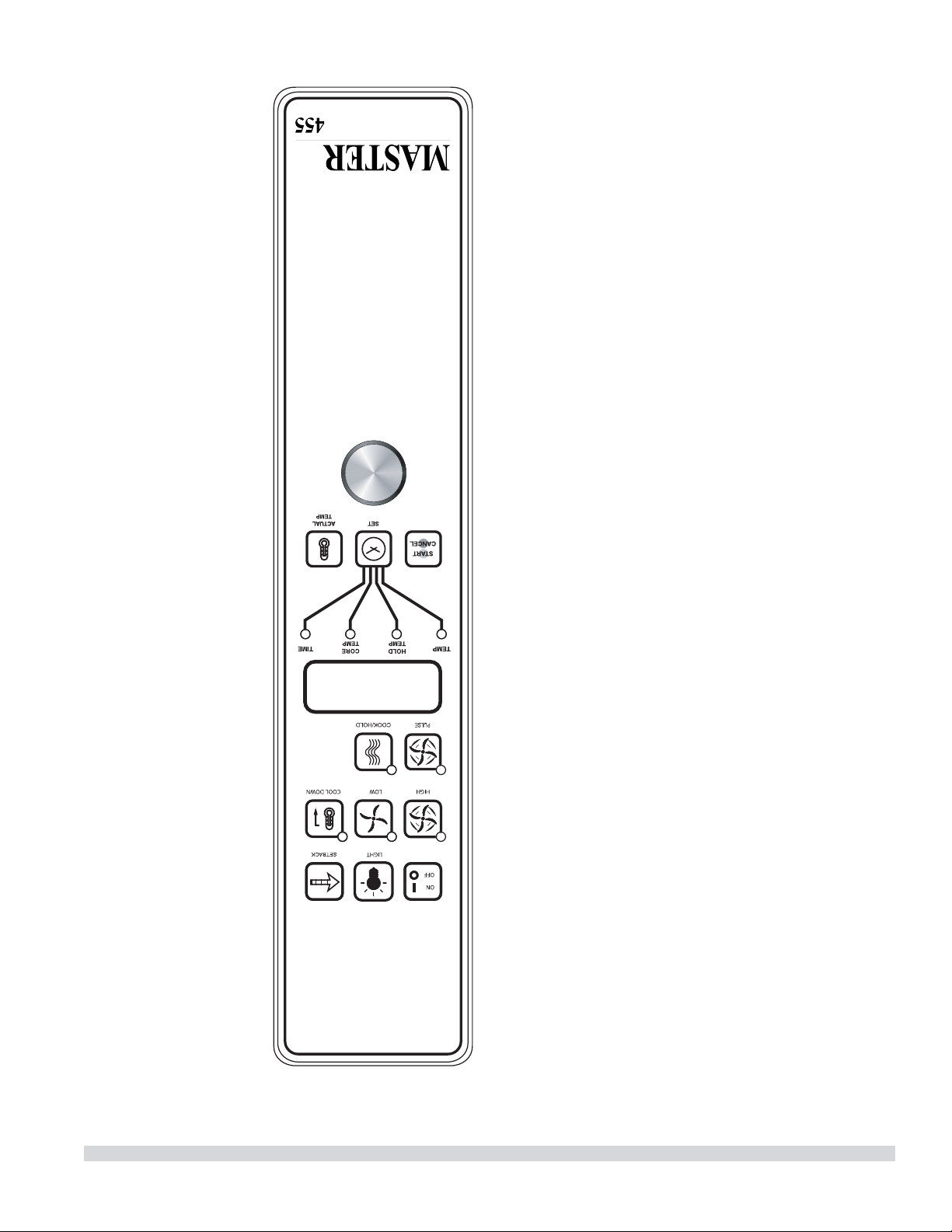
INSTRUCTIONS D’UTILISATION (suite)
Si la porte est ouverte pendant le mode de cuisson, le
ventilateur et le chau age s’arrêtent et l’a chage indique
« DOOR » jusqu’à ce que la porte soit fermée. Ceci est une
fonction de sécurité .
Quand on appuie sur la touche ACTUAL TEMP, la
température réelle du four est indiquée sur l’a chage par
incréments de 5 degrés.
Touches du Contrôleur
On appuie sur la touche ON/OFF, pour mettre en marche le
four.
Quand on appuie sur la touche LIGHT, l’éclairage s’allume
pendant 30 secondes. Les lampes fonctionnent si le
contrôleur est en mode d’arrêt (O ). Lorsque la porte du four
est ouverte, la lumière s’allume et reste allumée pendant 30
secondes.
Quand on appuie sur la touche FAN HIGH, le ventilateur
fonctionne à haute vitesse et sa DEL s’allume.
Quand on appuie sur la touche FAN LOW, le ventilateur
fonctionne à basse vitesse et sa DEL s’allume.
Quand on appuie sur la touche FAN PULSE, le ventilateur
fonctionne à basse vitesse et sa DEL s’allume. Le ventilateur
fonctionne pendant 30 secondes à basse vitesse, s’arrête
pendant 30 secondes, puis recommence le cycle.
En appuyant sur la touche SETBACK, on refroidit le four
jusqu’à une température préprogrammée, voir : Réglage de
la fonction « Set-back » (retour au point de consigne). Le four
revient automatiquement en mode de retour au point de
consigne après le temps de non utilisation préprogrammé.
L’ a chage indique « SETB ». Il s’agit d’une fonction destinée à
économiser l’énergie.
Quand on appuie sur la touche COOL DOWN, le chau age
est désactivé, le ventilateur fonctionne à haute vitesse et
sa DEL est allumée. L’a chage indique « OPEN DOOR » si la
porte est fermée, demandant à l’utilisateur d’entrouvrir la
porte. Avec la porte entrouverte, l’a chage indique « COOL
». La fonction Cool Down (refroidissement) fonctionne avec
la porte fermée ou entrouverte. Le refroidissement optimal
est atteint avec la porte entrouverte. Lorsque la porte
est plus largement ouverte, le mode de refroidissement
est désactivé et l’a chage indique « DOOR » . Ceci est une
fonction brevetée. Si on appuie à nouveau sur la touche
COOL DOWN, la DEL s’éteint et on désactive ce mode de
fonctionnement. En appuyant sur la touche ON/OFF, on
désactive également le mode de refroidissement. Le mode
de refroidissement n’est pas activé pendant la cuisson.
Numéro de Pièce 1955203 rév 4 4/1512
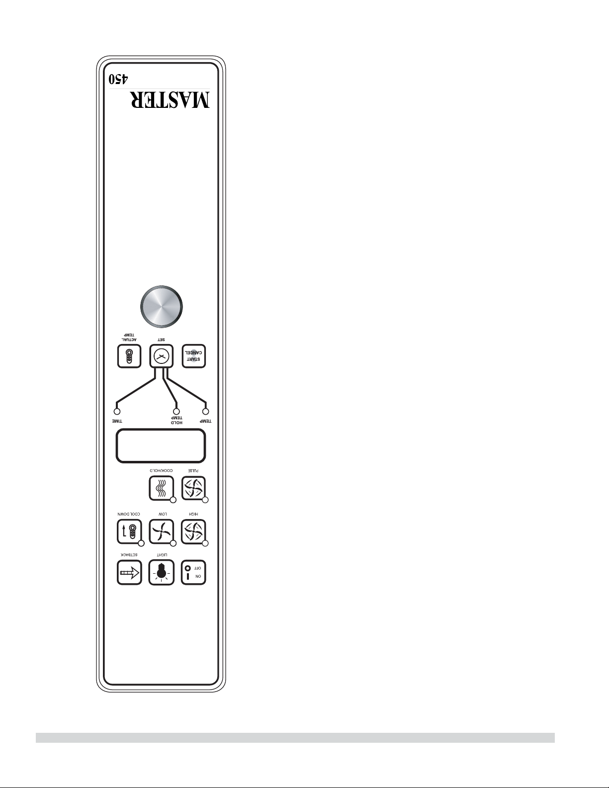
Mettre le bouton en position « OFF » pour annuler le
refroidissement et éteindre le four.
Température
La plage de températures va de 150°F à 500°F (66°C à 250°C)
et est commandée en tournant le cadran de température et
en alignant l’indicateur sur la température souhaitée.
Minuterie
La minuterie est réglée en tournant le bouton dans le
sens horaire pour aligner l’indicateur avec le cycle désiré
de minuterie. La minuterie décompte de 2 minutes à 60
minutes. À la n du cycle de minuterie, un signal sonore
retentit. On arrête le signal sonore en tournant le cadran
dans le sens inverse des aiguilles d’une montre en position
« O », comme indiqué sur le panneau de commande.
NOTA : La minuterie ne commande pas le chau age.
Commande Électronique
Master 450 avec Cuisson et Attente et
Commande Électronique
Master 455 avec Cuisson et Attente et Sonde
Thermique
Modes
En Mode D’arrêt (O )
Lorsque le contrôleur est désactivé, l’a chage indique
« OFF » . Le fait d’appuyer sur la touche ON/OFF active le
contrôleur en mode de démarrage (Start Up).
En Mode De Démarrage (Start Up)
En mode de démarrage, le contrôleur commande le
chau ageselon les derniers réglages e ectués en matière
de température, de durée de cuisson et de vitesse du
ventilateur. Le valeurs par défaut réglées en usine sont de
350°F (177°C), 30 minutes et basse vitesse du ventilateur.
L’ a chage indique « LO » lorsque la température du four est
inférieure à la température sélectionnée. Lorsque l’intérieur
du four atteint la température sélectionnée et que le four est
prêt à être utilisé, l’a chage indique « LOAD » .
REMARQUE: Si la température du four dépasse la
température sélectionnée, l’a chage indique « HI » , et si
la température du four dépasse 575°F (302°C) l’a chage
indique « HELP » et le signal sonore retentit. Ceci est une
fonction de sécurité.
INSTRUCTIONS D’UTILISATION (suite)
Numéro de Pièce 1955203 rév 4 4/15 11
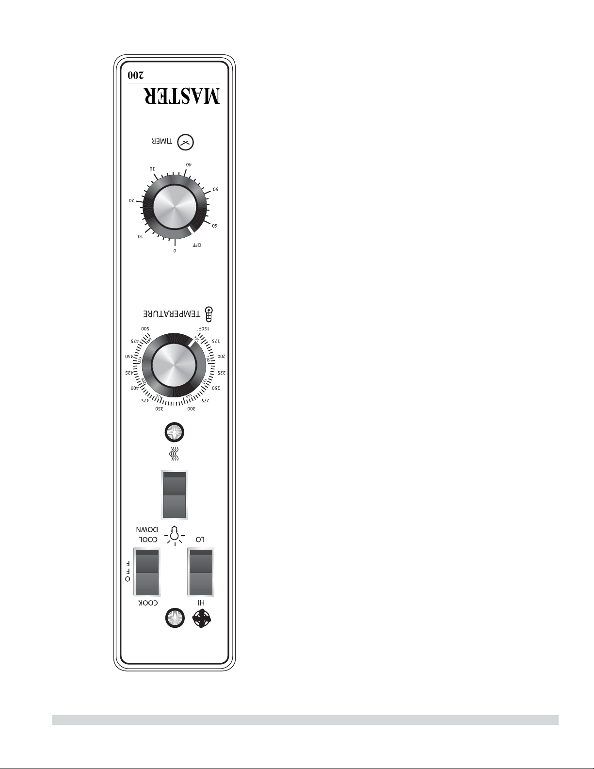
INSTRUCTIONS D’UTILISATION
Commande Transistorisée Master 200 avec
Minuterie Électromécanique
Modes
En mode d’arrêt
Quand le four est éteint, il n’y a aucun voyant ni indicateur.
Démarrage
Mettre le commutateur à bascule COOK/OFF/COOL DOWN
en position « COOK ». Le témoin vert s’allume, indiquant que
le four est sous tension et en mode de cuisson.
Le four commence à chau er pour atteindre la température
réglée sur le cadran du thermostat. Le témoin ambre s’allume
indiquant que le chau age est actif. Ce témoin s’allume et
s’éteint en même temps que le dispositif de chau age pour
maintenir la température réglée.
La porte doit être fermée pour que le four fonctionne en
mode de cuisson. L’ouverture de la porte arrête le dispositif
de chau age. Le moteur et le ventilateur s’arrêtent. Ceci est
une fonction de sécurité.
Vitesse du Ventilateur
La vitesse du ventilateur peut être rapide (1 725 tr/min) ou
lente (1 150 tr/min). La vitesse du ventilateur est commandée
par l’interrupteur à bascule de gauche marqué High (rapide)
et Low (lent).
Éclairage
Les lampes du four sont actionnées en appuyant sur
l’interrupteur d’éclairage du panneau de commande. Il s’agit
d’un interrupteur à rappel et les lampes restent allumées
aussi longtemps que le bouton est maintenu en position de
marche. Les lampes fonctionnement seulement si le four est
branché au réseau électrique.
Refroidissement
Mettre le commutateur à bascule COOK/OFF/COOL DOWN
en position « COOL DOWN » pour activer le ventilateur et le
moteur a n de refroidir l’intérieur du four. La porte doit être
entrouverte pour que le ventilateur et le moteur démarrent.
Le chau age n’est pas actif dans ce mode.
On obtient un refroidissement optimal avec la porte
légèrement ouverte. Le fait d’ouvrir la porte trop grand éteint
le ventilateur et le moteur. Ceci est une caractéristique de
sécurité déposée.
Numéro de Pièce 1955203 rév 4 4/1510
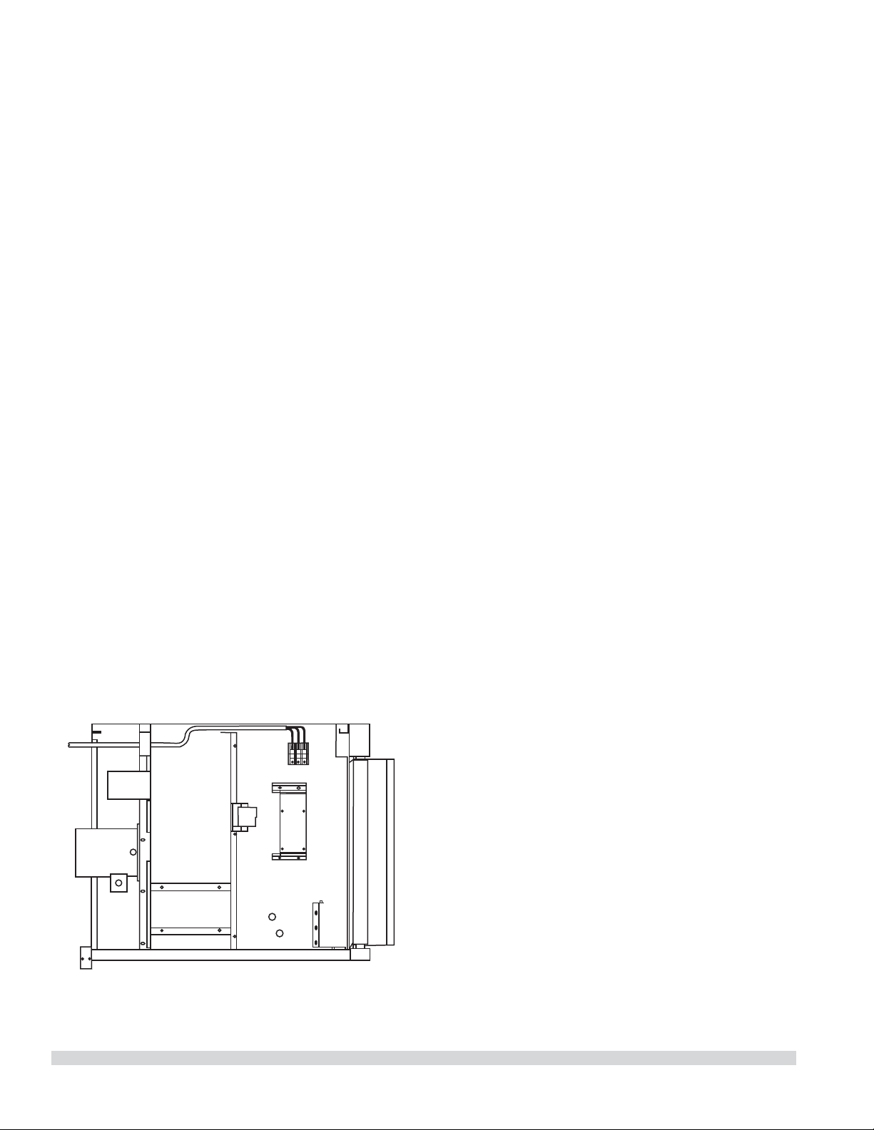
Connexions Électriques
Avant de commencer le branchement électrique, consulter la
plaque signalétique a n de s’assurer que les caractéristiques
électriques de l’appareil correspondent aux caractéristiques
de l’alimentation électrique.
L’installation du câblage doit être faite conformément aux
normes U.L. 197 Commercial Electric Cooking Appliance
Standards, au Code électrique national ou local, ANSI/NFPA
70-1990, ou le Code Électrique Canadien, CSA C22.2 comme
applicables.
1. Dimension du tableau de distribution
2. Protection contre les surcharges
3. Type de l
4. Diamètre des ls
5. Limites de température des ls
6. Méthode de branchement (Câble, conduit, etc.)
Le branchement doit être fait à l’arrière de l’appareil et doit
être relié au bloc de jonction (voir le schéma
ci-dessous). On accède au bloc de jonction en retirant le
couvercle inférieur avant. Il n’est pas nécessaire de retirer
le panneau latéral. Installer un interrupteur général et un
fusible ou disjoncteur séparé avec cet appareil. Utiliser
un conduit souple su samment long entre l’interrupteur
général et l’appareil pour pouvoir le déplacer pour
l’entretien.
La tension d’entrée et le nombre de phases doivent
correspondre à la tension et au nombre de phases de
l’appareil. Un schéma de câblage est xé à l’arrière de
chaque four. Véri er visuellement toutes les connexions
électriques. Mettre sous tension l’alimentation électrique de
l’appareil.
Le four est câblé par commande d’usine d’origine. S’il est
nécessaire le transformer pour une connexion monophasée
ou triphasés, s’il vous plaît se référer à Numéro de Pièce
4533009.
La tension de la ligne d’alimentation et celle de l’appareil
doivent être identiques.
INSTALLATION (suite)
Numéro de Pièce 1955203 rév 4 4/15 9

INSTALLATION
Dégagement d’entrée
• Emballé : 47 po (1194 mm)
• Déballé : 32 ½ po (826 mm)
Conditions d’espace requises
NOTE : Toujours garder un espace su sant pour l’entretien et
l’utilisation.
• Espace de dégagement minimum d’installation près d’un
mur de
combustibles et noncombustibles:
Côtés Côté
commande
Arrière
Modèles À
Une Section
1 po (26 mm) 1 po (26 mm) 3 po (77 mm)
Modèles À
Deux Sections
1 po (26 mm) 2 po (51 mm) 3 po (77 mm)
• Espace de dégagement minimum d’installation à
d’equipements proximité produirant de chaleur élevée:
Côtés Côté
commande
Arrière
Modèles À
Une Section
1 po (26 mm) 6 po (153mm) 3 po (77 mm)
Modèles À
Deux Sections
1 po (26 mm) 6 po (153mm) 3 po (77 mm)
Avis
Éviter d’installer en plus d’autres equipements
(comme les rôtissoires et friteuses) produisant de la
chaleur et de l’air chargé avec la graisse.
• Pour le service, espace de dégagement
(recommandation)
Côté commande
Modèles À
Une Section
12 po (305 mm)
Modèles À
Deux Sections
12 po (305 mm)
NOTE : Installer l’appareil sur roues pour faciliter
le service de réparation dans les endroits étroits.
IMPORTANT : On ne devra pas placer d’objets de grande taille
devant le four, car ils pourraient empêcher la circulation de
l’air à l’avant de l’appareil. Ne pas placer d’objets sur le dessus
arrière du four quand il est utilisé, car cela pourrait obstruer
le système de ventilation. Installer les fours à des endroits
où les panneaux latéraux perforés de la carrosserie ou les
sections de commande ne risquent pas de recevoir de l’eau
des tuyaux de lavage.
Installation des Rôtissoires
Équipées de Roulettes
A. Pour un appareil équipé de roulettes, l’installation sera
e ectuée avec un connecteur conforme à la norme
Connectors for Movable Appliances,
ANSI Z21.69. Des moyens adaptés doivent être prévus
pour limiter les déplacements de l’appareil sans
dépendre du câblage du connecteur.
B. Les roulettes avant de l’appareil sont dotées de freins
a n de limiter les mouvements du four sans dépendre du
câblage du connecteur pour limiter les mouvements de
l’appareil.
C. Un dispositif de retenue peut être xée à l’appareil. Si le
dispositif est débranché, ne pas oublier de le rebrancher
après avoir remis le four dans sa position d’installation
d’origine.
Installation des Modèles à Deux Sections
A. Placer l’insert dans l’ouverture inférieure du pied et
l’enfoncer dans le pied jusqu’à ce qu’il soit en place à
la bride à collier. Fixer les pieds de six pouces (6 po) à
la section inférieure du four. Soulever l’appareil ou le
coucher sur le côté gauche. Placer les pieds avant sur
le four de manière à les aligner avec les quatre (4) trous
des boulons de xation. Fixer les pieds au châssis du
four en utilisant les quatre (4) boulons de 3/8-16 x 3/4 et
les rondelles fournis. Faire la même chose à l’arrière de
l’appareil.
B. Retirer le couvercle inférieur avant de la section
supérieure (situé sous les portes du four). Mettre la
section supérieure en place et aligner les côtés de la
carrosserie et l’arrière de l’appareil. Fixer l’arrière des
appareils ensemble avec la bride d’empilage, en utilisant
huit (6) vis à métaux de 1/4-20, les rondelles de blocage
et les écrous fournis.
C Installer les pièces d’interconnexion des conduits de
fumée en suivant scrupuleusement les instructions
contenues dans l’ensemble d’empilage. Faire très
attention au type de fours à empiler et bien suivre les
instructions correspondantes.
D. Véri er que l’appareil est de niveau dans les quatre sens
en posant un niveau de charpentier ordinaire sur la grille
à l’intérieur du four.
E. Maintenir le dégagement nécessaire par rapport aux
matières combustibles.
ATTENTION : Débrancher les deux fours de l’alimentation
électrique avant toute intervention pour éviter les chocs
électriques!
Numéro de Pièce 1955203 rév 4 4/158
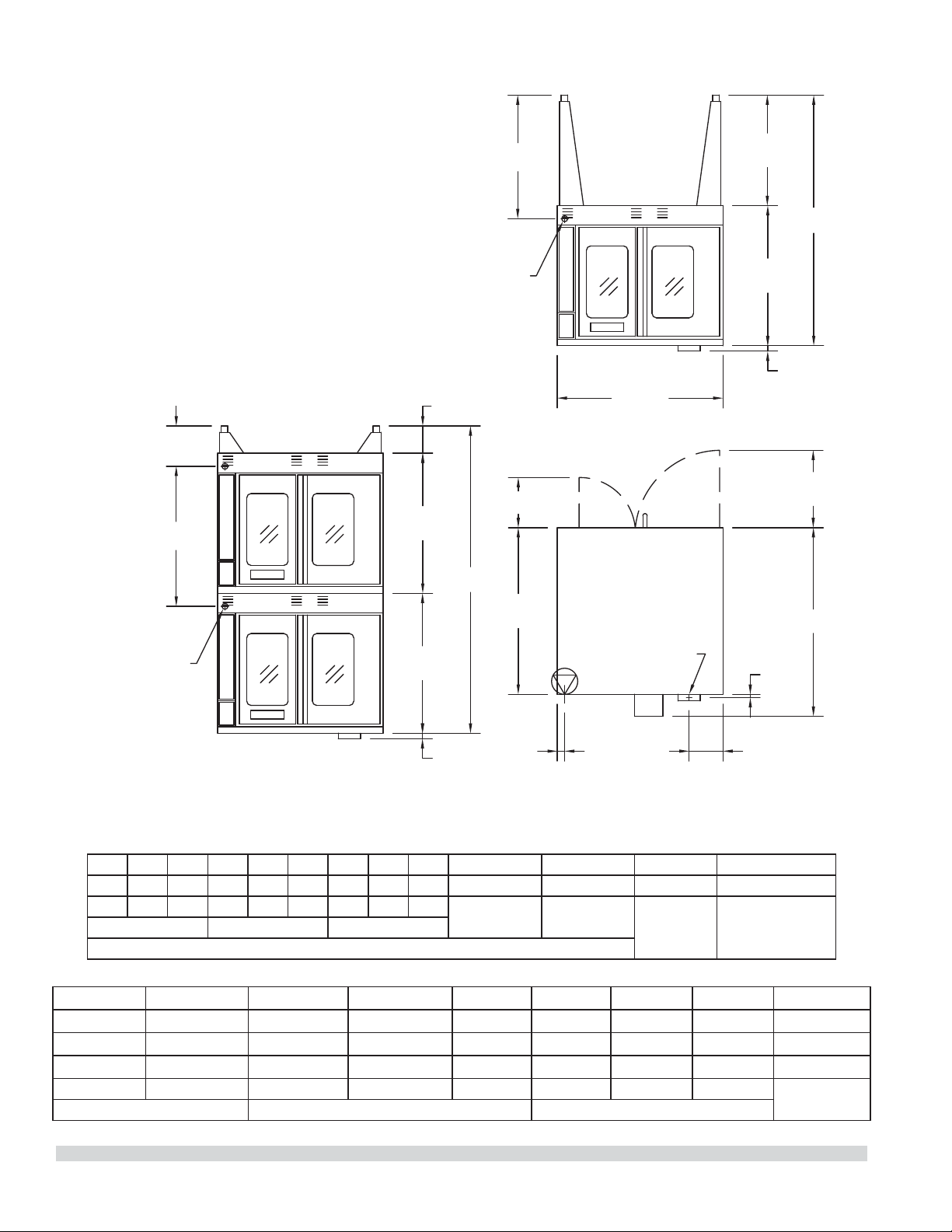
DIMENSIONS ET SPÉCIFICATIONS, MCO ED/ES 10/20 S
7-3/4"
[197mm]
38-1/4"
[972mm]
3/4"
[19mm]
17-3/4"
[451mm]
38"
[965mm]
32-1/8"
[816mm]
25-3/8"
[645mm]
1-1/4"
[32mm]
32-1/8"
[816mm]
32-1/8"
[816mm]
6-1/4"
[159mm]
1-1/4"
[32mm]
11-1/2"
[292mm]
28-3/8"
[721mm]
1-11/16"
[43mm]
9-1/4"
[235mm]
32-1/8"
[816mm]
P
H
VUE DE DESSUS
H
FUMÉE: 2-3/8" x 5"
[60mm x 127mm]
ENTRÉE
DE CÂBLE
ARRIÈRE
ENTRÉE
DE CÂBLE
ARRIÈRE
VUE AVANT
DU FOUR
À DEUX SECTIONS
VUE AVANT
DU FOUR
À UNE SECTION
Les spéci cations électriques standard
comprennent les exigences du moteur. Moteur
3/4 H.P., 2 vitesses, 1140/950 et 1725/1440 tr/mn,
60/50Hz.
Modèle
Dimensions Intérieures (par four) Dimensions Extérieures Informations d’expédition
L:Po(mm) H:Po(mm)
P:Po(mm)
L:Po(mm) H:Po(mm) * P:Po(mm) Lb/Kg Volume
MCO-ES-10-S
29(436) 24(610) 24(610) 38(965) 57-1/2(1416)
41-1/4 (1048)
515/230 64
MCO-ES-20-S
29(436) 24(610) 24(610) 38(965) 70-1/2(1791)*
41-1/4 (1048)
1030/465 128
MCO-ED-10-S
29(436) 24(610) 28(711) 38(965) 57-1/2(1416)
44-1/2(1130)
545/245 64
MCO-ED-20-S
29(436) 24(610) 28(711) 38(965) 70-1/2(1791)*
44-1/2(1130)
1090/490 128
* Hauteur avec ou sans les roulettes standard. La hauteur avec les roulettes à pro l bas (double section) est de 68-1/2po (1740 mm).
Modèle**
Puissance
Totale kW
Ampérage Nominal par Ligne (Comprend le Moteur du Ventilateur de 3/4 Hp)
208v/1Ph 240V/1Ph
208V/3Ph 240V/3Ph 460V/3Ph
XYZXYZXYZ
MCO-ES-10-S 10.4 50 43 30 30 28 26 26 24 14 14 13
MCO-ED-10-S 10.4 50 43 30 30 38 26 26 24 14 14 13
**Remarque : Les fours à deux sections sont livrés avec des connexions d’alimentation individuelles.
Numéro de Pièce 1955203 rév 4 4/15 7
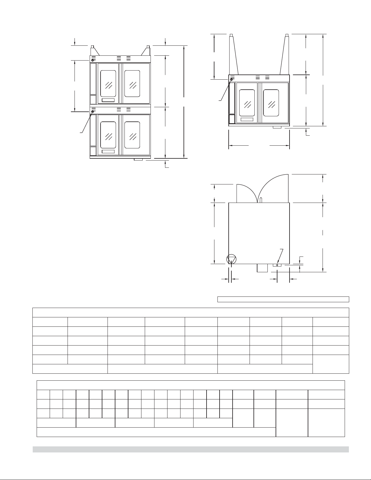
DIMENSIONS ET SPÉCIFICATIONS, MCO ED/ES 10/20
7-3/4"
[197mm]
MCO-ES
41-1/4"
[1048mm]
MCO-ED
44-1/2"
[1130mm]
38-1/4"
[972mm]
3/4"
[19mm]
17-3/4"
[451mm]
VUE DE DESSUS
38"
[965mm]
32-1/8"
[816mm]
57-1/2"
[1461mm]
25-3/8"
[645mm]
VUE AVANT
DU FOUR
À UNE SECTION
1-1/4"
[32mm]
32-1/8"
[816mm]
32-1/8"
[816mm]
70-1/2"
[1791mm]
6-1/4"
[159mm]
1-1/4"
[32mm]
VUE AVANT
DU FOUR
À DEUX SECTIONS
ENTRÉE
DE CÂBLE
ARRIÈRE
11-1/2"
[292mm]
1-11/16"
[43mm]
28-3/8"
[721mm]
32-1/8"
[816mm]
9-1/4"
[235mm]
FUMÉE: 2-3/8" x 5"
[60mm x 127mm]
ENTRÉE
DE CÂBLE
ARRIÈRE
Modèle*
Puissance
Totale kW
Ampérage Nominal par Ligne (Comprend le Moteur du Ventilateur de 3/4 Hp)
208V/
1Ph
240V/
IPh
208V/3Ph 240V/3Ph 460V/3Ph 380V/3Ph** 415V/3Ph
XYZXYZXYZXYZXYZ
MCO-ES-10 10.4 50 43 30 30 28 26 26 24 14 14 13 15 13 13 16 14 14
MCO-ED-10 10.4 50 43 30 30 28 26 26 24 14 14 13 15 13 13 16 14 14
**La-puissance totale pour les modèles 380 V triphasés est de 9 kW.
Modèle
Dimensions Intérieures (par Four) Dimensions Extérieures Informations d’expédition
L:Po(mm) H:Po(mm) P:Po(mm) L:Po(mm) H:Po(mm) D:Po (mm) Lb/Kg Volume
MCO-ES-10 29 (736) 24 (610) 24 (610) 38 (965) 57-1/2 (1461) 41-1/4 (1048) 515/230 64
MCO-ES-20 29 (736) 24 (610) 24 (610) 38 (965) 70-1/2 (1791)* 41-1/4 (1048) 1030/465 128
MCO-ED-10 29 (736) 24 (610) 28 (711) 38 (965) 57-1/2 (1461) 44-1/2(1130) 545/245 64
MCO-ED-20 29 (736) 24 (610) 28 (711) 38 (965) 70-1/2 (1791)* 44-1/2(1130) 1090/490 128
* Hauteur avec ou sans les roulettes standard. La hauteur avec les roulettes à pro l bas (double section) est de 68-1/2po (1740 mm).
Les spéci cations électriques standard comprennent les
exigences du moteur. Moteur 3/4 HP, 2 vitesses, 1140/950 et
1725/1440 tr/mn, 60/50Hz.
Remarque : Les fours à deux sections sont livrés avec des
connexions d’alimentation individuelles.
AVIS: Modèles CE fabriqués jusqu’à Octobre, 2014.
Numéro de Pièce 1955203 rév 4 4/156
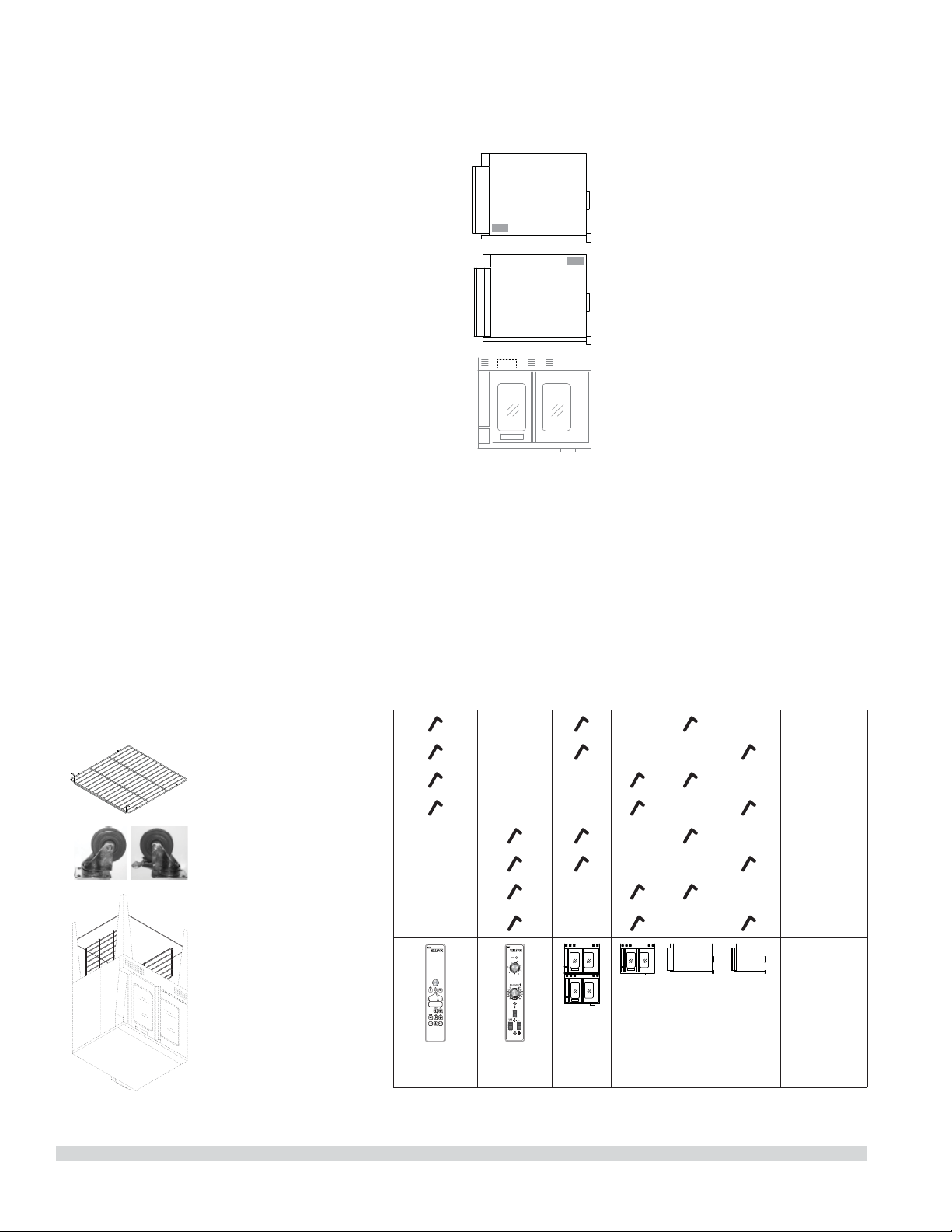
GÉNÉRALITÉS
Références des modèles
Modèles prof.
standard
grande
prof.
une
section
deux
sections
Master
200
commande
commande
électronique
MCO-ES-10S
MCO-ED-10S
MCO-ES-20S
MCO-ED-20S
MCO-ES-10
MCO-ED-10
MCO-ES-20
MCO-ED-20
Garantie
Visitez www.Garland-Group.com pour voir ou télécharger une copie de
votre garantie.
Plaque signalétique
Lors des communications avec le fabricant ou votre centre de services
local autorisé par le fabricant concernant des problèmes relatifs au
service ou pour les pièces de remplacements, assurez-vous d’avoir les
informations concernant le numéro du modèle de l’appareil (incluant les
lettres et numéros du pré xe et du su xe) ainsi que le numéro de série
correspondant à la garantie.
Fours construits avant 31-Mars-2011
• La plaque signalétique est fixée
à l’intérieur de la couverture
inférieure.
Fours construits entre 01-Avril-2011
and 02-Février-2015
• La plaque signalétique se trouve sur
le coin inférieur arrière du panneau
latéral gauche.
Fours construits après 02-Février-2015
• La plaque signalétique se trouve sur
le coin supérieur avant du panneau
latéral gauche.
Accessoires
• base ouverte (en acier
inoxydable) avec
étagère et des guides
pour les grilles du
four (Modèles À Une
Section)
• roulettes, ensemble de
quatre
• la grille du four,
supplémentaire
• lèchefrite, amovible
Numéro de Pièce 1955203 rév 4 4/15 5

CETTE PAGE EST LAISSÉE BLANCHE INTENTIONNELLEMENT

TABLE DES MATIÈRE
INFORMATIONS IMPORTANTES . . . . . . . . . . . . 2
GÉNÉRALITÉS. . . . . . . . . . . . . . . . . . . . . . . . . . . . . 5
Références des modèles . . . . . . . . . . . . . . . . . . . . . . . . . 5
Garantie . . . . . . . . . . . . . . . . . . . . . . . . . . . . . . . . . . . . . . . . 5
Plaque signalétique . . . . . . . . . . . . . . . . . . . . . . . . . . . . . 5
Accessoires . . . . . . . . . . . . . . . . . . . . . . . . . . . . . . . . . . . . . . 5
DIMENSIONS ET SPÉCIFICATIONS, MCO ED/
ES 10/20 . . . . . . . . . . . . . . . . . . . . . . . . . . . . . . . . . 6
DIMENSIONS ET SPÉCIFICATIONS, MCO ED/
ES 10/20 S . . . . . . . . . . . . . . . . . . . . . . . . . . . . . . . . 7
INSTALLATION . . . . . . . . . . . . . . . . . . . . . . . . . . . . 8
Dégagement d’entrée . . . . . . . . . . . . . . . . . . . . . . . . . . . 8
Conditions d’espace requises . . . . . . . . . . . . . . . . . . . . 8
Installation des Rôtissoires
Équipées de Roulettes . . . . . . . . . . . . . . . . . . . . . . . . . . . 8
Installation des Modèles à Deux Sections . . . . . . . . . 8
INSTRUCTIONS D’UTILISATION . . . . . . . . . . . 10
Commande Transistorisée Master 200 avec
Minuterie Électromécanique . . . . . . . . . . . . . . . . . . . . 10
Modes . . . . . . . . . . . . . . . . . . . . . . . . . . . . . . . . . . 10
Vitesse du Ventilateur . . . . . . . . . . . . . . . . . . . 10
Éclairage . . . . . . . . . . . . . . . . . . . . . . . . . . . . . . . 10
Refroidissement. . . . . . . . . . . . . . . . . . . . . . . . . 10
Température . . . . . . . . . . . . . . . . . . . . . . . . . . . . 11
Minuterie . . . . . . . . . . . . . . . . . . . . . . . . . . . . . . . 11
Commande Électronique
Master 450 avec Cuisson et Attente et Commande
Électronique
Master 455 avec Cuisson et Attente et Sonde
Thermique . . . . . . . . . . . . . . . . . . . . . . . . . . . . . . . . . . . . . 11
Modes . . . . . . . . . . . . . . . . . . . . . . . . . . . . . . . . . . 11
Touches du Contrôleur . . . . . . . . . . . . . . . . . . 12
Fahrenheit/Celsius. . . . . . . . . . . . . . . . . . . . . . . 13
Utilisation des Commandes . . . . . . . . . . . . . 13
Fonctionnement en Mode Cuisson-attente 13
Fonctionnement avec la Sonde Thermique 13
Réglage de la fonction Setback
(retour au point de consigne) . . . . . . . . . . . . 14
Commande Électronique Programmable
de la Série Master 475 . . . . . . . . . . . . . . . . . . . . . . . . . . 14
Cuisson Manuelle . . . . . . . . . . . . . . . . . . . . . . . 14
Cuisson Manuelle à l’aide
de la Fonction Cook-N-Hold
(Cuisson et Maintien au Chaud) . . . . . . . . . . 15
Programmation des Touches Produit
(Master 475). . . . . . . . . . . . . . . . . . . . . . . . . . . . . 15
Cuisson avec Utilisation des Touches Produit
(Master 475). . . . . . . . . . . . . . . . . . . . . . . . . . . . . 16
Véri cation du Temps de Maintien au Chaud
(Master 475). . . . . . . . . . . . . . . . . . . . . . . . . . . . . 16
Sélection De L’a chage En Degrés Fahrenheit
Ou Celsius (Master 475) . . . . . . . . . . . . . . . . . . 16
Cuisson avec la Minuterie de Niveau
(Master 475). . . . . . . . . . . . . . . . . . . . . . . . . . . . . 16
RECOMMANDATIONS D’UTILISATION ET
PRÉCAUTIONS GÉNÉRALES DE SÉCURITÉ . . 18
PROBLÈMES/SOLUTIONS . . . . . . . . . . . . . . . . . 19
GUIDE DE CAISSON . . . . . . . . . . . . . . . . . . . . . . 20
CUISSON ET MAINTIEN AU CHAUD . . . . . . . . 21
ENTRETIEN ET NETTOYAGE . . . . . . . . . . . . . . . 22
Période de Rodage . . . . . . . . . . . . . . . . . . . . . . . . . . . . . 22
Nettoyage Extérieur . . . . . . . . . . . . . . . . . . . . . . . . . . . . 22
Maintenance de la Zone du Ventilateur . . . . . . . . . . 22
Entretien du Moteur . . . . . . . . . . . . . . . . . . . . . . . . . . . . 23
Numéro de Pièce 1955203 rév 4 4/15 3

L’attention des utilisateurs est attirée sur le fait que l’entretien et les réparations doivent être e ectués par un agent
d’entretien autorisé par Garland utilisant des pièces de rechange d’origine Garland. Garland n’aura aucune obligation
en ce qui concerne n’importe quel produit mal installé, réglé, utilisé ou qui n’aurait pas été entretenu conformément aux
codes nationaux et locaux ou aux instructions d’installation fournies avec le produit ou n’importe quel produit dont le
numéro de série aurait été mutilé, oblitéré ou supprimé ou qui aurait été modi é ou réparé avec des pièces non autorisées
ou par des agents d’entretien non autorisés. Pour obtenir la liste des agents de service autorisés, consulter le site web
de Garland à : http://www.garland-group.com. Les renseignements contenus dans le présent document (y compris la
conception et les spéci cations des pièces) peuvent être remplacés ou modi és sans préavis.
POUR VOTRE SÉCURIT:
NE PAS STOCKER NI UTILISER D’ESSENCE
OU D’AUTRES VAPEURS OU LIQUIDES
INFLAMMABLES À PROXIMITÉ DE CET
APPAREIL OU DE TOUT AUTRE APPAREIL
AVERTISSEMENT
UNE INSTALLATION, DES RÉGLAGES, DES
MODIFICATIONS, DES RÉPARATIONS
OU UN ENTRETIEN MAL FAITS PEUVENT
CAUSER DES DOMMAGES MATÉRIELS,
DES BLESSURES OU LA MORT. LIRE
SOIGNEUSEMENT LES INSTRUCTIONS
D’INSTALLATION, D’UTILISATION ET
D’ENTRETIEN AVANT D’INSTALLER OU DE
RÉPARER L’ÉQUIPEMENT.
LIRE TOUTES LES SECTIONS DU PRÉSENT
MANUEL ET LE CONSERVER POUR S’Y REPORTER
ULTÉRIEUREMENT.
CE PRODUIT A ÉTÉ HOMOLOGUÉ EN TANT
QU’ÉQUIPEMENT PROFESSIONNEL DE CUISSON
ET DOIT ÊTRE INSTALLÉ PAR DU PERSONNEL
PROFESSIONNEL TEL QUE SPÉCIFIÉ.
L’INSTALLATION ET LES CONNEXIONS
DEVRONT ÊTRE CONFORMES AUX CODES EN
VIGUEUR: AU CANADA – LE CODE CANADIEN
DE L’ÉLECTRICITÉ, PARTIE 1 ET/OU LES CODES
LOCAUX. AUX É.-U. – LE NATIONAL ELECTRICAL
CODE ANSI / NFPA – ÉDITION EN VIGUEUR.
VÉRIFIER QUE L’ALIMENTATION ÉLECTRIQUE
EST CONFORME AUX CARACTÉRISTIQUES
ÉLECTRIQUES FIGURANT SUR LA PLAQUE
SIGNALÉTIQUE.
INFORMATIONS IMPORTANTES
AVERTISSEMENT
Ce produit contient des produits chimiques reconnus par l’état de Californie comme causant
le cancer et/ou des malformations congénitales ou d’autres problèmes de reproduction.
L’installation et l’entretien de ce produit peut vous exposer aux poussières de laine de
verre/fibres céramiques. L’inhalation de ces particules de laine de verre ou de fibres céramiques est reconnue par l’état
de Californie comme causant le cancer.
AVIS
Modèles CE, discontinué, fabriqués jusqu’à Octobre, 2014.
Panne d’électricité
En cas de panne d’électricité, ne pas essayer de faire fonctionner ce
four.
Numéro de Pièce 1955203 rév 4 4/152
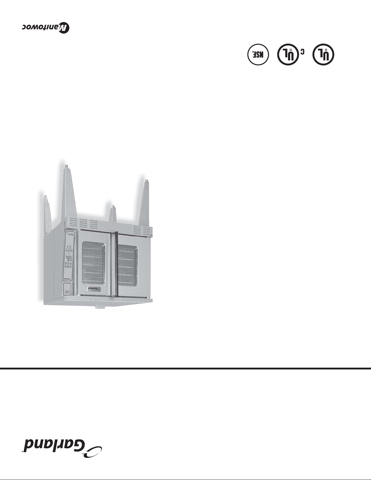
Numéro de Pièce 1955203 rév 4 4/15
Manuel d'Installation et d'utilisation
Ce manuel est mis à jour au fur et à mesure que de nouvelles informations sont disponibles et que de nouveaux modèles
sont commercialisés. Pour obtenir la dernière mise à jour du manuel, visitez notre site Web.
Du Four Électrique À Convection
« The Master »
MCO-ES-10
modèles
MCO-ES-10S
MCO-ED-10S
MCO-ES-20S
MCO-ED-20S
MCO-ES-10
MCO-ED-10
MCO-ES-20
MCO-ED-20

