Loading ...
Loading ...
Loading ...
30
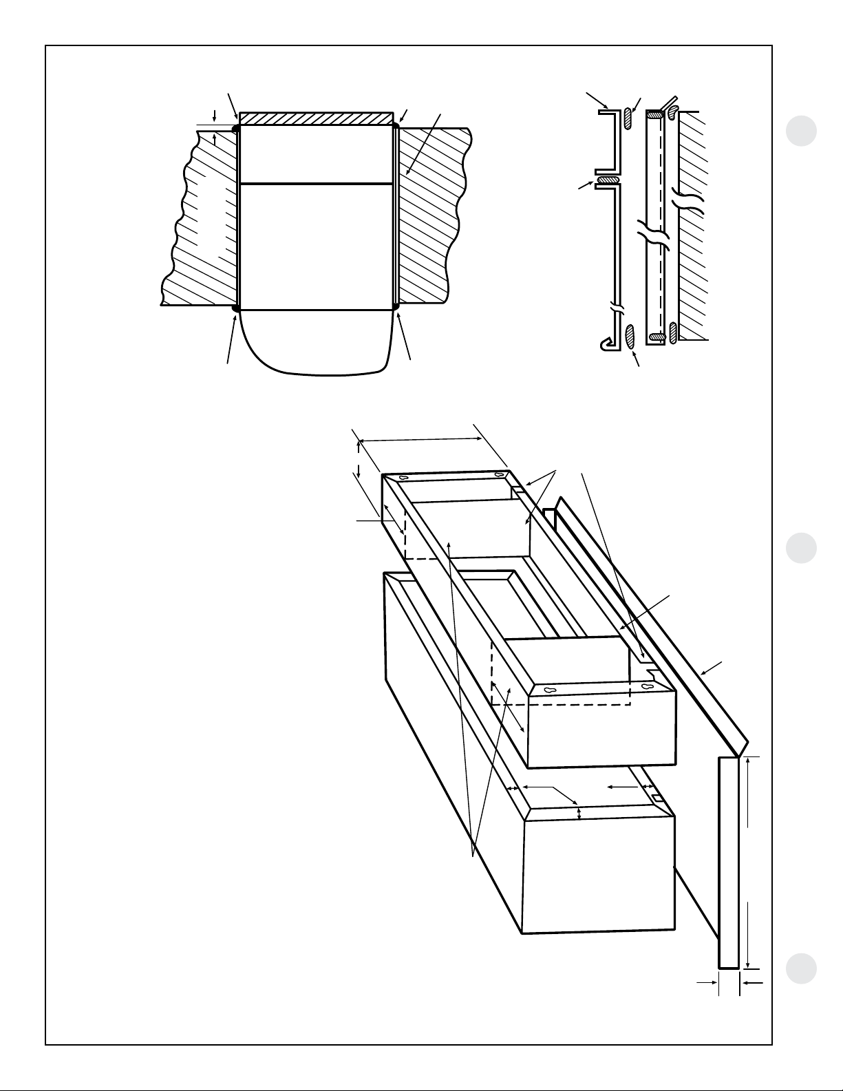
METAL CASE EXTENSION FOR WALLS DEEPER THAN 13-1/8" (11-1/8" WITH SUB-BASE)
Field fabricated – ge recommends the use of one of the deeper RAB71 wall cases offered as special order items.
CAULK*
SPLITTER BETWEEN
AIR INTAKE AND
DISCHARGE
Zoneline units can be installed in walls of greater
depth than the wall case. Where the case recession is
less than 3" and where it is possible to waterproof the
exposed sides and top of the opening, the suggested
procedure is to apply a flashing to the bottom of the
wall case as shown on page 31. Where waterproofing
is questionable or not possible, or for installations in
walls of greater depth, the following is a suggested
application procedure. It involves the field fabrication of
a case extension. Since the wall case is a water bearing
container, the extension likewise must also be water
bearing and the connection between the two must be
watertight. The case extension must contain splitters to
prevent recirculation of the outdoor air circuit.
1. The case extension is field fabricated. The extension
depth “D” should allow for a minimum outdoor
projection of 1/4". This allows for room cabinet
clearance to the finished wall and ample surfaces
to apply sealant or caulking for a tight weather seal
between the completed wall case/extension assembly
and the wall opening. It is recommended that the
extension be painted and corner and lap joints be
additionally sealed with a quality grade sealant.
2. The wall case and extension should be connected
prior to installation in the wall opening. A quality
grade sealant should be applied to all four (4) butting
flanges. Use bolts and nuts or oversized self tapping
screws (driven from the wall case to the extension)
to attach the two assemblies. Clean all drain holes of
excess sealant. The assembly must be free draining.
3. Install flashing, using a quality grade sealant between
the flashing and wall as shown in section A-A below.
4. Install the wall case/extension assembly following
procedures described for a standard installation.
See diagrams below. The assembly should be sealed
or caulked to the wall around all four sides both
outdoors and indoors.
NOTE: The wall case/extension assembly should
be level.
5. Suggested materials for case extension and flashing
should be non-ferrous metals. Minimal acceptable
material: Galvanized G-90 painted.
SEALANT - ALL
FOUR (4) FLANGES
6-1/4" ± 1/4"
AS REQ'D.
CUT DRAIN SLOTS
IN BOTH FLANGES
(FOUR REQUIRED)
TO MATCH DRAIN
HOLES IN RAB71/77
FLANGES AND
DRAIN HOLE
LOCATIONS
SAME AS ON
WALL CASE
1" WIDE
45° DRIP LIP
FLASHING (FIELD SUPPLIED)
13-3/4" + D"
2" MIN.
D
10-5/8" ± 1/4"
CAULK*
CAULK*
CAULK*
WALL -
ANY
CONSTRUCTION
RAB71/77ROOM
CABINET
CASE
EXT.
SEE DETAIL
SECTION A-A
*Caulk around perimeter of wall case all four sides
where it joins the building - Interior and Exterior.
EXTENSION
ALL 4 FLANGES
WALL CASE
ALL 4
SIDES
WALL
FLASHING
ALL 4
SIDES
SECTION A-A
BASEPAN/FLANGE DESIGN
SHOWING SEALANT LOCATIONS.
1/4" MIN.
RAB71/77
WALL CASE
1-1/2"
(4 SIDES)
EXTENSION
(FIELD
SUPPLIED)
Loading ...
Loading ...
Loading ...