Decorative Product: Not for use as a heating appliance.
ADD MANUAL TITLE
Wolf Steel Ltd., 24 Napoleon Rd., Barrie, ON, L4M 0G8 Canada / 103 Miller Drive, Crittenden, Kentucky, USA, 41030
Phone 1 (866) 820-8686 • www.napoleonfireplaces.com • hearth@napoleonproducts.com
CERTIFIED TO THE CANADIAN AND AMERICAN NATIONAL STANDARDS:
ANSI Z21.97 AND CSA 2.41 FOR OUTDOOR DECORATIVE GAS APPLIANCES
INSTALLER:
Leave this manual with the appliance
CONSUMER:
Retain this manual for future reference
ADD PRODUCT CODE HERE (TRADE GOTHIC LT STD FONT)
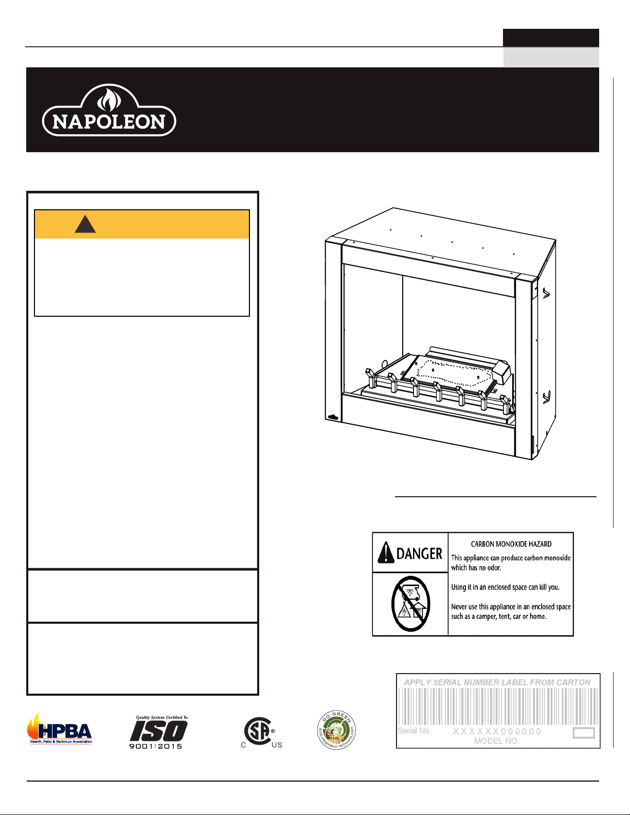
PROPANE GAS MODELS: GSS36CFP
PRODUCT NAME™
ADD ____ ILLUSTRATED
ADD PRODUCT IMAGE
SAFETY INFORMATION
- Do not store or use gasoline or other
flammable vapors and liquids in the vicinity of this
or any other appliance.
- An LP-cylinder not connected for use shall not be
stored in the vicinity of this or any other appliance.
- WHAT TO DO IF YOU SMELL GAS:
• Do not try to light any appliance.
• Shut off gas to the appliance.
• Do not touch any electrical switch; do not use
any phone in your building.
• Immediately call your gas supplier from a neigh-
bour’s phone. Follow the gas supplier’s instruc-
tions.
• If you cannot reach your gas supplier, call the fire
department.
- Installation and service must be performed
by a qualified installer, service agency, or the
supplier.
This appliance is only for use with the type of gas
indicated on the rating plate. This appliance is
not convertible for use with other gases, unless a
certified kit is used.
If the information in these instructions are not
followed exactly, a fire or explosion may result
causing property damage, personal injury or
loss of life. Read the installation, operating and
maintenance instructions thoroughly before
installing or servicing this equipment.
WARNING
!
ENGLISH
$10.00
INSTALLATION AND
OPERATION MANUAL
Riverside™ Series
(GSS36CF Illustrated)
NATURAL GAS MODELS: GSS36CFN
FOR OUTDOOR USE ONLY
IF INSTALLATION + OPERATION, ADD SERIAL
NUMBER LABEL HERE
IF SEPARATE MANUALS, ADD “PLACE
BARCODE LABEL ON THE OWNER’S MANUAL”
FRENCH
PG. 35
W415-1796 / A / 05.17.18

• This appliance is hot when operated and
can cause severe burns if contacted.
• Any changes or alterations to this
appliance or its controls can be
dangerous and is prohibited.
• Do not operate appliance before reading and
understanding operating instructions. Failure
to operate appliance according to operating
instructions could cause fi re or injury.
• Ensure the glass door is opened or removed
when lighting the pilot for the fi rst time and
when the gas supply has run out.
• Risk of fi re or asphyxiation do not operate
appliance with fi xed glass removed and never
obstruct the front opening of the appliance.
• Objects placed in front of the appliance must
be kept a minimum of 4 feet (1.22m) from the
front face of the appliance.
• Do not connect 110 volts to the control valve,
with the exception of models; GSST8 and GT8.
• Risk of burns. The appliance should be turned off and cooled before servicing.
• Do not install damaged, incomplete or substitute components.
• Risk of cuts and abrasions. Wear protective gloves, protective footwear, and safety glasses during
installation. Sheet metal edges may be sharp.
• Do not burn wood or other materials in this appliance.
• Provide adequate ventilation and combustion air. Provide adequate accessibility clearance for servicing
and operating the appliance. Never obstruct the front opening of the appliance.
• The appliance area must be kept clear and free from combustible materials, gasoline and other
fl ammable vapors and liquids.
• High pressure will damage valve. Disconnect gas supply piping before pressure testing gas line at
test pressures above 1/2 psig. Close the manual shut-off valve before pressure testing gas line at test
pressures equal to or less than 1/2 psig (35mb).
• The appliance must not be operated at temperatures below freezing (32°F / 0°C). Allow the appliance
to warm to above freezing prior to operation, with the exception of models; GSS36, GSS42; these
appliances are suitable for 0°F / -18°C.
• Children and adults should be alerted to hazards of high surface temperature and should stay
away to avoid burns or clothing ignition.
• Young children should be carefully supervised when they are in the same room as the
appliance. Toddlers, young children and others may be susceptible to accidental contact
burns. A physical barrier is recommended if there are at risk individuals in the house. To
restrict access to an appliance or stove, install an adjustable safety gate to keep toddlers,
young children and other at risk individuals out of the room and away from hot surfaces.
• Clothing or other fl ammable material should not be placed on or near the appliance.
• Due to high temperatures, the appliance should be located out of traffi c and away from
furniture and draperies.
• Furniture or other objects must be kept a minimum of 4 feet (1.22m) away from the front of the appliance.
• Ensure you have incorporated adequate safety measure to protect infants/toddlers from touching hot
surfaces.
• Even after the appliance is off, it will remain hot for an extended period of time.
• Check with your local hearth specialty dealer for safety screens and hearth guards to protect children
from hot surfaces. These screens and guards must be fastened to the fl oor.
• Any safety screen, guard or barrier removed for servicing the appliance, must be replaced prior
to operating the appliance.
• It is imperative that the control compartments, burners and circulating blower and its passageway in the
appliance and venting system are kept clean. The appliance and its venting system should be inspected
before use and at least annually by a qualifi ed service person. More frequent cleaning may be required
due to excessive lint from carpeting, bedding material, etc. The appliance area must be kept clear and
free from combustible materials, gasoline and other fl ammable vapors and liquids.
• If the appliance shuts off, do not re-light until you provide fresh air. If appliance keeps shutting off, have it
serviced. Keep burner and control compartment clean.
• Under no circumstances should this appliance be modifi ed.
LA VITRE CHAUDE CAUSERA
DES BRÛLURES.
NE PAS TOUCHER LA VITRE
AVANT QU’ELLE AIT REFROIDI.
NE JAMAIS LAISSER LES
ENFANTS TOUCHER LA VITRE.
HOT GLASS WILL CAUSE
BURNS.
DO NOT TOUCH GLASS UNTIL
COOLED.
NEVER ALLOW CHILDREN TO
TOUCH GLASS.
!
DANGER
!
AVERTISSEMENT
A barrier designed to reduce the risk of burns from the
hot viewing glass is provided with this appliance and
shall be installed for the protection of children and other
at-risk individuals.
Une barriére conçu à réduire le risque de brûlures
causées par le verre chaud est fourni avec l’appareil et
sera installé pour la protection des enfants et d’autres
personnes à risque.
3.1B
!
WARNING
!
WARNING
• Do not allow wind or fans to blow directly into the appliance. Avoid any drafts that alter burner fl ame
patterns.
• Do not use a blower insert, heat exchanger insert or other accessory not approved for use with this
appliance.
• This appliance must not be connected to a chimney fl ue pipe serving a separate solid fuel burning
appliance.
• Do not use this appliance if any part has been under water. Immediately call a qualifi ed service technician
to inspect the appliance and to replace any part of the control system and any gas control which has
been under water.
• Do not operate the appliance with the glass door removed, cracked or broken. Replacement of the glass
should be done by a licensed or qualifi ed service person, if equipped.
• Do not strike or slam shut the appliance glass door, if equipped.
• Only doors / optional fronts certifi ed with the appliance are to be installed on the appliance.
• Keep the packaging material out of reach of children and dispose of the material in a safe manner. As
with all plastic bags, these are not toys and should be kept away from children and infants.
• Carbon or soot should not occur in a vent free appliance as it can distribute into the living area of your
home. If you notice any signs of carbon or soot, immediately turn off your appliance and arrange to have
it serviced by a qualifi ed technician before operating it again.
• If equipped, the screen must be in place (closed) when the appliance is in operation.
• When equipped with pressure relief doors, they must be kept closed while the appliance is operating
to prevent exhaust fumes containing carbon monoxide, from entering into the home. Temperatures of
the exhaust escaping through these openings can also cause the surrounding combustible materials to
overheat and catch fi re.
• Carbon monoxide poisoning may lead to death; early signs of carbon monoxide poisoning resemble
the fl u, with headache, dizziness and/or nausea. If you have these signs, the heater may not be working
properly. Get fresh air at once! Have heater serviced. Some people; pregnant women, persons with heart
or lung disease, anemia, those under the infl uence of alcohol, those at high altitudes are more affected by
carbon monoxide than others. Failure to keep the primary air opening(s) of the burner(s) clean may result
in sooting and property damage.
• As with any combustion appliance, we recommend having your appliance regularly inspected and
serviced as well as having a Carbon Monoxide Detector installed in the same area to defend you and
your family against Carbon Monoxide.(Not applicable for outdoor appliances).
• Ensure clearances to combustibles are maintained when building a mantel or shelves above the
appliance. Elevated temperatures on the wall or in the air above the appliance can cause melting,
discolouration or damage to decorations, a T.V. or other electronic components.
• For appliances equipped with a safety barrier; the barrier is designed to reduce the risk of
burns from the hot viewing glass is provided with this appliance and shall be installed. If the
barrier becomes damaged, the barrier shall be replaced with the manufacturer’s barrier for this
appliance.
• Installation and repair should be done by a qualifi ed service person. The appliance should be
inspected before use and at least annually by a professional service person. More frequent
cleaning may be required due to excessive lint from carpeting, bedding material, etc. It
is imperative that control compartments, burners and circulating air passageways of the
appliance be kept clean.
• For outdoor products only: this appliance must not be installed indoors or within any structure that
prevents or inhibits the exhaust gases from dissipating in the outside atmosphere.
• If applicable, the millivolt version of this appliance uses and requires a fast acting thermocouple. Replace
only with a fast acting thermocouple supplied by Wolf Steel Ltd.
!
WARNING
!
Disconnect the appliance main gas valve/control
from the supply piping when pressure testing that
system at pressures in excess of 1/2 psi (3.5 kPa).
Isolate the appliance with it’s shut off valve during
any pressure testing of the supply piping at
pressures equal to or less than 1/2 psi (3.5 kPa).
FIRE RISK HAZARD / DELAYED IGNITION
High supply pressure will damage the valve / controls.
W415-1796 / A / 05.17.18
EN
2
safety information
• This appliance is hot when operated and
can cause severe burns if contacted.
• Any changes or alterations to this
appliance or its controls can be
dangerous and is prohibited.
• Do not operate appliance before reading and
understanding operating instructions. Failure
to operate appliance according to operating
instructions could cause fi re or injury.
• Ensure the glass door is opened or removed
when lighting the pilot for the fi rst time and
when the gas supply has run out.
• Risk of fi re or asphyxiation do not operate
appliance with fi xed glass removed and never
obstruct the front opening of the appliance.
• Objects placed in front of the appliance must
be kept a minimum of 4 feet (1.22m) from the
front face of the appliance.
• Do not connect 110 volts to the control valve,
with the exception of models; GSST8 and GT8.
• Risk of burns. The appliance should be turned off and cooled before servicing.
• Do not install damaged, incomplete or substitute components.
• Risk of cuts and abrasions. Wear protective gloves, protective footwear, and safety glasses during
installation. Sheet metal edges may be sharp.
• Do not burn wood or other materials in this appliance.
• Provide adequate ventilation and combustion air. Provide adequate accessibility clearance for servicing
and operating the appliance. Never obstruct the front opening of the appliance.
• The appliance area must be kept clear and free from combustible materials, gasoline and other
fl ammable vapors and liquids.
• High pressure will damage valve. Disconnect gas supply piping before pressure testing gas line at
test pressures above 1/2 psig. Close the manual shut-off valve before pressure testing gas line at test
pressures equal to or less than 1/2 psig (35mb).
• The appliance must not be operated at temperatures below freezing (32°F / 0°C). Allow the appliance
to warm to above freezing prior to operation, with the exception of models; GSS36, GSS42; these
appliances are suitable for 0°F / -18°C.
• Children and adults should be alerted to hazards of high surface temperature and should stay
away to avoid burns or clothing ignition.
• Young children should be carefully supervised when they are in the same room as the
appliance. Toddlers, young children and others may be susceptible to accidental contact
burns. A physical barrier is recommended if there are at risk individuals in the house. To
restrict access to an appliance or stove, install an adjustable safety gate to keep toddlers,
young children and other at risk individuals out of the room and away from hot surfaces.
• Clothing or other fl ammable material should not be placed on or near the appliance.
• Due to high temperatures, the appliance should be located out of traffi c and away from
furniture and draperies.
• Furniture or other objects must be kept a minimum of 4 feet (1.22m) away from the front of the appliance.
• Ensure you have incorporated adequate safety measure to protect infants/toddlers from touching hot
surfaces.
• Even after the appliance is off, it will remain hot for an extended period of time.
• Check with your local hearth specialty dealer for safety screens and hearth guards to protect children
from hot surfaces. These screens and guards must be fastened to the fl oor.
• Any safety screen, guard or barrier removed for servicing the appliance, must be replaced prior
to operating the appliance.
• It is imperative that the control compartments, burners and circulating blower and its passageway in the
appliance and venting system are kept clean. The appliance and its venting system should be inspected
before use and at least annually by a qualifi ed service person. More frequent cleaning may be required
due to excessive lint from carpeting, bedding material, etc. The appliance area must be kept clear and
free from combustible materials, gasoline and other fl ammable vapors and liquids.
• If the appliance shuts off, do not re-light until you provide fresh air. If appliance keeps shutting off, have it
serviced. Keep burner and control compartment clean.
• Under no circumstances should this appliance be modifi ed.
LA VITRE CHAUDE CAUSERA
DES BRÛLURES.
NE PAS TOUCHER LA VITRE
AVANT QU’ELLE AIT REFROIDI.
NE JAMAIS LAISSER LES
ENFANTS TOUCHER LA VITRE.
HOT GLASS WILL CAUSE
BURNS.
DO NOT TOUCH GLASS UNTIL
COOLED.
NEVER ALLOW CHILDREN TO
TOUCH GLASS.
!
DANGER
!
AVERTISSEMENT
A barrier designed to reduce the risk of burns from the
hot viewing glass is provided with this appliance and
shall be installed for the protection of children and other
at-risk individuals.
Une barriére conçu à réduire le risque de brûlures
causées par le verre chaud est fourni avec l’appareil et
sera installé pour la protection des enfants et d’autres
personnes à risque.
3.1B
!
WARNING
!
WARNING
• Do not allow wind or fans to blow directly into the appliance. Avoid any drafts that alter burner fl ame
patterns.
• Do not use a blower insert, heat exchanger insert or other accessory not approved for use with this
appliance.
• This appliance must not be connected to a chimney fl ue pipe serving a separate solid fuel burning
appliance.
• Do not use this appliance if any part has been under water. Immediately call a qualifi ed service technician
to inspect the appliance and to replace any part of the control system and any gas control which has
been under water.
• Do not operate the appliance with the glass door removed, cracked or broken. Replacement of the glass
should be done by a licensed or qualifi ed service person, if equipped.
• Do not strike or slam shut the appliance glass door, if equipped.
• Only doors / optional fronts certifi ed with the appliance are to be installed on the appliance.
• Keep the packaging material out of reach of children and dispose of the material in a safe manner. As
with all plastic bags, these are not toys and should be kept away from children and infants.
• Carbon or soot should not occur in a vent free appliance as it can distribute into the living area of your
home. If you notice any signs of carbon or soot, immediately turn off your appliance and arrange to have
it serviced by a qualifi ed technician before operating it again.
• If equipped, the screen must be in place (closed) when the appliance is in operation.
• When equipped with pressure relief doors, they must be kept closed while the appliance is operating
to prevent exhaust fumes containing carbon monoxide, from entering into the home. Temperatures of
the exhaust escaping through these openings can also cause the surrounding combustible materials to
overheat and catch fi re.
• Carbon monoxide poisoning may lead to death; early signs of carbon monoxide poisoning resemble
the fl u, with headache, dizziness and/or nausea. If you have these signs, the heater may not be working
properly. Get fresh air at once! Have heater serviced. Some people; pregnant women, persons with heart
or lung disease, anemia, those under the infl uence of alcohol, those at high altitudes are more affected by
carbon monoxide than others. Failure to keep the primary air opening(s) of the burner(s) clean may result
in sooting and property damage.
• As with any combustion appliance, we recommend having your appliance regularly inspected and
serviced as well as having a Carbon Monoxide Detector installed in the same area to defend you and
your family against Carbon Monoxide.(Not applicable for outdoor appliances).
• Ensure clearances to combustibles are maintained when building a mantel or shelves above the
appliance. Elevated temperatures on the wall or in the air above the appliance can cause melting,
discolouration or damage to decorations, a T.V. or other electronic components.
• For appliances equipped with a safety barrier; the barrier is designed to reduce the risk of
burns from the hot viewing glass is provided with this appliance and shall be installed. If the
barrier becomes damaged, the barrier shall be replaced with the manufacturer’s barrier for this
appliance.
• Installation and repair should be done by a qualifi ed service person. The appliance should be
inspected before use and at least annually by a professional service person. More frequent
cleaning may be required due to excessive lint from carpeting, bedding material, etc. It
is imperative that control compartments, burners and circulating air passageways of the
appliance be kept clean.
• For outdoor products only: this appliance must not be installed indoors or within any structure that
prevents or inhibits the exhaust gases from dissipating in the outside atmosphere.
• If applicable, the millivolt version of this appliance uses and requires a fast acting thermocouple. Replace
only with a fast acting thermocouple supplied by Wolf Steel Ltd.
!
WARNING
!
Disconnect the appliance main gas valve/control
from the supply piping when pressure testing that
system at pressures in excess of 1/2 psi (3.5 kPa).
Isolate the appliance with it’s shut off valve during
any pressure testing of the supply piping at
pressures equal to or less than 1/2 psi (3.5 kPa).
FIRE RISK HAZARD / DELAYED IGNITION
High supply pressure will damage the valve / controls.
cracked or broken. Replacement of the glass
• This appliance is hot when operated and
can cause severe burns if contacted.
• Any changes or alterations to this
appliance or its controls can be
dangerous and is prohibited.
• Do not operate appliance before reading and
understanding operating instructions. Failure
to operate appliance according to operating
instructions could cause fi re or injury.
• Ensure the glass door is opened or removed
when lighting the pilot for the fi rst time and
when the gas supply has run out.
• Risk of fi re or asphyxiation do not operate
appliance with fi xed glass removed and never
obstruct the front opening of the appliance.
• Objects placed in front of the appliance must
be kept a minimum of 4 feet (1.22m) from the
front face of the appliance.
• Do not connect 110 volts to the control valve,
with the exception of models; GSST8 and GT8.
• Risk of burns. The appliance should be turned off and cooled before servicing.
• Do not install damaged, incomplete or substitute components.
• Risk of cuts and abrasions. Wear protective gloves, protective footwear, and safety glasses during
installation. Sheet metal edges may be sharp.
• Do not burn wood or other materials in this appliance.
• Provide adequate ventilation and combustion air. Provide adequate accessibility clearance for servicing
and operating the appliance. Never obstruct the front opening of the appliance.
• The appliance area must be kept clear and free from combustible materials, gasoline and other
fl ammable vapors and liquids.
• High pressure will damage valve. Disconnect gas supply piping before pressure testing gas line at
test pressures above 1/2 psig. Close the manual shut-off valve before pressure testing gas line at test
pressures equal to or less than 1/2 psig (35mb).
• The appliance must not be operated at temperatures below freezing (32°F / 0°C). Allow the appliance
to warm to above freezing prior to operation, with the exception of models; GSS36, GSS42; these
appliances are suitable for 0°F / -18°C.
• Children and adults should be alerted to hazards of high surface temperature and should stay
away to avoid burns or clothing ignition.
• Young children should be carefully supervised when they are in the same room as the
appliance. Toddlers, young children and others may be susceptible to accidental contact
burns. A physical barrier is recommended if there are at risk individuals in the house. To
restrict access to an appliance or stove, install an adjustable safety gate to keep toddlers,
young children and other at risk individuals out of the room and away from hot surfaces.
• Clothing or other fl ammable material should not be placed on or near the appliance.
• Due to high temperatures, the appliance should be located out of traffi c and away from
furniture and draperies.
• Furniture or other objects must be kept a minimum of 4 feet (1.22m) away from the front of the appliance.
• Ensure you have incorporated adequate safety measure to protect infants/toddlers from touching hot
surfaces.
• Even after the appliance is off, it will remain hot for an extended period of time.
• Check with your local hearth specialty dealer for safety screens and hearth guards to protect children
from hot surfaces. These screens and guards must be fastened to the fl oor.
• Any safety screen, guard or barrier removed for servicing the appliance, must be replaced prior
to operating the appliance.
• It is imperative that the control compartments, burners and circulating blower and its passageway in the
appliance and venting system are kept clean. The appliance and its venting system should be inspected
before use and at least annually by a qualifi ed service person. More frequent cleaning may be required
due to excessive lint from carpeting, bedding material, etc. The appliance area must be kept clear and
free from combustible materials, gasoline and other fl ammable vapors and liquids.
• If the appliance shuts off, do not re-light until you provide fresh air. If appliance keeps shutting off, have it
serviced. Keep burner and control compartment clean.
• Under no circumstances should this appliance be modifi ed.
LA VITRE CHAUDE CAUSERA
DES BRÛLURES.
NE PAS TOUCHER LA VITRE
AVANT QU’ELLE AIT REFROIDI.
NE JAMAIS LAISSER LES
ENFANTS TOUCHER LA VITRE.
HOT GLASS WILL CAUSE
BURNS.
DO NOT TOUCH GLASS UNTIL
COOLED.
NEVER ALLOW CHILDREN TO
TOUCH GLASS.
!
DANGER
!
AVERTISSEMENT
A barrier designed to reduce the risk of burns from the
hot viewing glass is provided with this appliance and
shall be installed for the protection of children and other
at-risk individuals.
Une barriére conçu à réduire le risque de brûlures
causées par le verre chaud est fourni avec l’appareil et
sera installé pour la protection des enfants et d’autres
personnes à risque.
3.1B
!
WARNING
!
WARNING
• Do not allow wind or fans to blow directly into the appliance. Avoid any drafts that alter burner fl ame
patterns.
• Do not use a blower insert, heat exchanger insert or other accessory not approved for use with this
appliance.
• This appliance must not be connected to a chimney fl ue pipe serving a separate solid fuel burning
appliance.
• Do not use this appliance if any part has been under water. Immediately call a qualifi ed service technician
to inspect the appliance and to replace any part of the control system and any gas control which has
been under water.
• Do not operate the appliance with the glass door removed, cracked or broken. Replacement of the glass
should be done by a licensed or qualifi ed service person, if equipped.
• Do not strike or slam shut the appliance glass door, if equipped.
• Only doors / optional fronts certifi ed with the appliance are to be installed on the appliance.
• Keep the packaging material out of reach of children and dispose of the material in a safe manner. As
with all plastic bags, these are not toys and should be kept away from children and infants.
• Carbon or soot should not occur in a vent free appliance as it can distribute into the living area of your
home. If you notice any signs of carbon or soot, immediately turn off your appliance and arrange to have
it serviced by a qualifi ed technician before operating it again.
• If equipped, the screen must be in place (closed) when the appliance is in operation.
• When equipped with pressure relief doors, they must be kept closed while the appliance is operating
to prevent exhaust fumes containing carbon monoxide, from entering into the home. Temperatures of
the exhaust escaping through these openings can also cause the surrounding combustible materials to
overheat and catch fi re.
• Carbon monoxide poisoning may lead to death; early signs of carbon monoxide poisoning resemble
the fl u, with headache, dizziness and/or nausea. If you have these signs, the heater may not be working
properly. Get fresh air at once! Have heater serviced. Some people; pregnant women, persons with heart
or lung disease, anemia, those under the infl uence of alcohol, those at high altitudes are more affected by
carbon monoxide than others. Failure to keep the primary air opening(s) of the burner(s) clean may result
in sooting and property damage.
• As with any combustion appliance, we recommend having your appliance regularly inspected and
serviced as well as having a Carbon Monoxide Detector installed in the same area to defend you and
your family against Carbon Monoxide.(Not applicable for outdoor appliances).
• Ensure clearances to combustibles are maintained when building a mantel or shelves above the
appliance. Elevated temperatures on the wall or in the air above the appliance can cause melting,
discolouration or damage to decorations, a T.V. or other electronic components.
• For appliances equipped with a safety barrier; the barrier is designed to reduce the risk of
burns from the hot viewing glass is provided with this appliance and shall be installed. If the
barrier becomes damaged, the barrier shall be replaced with the manufacturer’s barrier for this
appliance.
• Installation and repair should be done by a qualifi ed service person. The appliance should be
inspected before use and at least annually by a professional service person. More frequent
cleaning may be required due to excessive lint from carpeting, bedding material, etc. It
is imperative that control compartments, burners and circulating air passageways of the
appliance be kept clean.
• For outdoor products only: this appliance must not be installed indoors or within any structure that
prevents or inhibits the exhaust gases from dissipating in the outside atmosphere.
• If applicable, the millivolt version of this appliance uses and requires a fast acting thermocouple. Replace
only with a fast acting thermocouple supplied by Wolf Steel Ltd.
!
WARNING
!
Disconnect the appliance main gas valve/control
from the supply piping when pressure testing that
system at pressures in excess of 1/2 psi (3.5 kPa).
Isolate the appliance with it’s shut off valve during
any pressure testing of the supply piping at
pressures equal to or less than 1/2 psi (3.5 kPa).
FIRE RISK HAZARD / DELAYED IGNITION
High supply pressure will damage the valve / controls.
EN
W415-1796 / A / 05.17.18
3
safety information

1.0 general information 5
1.1 combustion and ventilation air 5
1.2 rates and efficiencies 6
1.3 installation overview 6
1.4 hardware list 7
1.5 rating plate information 8
2.0 dimensions 9
3.0 location 10
4.0 framing 11
4.1 gas inlet locations 11
4.2 minimum framing dimensions 12
4.3 minimum enclosure clearances 13
4.4 minimum clearance to combustible enclosures 14
4.5 steel header installation 15
5.0 electrical information 16
5.1 optional wall switch installation 16
6.0 gas installation 17
7.0 operation 18\
8.0 nailing tabs and strips 19
8.1 nailing tab installation (located in manual baggie) 19
8.2 nailing strip installation 19
9.0 finishing 20
9.1 birch wood log placement (BLKO36) 20
9.2 oak wood log placement (OLKO36) 22
9.3 minimum mantel clearances 24
9.4 logo placement 24
10.0 optional remote installation 25
11.0 adjustments 26
11.1 venturi adjustment 26
11.2 flame characteristics 26
12.0 maintenance 27
13.0 replacement parts 28
13.1 overview and valve train assembly 29
14.0 accessories 30
15.0 troubleshooting 31
16.0 warranty 33
The information throughout this manual is believed to be correct at the time of printing. Wolf Steel
Ltd. reserves the right to change or modify any information within this manual at any time without
notice. Changes, other than editorial are denoted by a vertical line in the margin.
note:
W415-1796 / A / 05.17.18
EN
4
table of contents
1.0 general information
When the appliance is installed at elevations above 4,500ft (1372m), and in the absence of specific recommendations
from the local authority having jurisdiction, the certified high altitude input rating shall be reduced at the rate of 4% for each
additional 1,000ft (305m). Expansion / contraction noises during heating up and cooling down cycles are normal
and to be expected. Change in flame appearance from “HI” to “LO” is more evident in natural gas than in propane.
It is highly recommended to protect the logs from moisture (i.e. rain, snow). Cover the enclosure opening when not
in use.
This appliance is only for use with the type of gas indicated on the rating plate. This appliance is not
convertible for use with other gases, unless a certified kit is used.
No external electricity (110 volts or 24 volts) is required for the millivolt operating system.
The protective wrap on plated parts is best removed when the assembly is at room temperature but this can
be improved if the assembly is warmed, using a hair dryer or similar heat source. The protective wrap must be
removed before operating the appliance.
This appliance is a decorative product. It is not a source of heat and not intended to burn solid fuel.
Batteries must be disposed of according to the local laws and regulations. Some batteries may be
recycled, and may be accepted for disposal at your local recycling center. Check with your
municipality for recycling instructions.
Les piles doivent être mises au rebut conformément aux lois et à la réglementation locales.
Certaines piles peuvent être recyclées et acceptées dans votre centre de recyclage local. Rensei-
gnez-vous auprès de votre municipalité au sujet des directives de recyclage.
Las baterías deben desecharse de acuerdo con las leyes y regulaciones locales. Algunas baterías
pueden reciclarse, y es posible que su centro de reciclado local las acepte para desecharlas.
Consulte en su municipalidad sobre las instrucciones para el reciclado.
important:
Some components and/or media are packaged separately and must be installed in accordance with the
information in this manual.
This appliance is intended for installation on an outdoor patio or in your yard. It must never be installed inside the
warm air envelope of your structure.
It is highly recommended that this appliance be installed in a “sheltered” area. Direct wind will cause an erratic
flame and possible pilot or main burner outage.
An erratic flame could also lead to excessive carboning (black soot) which is not a safety issue but is visually
undesirable.
Typical installation may include covered patio, screened porch, gazebo or on an outside wall of a house.
If installing a propane appliance, the propane cylinder must always be on the exterior of such a
structure.
Ensure the area has adequate ventilation.
1.1 combustion and ventilation air
Installer, please fill out the following information:
Customer: ______________________________________________________________
Address: ______________________________________________________________
Date of Installation: ______________________________________________________________
Location of Appliance: ______________________________________________________________
Installer: ______________________________________________________________
Dealer/Distributor Contact Number: ______________________________________________________________
Serial #: ______________________________________________________________
Model:
Natural Gas: Propane:
GSS36CFN
GSS36CFP
EN
W415-1796 / A / 05.17.18
5
general information
1.2 rates and efficiencies
Natural Gas Propane
Altitude (FT) 0-4,500 0-4,500
Max. Input (BTU/HR) 40,000 40,000
Min. Inlet Gas Supply Pressure 4.5" (11mb) w.c. 11" (27mb) w.c.
Max. Inlet Gas Supply Pressure 13" (32mb) w.c. 13" (32mb) w.c.
Manifold Pressure (Under Flow Conditions) 3.5" (9mb) w.c. 10" (25mb) w.c.
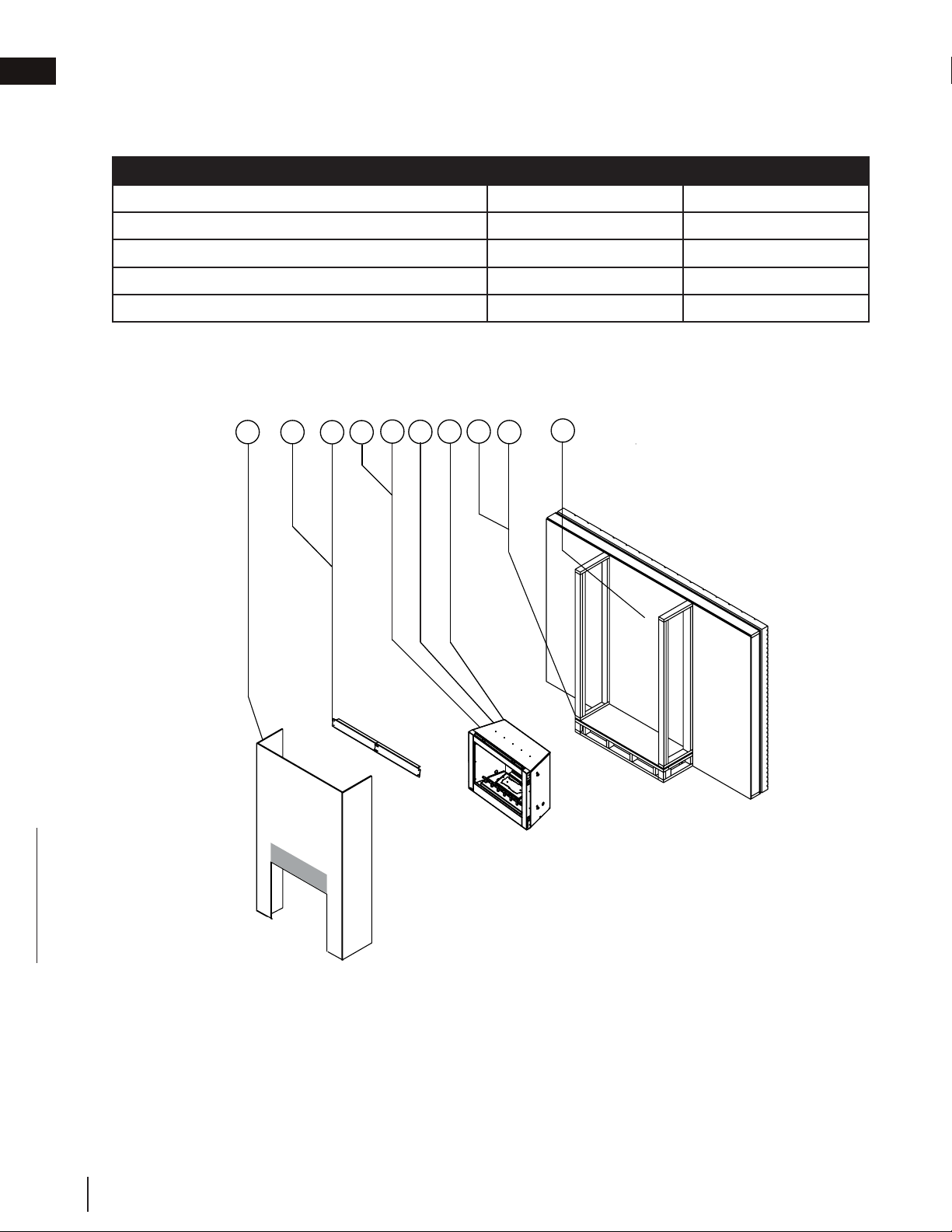
1.3 installation overview
For your satisfaction, this appliance has been test-fired to assure its operation and quality.
1. Determine the final location of the appliance (see “location” section).
2. Determine the most appropriate gas inlet location (see “gas inlet location” section).
3. Plan out appliance enclosure, framing, fronts, accessories, etc.
4. Install rough framing (see “framing” section).
5. Install optional remote if necessary.
6. Install gas lines (see “gas installation” section).
7. Test appliance.
8. Install nailing tabs (see “nailing tab installation” section).
9. Complete framing (see “framing” section).
10. Complete finishing (see “finishing” section).
10
4
6
7
3
2
1
5
8
9
W415-1796 / A / 05.17.18
EN
6
general information
When the appliance is installed directly on combustible material other than wood flooring, the appliance shall be
installed on a metal or wood panel extending the full width and depth.
Solid fuels shall not be burned in this appliance.
!
WARNING
• Never obstruct the front opening of the appliance.
• Objects placed in front of the appliance must be kept a minimum of 48” (121.9cm) from the front face of
the appliance.
• Fire risk. Explosion hazard.
• High pressure will damage valve. Disconnect gas supply piping before pressure testing gas line at test
pressures above 1/2 PSIG. Close the manual shut-off valve before pressure testing gas line at pressures
equal to or less than 1/2PSIG (35mb).
• Use only Wolf Steel approved optional accessories and replacement parts with this appliance. Using non-
listed accessories (blowers, doors, louvres, trims, gas components, venting components, etc.) could result
in a safety hazard and will void the warranty and certification.
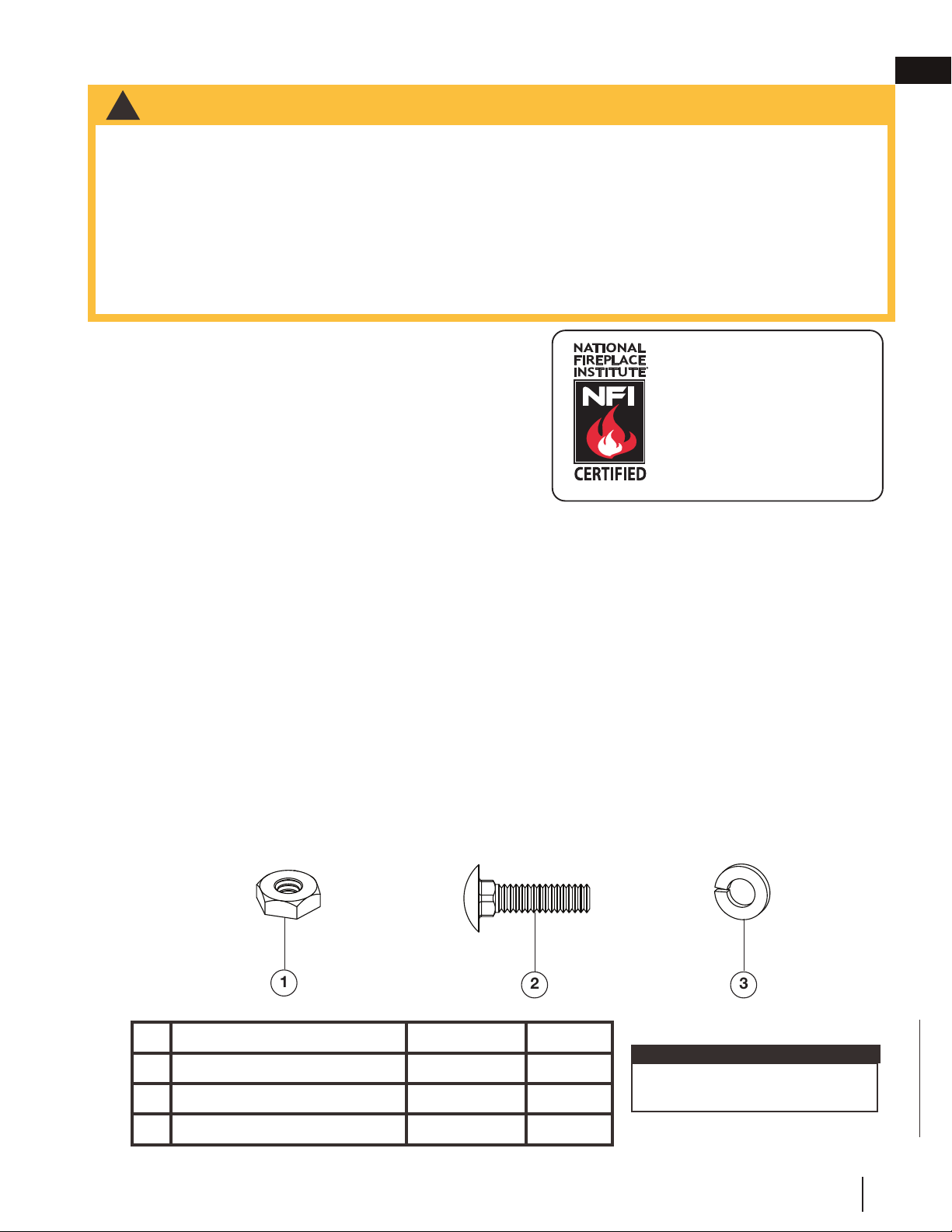
1.4 hardware list
note:
DESCRIPTION PART NUMBER QUANTITY
1
Nut, Hex #10-24 W450-0014 3
2
Bolt, #10-24 Carriage W065-0027 3
3
Washer, 1/4 Lock W735-0001 3
Only fasteners supplied with the
appliance are illustrated.
4.3
THIS GAS APPLIANCE SHOULD BE INSTALLED AND
SERVICED BY A QUALIFIED INSTALLER to conform with
local codes. Installation practices vary from region to region
and it is important to know the specifi cs that apply to your
area, for example in Massachusetts State:
• The appliance off valve must be a “T” handle gas cock.
• The fl exible connector must not be longer than 36”
(91.4cm).
The installation must conform with local codes or, in absence
of local codes, the National Gas and Propane Installation Code CSA B149.1 in Canada, or the National Fuel Gas
Code, ANSI Z223.1 / NFPA 54 in the United States.
The appliance and its individual shutoff valve must be disconnected from the gas supply piping system during
any pressure testing of that system at test pressures in excess of 1/2 psig (35 mb). The appliance must be
isolated from the gas supply piping system by closing its individual manual shutoff valve during any pressure
testing of the gas supply piping system at test pressures equal to or less than 1/2 psig (35 mb). When installed
with a blower or fan, the junction box must be electrically connected and grounded in accordance with local
codes. In the absence of local codes, use the current CSA C22.1 Canadian Electrical Code in Canada or the
ANSI / NFPA 70 National Electric Code in the United States. In the case where the blower is equipped with
a power cord it must be connected into a properly grounded receptacle. The grounding prong must not be
removed from the cord plug.
We suggest that our gas
hearth products be installed
and serviced by professionals
who are certied in the U.S.
by the National Fireplace
Institute
®
(NFI) as NFI Gas
Specialists
www.ncertied.org
1
2
3
EN
W415-1796 / A / 05.17.18
7
general information
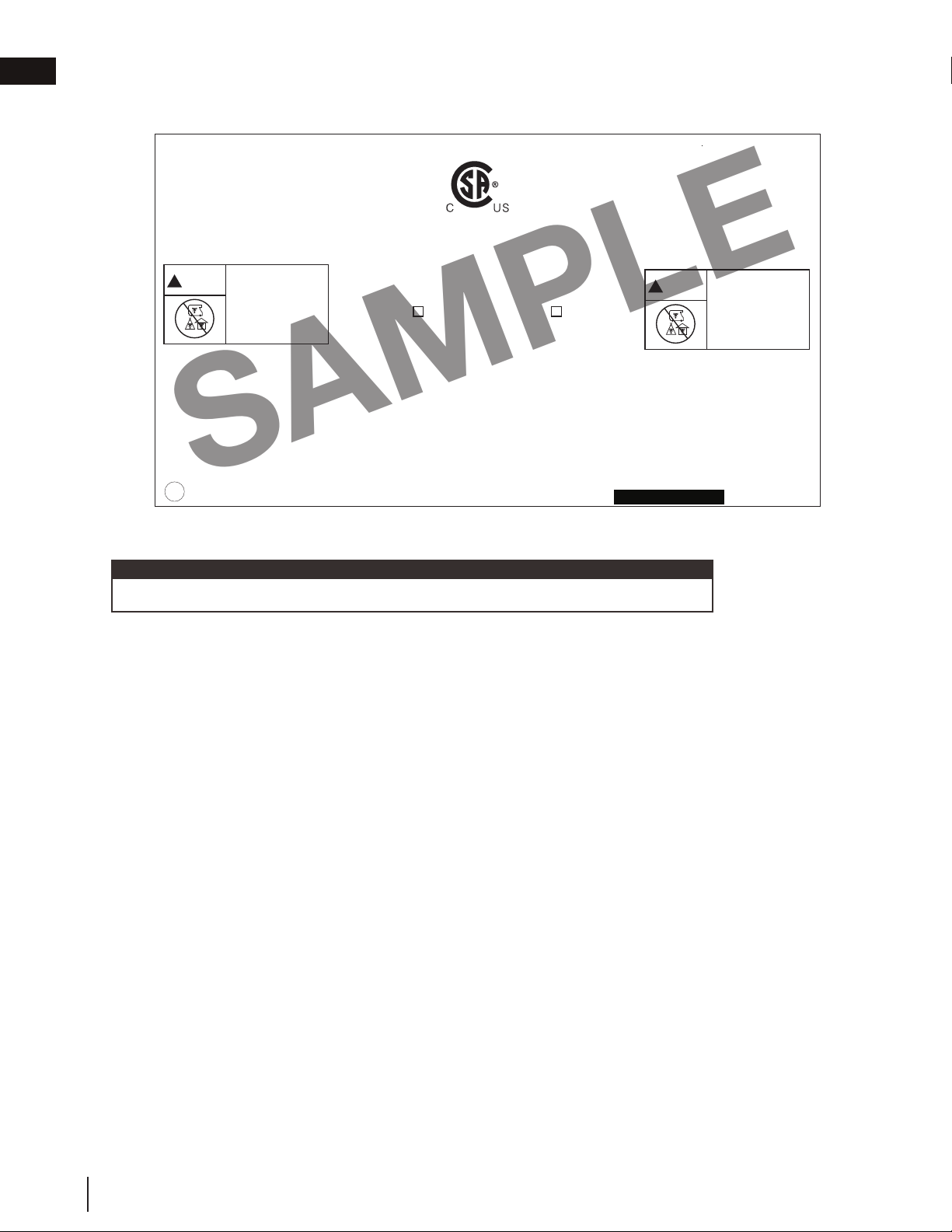
1.5 rating plate information
This illustration is for reference only. Refer to the rating plate on the appliance for accurate information.
The rating plate must remain with the appliance at all times. It must not be removed.
note:
TITLE: GSS36 RATING PLATE: OPERATING & LIGHTING INSTRUCTIONS
REVISION:
DWG#: W385-2296
DATE: 03.19.18_T.B.
Page 1 of 2
GSS36
W385-2296
CERTIFIED UNDER / HOMOLOGUÉ SELON LES NORMES: ANSI Z21.97-2014 - CSA 2.41-2014. OUTDOOR GAS FIREPLACE / FOYER AU GAZ EXTÉRIEUR
WOLF STEEL LTD.
24 NAPOLEON ROAD, BARRIE, ON, L4M 0G8 CANADA
CAUTION : THE GAS PRESSURE REGULATOR PROVIDED WITH THIS APPLIANCE MUST BE USED.
THIS REGULATOR IS SET FOR AN OUTLET PRESSURE OF 3.5 INCHES WATER COLUMN FOR
NG AND 10 INCHES WATER COLUMN FOR P. THE GAS SUPPLY MUST BE TURNED OFF AT
THE P-GAS SUPPLY CYLINDER WHEN THIS APPLIANCE IS NOT IN USE. DO NOT STORE OR
USE GASOLINE OR OTHER FLAMMABLE VAPOURS AND LIQUIDS IN THE VICINITY OF THIS
OR ANY OTHER APPLIANCE. AN P-CYLINDER NOT CONNECTED FOR USE SHALL NOT BE
STORED IN THE VICINITY OF THIS OR ANY OTHER APPLIANCE. DO NOT CONNECT TO A
REMOTE GAS SUPPLY IMPROPER INSTALLATION, ADJUSTMENT, ALTERATION, SERVICE OR
MAINTENANCE CAN CAUSE INJURY OR PROPERTY DAMAGE. READ THE INSTALLATION,
OPERATING AND MAINTENANCE INSTRUCTIONS THOROUGHLY BEFORE INSTALLING OR
SERVICING THIS EQUIPMENT.REFER TO THE OWNER’S MANUAL PROVIDED WITH THIS APPLIANCE.
FOR ASSISTANCE OR ADDITIONAL INFORMATION, CONSULT A QUALIFIED INSTALLER, SERVICE
AGENCY OR GAS SUPPLIER. MUST NOT BE USED FOR COOKING. FOR OUTDOOR USE ONLY. IF
STORED INDOORS, DETACH AND LEAVE CYLINDER OUTDOORS.
ATTENTION : LE RÉGULATEUR DE PRESSION DE GAZ FOURNI AVEC CET APPAREIL DOIT ÊTRE UTILISÉ.
CE RÉGULATEUR EST RÉGLÉ POUR UNE PRESSION DE SORTIE DE 3,5 POUCES D’UNE
COLONNE D’EAU POUR NG ET 10 POUCES D’UNE COLONNE D’EAU POUR P. LORSQUE CET
APPAREIL N’EST PAS UTILISÉ, VOUS DEVEZ FERMER L’ALIMENTATION EN GAZ SUR LA
BONBONNE DE PROPANE. N’ENTREPOSEZ PAS ET N’UTILISEZ PAS D’ESSENCE OU AUTRES
LIQUIDES ET VAPEURS INFLAMMABLES À PROXIMITÉ DE CET APPAREIL OU TOUT AUTRE
APPAREIL. UNE BOUTEILLE DE PROPANE QUI N’EST PAS RACCORDÉE EN VUE DE SON
UTILISATION, NE DOIT PAS ÊTRE ENTREPOSÉE DANS LE VOISINAGE DE CET APPAREIL OU DE
TOUT AUTRE APPAREIL. NE CONNECTEZ PAS À UNE FOURNITURE DE GAZ À DISTANCE. UNE
INSTALLATION NON CONFORME, DES AJUSTEMENTS, DES ALTÉRATIONS, UN SERVICE OU UN
ENTRETIEN INADÉQUATS PEUVENT CAUSER DES DOMMAGES À LA PROPRIÉTÉ OU DES
BLESSURES CORPORELLES. VEUILLEZ LIRE ATTENTIVEMENT LES INSTRUCTIONS D’INSTALLATION,
D’UTILISATION ET D’ENTRETIEN AVANT D’INSTALLER OU DE RÉPARER CE MATÉRIEL. RÉFÉREZ-VOUS AU
MANUEL DU PROPRIÉTAIRE FOURNI AVEC CET APPAREIL. POUR DE L’ASSISTANCE OU POUR PLUS
D’INFORMATION, CONSULTEZ UN INSTALLATEUR QUALIFIÉ, UNE AGENCE D’ENTRETIEN OU LE
FOURNISSEUR DE GAZ. NE PAS UTILISER POUR LA CUISSON. POUR USAGE EXTÉTIEUR SEULEMENT. SI
ENTREPOSÉ À L’INTÉRIEUR, DÉTACHER LA
BONBONNE DE PROPANE ET LA LAISSER À
L’EXTÉRIEUR.
GSS36CFN MODEL GSS36CFP
0-4500FT (0-1370m) ALTITUDE / ÉLÉVATION 0-4500FT (0-1370m)
40,000 BTU/h INPUT / ALIMENTATION 40,000 BTU/h
29,000 BTU/h REDUCED INPUT / ALIMENTATION RÉDUITE 32,000 BTU/h
MANIFOLD PRESSURE: 3.5" WATER COLUMN MANIFOLD PRESSURE: 10" WATER COLUMN
PRESSION AU COLLECTEUR: 3.5" D'UNE COLONNE D'EAU PRESSION AU COLLECTEUR: 10" D'UNE COLONNE D'EAU
MINIMUM SUPPLY PRESSURE: 4.5" WATER COLUMN MINIMUM SUPPLY PRESSURE: 11" WATER COLUMN
PRESSION D'ALIMENTATION MINIMALE: 4.5" D'UNE COLONNE D'EAU PRESSION D'ALIMENTATION MINIMALE: 11" D'UNE COLONNE D'EAU
MAXIMUM SUPPLY PRESSURE: 7.0" WATER COLUMN MAXIMUM SUPPLY PRESSURE: 13" WATER COLUMN
PRESSION D'ALIMENTATION MAXIMALE: 7.0" D'UNE COLONNE D'EAU PRESSION D'ALIMENTATION MAXIMALE: 13" D'UNE COLONNE D'EAU
NOT FOR USE WITH SOLID FUEL.
WARNING: THIS APPLIANCE USES AND REQUIRES A FAST ACTING THERMOCOUPLE.
REPLACE ONLY WITH A FAST ACTING THERMOCOUPLE SUPPLIED BY WOLF STEEL LTD.
DO NOT ADD ANY MATERIAL TO THE APPLIANCE, WHICH WILL COME IN CONTACT WITH THE
FLAMES, OTHER THAN THAT SUPPLIED BY THE MANUFACTURER WITH THE APPLIANCE.
MINIMUM CLEARANCE TO COMBUSTIBLE MATERIALS:
TOP 14 1/2” BACK 1”
FLOOR 0“ MANTEL 14 1/2”
SIDES 1” RECESSED DEPTH 20 1/2”
SEE INSTALLATION INSTRUCTIONS FOR FRAMING CLEARANCES.
UN COMBUSTIBLE SOLIDE NE DOIT PAS ÊTRE UTILISÉ
AVEC CET APPAREIL.
AVERTISSEMENT: CET APPAREIL UTILISE ET REQUIERT UN THERMOCOUPLE À ACTION
RAPIDE. REPLACEZ UNIQUEMENT AVEC UN THERMOCOUPLE À ACTION RAPIDE DE WOLF STEEL
LTÉE. N'AJOUTEZ PAS A CET APPAREIL AUCUN MATÉRIAUX DEVANT ENTRER EN CONTACT AVEC
LES FLAMMES AUTRE QUE CELUI QUI EST FOURNI AVEC CET APPAREIL PAR LE FABRICANT.
DÉGAGEMENTS MINIMAUX DES MATÉRIAUX COMBUSTIBLES:
DESSUS 14 1/2” ARRIÈRE 1”
PLANCHER 0“ MANTEAU 14 1/2”
CÔTÉS 1” PROFONDEUR DE L’ENCAVE 20 1/2”
POUR LES DÉGAGEMENTS AUX MATÉRIAUX D’OSSATURE, VOIR LE MANUEL D’INSTRUCTIONS.
SERIAL NUMBER/NO. DE SÉRIE:
MATERIAL: CLASS IIIA-2 PERMANENT LABEL, .010 VELT MATTE LEXAN AND/OR .050 HI-TEMP POLYESTER, WATERPROOF, NON-WATER SOLUBLE ADHESIVE CAPABLE OF
WITHSTANDING 79⁰C (175⁰F) TEMPERATURES. DIAMETER HOLE WITH 0.250” MATERIAL ON RIGHT AND BOTTOM.
MIN. LETTERING FOR "NOT FOR USE WITH SOLID FUEL. ", "UN COMBUSTIBLE SOLIDE NE DOIT PAS ÊTRE UTILISÉ AVEC CELUI." TO BE 10 POINT ARIAL, BOLD FACE, UPPER
CASE AND 2 POINT LEADING SPACING OR EQUIVALENT.
BLACK ON WHITE BACKGROUND
MAX OVERALL DECAL SIZE: 8.5" x 4.75”
SERIAL NUMBERS TO BE ASCENDING FROM GSS36014418
REF. NO. 161746
NO. DE RÉF. 161746
CARBON MONOXIDE HAZARD
This appliance can produce carbon
monoxide which has no odour.
Using it in an enclosed space can kill you.
Never use this appliance in an enclosed
space such as a camper, tent, car or
home.
DANGER
!
MONOXYDE DE CARBONE
Cet appareil peut produire du monoxyde
de carbone, un gaz inodore.
L’utilisation de cet appareil dans des
espaces clos peut entraîner la mort.
Ne jamais utiliser cet appareil dans un
espace clos comme un véhicle de
camping, une tente, une automobile, ou
une maison.
DANGER
!
SAMPLE
W415-1796 / A / 05.17.18
EN
8
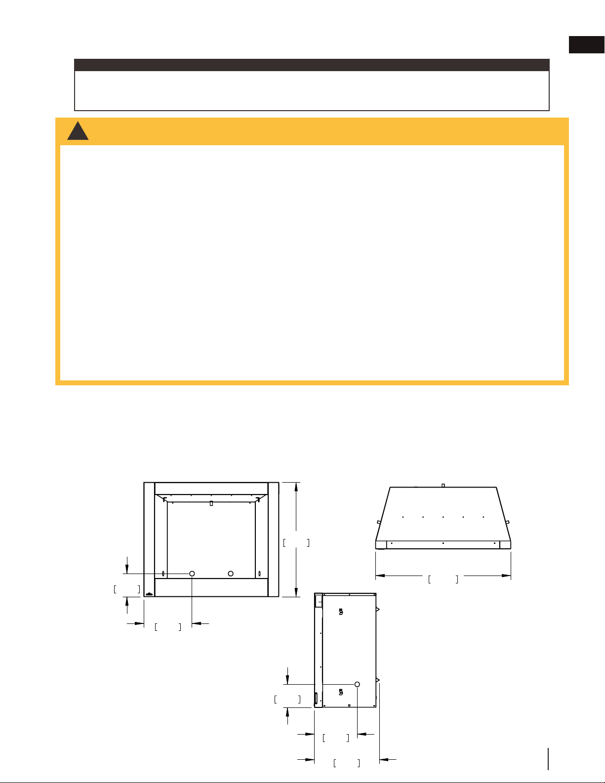
general information
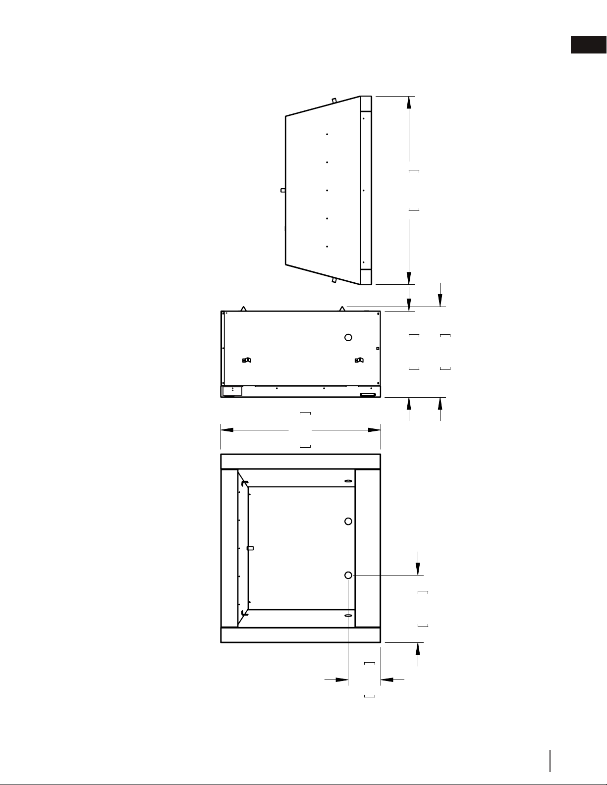
2.0 dimensions
35 9/16"
904mm
15"
381mm
7 3/16"
183mm
20 3/16"
513mm
19 3/16"
487mm
42"
1066mm
FRONT VIEW RIGHT SIDE VIEW TOP VIEW
front view right side view top view
EN
W415-1796 / A / 05.17.18
9
3.0 location
It is important when selecting a location for your appliance to ensure clearances to adjacent combustibles are
met. This appliance is intended for installation on an outdoor patio or in your yard. It is highly recommended that
this appliance be installed in a sheltered area (following the guidelines outlined below). Direct wind will cause an
erratic flame and possible pilot or main burner outage. An erratic flame could also lead to excessive carboning
(black soot), which is not a safety issue but is visually undesirable.
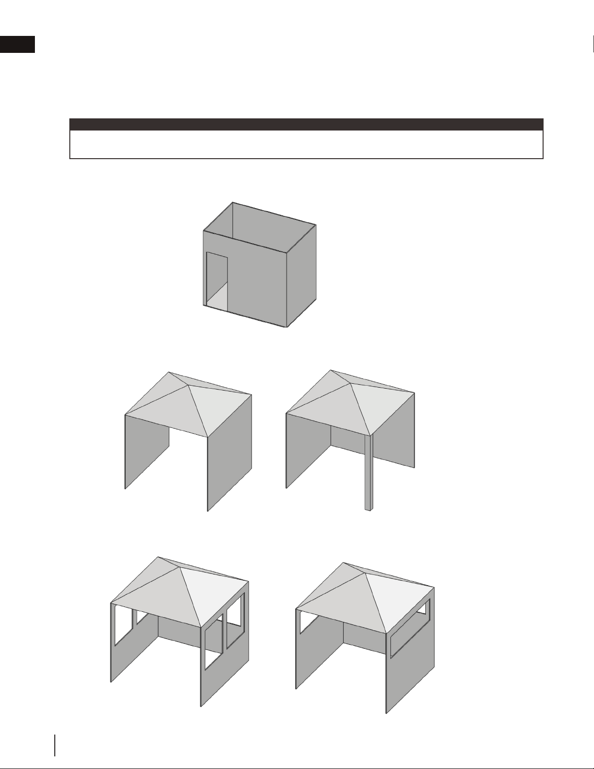
Any enclosure (shelter) in which the appliance is used must comply with one of the following:
With walls on all sides, but at least one permanent opening at ground level and no overhead cover (FIG. 1).
Within a partial enclosure which includes an overhead cover and no more than two sidewalls. These sidewalls may
be parallel, as in a breezeway, or at right angles to each other (FIG. 2).
Within a partial enclosure which includes an overhead cover and three widewalls, as long as 30 percent or more
of the horizontal periphery of the enclosure is permanently open (FIG.3).
When choosing a location for your appliance, care must be taken to avoid areas where excessive moisture or
running water may be a problem.
note:
FIG. 1
FIG. 2
FIG. 3
W415-1796 / A / 05.17.18
EN
10
!
WARNING
• Risk of fi re!
• In order to avoid the possibility of exposed insulation or vapour barrier coming in contact with the appliance
body, it is recommended that the walls of the appliance enclosure be “fi nished” (i.e. drywall / sheetrock),
as you would fi nish any other outside wall of a home. This will ensure that clearance to combustibles is
maintained within the cavity.
• Do not notch the framing around the appliance stand offs. Failure to maintain air space clearance may cause
over heating and fi re. Prevent contact with sagging or loose insulation or framing and other combustible
materials. Block opening into the chase to prevent entry of blown-in insulation. Make sure insulation and
other materials are secured.
• When constructing the enclosure, allow for fi nishing material thickness to maintain clearances. Framing or
fi nishing material closer than the minimums listed must be constructed entirely of non-combustible materials.
Materials consisting entirely of steel, iron, brick, tile, concrete, slate, glass or plasters, or any combination
thereof are suitable. Materials that are reported as passing ASTM E136, standard test method for behaviour
of materials in a vertical tube furnace at 1382ºF (750ºC) and UL763 shall be considered non-combustible
materials.
• Minimum clearance to combusibles must be maintained or a serious fi re hazard could result.
• The appliance requires a minimum enclosure height. Measure from the appliance base.
• If steel stud framing kits with cement board are provided, or specifi ed in the installation instructions, they
must be installed.
• If specifi ed in the installation instruction, fi nishing must be done using a non-combustible board, ceramic tile,
marble, etc. Do NOT use wood or drywall. Any fi re rated drywall is not acceptable.
When using optional fi nishing accessories, the framing dimensions and fi nishing materials may differ from
what is outlined in the section below; refer to the leafl et instructions supplied in the accessory kit for specifi c
framing and fi nishing specifi cations.
44.1
note:
4.0 framing
It is recommended that the walls of the appliance enclosure be finished. This would ensure that clearance to
combustibles is maintained within the cavity. It is best to frame your appliance after it is positioned. Use 2x4’s and
frame to local building codes.
4.1 gas inlet locations
There are five gas inlet locations on the ventless firebox enclosure: one on each side of the appliance, two at
the rear, and one on the bottom. Use the following illustrations to identify the preferred inlet and then remove the
corresponding knock out.
35 9/16"
904mm
7 3/16"
183mm
15"
381mm
20 3/16"
513mm
13 5/16"
338mm
7 3/16"
183mm
42"
1066mm
21 1/16"
534mm
15 5/8"
397mm
BOTTOM VIEW
FRONT VIEW RIGHT SIDE VIEW TOP VIEW
35 9/16"
904mm
7 3/16"
183mm
15"
381mm
20 3/16"
513mm
13 5/16"
338mm
7 3/16"
183mm
42"
1066mm
21 1/16"
534mm
15 5/8"
397mm
BOTTOM VIEW
FRONT VIEW RIGHT SIDE VIEW TOP VIEW
35 9/16"
904mm
7 3/16"
183mm
15"
381mm
20 3/16"
513mm
13 5/16"
338mm
7 3/16"
183mm
42"
1066mm
21 1/16"
534mm
15 5/8"
397mm
BOTTOM VIEW
FRONT VIEW RIGHT SIDE VIEW TOP VIEW
EN
W415-1796 / A / 05.17.18
11

Do not put objects in front of the appli-
ance (minimum distance of 4 feet)
44”
(111.7cm)
21”
(53.3cm)
44”
(111.7cm)
4.2 minimum framing dimensions
Minimum clearance to combustibles construction from appliance and vent surfaces:
Framing 0” (0mm) to stand-offs (rear and sides only)
Use a combustible header for the top and two side combustible studs
Finishing 1” (25mm) to back and sides
Non-combustible finishing 14 1/2” (36.8cm) from the top of the appliance
Recessed depth 20 1/2” (52cm)
Enclosure top 50 3/4” (128.9cm) from bottom of appliance
Clearance to ceiling 72” (182.8cm) from bottom of appliance.
6” (152.4mm) MIN.
(If installing optional doors,
18” (45.7cm))
53”
(134.6cm)
16”
(40.6cm)
74 1/2”
(189.2cm)
W415-1796 / A / 05.17.18
EN
12
framing
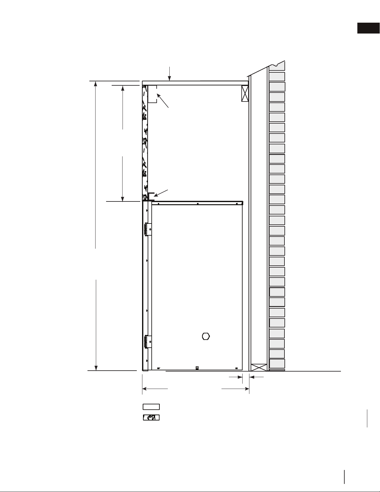
1” (25.4cm)
Top of combustible enclosure
50 3/4”
(128.9cm)
14 1/2”
(36.8cm)
Non-combustible
header (provided)
Non-Combustible Material
Top of
appliance
Combustible Material
Nailing strip
20 1/2” (52cm)
4.3 minimum enclosure clearances
This appliance requires a minimum enclosure height of 50 3/4” (128.9cm).
For temperature requirements, the enclosure space around and above the appliance must be left unobstructed.
EN
W415-1796 / A / 05.17.18
13
framing
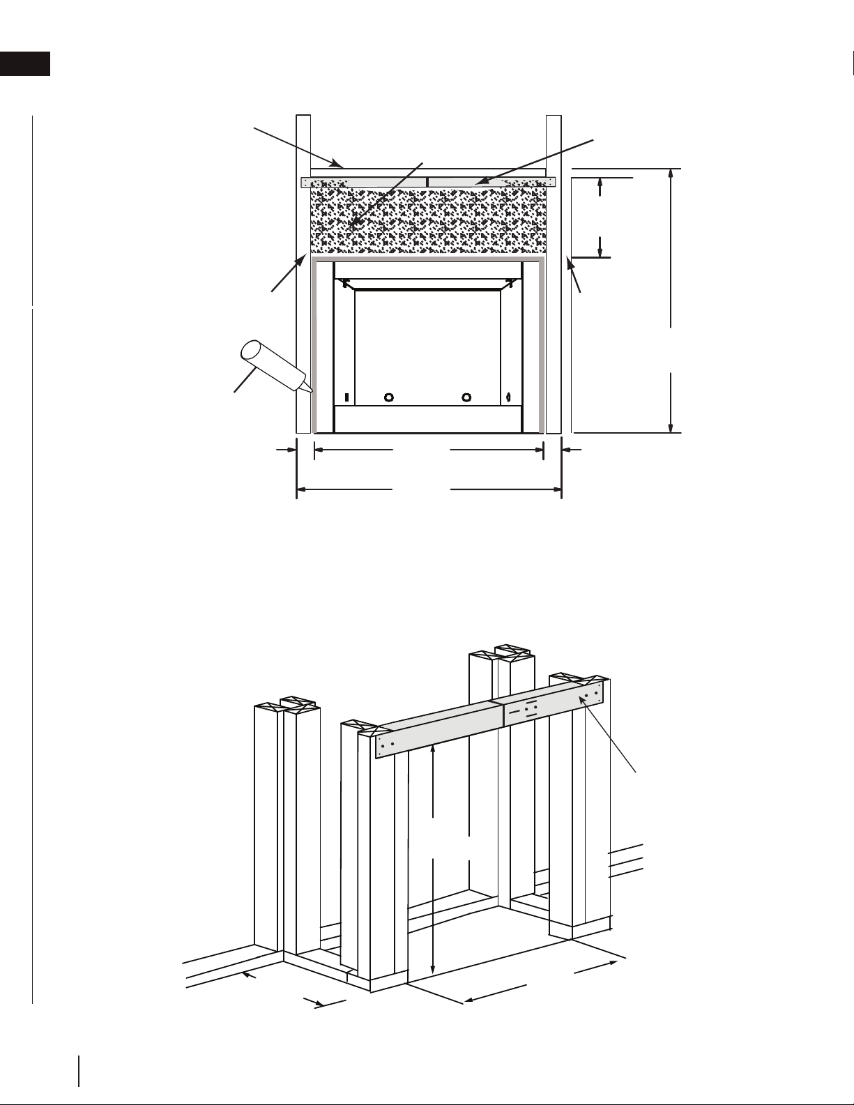
46 9/16"
(118.2cm)
36"
(91,4cm)
44”
(111.7cm)
20 1/2”
(52cm)
21”
(53,3cm)
42”
(106,7cm)
Steel Header
(Supplied)
4.4 minimum clearance to combustible enclosures
48
"
(121.9cm)
2"
(5mm)
2"
(5mm)
44
"
(111.7cm)
50
3
/
4"
(128.9cm)
14 1/2” *
(36.8cm)
Non-combustible
finishing material
Steel header
(provided)
Combustible
stud
Combustible
stud
Top of
Combustible
Enclosure
Outdoor
Sealant**
*From Top of Appliance
* From top of appliance.
** An outdoor sealant must be used along the edge of the appliance and the non-combustible material to keep water
from entering the chase.
W415-1796 / A / 05.17.18
EN
14
framing
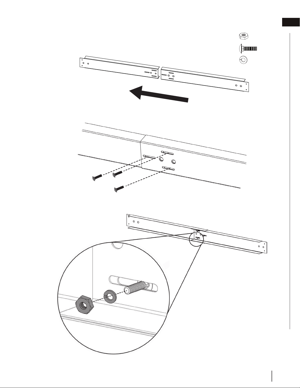
Type 1 (x3)
Type 2 (x3)
Type 3 (x3)
4.5 steel header installation
1. Slide the 2 steel header pieces together, ensuring to align the 3 slots (FIG. 1).
2. Insert the 3 supplied bolts (Type 2) through the 3 slots (FIG. 2).
3. Secure the 3 nuts (Type 1) and the 3 washers (Type 3) to the back of the bolts (FIG. 3).
FIG. 1
FIG. 2
FIG. 3
Reverse Side View
EN
W415-1796 / A / 05.17.18
15
framing
5.0 electrical information
5.1 optional wall switch installation
34.1
!
WARNING
• Do not connect either the wall switch, thermostat or gas valve directly to 110 volt electricity.
For ease of accessibility, an optional remote wall switch or millivolt thermostat may be installed in a convenient
location. Route a 2 strand, solid core millivolt wire from the valve to the wall switch or millivolt thermostat. The
recommended maximum lead length depends on wire size:
WIRE SIZE MAX. LENGTH
14 gauge (1.8mm) 100 feet (30.5m)
16 gauge (1.5mm) 60 feet (18.3m)
18 gauge (1.2mm) 40 feet (12.2m)
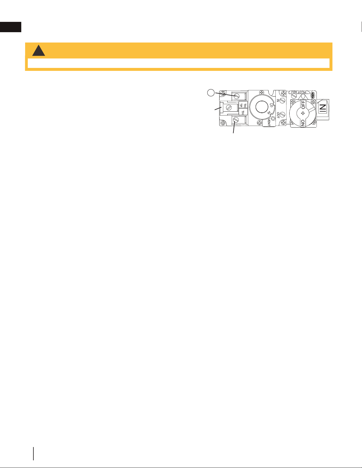
Disconnect the existing wires from terminals 1 and 3 (from the
ON/OFF switch) and replace with the leads from the wall switch / millivolt thermostat.
ADD IMAGE
HERE
P
I
L
O
T
TP
3
W415-1796 / A / 05.17.18
EN
16

6.0 gas installation
!
WARNING
• Risk of fire, explosion, or asphyxiation. Ensure there are no ignition sources such as sparks or open flames.
• Support gas control when attaching gas supply pipe to prevent damaging gas line.
• Purging of the gas supply line should be performed by a qualified service technician. Ensure that a continuous
gas flow is at the burner before closing the door. Ensure adequate ventilation. For gas and electrical locations,
see “appliance dimensions” section.
• All gas connections must be contained within the appliance when complete.
• High pressure will damage valve. Disconnect gas supply piping before testing gas line at test pressures above
1/2 PSIG.
• Valve settings have been factory set, do not change.
Installation and servicing to be done by a qualified installer.
• Move the appliance into position and secure.
• If equipped with a flex connector, the appliance is designed to accept a 1/2” (13mm) gas supply. Without the
connector, it is designed to accept a 3/8” (9.5mm) gas supply. The appliance is equipped with a manual shut
off valve to turn off the gas supply to the appliance.
• Connect the gas supply in accordance to local codes. In the absence of local codes, install to the current
CAN/CSA-B149.1 Installation Code in Canada or to the current National Fuel Gas Code, ANSI Z223.1 / NFPA
54 in the United States.
• When flexing any gas line, support the gas valve so that the lines are not bent or kinked.
• The gas line flex-connector should be installed to provide sufficient movement for shifting the burner assembly
on its side to aid with servicing components.
• Check for gas leaks by brushing on a soap and water solution. Do not use open flame.
EN
W415-1796 / A / 05.17.18
17
7.0 operation
31.1A
!
WARNING
• Do not turn on if children or other at risk individuals are near the appliance.
• This appliance is equipped with a pilot which must be lit by hand while following these instructions exactly.
• Before operating, smell all around the appliance area for gas and next to the fl oor because some gas is heavier
than air and will settle on the fl oor.
• Use only your hand to turn the gas control knob. Never use tools. If the knob will not turn by hand, do not try
to repair it. Call a qualifi ed service technician. Force or attempted repair may result in a fi re or explosion.
• Do not use this appliance if any part has been under water. Immediately call a qualifi ed service technician
to inspect the appliance and replace any part of the control system and any gas control which has been
underwater.
FOR YOUR SAFETY READ BEFORE LIGHTING
WHAT TO DO IF YOU SMELL GAS
LIGHTING INSTRUCTIONS
TO TURN OFF GAS
A. Stop! Read the above safety information on this label.
B. Remove batteries from the transmitter and set thermostat to lowest setting, if equipped.
C. Turn off all electrical power to the appliance.
D. Open the glass door, if equipped.
E. Turn the gas knob clockwise to the “OFF” position.
F. Wait fi ve (5) minutes to clear out any gas. If you smell gas including near the fl oor, STOP!
Follow the instructions above in the “WHAT TO DO IF YOU SMELL GAS” section. If you
don’t smell gas; close the glass door and go to the next step.
G. If the appliance is equipped with fl ame adjustment valve turn clockwise to “OFF”.
H. Turn gas knob counter-clockwise to the “PILOT” position. (If the appliance is equipped
with an “ON/OFF” switch, ensure it is in the “ON” position.
I. Depress and hold gas knob while lighting the pilot with the push button ignitor. Keep knob
fully depressed for one minute, then release. If pilot does not continue to burn, repeat steps
E through I.
J. With pilot lit, turn gas knob counter-clockwise
to the “ON” position.
K. If equipped with the fl ame adjustment valve, push and turn the knob to high.
L. Turn on all electrical power to the appliance and re-install the batteries into the transmitter, if
equipped. Set thermostat to desired setting, if equipped.
A. Set thermostat to desired setting, if equipped.
B. Turn off all electrical power to the appliance if service is to be performed.
C. Push in gas knob slightly and turn clockwise to the “OFF” position. Do not force.
• Turn off all gas to the appliance.
• Open windows.
• Do not try to light any appliance.
• Do not touch any electric switch; do not use
any phone in your building
• Immediately call your gas supplier from a
neighbour’s phone. Follow the gas supplier’s
instructions.
• If you cannot reach your gas supplier, call
the fi re department.
• If you do not follow these instructions exactly, a fi re or explosion may result causing property damage, personal
injury, or loss of life.
• If applicable, always light the pilot whether for the fi rst time or if the gas supply has run out with the glass door
opened or removed.
add gas knob
add gas valve
Ensure that a continuous gas fl ow is at the burner before installing the door. When lit for the fi rst time, the appliance
will emit an odor for a few hours. This is a normal temporary condition caused by the “burn-in” of paints and
lubricants used in the manufacturing process and will not occur again. After extended periods of non-operation
such as following a vacation or a warm weather season, the appliance may emit a slight odor for a few hours. This
is caused by dust particles in the heat exchanger burning off. In both cases, open a window to suffi ciently ventilate
the room.
For vent free appliances ONLY: if the appliance shuts off, do not relight until you provide fresh air. If appliance
keeps shutting off, have it serviced. Keep burner and control compartment clean.
note:
When lighting and re-lighting, the gas knob cannot be turned from pilot to off unless the knob is
depressed.
W415-1796 / A / 05.17.18
EN
18
Reverse Side
View
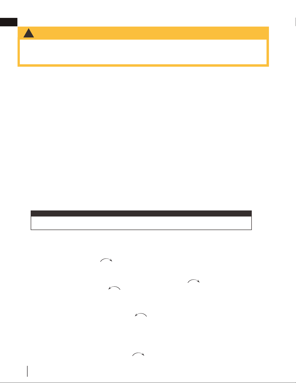
1. To install the appliance face flush with the finished surface, position the framework to accommodate the
thickness of the finished surface.
2. Remove the 4 screws (FIG. 1).
3. Install the 4 nailing brackets on both sides of the appliance, and secure to the 2x4 framing.
8.0 nailing tabs and strips
8.1 nailing tab installation (located in manual baggie)
8.2 nailing strip installation
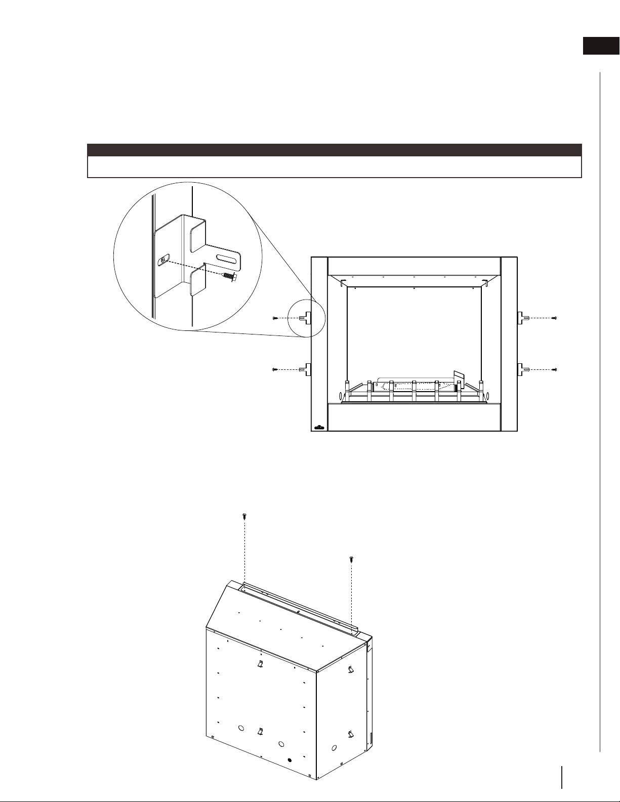
1. Remove the nailing strip from the back side of the carton sleeve.
2. Remove the 2 screws from the outer top edges of the nailing strip.
3. Place the nailing strip in place and secure with the 2 previously removed screws (FIG. 1).
The tabs will facilitate the installation of either a 1/2” (12.7mm) or 3/4” (19.1mm) finished surface thickness.
note:
FIG. 1
FIG. 1
Back Side View
EN
W415-1796 / A / 05.17.18
19
9.0 finishing
!
WARNING
• Failure to position the logs in accordance with these diagrams or failure to use only logs specifically approved
with this appliance may result in property damage or personal injury.
• Logs must be placed in their exact location in the appliance. Do not modify the proper log positions, since
appliance may not function properly and delayed ignition may occur.
• The logs are fragile and should be handled with care.
PHAZER™ logs and glowing embers, exclusive to Napoleon, provide a unique and realistic glowing effect that
is different in every installation. Take the time to carefully position the glowing embers for a maximum glowing ef-
fect. Log colours may vary. During the initial use of the appliance, the colours will become more uniform as colour
pigments burn in during the heat-activated curing process. Blocked burner ports can cause an incorrect flame
pattern.
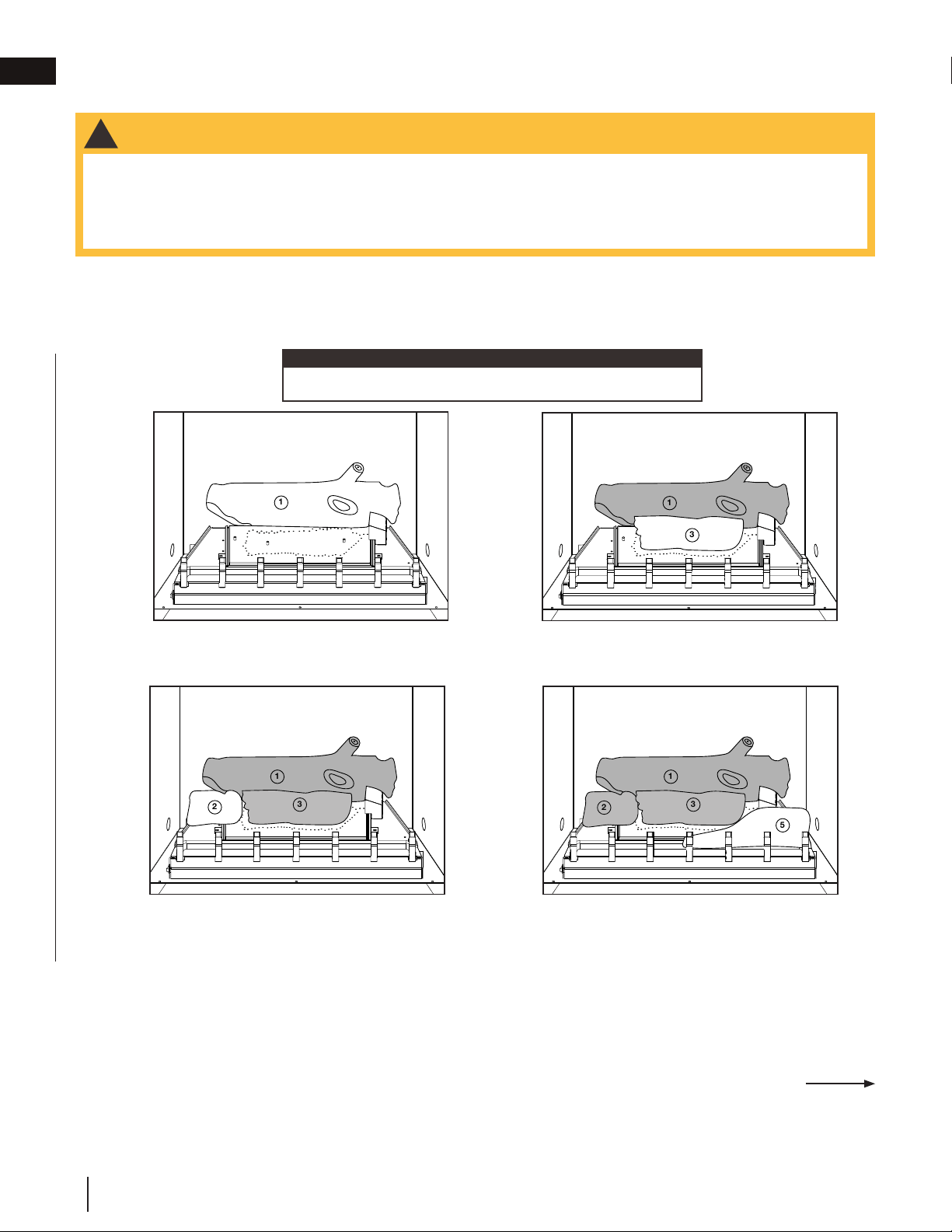
9.1 birch wood log placement (BLKO36)
1. Place log #1 on the rear bracket, ensuring the
notch on the right side of the log fits around
the pilot shield. Do not cover any burner ports.
2. Place the two holes in log #3 on the two studs
located in the center of the burner. Do not
cover any burner ports.
3. Place the hole in log #2 on the stud located on
the left side of the burner.
4. Place log #5 along the front right side of the
grate and then pull it forward, ensuring the log
notches align with the grate posts.
1
1
3
1
3
2
1
3
2
5
Continued on next page
Log numbers are located on the bottom or back of the logs.
note:
W415-1796 / A / 05.17.18
EN
20
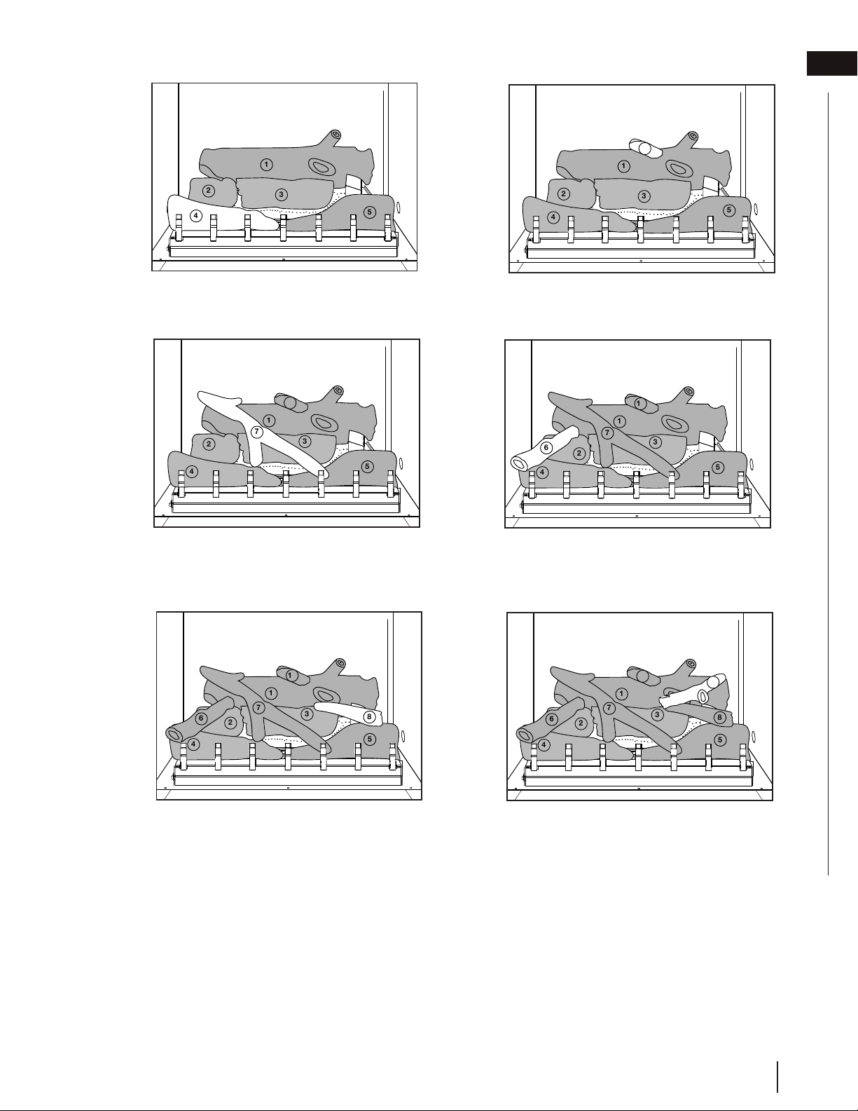
7. Place log #7 crosswise, ensuring the top rests
on the top left notch of log #1 and the bottom
rests on the top left notch of log #5.
8. Place log #6 crosswise, ensuring the top rests
on the top center notch of log #2 and the
bottom rests on the top left notch of log #4.
Log #6 should touch the front face of log #1.
9. Place log #8 crosswise, ensuring the top rests
on the top right notch of log #3 and the bot-
tom rests on the top center notch of log #5.
The thin end of log #8 should face inwards.
10. Place log #9 crosswise, ensuring the top rests
on the top right notch of log #1 and the bottom
rests on the top left notch of log #8.
1
3
2
5
4
7
10
1
3
2
10
5
4
7
6
1
3
2
10
5
4
6
7
8
1
3
2
5
4
6
7
8
9
10
5. Place log #4 along the front left side of the
grate and then pull it forward, ensuring the log
notches align with the grate posts.
6. Place log #10 on the top notch of log #1.
1
3
2
4
5
1
3
2
4
5
10
EN
W415-1796 / A / 05.17.18
21
finishing
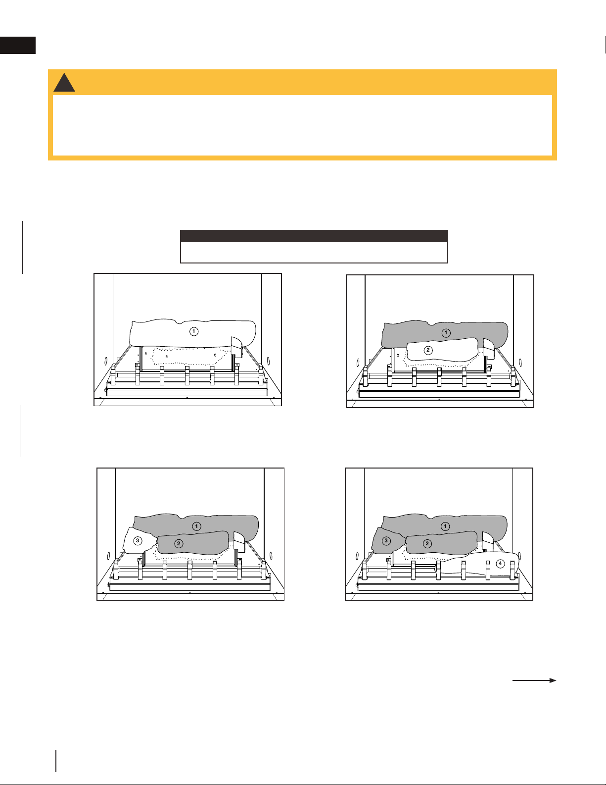
9.2 oak wood log placement (OLKO36)
!
WARNING
• Failure to position the logs in accordance with these diagrams or failure to use only logs specifically approved
with this appliance may result in property damage or personal injury.
• Logs must be placed in their exact location in the appliance. Do not modify the proper log positions, since
appliance may not function properly and delayed ignition may occur.
• The logs are fragile and should be handled with care.
PHAZER™ logs and glowing embers, exclusive to Napoleon, provide a unique and realistic glowing effect that
is different in every installation. Take the time to carefully position the glowing embers for a maximum glowing ef-
fect. Log colours may vary. During the initial use of the appliance, the colours will become more uniform as colour
pigments burn in during the heat-activated curing process. Blocked burner ports can cause an incorrect flame
pattern.
1. Place log #1 on the rear bracket, ensuring the
notch on the right side of the log fits around
the pilot shield. Do not cover any burner ports.
2. Place the two holes in log #2 on the two studs
located in the center of the burner, ensuring
the light beige-coloured end of log #2 faces to
the right. Do not cover any burner ports.
3. Place the hole in log #3 on the stud located on
the left side of the burner.
4. Place log #4 along the front right side of the
grate and then pull it forward, ensuring the log
notches align with the grate posts.
1
1
2
1
3
2
1
2
4
3
Continued on next page
Log numbers are located on the bottom or back of the logs.
note:
W415-1796 / A / 05.17.18
EN
22
finishing
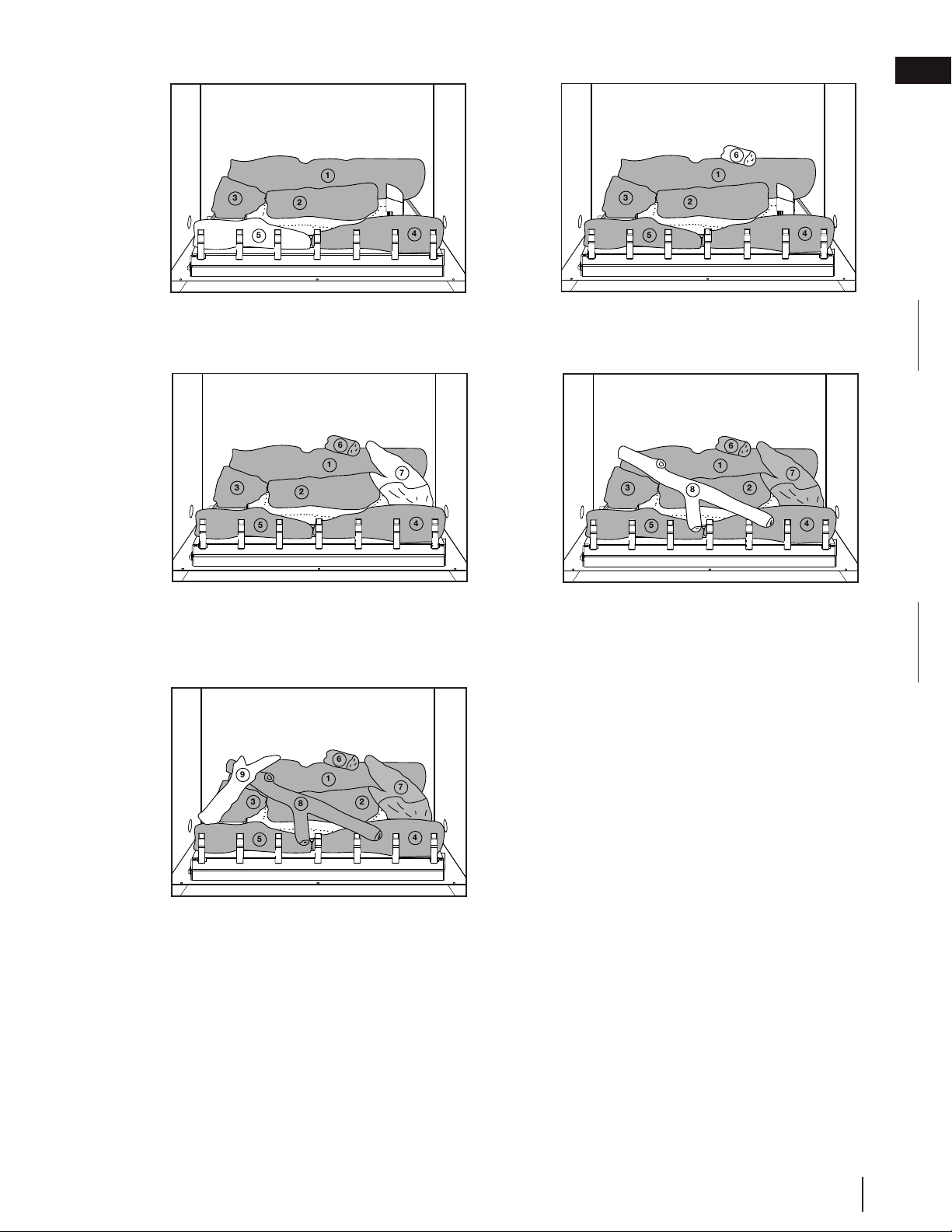
7. Place log #7 crosswise, ensuring the top rests
on the top right notch of log #1 and the bot-
tom rests on the rear notch of log #4.
8. Place log #8 crosswise, ensuring the top rests
on the top left notch of log #1, and the bottom
rests on both the top left notch of log #4 and
the top right notch of log #5.
9. Place log #9 crosswise, ensuring the top rests
on the top left notch of log #8 and the bottom
rests on the top left notch of log #5.
1
2
4
3
5
6
7
1
2
4
3
5
6
7
8
1
2
4
3
5
6
7
8
9
5. Place log #5 along the front left side of the
grate and then pull it forward, ensuring the log
notches align with the grate posts.
6. Place log #6 on the top notch of log #1,
ensuring the charcoal end of log #6 faces
forward.
1
2
4
3
5
1
2
4
3
5
6
EN
W415-1796 / A / 05.17.18
23
finishing
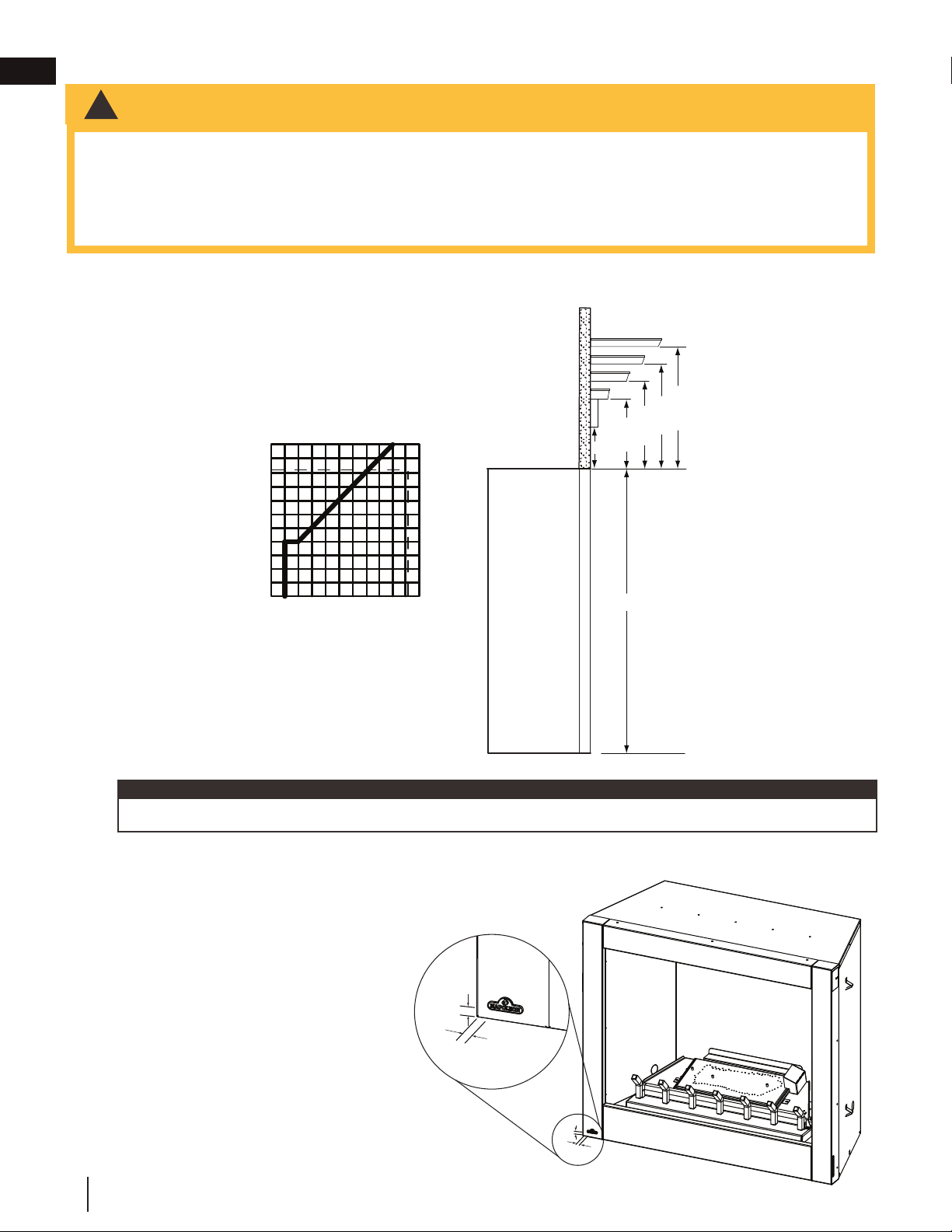
!
WARNING
• Risk of fire! Maintain all specified air space clearances to combustibles. Failure to comply with these
instructions may cause a fire or cause the appliance to overheat. Ensure all clearances (i.e. back, side, top,
vent, mantel, front, etc.) are clearly maintaned.
• Never obstruct the front opening of the appliance.
• When using paint or lacquer to finish the mantel, the paint or lacquer must be heat resistant to prevent
discolouration.
TOP OF
APPLIANCE
MANTEL
6”
4”
2”
20 1/2”
18 1/2”
16 1/2”
14 1/2”
35 3/4”
16 1/2
14 1/2
8
42
18 1/2
20 1/2
86 10
MANTEL
DEPTH
MANTEL
HEIGHT
1”
8”
8”
We recommend all mantels be made from non-combustible material. However, if using combustible materials,
follow the chart below.
9.3 minimum mantel clearances
Mantel temperatures will rise above normal temperatures and may be hot to touch.
note:
9.4 logo placement
½"
(12.7mm)
½"
(12.7mm)
½"
(12.7mm)
½"
(12.7mm)
Remove the backing of the logo supplied. Centre the
logo on the front of the appliance and ½” (12.7mm) in
from the left side, as shown.
W415-1796 / A / 05.17.18
EN
24
finishing
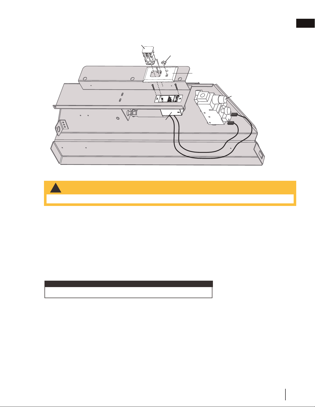
10.0 optional remote installation
A. Remove the battery pack from the receiver. Then by pulling down, remove the receiver cover and slide
the receiver into the hole located at the rear of the burner base. Secure using the two screws provided.
B. Secure the faceplate to the receiver with two of the screws provided.
C. Insert the battery pack (with batteries installed) through the opening in the faceplate and into the
receiver. The battery pack is secured and released with a catch mechanism. Push the receiver into the
catch to secure.
D. Insert the slide switch into its marked position on the faceplate.
E. Replace the existing switch wires connected to the terminals on the valve marked TH/TP and TH with
those running from the receiver.
RECEIVER
BATTERY
PACK
SLIDE
SWITCH
FACEPLATE
PRESS
TO OPEN
FIREPLACE REMOTE
OFF
ON
R
EMOTE
BA
T.LOW
VALVE
REAR BURNER BASE
The remote switch on the side of the appliance is no longer operational.
note:
• The transmitter and receiver are not waterproof. Ensure both components are not exposed to water.
!
WARNING
EN
W415-1796 / A / 05.17.18
25
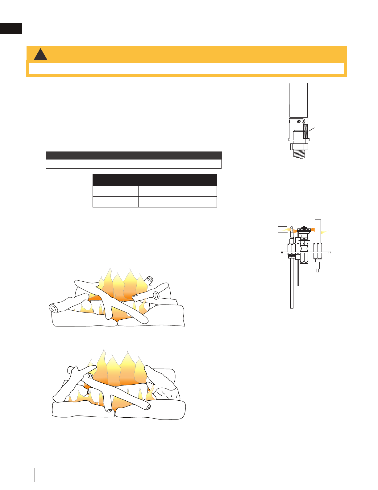
11.0 adjustments
11.1 venturi adjustment
11.2 flame characteristics
VENTURI ADJUSTMENT CHART
NG 1/8" (3.1mm)
P 3/16" (4.7mm)
!
WARNING
• Carbon can be distributed in surrounding living area if the air shutter is improperly adjusted.
33.2
It’s important to periodically perform a visual check of
the pilot and burner flames. Compare them to the
illustration provided. If any flames appear abnormal,
call a service person.
ADD IMAGE
HERE
36.1
3/8” - 1/2”
FLAME MUST
ENVELOP UPPER
3/8" TO 1/2"
(12.7mm - 9.5mm) OF
THERMOCOUPLE &
THERMOPILE
(9.5mm - 12.7mm)
This appliance has an air shutter that has been factory set open according to
the chart below:
Regardless of venturi orientation, closing the air shutter will cause a more
yellow flame, but can lead to carbonization. Opening the air shutter will cause
a more blue flame, but can cause flame lifting from the burner ports. The flame
may not appear yellow immediately; allow 15 to 30 minutes for the final flame
colour to be established.
AIR SHUTTER ADJUSTMENT MUST ONLY BE DONE BY A QUALIFIED
INSTALLER!
AIR
SHUTTER
OPENING
VENTURI
BURNER
ORIFICE
33.1
It is important that the orifice is securely inserted into the venturi.
note:
Birch Log Set BLKO36
Oak Log Set OLKO36
W415-1796 / A / 05.17.18
EN
26

12.0 maintenance
We recommend that the burner be inspected semi-annually by a qualified technician.
The burner must be replaced prior to the appliance being put into operation if it is evident that the burner is dam-
aged. Use only replacement parts as supplied by the appliance manufacturer.
24.3
!
WARNING
• Turn off the gas and electrical power before servicing the appliance.
• Appliance may be hot. Do not service until appliance has cooled.
• Do not use abrasive cleaners on glass.
• Do not paint the pilot assembly.
This appliance and its venting system should be inspected before use and at least annually by a qualifi ed
service person. The following suggested checks should be performed by a qualifi ed technician. The appliance
area must be kept clear and free of combustible materials, gasoline, or other fl ammable vapors and liquids.
The fl ow of combustion and ventilation air must not be obstructed.
1. In order to properly clean the burner and pilot assembly, remove the logs, rocks and/or glass to ex-
pose both assemblies.
2. Keep the control compartment, media, burner, air shutter opening and the area surrounding the appli-
ance clean by vacuuming or brushing, at least once a year.
3. Check to see that all burner ports are burning. Clean out any of the ports which may not be burning
or are not burning properly.
4. Check to see that the pilot fl ame is large enough to engulf the fl ame sensor and/or thermocouple /
thermopile as well as it reaches the burner.
5. If your appliance is equipped with a safety barrier, cleaning may be necessary due to excessive lint /
dust from carpeting, pets, etc. simply vacuum using the brush attachment.
6. If your appliance is equipped with relief doors, ensure the system performs effectively. Check that the
gasket is not worn or damaged. Replace if necessary.
7. Replace the cleaned logs, rocks or glass. Failure to properly position the media may cause carboning
which can be distributed in the surrounding living area, inside the fi rebox and on exterior surfaces sur-
rounding vent termination.
8. Check to see that the main burner ignites completely on all ports when turned on. A 5 to 10 second
total light-up period is satisfactory. If ignition takes longer, consult your local authorized dealer / dis-
tributor.
9. Visually inspect the appliance for carbon build up. Using a small whisk or brush, brush off the carbon
and vacuum up or sweep into garbage.
10. This step is not applicable for Vent Free appliances: Check to see that the appliance is vent-
ing correctly. Ensure chimney system is safe and unobstructed. (If for any reason the vent air intake
system is disassembled, re-install and re-seal per the instructions provided for the initial installation).
Caution: Label all wires prior to disconnection when servicing controls. Wiring errors can cause improper and
dangerous operation. Verify proper operation after servicing.
note:
EN
W415-1796 / A / 05.17.18
27
24.5
Stainless steel tends to oxidize or stain in the presence of chlorides and sulfi des, particularly in coastal areas and
other harsh environments, such as the warm, highly humid atmosphere around pools and hot tubs. These stains
could be perceived as rust, but can be easily removed or prevented. To provide stain prevention and removal,
wash all stainless steel surfaces every 3-4 weeks or as often as required with fresh water and/or stainless steel
cleaner.
CLEANING THE STAINLESS STEEL SURFACE:
Do not use abrasive cleaners or steel wool on the stainless steel parts. Doing so will scratch the fi nish. Surfaces
should be cleaned with warm soapy water while the metal is still warm to the touch. To clean stainless surfaces,
use a stainless steel or non-abrasive cleaner. Always wipe in the direction of the grain. Over time, stainless steel
parts discolour when heated, usually to a golden or brown hue. This discolouration is normal and does not affect
the performance of the appliance.

13.0 replacement parts
!
WARNING
26.2
• Failure to position the parts in accordance with this manual or failure to use only parts specifi cally approved
with this appliance may result in property damage or personal injury.
• **This is a fast acting thermocouple. It is an integral safety component. Replace only with a fast acting supplied
by Wolf Steel Ltd.
Contact your dealer for questions concerning prices and policies on replacement parts. Normally, all parts can
be ordered through your Authorized dealer / distributor.
For warranty replacement parts, a photocopy of the original invoice will be required to honour the
claim.
When ordering replacement parts always give the following information:
• Model & Serial Number of appliance
• Installation date of appliance
• Part number
• Description of part
• Finish
Parts, part numbers, and availability are subject to change without notice.
Parts identifi ed as stocked will be delivered within 2 to 5 business days for most delivery
destinations.
Parts not identifi ed as stocked will be delivered within a 2 to 4 week period, for most cases.
Parts identifi ed as ‘SO’ are special order and can take up to 90 days for delivery
W415-1796 / A / 05.17.18
EN
28
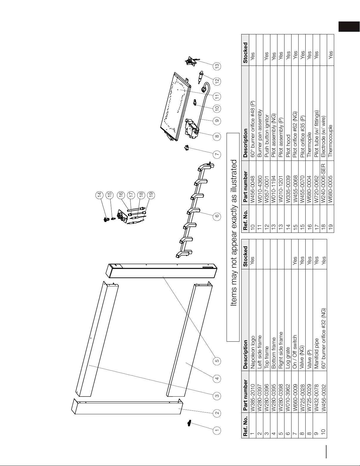
GSS36CF OVERVIEW
Ref. No.
Part number
Description
3
4
5
6
7
8
9
Ref. No.
Part number
Description
Items may not appear exactly as illustrated
2
1
Stocked
Stocked
W385-2010
Napoleon logo
12.01.17
Yes
13
W280-0397
Left side frame
W280-0396
Top frame
W280-0395
Bottom frame
W280-0398
Right side frame
W357-0001
Push button ignitor
W010-1194
Pilot assembly (NG)
1
2
3
4
5
6
7
9
8
11
12
13
31
30
29
28
26
25
19
18
17
16
15
14
W680-0004
W720-0062
W240-0006-SER
W680-0005
Thermopile
Pilot tube (w/ fittings)
Electrode (w/ wire)
Thermocouple
W335-0039
W455-0070
Pilot hood
Pilot orifice #62 (NG)
10
W725-0028
Valve (NG)
12
W660-0009
On / Off switch
11
W010-3962
Log grate
W455-0068
Pilot orifice #35 (P)
Yes
Yes
Yes
Yes
Yes
Yes
Yes
Yes
Yes
W010-4360
Burner pan assembly
10
W456-0048
60° burner orifice #48 (P)
Yes
Yes
W456-0032
60° burner orifice #32 (NG)
W432-0078
Manifold pipe
Yes
Yes
10
8
W725-0029
Valve (P)
Yes
14
15
16
18
17
15
19
Yes
13
W010-1201
Pilot assembly (P)
13.1 overview and valve train assembly
EN
W415-1796 / A / 05.17.18
29
replacement parts
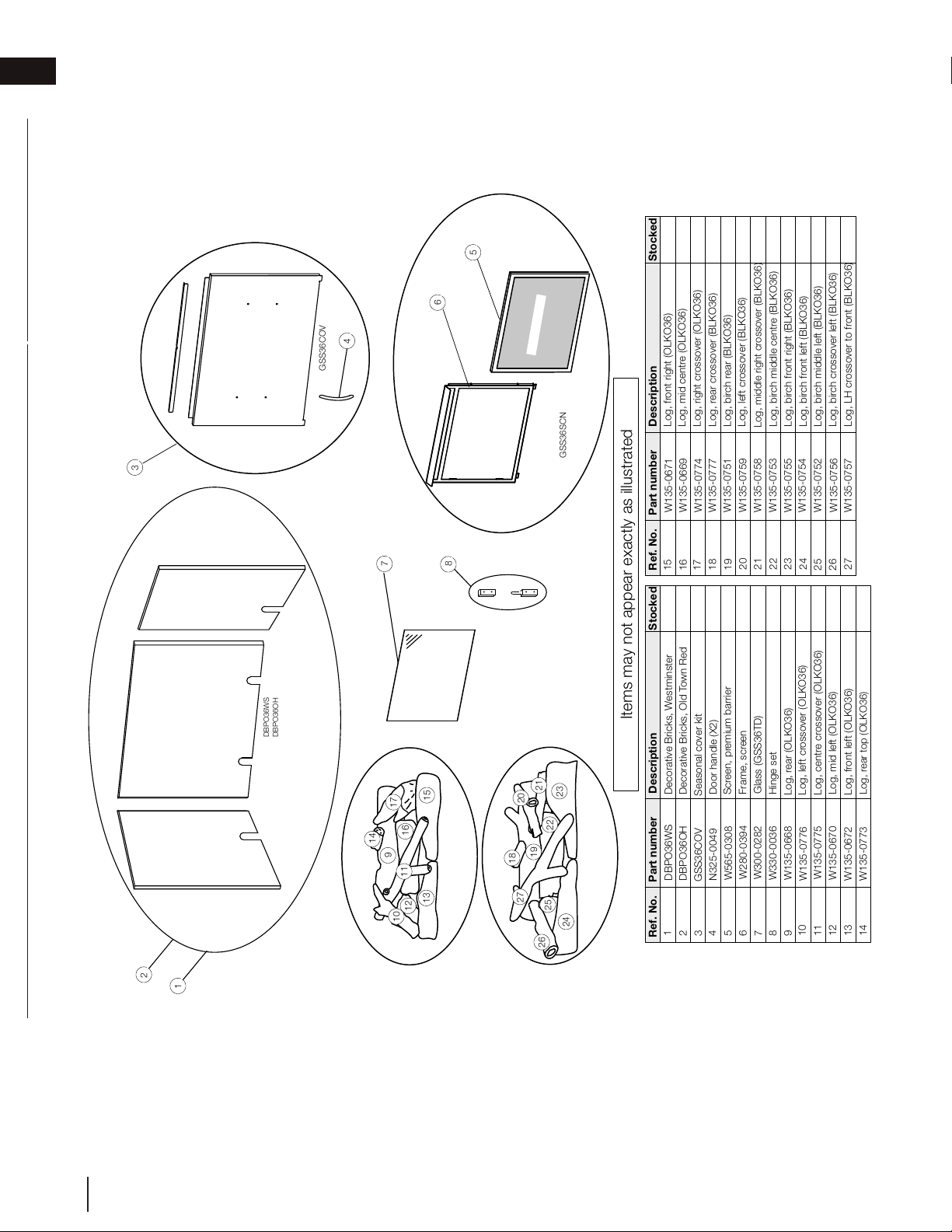
14.0 accessories
Ref. No.
Part number
Description
3
Ref. No.
Part number
Description
GSS36CF ACCESSORIES
Items may not appear exactly as illustrated
2
1
Stocked
Stocked
7
12.01.17
DBPO36WS
DBPO36OH
GSS36COV
Seasonal cover kit
4
3
8
3
N325-0049
Door handle (X2)
Yes
GSS36COV
4
5
6
9
10
11
12
13
W280-0394
W565-0308
W300-0282
Frame, screen
Screen, premium barrier
Glass (GSS36TD)
6
5
7
8
Safety Screen
GSS36SCN
Birch Log Set BLKO36
Oak Log Set OLKO36
14
15
16
17
18
19
20
21
22
23
24
25
26
16
13
14
12
11
9
10
17
15
19
18
20
21
23
22
27
24
26
25
1
DBPO36WS
Decorative Bricks, Westminster
DBPO36OH
Decorative Bricks, Old Town Red
W330-0036
Hinge set
27
2
W135-0668
W135-0776
W135-0775
W135-0670
W135-0672
W135-0773
W135-0671
W135-0669
W135-0774
W135-0777
W135-0751
W135-0759
W135-0758
W135-0753
W135-0755
W135-0754
W135-0752
W135-0756
W135-0757
Log, rear (OLKO36)
Log, left crossover (OLKO36)
Log, centre crossover (OLKO36)
Log, mid left (OLKO36)
Log, front left (OLKO36)
Log, rear top (OLKO36)
Log, front right (OLKO36)
Log, mid centre (OLKO36)
Log, right crossover (OLKO36)
Log, rear crossover (BLKO36)
Log, birch rear (BLKO36)
Log, left crossover (BLKO36)
Log, middle right crossover (BLKO36)
Log, birch middle centre (BLKO36)
Log, birch front right (BLKO36)
Log, birch front left (BLKO36)
Log, birch middle left (BLKO36)
Log, birch crossover left (BLKO36)
Log, LH crossover to front (BLKO36)
Yes
Yes
Yes
Yes
Yes
W415-1796 / A / 05.17.18
EN
30
accessories
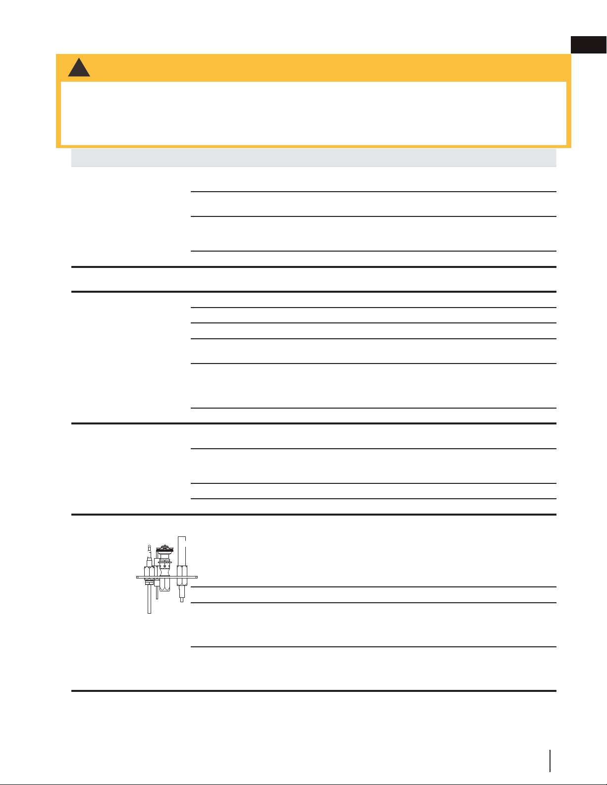
15.0 troubleshooting
SYMPTOM PROBLEM TEST SOLUTION
Main burner goes out; pilot
stays on.
Pilot flame is not large enough or
not engulfing the thermopile.
- Turn up the pilot flame.
- Replace pilot assembly.
Thermopile shorting. - Clean thermopile connection to the valve. Reconnect.
- Replace thermopile / valve.
Remote wall switch wire is too
long; too much resistance in the
system.
- Shorten wire to connect length or wire gauge.
Faulty thermostat or switch. - Replace.
Main burner goes out; pilot
goes out.
Refer to “MAIN BURNER GOES OUT; PILOT STAYS ON”
Pilot goes out when the gas
knob is released.
The gas valve has an inter-
lock device which will not
allow the pilot burner to be
lit until the thermocouple
has cooled. Allow approxi-
mately 60 seconds for the
thermocouple to cool.
System is not correctly purged. - Purge the gas line.
Out of propane gas. - Fill the tank.
Pilot flame is not large enough. - Turn up the pilot flame.
Pilot flame is not engulfing the
thermocouple
- Gently twist the pilot head to improve the flame pattern
around the thermocouple.
Thermocouple shorting / faulty. - Loosen and tighten thermocouple.
- Clean thermocouple and valve connection.
- Replace thermocouple.
- Replace valve.
Faulty valve. - Replace.
Pilot burning; no gas to main
burner; gas knob is on ‘HI’;
wall switch / thermostat is on.
Thermostat or switch is defective - Connect a jumper wire across the wall switch terminals; if
main burner lights, replace switch / thermostat.
Wall switch wiring is defective. - Disconnect the switch wires & connect a jumper wire across
terminals 1 & 3; if the main burner lights, check the wires for
defects and/or replace wires.
Main burner orifice is plugged. - Remove stoppage in orifice.
Faulty valve. - Replace.
Pilot will not light. No spark at pilot burner. - Check if pilot can be lit by a match.
- Check that the wire is connected to the push button igniter.
- Check if the push button igniter needs tightening.
- Replace the wire if the wire insulation is broken or frayed.
- Replace the electrode if the ceramic insulator is cracked or
broken.
- Replace the push button ignitor
Out of propane gas. - Fill the tank.
Spark gap is incorrect. - Spark gap should be 0.150” (3.8mm) to 0.175” (4.5mm)
from the electrode tip and the pilot burner. To ensure proper
electrode location, tighten securing nut (finger tight plus 1/4
turn).
No gas at the pilot burner. - Check that the manual valve is turned on.
- Check the pilot orifice for blockage.
- Replace the valve.
- Call the gas distributor.
PILOT
BURNER
THERMOCOUPLE
THERMOPILE
27.2
symptom problem test solution
Main burner fl ame is a
blue, lazy, transparent
fl ame.
Blockage in vent. - Remove blockage. In really cold conditions, ice buildup may occur on the
terminal and should be removed as required. To minimize this from happening
again, it is recommended that the vent lengths that pass through unheated
spaces (attics, garages, crawl spaces) be wrapped with an insulated mylar
sleeve. Prevent sleeve from sagging. Contact your local authorized dealer for
more information.
Main burner goes out;
pilot stays on.
Pilot fl ame is not large enough or
not engulfi ng the thermopile.
- Turn up the pilot fl ame.
- Replace pilot assembly.
Thermopile shorting. - Clean thermopile connection to the valve. Reconnect.
- Replace thermopile / valve.
Remote wall switch wire is too
long; too much resistance in the
system.
- Shorten wire to correct length or wire gauge.
Faulty thermostat or switch. - Replace.
Main burner goes out;
pilot goes out.
Refer to “MAIN BURNER GOES OUT; PILOT STAYS ON”
Vent is blocked - Check for vent blockage.
Vent is re-circulating - Check joint seals and installation
Flexible vent has become
disconnected from appliance.
- Re-attach to appliance.
- Cap was not replaced.
Flames are consistently
too large or too small.
Carboning occurs.
Appliance is over-fi red or
underfi red.
- Check pressure readings:
Inlet pressure can be checked by turning screw (A) counter-clockwise 2 or
3 turns and then placing pressure gauge tubing over the test point. Gauge
should read as described on the chart below. Check that main burner is
operating on ‘HI’. Outlet pressure can be checked the same as above using
screw (B). Gauge should read as described on the chart below. Check that
main burner is operating on ‘HI’. AFTER TAKING PRESSURE READINGS,
BE SURE TO TURN SCREWS CLOCKWISE FIRMLY TO RESEAL. DO
NOT OVER TORQUE.
Leak test with a soap and water solution.
Air shutter improperly adjusted. - Return air shutter to specifi ed opening, see “venturi adjustment” section.
Carbon is being
deposited on glass,
logs, rocks, media or
combustion chamber
surfaces.
Air shutter is blocked. - Ensure air shutter opening is free of lint or other obstructions.
Flame is impinging on the
glass, logs, rocks, media or
combustion chamber.
- Ensure the media is positioned correctly in the appliance.
- Open air shutter to increase the primary air.
- Check the input rate: check the manifold pressure and orifi ce size as specifi ed
by the rating plate.
- Ensure door gasketing is not broken or missing and the seal is tight.
- Ensure vent liners are free of holes and well sealed at all joints.
- Check that minimum rise per foot (meters) has been adhered to for any
horizontal venting.
White / grey fi lm forms. Sulphur from fuel is being
deposited on glass, logs or
combustion chamber surfaces.
- Clean the glass with a recommended gas fi replace glass cleaner. DO NOT
CLEAN GLASS WHEN HOT.
- If deposits are not cleaned off regularly, the glass may become permanently
marked.
Exhaust fumes smelled
in room, headaches.
Appliance is spilling.
(This is not applicable in outdoor
appliances)
- Check door seal.
- Check for exhaust damage.
- Check that venting is installed correctly.
- Room is in negative pressure; increase fresh air supply.
INSERT
PHOTO
OF VALVE
HERE
Pressure
Natural Gas
(inches)
Natural Gas
(millibars)
Propane
(inches)
Propane
(millibars)
Inlet
* 13”
(MIN. 4.5”)
17.4mb
(MIN. 11.2mb)
13”
(MIN. 11”)
32.4mb
(MIN. 27.4mb)
Outlet
3.5” 8.7mb 10” 24.9mb
* Maximum inlet
pressure not to
exceed 13”
!
WARNING
• Always light the pilot whether for the fi rst time or if the gas supply has run out, with the glass door open or
removed.
• Turn off gas and electrical power before servicing the appliance.
• Appliance may be hot. Do not service until appliance has cooled.
• Do not use abrasive cleaners
EN
W415-1796 / A / 05.17.18
31
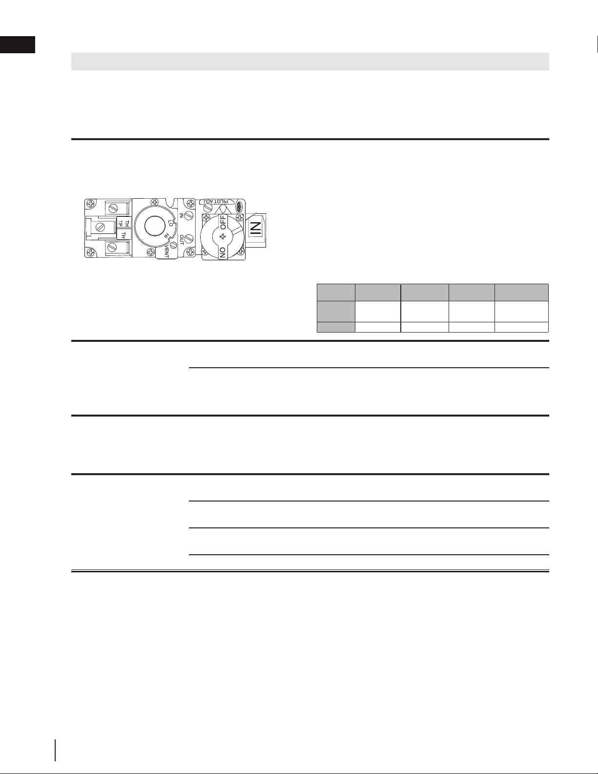
SYMPTOM PROBLEM TEST SOLUTION
Pilot goes out while
standing; Main burner is in
‘OFF’ position.
Gas piping is undersized. - Turn on all gas appliances and see if pilot flame
flutters, diminishes or extinguishes, especially when
main burner ignites. Monitor appliance supply working
pressure.
- Check if supply piping size is to code. Correct all
undersized piping.
Flames are consistently
too large or too small.
Carboning occurs.
Appliance is over-fired or
underfired.
- Check pressure readings:
- Inlet pressure can be checked by turning screw (A)
counter-clockwise 2 or 3 turns and then placing
pressure gauge tubing over the test point. Gauge
should read as described on the chart below. Check
that main burner is operating on ‘HI’.
- Outlet pressure can be checked the same as above
using screw (B). Gauge should read as described on
the chart below. Check that main burner is operating
on ‘HI’.
- AFTER TAKING PRESSURE READINGS, BE SURE TO
TURN SCREWS CLOCKWISE FIRMLY TO RESEAL.
DO NOT OVER TORQUE.
- Leak test with a soap and water solution.
Carbon is being deposited
on logs or combustion
chamber surfaces.
Air shutter has become
blocked.
- Ensure air shutter opening is free of lint or other
obstructions.
Flame is impinging on the
logs or combustion chamber.
- Check that the logs are correctly positioned.
- Open air shutter to increase the primary air.
- Check the input rate: check the manifold pressure and
orifice size as specified by the rating plate values.
White / grey film forms. Sulphur from fuel is being
deposited on glass, logs
or combustion chamber
surfaces.
- Clean the glass with a recommended gas appliance
glass cleaner.
- DO NOT CLEAN GLASS WHEN HOT.
- If deposits are not cleaned off regularly, the glass may
become permanently marked.
Remote wall switch is
in ’OFF’ position; main
burner comes on when
gas knob is turned to ‘ON’
position.
Wall switch is mounted up-
side down.
- Reverse.
Remote wall switch is
grounding.
- Replace.
Remote wall switch wire is
grounding.
- Check for ground (short); repair ground or replace wire.
Faulty valve. - Replace.
P
I
L
O
T
Pressure
Inlet
Outlet
Natural Gas
(inches)
Natural Gas
(millibars)
Propane
(inches)
Propane
(millibars)
*13"
(MIN. 4.5”)
3.5"
13"
(MIN. 11")
10"
17.4mb
(MIN. 11.2mb)
8.7mb
32.4mb
(MIN. 27.4mb)
24.9mb
W415-1796 / A / 05.17.18
EN
32
troubleshooting
2.2A
NAPOLEON warrants its products against manufacturing defects to the original purchaser only. Registering your
warranty is not necessary. Simply provide a proof of purchase along with the model number and serial number of the
appliance to make a warranty claim. Provided that the purchase was made through an authorized NAPOLEON dealer
your appliance is subject to the following conditions and limitations:
Warranty coverage begins on the date of original installation.
This limited warranty applies only while the appliance remains at the site of original installation, and only if the unit is
installed in Canada or the United States.
This factory warranty is non-transferable and may not be extended whatsoever by any of our representatives.
Installation must be done in accordance with the installation instructions included with the product and all local and
national building and fi re codes.
This limited warranty does not cover damages caused by misuse, lack of maintenance, accident, alterations, abuse, or
neglect and parts installed from other manufacturers will nullify this warranty.
This limited warranty further does not cover any scratches, dents, corrosion, or discolouring caused by excessive
heat, abrasive and chemical cleaners, mechanical breakage of logs and embers.
In the fi rst year only, this warranty extends to the repair or replacement of warranted parts which are defective in
material or workmanship provided that the product has been operated in accordance with the operation instructions
and under normal conditions.
After the fi rst year, with respect to this Limited Warranty, NAPOLEON may, at its discretion, fully discharge all
obligations with respect to this warranty by refunding to the original warranted purchaser the wholesale price of any
warranted but defective part(s).
After the fi rst year, NAPOLEON will not be responsible for installation, labour, or any other costs or expenses related to
the reinstallation of a warranted part, and such expenses are not covered by this warranty.
Notwithstanding any provisions contained in this Limited Warranty, NAPOLEON’S responsibility under this warranty is
defi ned as above and it shall not in any event extend to any incidental, consequential, or indirect damages.
This warranty defi nes the obligations and liability of NAPOLEON with respect to the NAPOLEON gas appliance and
any other warranties expressed or implied with respect to this product; its components or accessories are excluded.
This limited warranty does not cover damages resulting from the use of components not supplied with the appliance
or the use of fuel other than those specifi ed.
Any damages to appliance due to weather, long periods of dampness, condensation, damaging chemicals, or cleaners
will not be the responsibility of NAPOLEON.
NAPOLEON reserves the right to have its representative inspect any product or part thereof prior to honouring any
warranty claim.
All parts replaced under the Limited warranty policy are subject to a single claim.
All parts replaced under the warranty will be covered for a period of 90 days from the date of their installation.
The manufacturer may require that defective parts or products be returned or that digital pictures be provided to
support the claim. Returned products are to be shipped prepaid to the manufacturer for investigation. If a product is
found to be defective, the manufacturer will repair or replace such defect.
Before shipping your appliance or defective components, your dealer must obtain an authorization number. Any
merchandise shipped without authorization will be refused and returned to sender.
Shipping costs are not covered under this warranty.
Additional service fees may apply if you are seeking warranty service from a dealer.
Labour, travel, diagnostic tests, shipping, and other related charges are not covered by this warranty.
NAPOLEON gas appliances are manufactured under the strict Standard of the world recognized
ISO 9001 : 2015 Quality Management System.
NAPOLEON products are designed with superior components and materials, assembled by trained craftsmen who take
great pride in their work. The burner and valve assembly are leak and test-fi red at a quality test station. Once assembled,
the complete appliance is thoroughly inspected by a qualifi ed and authorized installer, service agency, or supplier before
packaging to ensure that you, the customer, receives the quality product that you expect from NAPOLEON.
All stainless steel components of your new NAPOLEON gas appliance are warranted against defects for
fi ve years.
Electrical (110V) components and wearable parts are covered and NAPOLEON will provide replacement parts free of
charge during the fi rst year of the limited warranty. This covers: gas valves, logs, and gasketing.*
Labour related to warranty repair is covered free of charge during the fi rst year. Repair work, however,
requires the prior approval of an authorized company offi cial. Labour costs to the account of NAPOLEON
are based on a predetermined rate schedule and any repair work must be done through an authorized
NAPOLEON dealer.
* Construction of models vary. Warranty applies only to components included with your specifi c appliance.
Napoleon Gas Appliance 5 Year Limited Warranty
Conditions and Limitations
All specifi cations and designed are subject to change without prior notice due to on-going product improvements. Napoleon is a registered
trademark of Wolf Steel Ltd.
16.0 warranty
EN
W415-1796 / A / 05.17.18
33
NAPOLEON CELEBRATING OVER 40 YEARS
OF HOME COMFORT PRODUCTS
7200, Route Transcanadienne, Montréal, Québec H4T 1A3
24 Napoleon Road, Barrie, Ontario, Canada L4M 0G8
214 Bayview Drive, Barrie, Ontario, Canada L4N 4Y8
103 Miller Drive, Crittenden, Kentucky, USA 41030
Phone: 1-866-820-8686
napoleonproducts.com