Loading ...
Loading ...
Loading ...
23
CONVERSIONS
REPLACING THE INJECTORS
Our burners can be adapted to different types of
gas by simply installing the injectors suitable for the
gas you want to use. To help the installer, the table
(see paragraph «
TECHNICAL FEATURES») gives
the burner nominal heat input, injector diameter and
operating pressure of the different gas types.
Comply with the following instructions:
Injector replacement - Hob burners.
To change the injectors on the hob, remove
the burner cup and head and with a 7 mm
Ø socket spanner replace them (g. 20).
After having replaced the injectors, it will be
necessary to proceed with burner adjustment
as explained in the previous paragraphs. The
technician must replace any seals after the
adjustments have been made.
20
ADJUSTMENTS
• All seal must be replaced by the technician
following any adjustment or regulation.
• The adjustment of the reduce rate (simmer)
must be undertaken only with burners
functioning on natural gas while in the case of
burners functioning on L.P.G, the screw must
be locked down fully (in clockwise direction).
• “Primary air adjustment” on hob gas burners
is unnecessary.
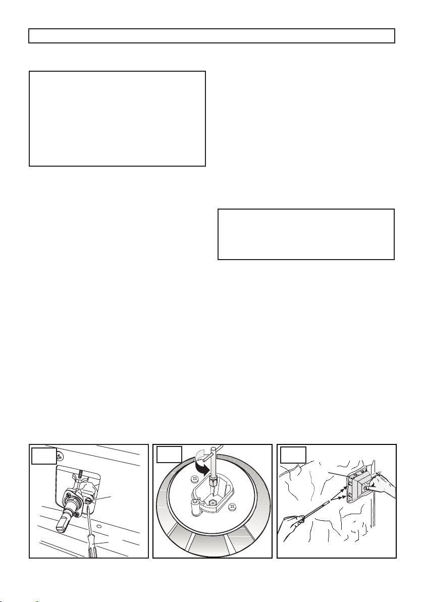
TAPS
All gas taps are male cone type with only one way of
passage. Adjustment of the “Reduced rate” position
as follows:
• Turn the burner on and place the knob on the
“Reduced rate” position (small ame).
• Remove the knob of the tap which is attached by
simply applying pressure to the rod.
• Insert a small screwdriver (C) into screw (V) side
of the stem (g. 19) and turn to the right or left
the throttling cone until the ame of the burner is
conveniently regulated to the Low position.
• Check that the ame does not go out when the knob
is sharply switched from the “Full on” to “Reduced
rate” positions.
• ATTENTION!! This operation can be carried out
also with the front panel tted, but if the technician
nds some difculties to reach the adjustment
screw, remove the front panel unscrewing the xing
screws (Vf) (g. 24), which are positioned in the
inferior part of the same.
INSTRUCTIONS FOR THE INSTALLER
19
CHANGING THE FLEXIBLE GAS HOSE
In order to guarantee that the gas hose is always in
excellent condition we strongly recommend changing
it on the date you will nd printed on it.
21
REPLACING THE ELECTRICAL COMPONENTS
• The rear protection will have to be removed in order
to change the electrical heating elements, spit
motor, terminal board and power cable.
• If you have to change the power cable (see the
cross section on table paragraph «TECHNICAL
FEATURES»), always keep the earth wire longer
than the phase wires and, in addition, follow
all the instructions given in the «ELECTRICAL
CONNECTION» paragraph.
• To change the oven lamp see the instructions on
the REPLACING THE OVEN LAMP paragraph.
• To change the lamp holder, remove the side
panels and then use a screwdriver to push the two
locking tabs (g. 21) and remove the lamp holder
from the inside of the oven.
Loading ...