
IMPORTANT SAFETY INSTRUCTIONS
Carefully read the following Important information redarding installation
safety and maintenance. Keep these instruction for future reference.
ISLAND RANGE HOOD USER MANUAL
I N S P I R I N G T H E W O R L D ’ S K I T C H E N
ISLAND RANGE HOODS
INSTALL USE & CARE GUIDE
INSTALLATION INSTRUCTIONS
Rev. 23.06
a
n
y
b
r
a
n
d
s
a
n
d
p
r
o
d
u
c
t
s
t
o
c
h
o
o
s
e
f
r
o
m
a
n
d
w
e
a
r
e
h
o
n
o
r
e
d
t
o
k
n
o
w
t
h
a
t
y
o
u
h
a
v
e
d
e
c
i
d
e
d
t
o
t
a
k
e
o
n
e
o
f
o
u
r
p
r
o
d
u
c
t
s
i
n
t
o
y
o
u
r
h
o
m
e
a
n
d
h
o
p
e
t
h
a
t
y
o
u
e
n
j
o
y
i
t
.
COSMO appliances are designed according to the strictest safety
and performance standard for the North American market. We
follow the most advanced manufacturing philosophy. Each appli-
ance leaves the factory after thorough quality inspection and test-
ing. Our distributors and our service partners are ready to answer
any questions you may have regarding how to install, use and care
for your products. We hope that this manual will help you learn to
use the product in the safest and most effective manner .
If you have any questions or concerns, please contact the dealer
from whom you purchased it, or contact our Customer Support at:
1-888-784-3108.
Please read the important safety instructions before using the product
for your own safety and to reduce the risk of fire or electrical shock, etc.
Please keep this manual for future use. THANK YOU
Thank you for your purchase. We know that you have many brands and
products to choose from and we are honored to know that you have decided
to take one of our products into your home and hope that you enjoy it.
About Your New Filters
Stainless Steel Baffle Filters do not need linings or mesh inside of
the filters and are completely constructed out of stainless steel.
The stainless steel construction allows them to be used again
after being cleaned or going through the dishwasher.
How do Baffle Filters Work?
They function by forcing the grease filled air to quickly and
continuously change direction as it passes through the filter. The
grease is unable to change direction as fast as the air carrying
them, they end up getting caught on the metal blades and then
trapped into the filter tray.These filters are both efficient and
require less maintenance.
* See pages 19-20 for cleaning and installation information.
STAINLESS STEEL BAFFLE FILTERS
THANK YOU FOR YOUR PURCHASE
2 3

a
n
y
b
r
a
n
d
s
a
n
d
p
r
o
d
u
c
t
s
t
o
c
h
o
o
s
e
f
r
o
m
a
n
d
w
e
a
r
e
h
o
n
o
r
e
d
t
o
k
n
o
w
t
h
a
t
y
o
u
h
a
v
e
d
e
c
i
d
e
d
t
o
t
a
k
e
o
n
e
o
f
o
u
r
p
r
o
d
u
c
t
s
i
n
t
o
y
o
u
r
h
o
m
e
a
n
d
h
o
p
e
t
h
a
t
y
o
u
e
n
j
o
y
i
t
.
COSMO appliances are designed according to the strictest safety
and performance standard for the North American market. We
follow the most advanced manufacturing philosophy. Each appli-
ance leaves the factory after thorough quality inspection and test-
ing. Our distributors and our service partners are ready to answer
any questions you may have regarding how to install, use and care
for your products. We hope that this manual will help you learn to
use the product in the safest and most effective manner .
If you have any questions or concerns, please contact the dealer
from whom you purchased it, or contact our Customer Support at:
1-888-784-3108.
Please read the important safety instructions before using the product
for your own safety and to reduce the risk of fire or electrical shock, etc.
Please keep this manual for future use. THANK YOU
Thank you for your purchase. We know that you have many brands and
products to choose from and we are honored to know that you have decided
to take one of our products into your home and hope that you enjoy it.
About Your New Filters
Stainless Steel Baffle Filters do not need linings or mesh inside of
the filters and are completely constructed out of stainless steel.
The stainless steel construction allows them to be used again
after being cleaned or going through the dishwasher.
How do Baffle Filters Work?
They function by forcing the grease filled air to quickly and
continuously change direction as it passes through the filter. The
grease is unable to change direction as fast as the air carrying
them, they end up getting caught on the metal blades and then
trapped into the filter tray.These filters are both efficient and
require less maintenance.
* See pages 19-20 for cleaning and installation information.
STAINLESS STEEL BAFFLE FILTERS
THANK YOU FOR YOUR PURCHASE
2 3
4 5
SAFETY
PARTS DIAGRAM
INSTALLATION REQUIREMENTS
LOCATION REQUIREMENTS
VENTILATION REQUIREMENTS
RANGE HOOD USE
LED LIGHT REPLACEMENT
DUCTLESS CONVERSION
OIL CUP INSTALLATION
CONTROL PANEL OPERATION
MAINTENANCE
PERMANENT FILTERS INSTALLATION
TROUBLESHOOTING
WARRANTY
5
flambéing food.
6
7
8
9-10
11-13
14
15
16
17
19
20
21
24-25
RANGE HOOD INSTALLATION
18
IMPORTANT SAFETY INSTRUCTIONS
TABLE OF CONTENTS
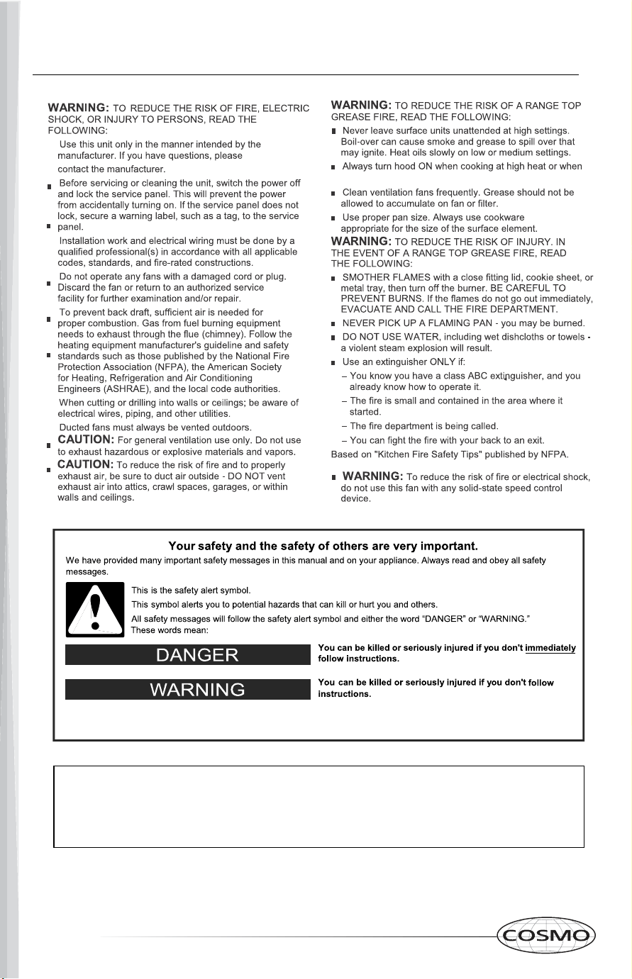
WARNING: This appliance is intended for normal indoor residential use. It is not
approved for commercial use, outdoor installation, installation over an outdoor BBQ
grill, or any other application not specifically allowed by this manual. Damage from
improper installation or use of this appliance is not covered by the product warranty.
4 5
SAFETY
PARTS DIAGRAM
INSTALLATION REQUIREMENTS
LOCATION REQUIREMENTS
VENTILATION REQUIREMENTS
RANGE HOOD USE
LED LIGHT REPLACEMENT
DUCTLESS CONVERSION
OIL CUP INSTALLATION
CONTROL PANEL OPERATION
MAINTENANCE
PERMANENT FILTERS INSTALLATION
TROUBLESHOOTING
WARRANTY
5
flambéing food.
6
7
8
9-10
11-13
14
15
16
17
19
20
21
24-25
RANGE HOOD INSTALLATION
18
IMPORTANT SAFETY INSTRUCTIONS
TABLE OF CONTENTS
WARNING: This appliance is intended for normal indoor residential use. It is not
approved for commercial use, outdoor installation, installation over an outdoor BBQ
grill, or any other application not specifically allowed by this manual. Damage from
improper installation or use of this appliance is not covered by the product warranty.
6 7
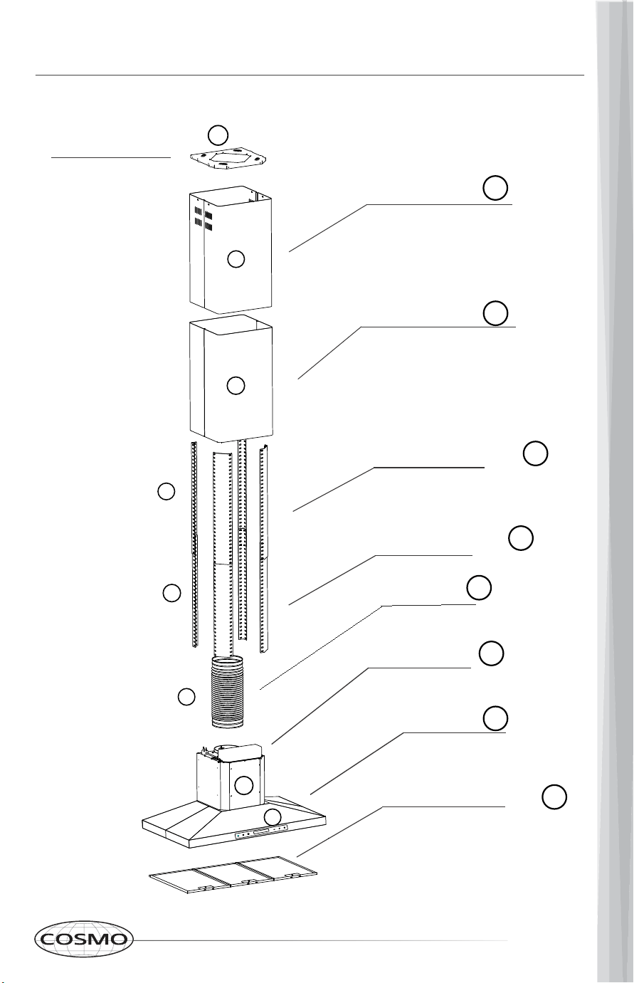
Lower Support Frame
Upper Support Frame
Outer Chimney
Inner Chimney
Stainless Steel Baffle Filters
Main Body
Blower Assembly
Ceiling Mount
A
B
C
D
E
F
G
H
30
4
4
1
2
8
13
13
8
42
6
36
45
Damper Flap
2
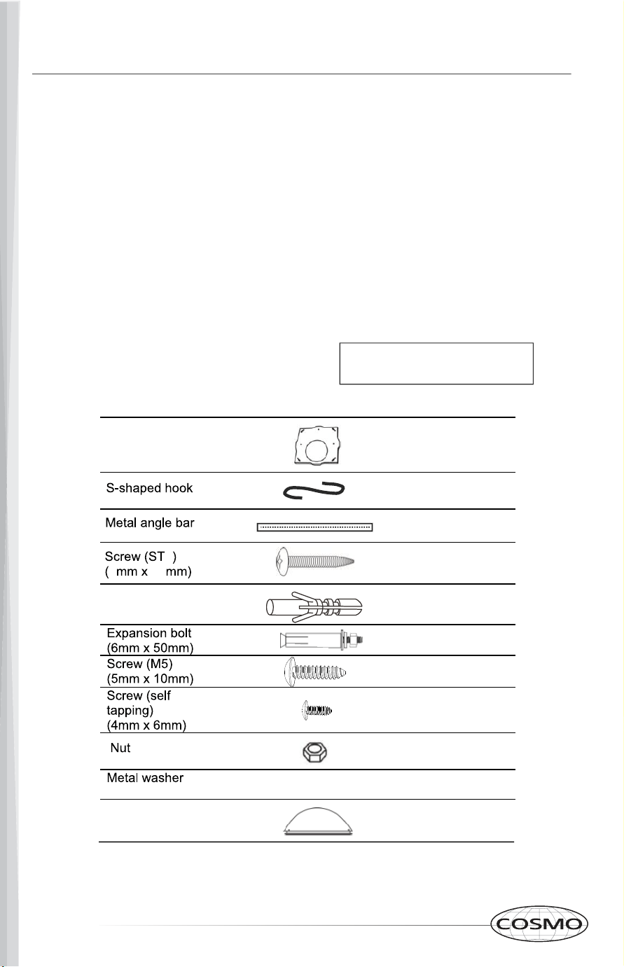
Wall Anchor
ST4x6
(A) Ceiling Mount
(B) Inner Chimney
(C) Outer Chimney
(D) Upper Support Frame
(E) Lower Support Frame
(F) Ducting Hose
(G) Blower Assembly
(H) Main Body
(I) Baffle Filters
Hardware
Ceiling Mount (A)
Ducting Hose
I
F
E
D
G
H
C
B
PARTS SUPPLIED
* Hardware content may vary
from model to model
Oil Cup
(D / E)
1
TOOLS AND PARTS
REQUIREMENTS
Electric Drill or Ratchet Driver
1/2" drill bit for drilling pilot holes
1 1/4" drill bit for drilling electrical wiring
access hole
Screwdrivers; Phillips & Flat Head
Pliers
Tape measure or ruler and pencil
Electrical supplies for wiring
Aluminum foil tape and/or Duct Tape
Hammer
Jigsaw or Saber Saw
Stud Finder
PARTS DIAGRAM
INSTALLATION REQUIREMENTS
6 7
Lower Support Frame
Upper Support Frame
Outer Chimney
Inner Chimney
Stainless Steel Baffle Filters
Main Body
Blower Assembly
Ceiling Mount
A
B
C
D
E
F
G
H
30
4
4
1
2
8
13
13
8
42
6
36
45
Damper Flap
2
Wall Anchor
ST4x6
(A) Ceiling Mount
(B) Inner Chimney
(C) Outer Chimney
(D) Upper Support Frame
(E) Lower Support Frame
(F) Ducting Hose
(G) Blower Assembly
(H) Main Body
(I) Baffle Filters
Hardware
Ceiling Mount (A)
Ducting Hose
I
F
E
D
G
H
C
B
PARTS SUPPLIED
* Hardware content may vary
from model to model
Oil Cup
(D / E)
1
TOOLS AND PARTS
REQUIREMENTS
Electric Drill or Ratchet Driver
1/2" drill bit for drilling pilot holes
1 1/4" drill bit for drilling electrical wiring
access hole
Screwdrivers; Phillips & Flat Head
Pliers
Tape measure or ruler and pencil
Electrical supplies for wiring
Aluminum foil tape and/or Duct Tape
Hammer
Jigsaw or Saber Saw
Stud Finder
PARTS DIAGRAM
INSTALLATION REQUIREMENTS
8 9
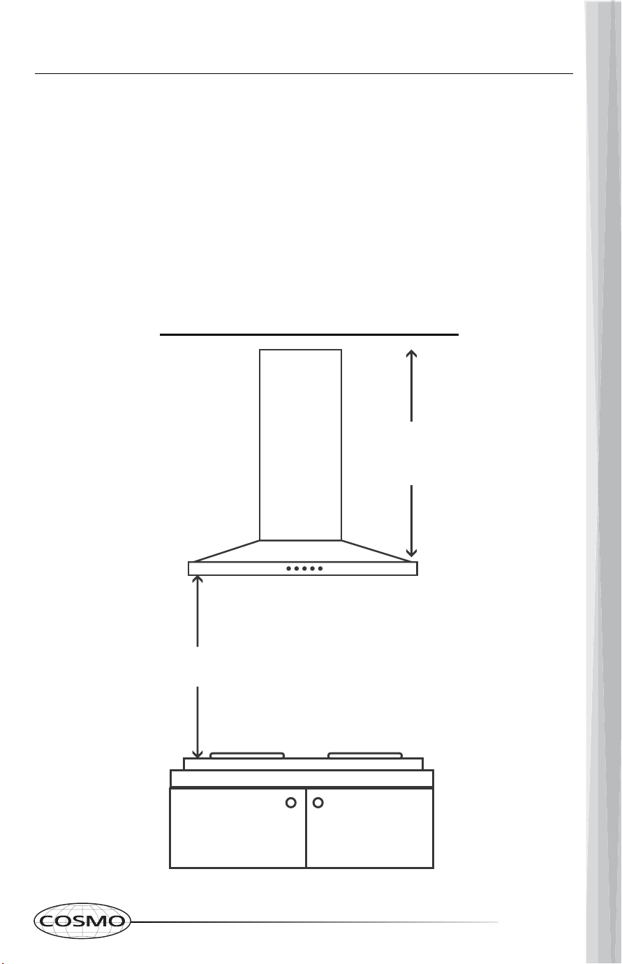
IMPORTANT: Please observe all governing codes and ordinances. It is
recommended that a qualified technician install the range hood. It is the
installer's responsibility to comply with installation clearances specified
on the model / product rating label.
Range hood's location should be away from strong draft areas such as;
windows, doors and strong heating vents.
Cabinet opening dimensions that are shown must be used. Given
dimensions provide minimum clearance.
LOCATION REQUIREMENTS
INSTALLATION DIMENSIONS
24”-36”
26.3”
to
46”
Minimum Drop -
Down Height: 30.75"
Ceiling Height: 8-9 Feet
VENTILATION REQUIREMENTS
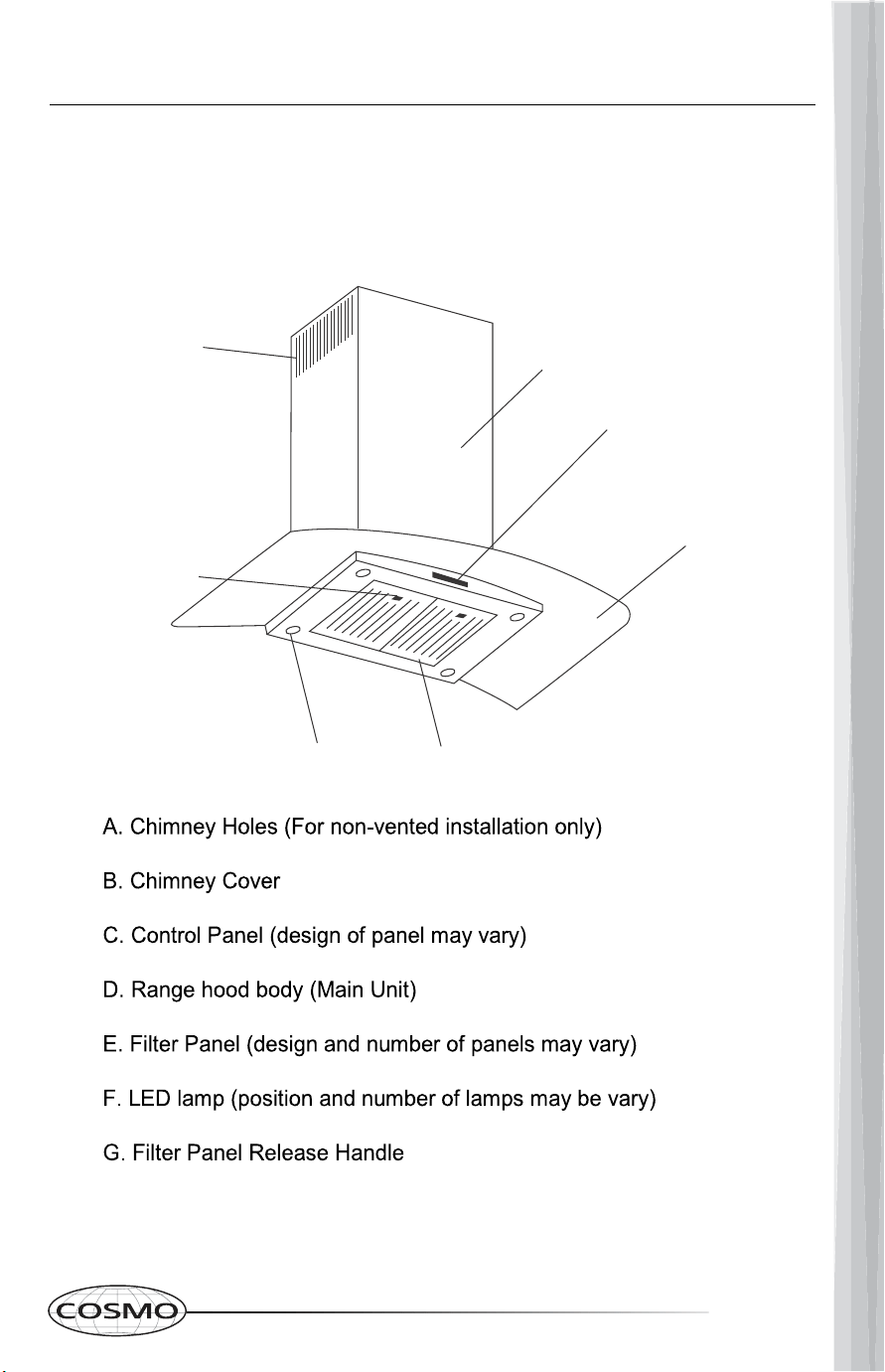
A. Chimney hole
B. 6" (15.2 cm) round vent
A. Roof cap
B. 6" (15.2 cm) round vent
Part CFK1-TM is required (Sold Separately).
This range hood is factory set for through
the roof or wall.
Rear Venting
For Ductless (Recirculating)
Installations
chimney vent holes. See Page 16 for
ductless conversion instructions.
8 9
IMPORTANT: Please observe all governing codes and ordinances. It is
recommended that a qualified technician install the range hood. It is the
installer's responsibility to comply with installation clearances specified
on the model / product rating label.
Range hood's location should be away from strong draft areas such as;
windows, doors and strong heating vents.
Cabinet opening dimensions that are shown must be used. Given
dimensions provide minimum clearance.
LOCATION REQUIREMENTS
INSTALLATION DIMENSIONS
24”-36”
26.3”
to
46”
Minimum Drop -
Down Height: 30.75"
Ceiling Height: 8-9 Feet
VENTILATION REQUIREMENTS
A. Chimney hole
B. 6" (15.2 cm) round vent
A. Roof cap
B. 6" (15.2 cm) round vent
Part CFK1-TM is required (Sold Separately).
This range hood is factory set for through
the roof or wall.
Rear Venting
For Ductless (Recirculating)
Installations
chimney vent holes. See Page 16 for
ductless conversion instructions.
10 11
ELECTRICAL REQUIREMENTS
Vent Piece
6" (15.2cm) Round
45° elbow 2.5 ft
90° elbow 5.0 ft
Maximum equivalent vent length is 35 ft
Example vent system
The following example falls within the
maximum recommended vent length
of 35 ft
1 - 90° elbow = 5.0 ft
1 - wall cap = 0.0 ft
6 ft straight tube = 6.0 ft
Length of system = 11.0 ft
Install the ducting hose (F)
COMPLETE PREPARATION
RANGE HOOD INSTALLATION
Air outlet
Ducting Hose
1.
2.
3.
4.
4-3/16
12 13
WARNING
[1] 13 pcs ST4 x 30 Wood Screws + 13 Wall Anchors for Wood Mounting
[2] 8 pcs M6x50 Expansion Bolts for concrete Mounting
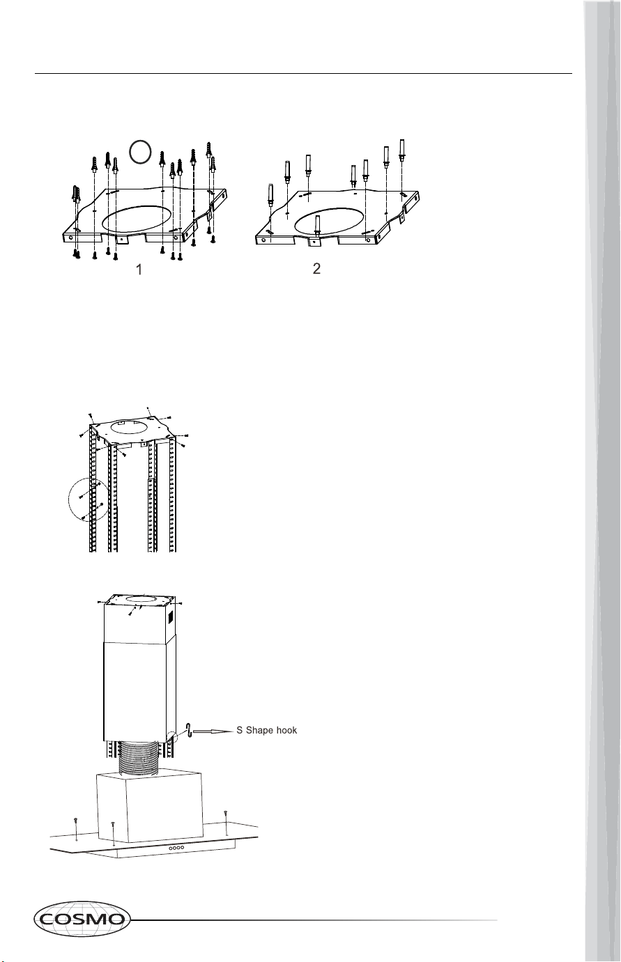
2. Attach the Angle Bars to the Ceiling Mount (A) using (8) M5 screws. Extend the
Angle Bars to the required height and secure them using (16) M5 screws with nuts &
metal washers.
A
B
C
D
E
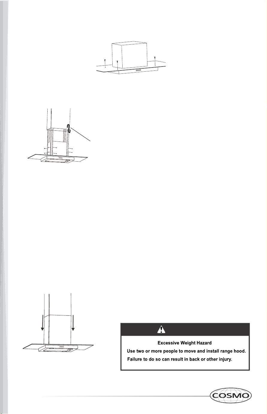
4. If the glass canopy has not been pre-assembled by the factory, then it should
be attached to the top of the main body of the range hood at this stage.
5. Lift the main body (G/H) of the range hood onto the support frames (D/E)
and fix into position using [16] M5 screws.
IMPORTANT: This stage of the installation process
MUST be completed by two people.
The screws MUST be securely tightened.
6. If you are going to be using the hood in extraction mode (ducted), you should
attach the ducting hose to the ceiling.
The electrical connection must correspond to the electrical requirements noted
on the rating plate which is inside the range hood. The appliance should now be
connected to the power supply.
Check that the appliance is operating correctly by selecting each speed and
switching the lights on and off.
Remove the hanging hook and slide the lower chimney section down until it rests
against the main body of the range hood.
Use a stainless steel cleaner to clean your hood after successful installation.
3. If your Island Range Hood is going
to be used in ducted mode, connect
the ducting hose (F) to the Ceiling
Mount (A) at this point.
Fix the Upper Chimney (B) to the
Ceiling Mount (A) using (4) ST4x6 self
tapping screws.
Slide the Lower Chimney (C) onto the
Support Frames (D/E) and raise it
until it sits just below the Upper
Chimney (B) section.
F
G
H
1. Position the (A) Ceiling Mount on the ceiling and mark the position of the
screw holes. The mount should be securely attached to the ceiling.
AA
RANGE HOOD INSTALLATION
IMPORTANT: The angle bars must have an overlap
of AT LEAST 100mm/4"
The "S" hook Holds the lower chimney
up while the main body is lifted and
fixed to the support frame in step 5.
* One end hooks onto the support
frame, and the other end (bottom of
the S) holds the the lower chimney up
Use the S hook to keep the lower chimney in place by
attaching it to the support frame for this step.
12 13
WARNING
[1] 13 pcs ST4 x 30 Wood Screws + 13 Wall Anchors for Wood Mounting
[2] 8 pcs M6x50 Expansion Bolts for concrete Mounting
2. Attach the Angle Bars to the Ceiling Mount (A) using (8) M5 screws. Extend the
Angle Bars to the required height and secure them using (16) M5 screws with nuts &
metal washers.
A
B
C
D
E
4. If the glass canopy has not been pre-assembled by the factory, then it should
be attached to the top of the main body of the range hood at this stage.
5. Lift the main body (G/H) of the range hood onto the support frames (D/E)
and fix into position using [16] M5 screws.
IMPORTANT: This stage of the installation process
MUST be completed by two people.
The screws MUST be securely tightened.
6. If you are going to be using the hood in extraction mode (ducted), you should
attach the ducting hose to the ceiling.
The electrical connection must correspond to the electrical requirements noted
on the rating plate which is inside the range hood. The appliance should now be
connected to the power supply.
Check that the appliance is operating correctly by selecting each speed and
switching the lights on and off.
Remove the hanging hook and slide the lower chimney section down until it rests
against the main body of the range hood.
Use a stainless steel cleaner to clean your hood after successful installation.
3. If your Island Range Hood is going
to be used in ducted mode, connect
the ducting hose (F) to the Ceiling
Mount (A) at this point.
Fix the Upper Chimney (B) to the
Ceiling Mount (A) using (4) ST4x6 self
tapping screws.
Slide the Lower Chimney (C) onto the
Support Frames (D/E) and raise it
until it sits just below the Upper
Chimney (B) section.
F
G
H
1. Position the (A) Ceiling Mount on the ceiling and mark the position of the
screw holes. The mount should be securely attached to the ceiling.
AA
RANGE HOOD INSTALLATION
IMPORTANT: The angle bars must have an overlap
of AT LEAST 100mm/4"
The "S" hook Holds the lower chimney
up while the main body is lifted and
fixed to the support frame in step 5.
* One end hooks onto the support
frame, and the other end (bottom of
the S) holds the the lower chimney up
Use the S hook to keep the lower chimney in place by
attaching it to the support frame for this step.
14 15
1. Switch the unit off and unplug the range hood.
2. Remove the lamp cover by unscrewing the 2 screws.
3. Unscrew the LED light.
4. Replace with the same type and rated light.
LED light (max, 1.5w)
The range hood is designed to remove smoke, vapors and odors. For
best results, start the hood before cooking. After the process is complete,
allow the range hood to run for several minutes to completely clear all
the smoke and odors from the kitchen.
RANGE HOOD USE
REPLACING LED BULBS
A
C
B
D
E
F
G
16 17
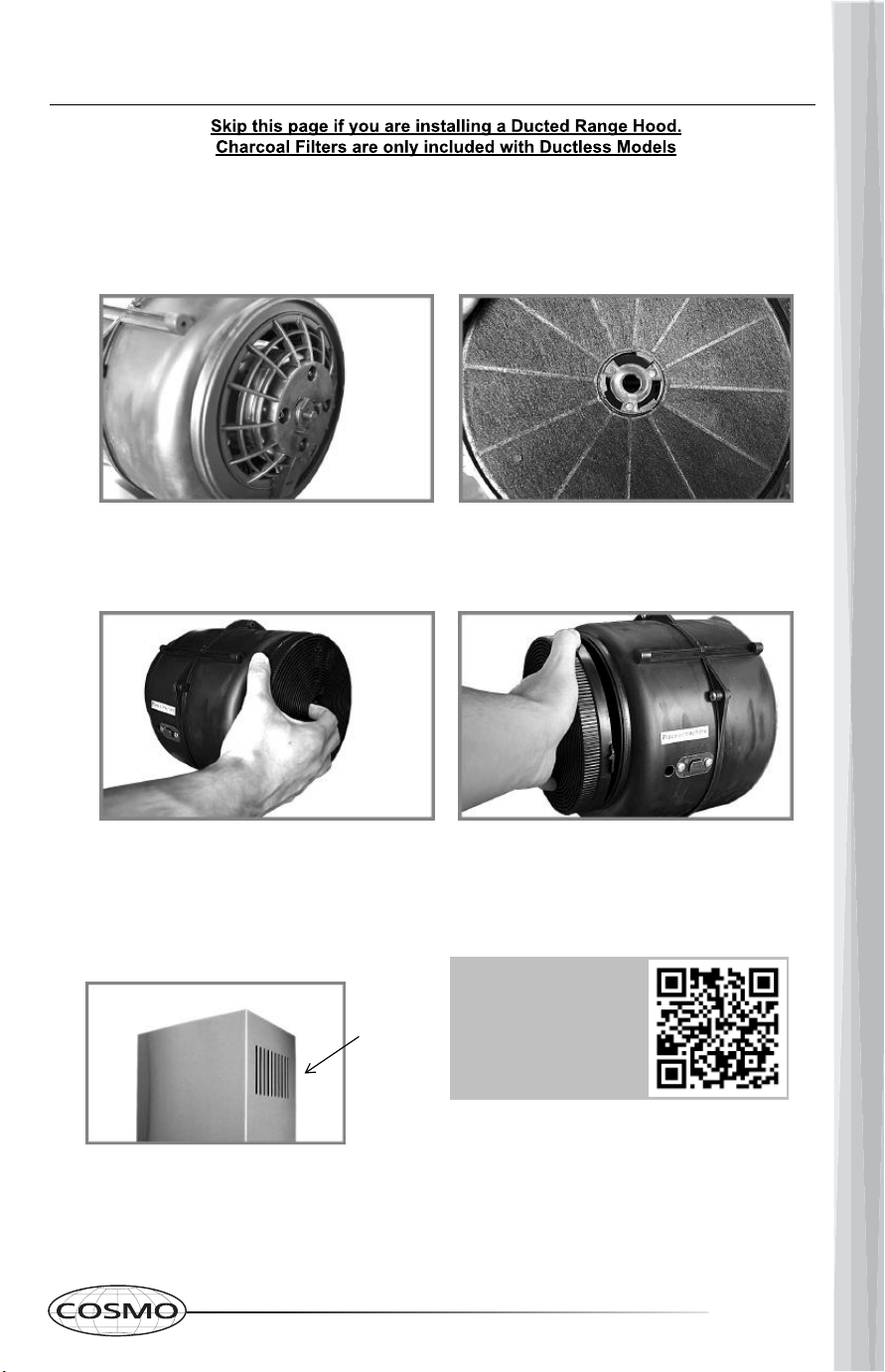
It is recommended that the charcoal filter be replaced every 4-6 months. Charcoal
filter replacements are available for purchase at: www.cosmoappliances.com
Charcoal Filter Kit Part# CFK1-TM
Step 1: Remove the ARC-FLOW Baffle Filters.
Step 2: Locate the motor (pictured below) and align
one of the filters with the right side of the motor.
Step 3: Twist and lock the filter into place.
Step 4: Repeat Steps 2-3 on the left side of the motor.
Step 5: Reinstall the ARC-FLOW Baffle Filters back into place.
NOTE: Chimney vent holes must be open
and visible for the filtered air to
recirculate.
Chimney
vent holes
MOTOR
SCAN QR CODE
FOR INSTALLATION
VIDEO
DUCTLESS CONVERSION
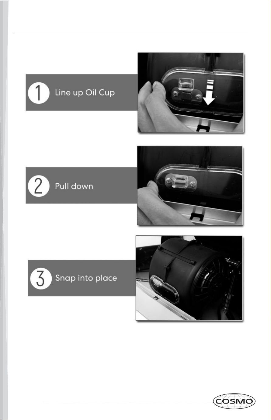
OIL CUP INSTALLATION
16 17
It is recommended that the charcoal filter be replaced every 4-6 months. Charcoal
filter replacements are available for purchase at: www.cosmoappliances.com
Charcoal Filter Kit Part# CFK1-TM
Step 1: Remove the ARC-FLOW Baffle Filters.
Step 2: Locate the motor (pictured below) and align
one of the filters with the right side of the motor.
Step 3: Twist and lock the filter into place.
Step 4: Repeat Steps 2-3 on the left side of the motor.
Step 5: Reinstall the ARC-FLOW Baffle Filters back into place.
NOTE: Chimney vent holes must be open
and visible for the filtered air to
recirculate.
Chimney
vent holes
MOTOR
SCAN QR CODE
FOR INSTALLATION
VIDEO
DUCTLESS CONVERSION
OIL CUP INSTALLATION
18 19
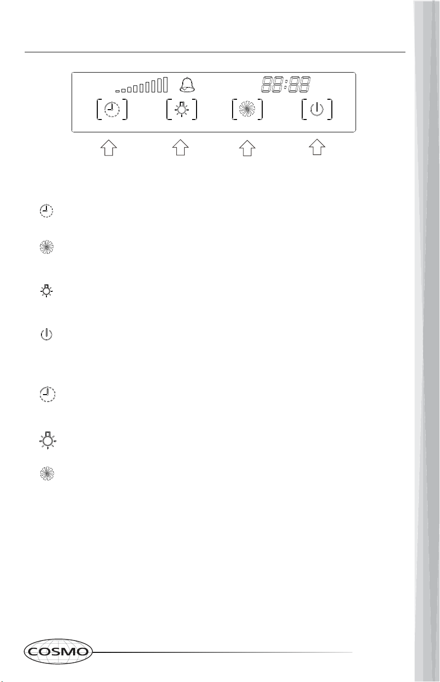
To set the clock: Touch and hold the timer setting
symbol for approximately 3 seconds.
Touch (light button) to set hour.
Touch (Speed button) to set minutes.
Timer setting: Press once to add 1 minute delay auto
shut-off. The maximum is 59 minutes.
Press once for high speed, twice for middle speed, and
three times for low speed, and recycle.
Press to turn the Lights ON or OFF.
When the motor is working, press once to enter into 1
minute delay auto shut-off mode. Press again to turn
off the motor immediately.
TIMER LIGHT SPEED SETTINGS ON/OFF
SOFT TOUCH CONTROLS
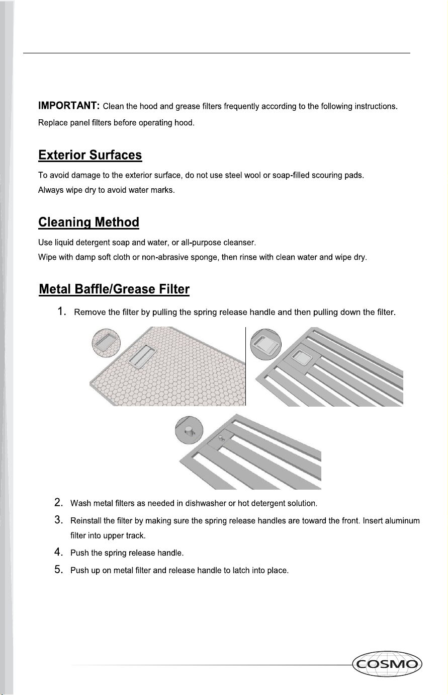
CLEANING
MAINTENANCE
18 19
To set the clock: Touch and hold the timer setting
symbol for approximately 3 seconds.
Touch (light button) to set hour.
Touch (Speed button) to set minutes.
Timer setting: Press once to add 1 minute delay auto
shut-off. The maximum is 59 minutes.
Press once for high speed, twice for middle speed, and
three times for low speed, and recycle.
Press to turn the Lights ON or OFF.
When the motor is working, press once to enter into 1
minute delay auto shut-off mode. Press again to turn
off the motor immediately.
TIMER LIGHT SPEED SETTINGS ON/OFF
SOFT TOUCH CONTROLS
CLEANING
MAINTENANCE
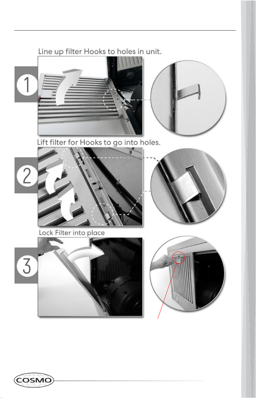
20 21
Push button in and down
PERMANENT FILTERS INSTALLATION
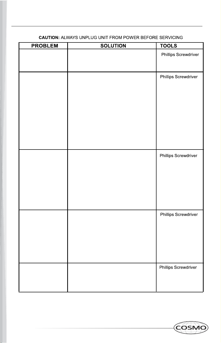
TROUBLESHOOTING
Range Hood does
not turn on
A. Make sure that range hood is plugged
into powered outlet. Test outlet with other de-
vice if not working.
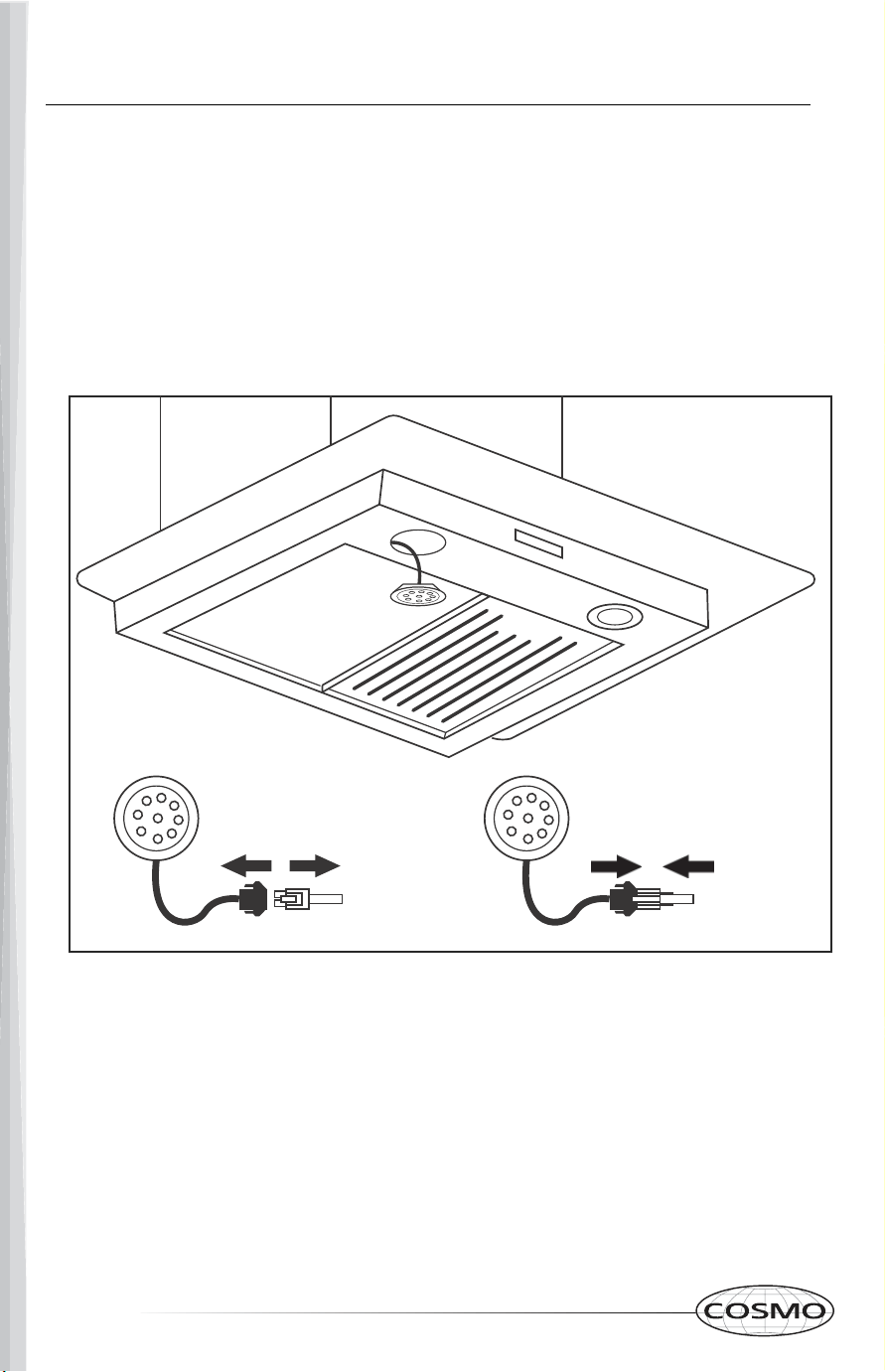
B. Remove baffle filters, reach inside behind
the control panel and locate the wire with
clip. Make sure control panel is securely
plugged in.
C. Check the plastic clip connection coming
out of the motor housing to make sure it's in-
tact.
My range hood is noisy
A. Check inside the range hood for any
loose debris and remove.
If your range hood is still noisy after checking,
please call 1-888-784-3108.
My range hood has
poor performance
My range hood shakes
Light bulbs went out
A. The installation is not secure. Check
again and make sure the installation
hardware is securely mounted.
B. The fan is broken or not balanced.
Re-align or replace fan.
C. The motor is loose. Check and make
sure the motor is solidly mounted to the
unit.
D. Baffle filter is loose and is not installed
correctly. Read page 12 for installation
instructions.
A. The range hood and cooktop are too
far away from each other.
Optimal distance is 24" to 36"
B. There are too many open windows or
doors in the area. Close some doors or
windows.
C. The motor performance has decreased
due to wear. Replace motor.
D. Check and make sure the tape holding
down the damper flaps at the vent hole
are removed before use.
E. The oil cup is full and needs to be
cleaned out.
F. The filters are clogged and need to be
cleaned.
A. Replace with a new LED lamp assembly.
B. Remove baffle filters, reach inside behind
the control panel and locate the wire with clip
behind the light housing. Make sure the light
is securely plugged in.
IF YOU HAVE TRIED ALL SOLUTIONS AND STILL EXPERIENCE
ISSUES, PLEASE CALL SUPPORT: 1-888-784-3108.
20 21
Push button in and down
PERMANENT FILTERS INSTALLATION
TROUBLESHOOTING
Range Hood does
not turn on
A. Make sure that range hood is plugged
into powered outlet. Test outlet with other de-
vice if not working.
B. Remove baffle filters, reach inside behind
the control panel and locate the wire with
clip. Make sure control panel is securely
plugged in.
C. Check the plastic clip connection coming
out of the motor housing to make sure it's in-
tact.
My range hood is noisy
A. Check inside the range hood for any
loose debris and remove.
If your range hood is still noisy after checking,
please call 1-888-784-3108.
My range hood has
poor performance
My range hood shakes
Light bulbs went out
A. The installation is not secure. Check
again and make sure the installation
hardware is securely mounted.
B. The fan is broken or not balanced.
Re-align or replace fan.
C. The motor is loose. Check and make
sure the motor is solidly mounted to the
unit.
D. Baffle filter is loose and is not installed
correctly. Read page 12 for installation
instructions.
A. The range hood and cooktop are too
far away from each other.
Optimal distance is 24" to 36"
B. There are too many open windows or
doors in the area. Close some doors or
windows.
C. The motor performance has decreased
due to wear. Replace motor.
D. Check and make sure the tape holding
down the damper flaps at the vent hole
are removed before use.
E. The oil cup is full and needs to be
cleaned out.
F. The filters are clogged and need to be
cleaned.
A. Replace with a new LED lamp assembly.
B. Remove baffle filters, reach inside behind
the control panel and locate the wire with clip
behind the light housing. Make sure the light
is securely plugged in.
IF YOU HAVE TRIED ALL SOLUTIONS AND STILL EXPERIENCE
ISSUES, PLEASE CALL SUPPORT: 1-888-784-3108.
22 23
NOTES

22 23
NOTES

24 25
24 25