MANUFACTURED BY:
Indoor Cycling Group GmbH
Happurger Str. 86
90482 Nuremberg | Germany
www.indoorcycling.com
Phone: +49(0)911 / 54 44 50
CAUTION!
READ ALL PRECAUTIONS AND INSTRUCTIONS IN THIS MANUAL BEFORE YOU START
USING THIS EQUIPMENT. PLEASE KEEP THIS MANUAL FOR FUTURE REFERENCE.
IMPROPER ASSEMBLY, USE OR MAINTENANCE CAN VOID THE WARRANTY TERMS.
Version 1.0 2017 IC-CYIC2B1-01 Copyright by Indoor Cycling Group GmbH 2017 | www.indoorcycling.com
ENG
IC2
MODEL NO:IC-CYIC2B1-01

Version 1.0 2017 IC-CYIC2B1-01 Copyright by Indoor Cycling Group GmbH 2017 | www.indoorcycling.com
TECHNICAL SPECIFICATIONS:
The CYBEX 500IC Bike is according to EN 957 a Class S product for professional
and / or commercial use. Such training equipment is intended for the use in training areas
of organizations such as tness clubs or sport associations, where access and control is
specially regulated by the person who has the legal responsibility.
WARNING!
The bike is designed to accommodate most users from
150 cm to 205 cm (4’11’’ to 6’ 9’) body height.
TABLE OF CONTENTS
IMPORTANT PRECAUTIONS P.3
GETTING STARTED P.4
HOW TO ASSEMBLE THE INDOOR CYCLE P.5-7
INITIAL INSTALLATION CHECKS P.8-9
HOW TO ADJUST THE INDOOR CYCLE P.10-12
RESISTANCE ADJUSTMENT P.13
HOW TO MOVE THE INDOOR CYCLE P.13
PREVENTIVE MAINTENANCE P.14-18
MAINTENANCE ACTIVITY PLAN P.19
SPARE PARTS P.20
LIMITED WARRANTY P.21-22
FOOT PRINT: 53 X 115 CM / 20.9 X 45.3 INCH
WEIGHT OF BIKE: 48 KG / 106 LBS
MAX SADDLE HEIGHT: 116 CM / 45,7 INCH
MAX HANDLEBAR HEIGHT: 119 CM / 47 INCH
MAX USER WEIGHT: 130 KG / 287 LBS

3
ENG
1. It is the sole responsibility of the owner to
ensure that all users of the indoor cycle are
informed and aware of all warnings
and precautions.
2. Operate and maintain the indoor cycle
only as described in this manual and after
proper assembly and functionality check as
described in this manual.
3. Keep the indoor cycle indoors, away from
moisture and dust. Do not place the indoor
cycle in a garage or covered patio or near
water or pools.
4. Place the indoor cycle on a level surface.
To protect the oor or carpet from damage,
place a mat beneath the indoor cycle.
Make sure that there is adequate room (20
inches/0,5m) around the indoor cycle to
assemble, disassemble and operate it.
5. Regularly inspect and properly tighten all
parts of the indoor cycle as recommended in
this manual. Please replace defective parts
immediately and do not use the Bike until
repair is performed. Only use original parts
from the manufacturer.
6. Children under the age of 14 should
only be allowed use of the indoor cycle
with parental approval and supervision. If
the indoor cycle is not in use, please make
sure the brake resistance is fully engaged
to prevent drive gear components from
movement and to avoid the potential risk of
injury due to improper use.
7. The indoor cycle should not be used by
persons exceeding weight of 287 lbs/130 kg.
8. Always wear appropriate riding gear and
shoes for cycling while operating the indoor
cycle. Do not wear loose clothes or shoes
with loose laces which could become caught
on the indoor cycle.
9. Before using the indoor cycle, make sure
you are familiar with the setup/operation of
the indoor cycle.
10. The indoor cycle does have a direct
driven ywheel (wheel); the pedals will
continue to move along with the ywheel
until the ywheel stops.
11. Always regulate the ywheel resistance
so that your pedalling motion is controlled.
12. Keep your back straight while using the
indoor cycle; do not arch your back.
13. If you feel pain or dizziness while
exercising, stop immediately, rest and cool
down and consult a physician.
14. If replacement parts are needed, use only
manufacturer supplied parts.
IMPORTANT
PRECAUTIONS
WARNING!
To reduce the risk of serious injury, read the following
precautions and information carefully before
operating the indoor cycle.
WARNING!
Before beginning any exercise program, consult
your physician. This is especially important for
persons over the age of 35 or persons with pre-
existing health problems. Read all instructions
before using. Be aware that incorrect or extensive
training may result in serious health injuries.
The manufacturer assumes no responsibility for personal injury or
property damage related by or through the use of this product.
Version 1.0 2017 IC-CYIC2B1-01 Copyright by Indoor Cycling Group GmbH 2017 | www.indoorcycling.com
GETTING STARTED
DEAR CUSTOMER,
Congratulations for selecting the CYBEX 500IC. The CYBEX indoor cycle oers an impressive array
of features designed to enhance cardiovascular tness, tone muscles, and develop endurance.
Whether users are beginners or experienced athletes, the CYBEX 500IC oers workouts that will
help users to reach their individual tness goals.
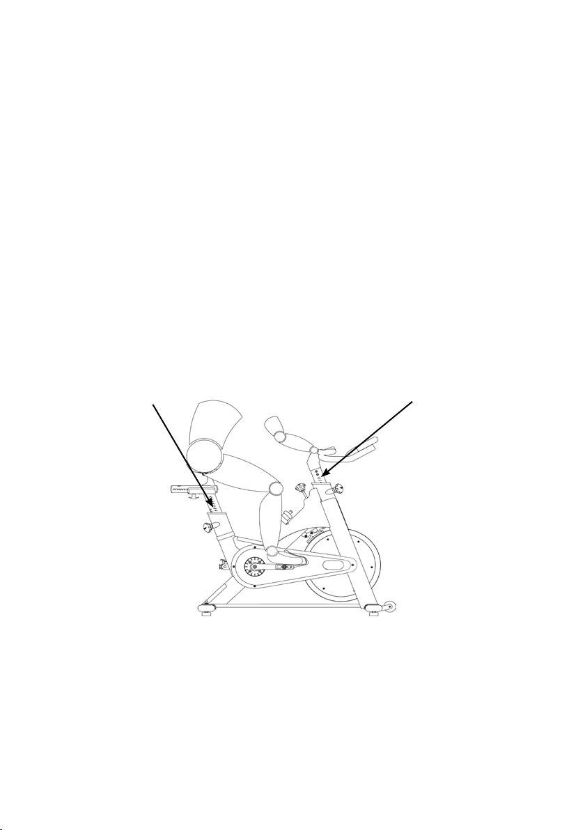
IMPORTANT: Read this manual carefully before assembling or using the indoor cycle. If you have
questions after reading this manual, please contact your local distributor or refer to the website
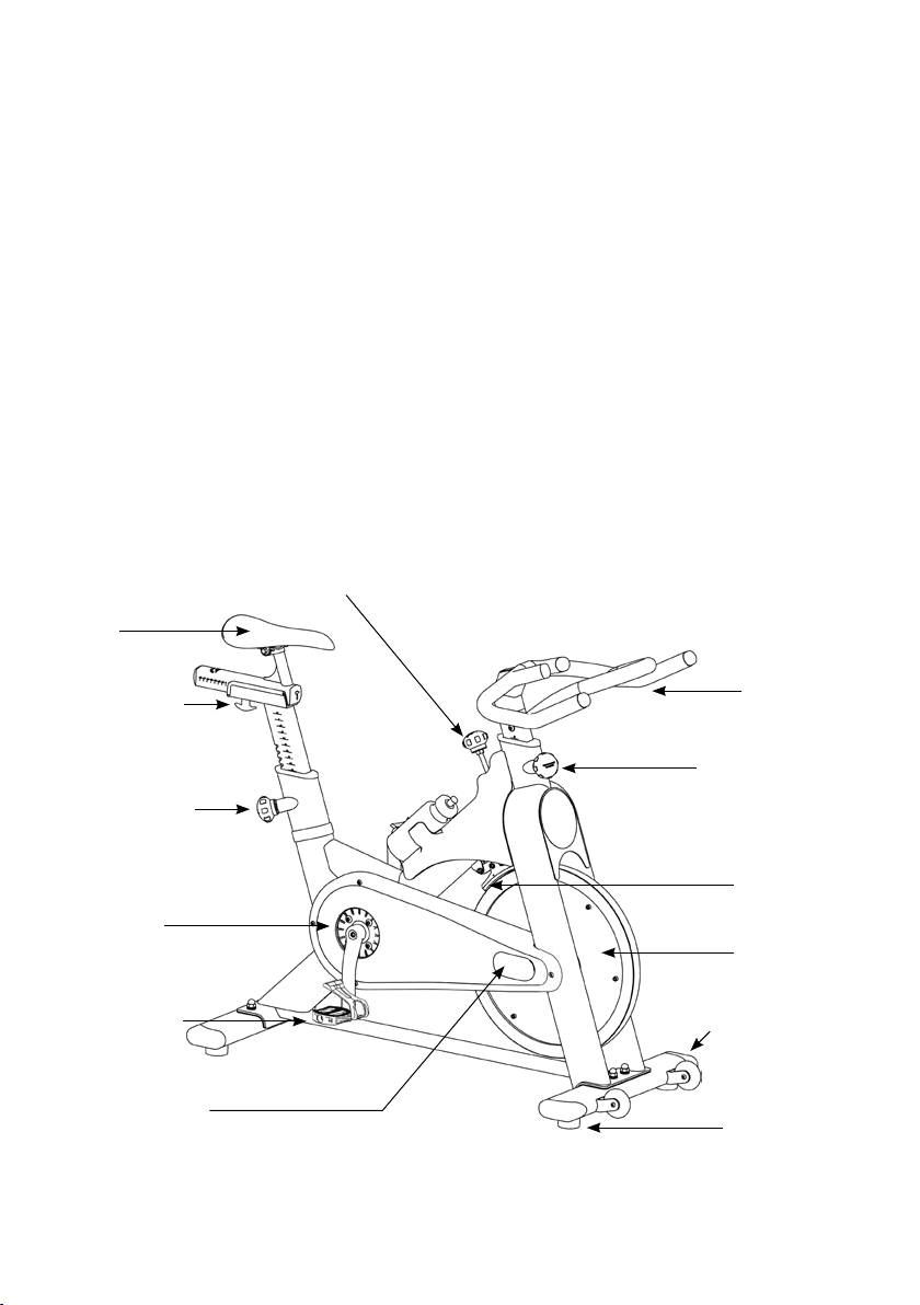
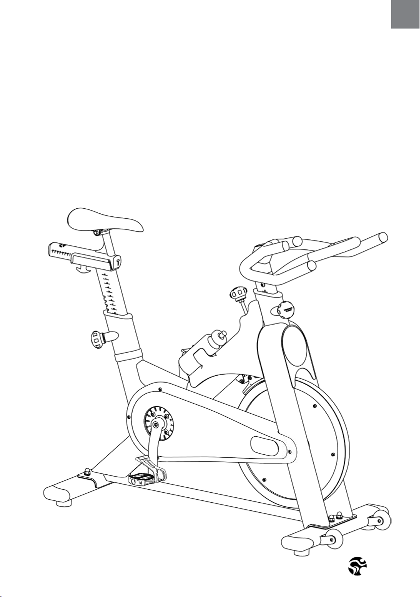
www.indoorcycling.com. Before reading further, please familiarize yourself with the parts that
are labeled in the drawing below.
YOU WILL FIND THE PRODUCTION CODE ON THE LEFT SIDE OF THE CYBEX 500IC WITHIN THE LOWER
RANGE OF THE FRAME. PLEASE REGISTER THESE IN SERVICING AND MAINTENANCE LISTS.
EMERGENCY BRAKE & RESISTANCE KNOB
SADDLE
T- LOCK HANDLE
ADJUSTMENT KNOB
PEDAL /TOE CLIP
CHAIN GUARD
MAINTENANCE COVER
HANDLEBAR
ADJUSTMENT KNOB
BRAKE PAD
FLYWHEEL
TRANSPORT WHEEL
LEVELLING FEET
5
ENG
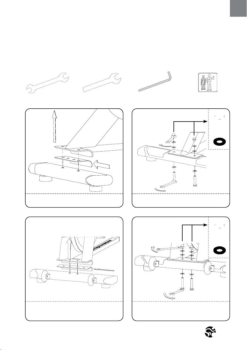
HOW TO ASSEMBLE THE
INDOOR CYCLE
2X 17MM
1X 13MM
15MM
PEDAL WRENCH
1X
5MM
2
PEOPLE
1. 2.
4.3.
ASSURE THAT PLASTIC GASKET IS PLACED BETWEEN
STABILIZER AND FRAME.
ASSURE THAT PLASTIC GASKET IS PLACED BETWEEN
STABILIZER AND FRAME. GASKET SHOULD NOT BE
VISIBLE ONCE ASSEMBLED.
ASSURE THAT BLACK RUBBER WASHER IS PLACED
BETWEEN UPPER FRAME AND BOLT/WASHER.
ASSURE THAT BLACK RUBBER WASHER IS PLACED
BETWEEN UPPER FRAME AND BOLT/WASHER.
7NM
Version 1.0 2017 IC-CYIC2B1-01 Copyright by Indoor Cycling Group GmbH 2017 | www.indoorcycling.com
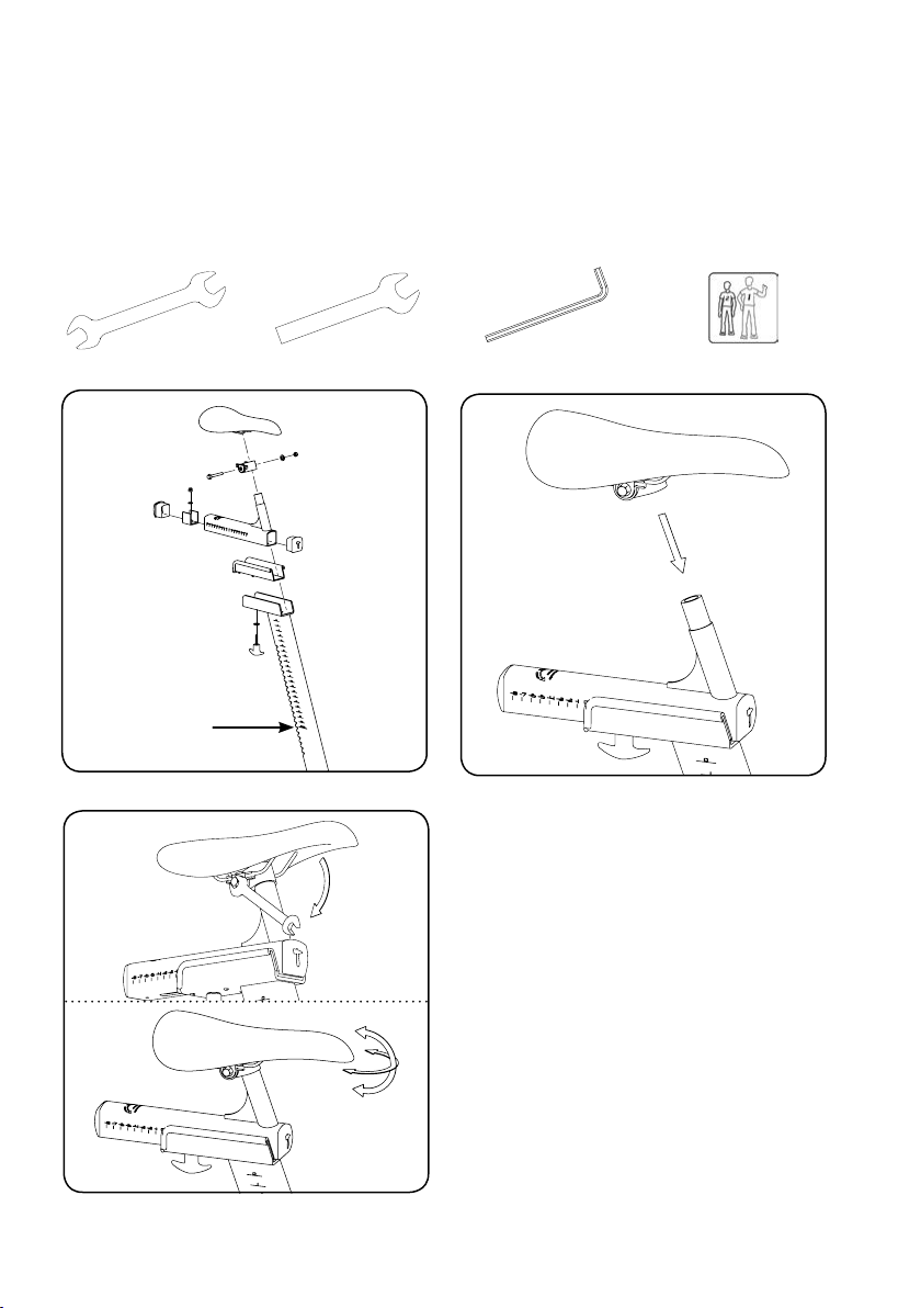
HOW TO ASSEMBLE THE
INDOOR CYCLE
WARNING!
Make sure the seat is xed properly in
a LEVEL HORIZONTAL position and
securely tigthend from both sides!
5. 6.
STOP MARK
2X 17MM
1X 13MM
15MM
PEDAL WRENCH
5MM
2
PEOPLE
1X
7.
25NM
7
ENG
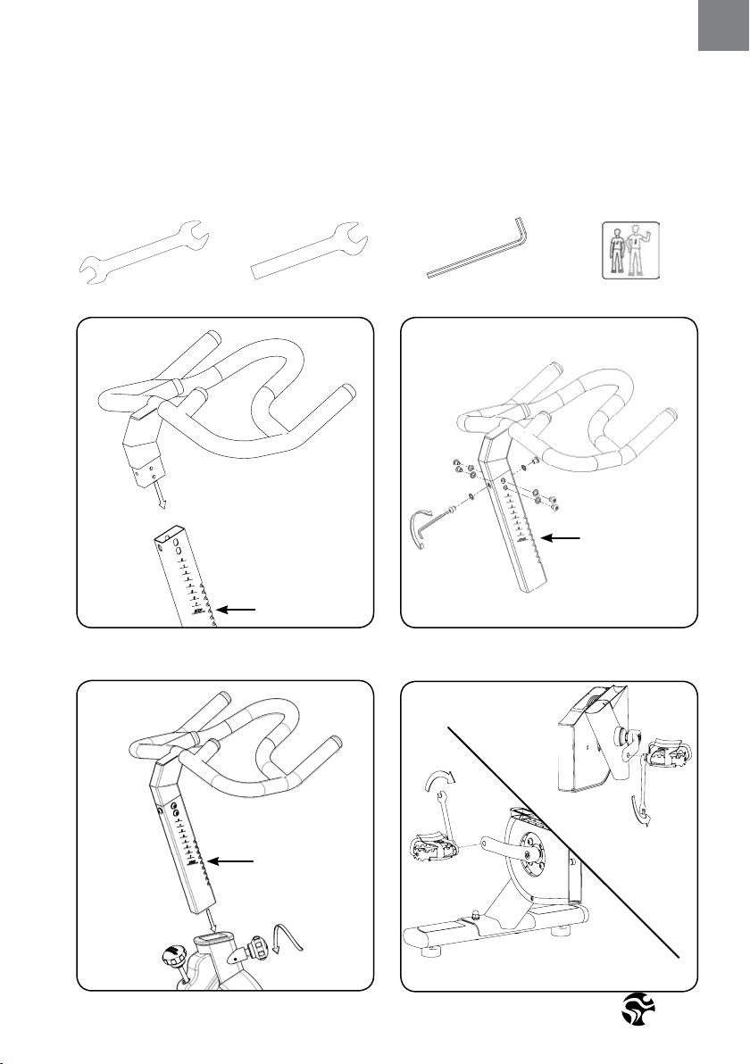
HOW TO ASSEMBLE THE
INDOOR CYCLE
2
PEOPLE
8. 9.
STOP MARK
STOP MARK
STOP MARK
2X 17MM
1X 13MM
15MM
PEDAL WRENCH
1X
5MM
11.
10.
WARNING!
Pedal marked R installed on right crank (clockwise). Pedal marked L installed on left crank (counter-
clockwise) Pedals must be fastened with signicant strength to avoid loosening with use of the CYBEX 500IC.
55NM
18NM

Version 1.0 2017 IC-CYIC2B1-01 Copyright by Indoor Cycling Group GmbH 2017 | www.indoorcycling.com
INITIAL
INSTALLATION CHECKS
The cycle tune-up must be performed at initial installation of the CYBEX 500IC
for optimal performance and longevity. Please read and follow all instructions
below. If the CYBEX 500IC is not installed and tuned as described, components
may wear excessively and the CYBEX 500IC may become damaged. If you have
questions about the installation, please contact [email protected].
Note: Some maintenance procedures require acid-, silicone- and solvent free spray
lubricant (for example BRUNOX), and white lithium grease.
1. Make sure that the CYBEX 500IC is leveled. If the CYBEX 500IC rocks on the oor, turn the
leveling feet underneath the front and/or rear stabilizer until the rocking motion is elimina ted.
2. Verify emergency brake function to assure that emergency brake functions correctly.
3. Brake pad calibration: Turn resistance knob counterclockwise as far as possible (minimum
braking eect), verify that there is a slight separation of the brake pad from ywheel. Brake pad
should barely touch the ywheel when resistance knob is turned counter-clockwise as far as it
can go.
4. Apply spray lubricant to the brake pad using the lubrication holes on the plastic part or the
brake pad and externally on the felt pad. Make sure brake pad is thoroughly soaked from end
to end with lubricant spray. Then, wipe the excess o from the ywheel.
* Best Practice: Use a rellable spray bottle lled with non-aerosol acid-, silicone- and
solvent free spray lubricant purchased by the gallon (3.7 L) at the local hardware store.
5. Apply lithium grease to the threads on the lower end of the brake rod. First, turn the resistance
knob clockwise until it stops. Apply a small amount of white lithium grease to the threads on
the brake rod above the two lock nuts. Then, turn the resistance knob counter-clockwise
until it stops.

9
ENG
INITIAL
INSTALLATION CHECKS
6. Apply lithium grease on the metal threads of all the adjustment knobs.
7. Verify four (4) allen nuts on RS pulley for tightness. If loose, apply LocTite Threadlocker
Blue-243 and retighten.
8. Verify R and L crank arm allen bolts for tightness. If loose, apply LocTite Threadlocker
Blue-243 and retighten.
9. Verify belt tension. Check if belt drive is rmly tightened and does not slip while riding under
resistance load. In case that the belt slips, proceed using the adjustment technique as described
on page (18). Please note that a belt drive gear never shows slack. In case of adjustment do not
apply too much tension.
10. Wipe down bike frame with rag moistened with solvent free spray lubricant
11. Some parts of the CYBEX 500IC may become loose during shipment. Check crank arms,
check all exposed screws, bolts, and nuts, and make sure that they are properly tightened.
CUSTOMER SERVICE
1. Provide basic maintenance instructions to client and direct them to detailed maintenance
instructions (page 14-19 )
2. Sign-o sheet provided to client to conrm explanation of maintenance procedures/manual
and verication of condition of bikes?
Version 1.0 2017 IC-CYIC2B1-01 Copyright by Indoor Cycling Group GmbH 2017 | www.indoorcycling.com
HOW TO ADJUST THE
INDOOR CYCLE
The CYBEX 500IC can be adjusted for maximum comfort and exercise eectiveness. The
instructions below describe one approach to adjusting the CYBEX 500IC to ensure optimal user
comfort and ideal body positioning; you may choose to adjust the CYBEX 500IC cycle dierently.
PEDAL STRAP ADJUSTMENT:
Sit on the saddle and position your feet on the pedals, with the balls of your feet directly above
the spindles of the pedals (see the drawing below). Adjust the pedal straps so the toe clips
(cages) are snug but not too tight. Note: In the case of a bike being tted with combi-pedals, the
pedals feature toe clips on one surface and SPD cleats on the opposite surface. If desired, use the
shoe cleats with cycling shoes instead of the toe clips.
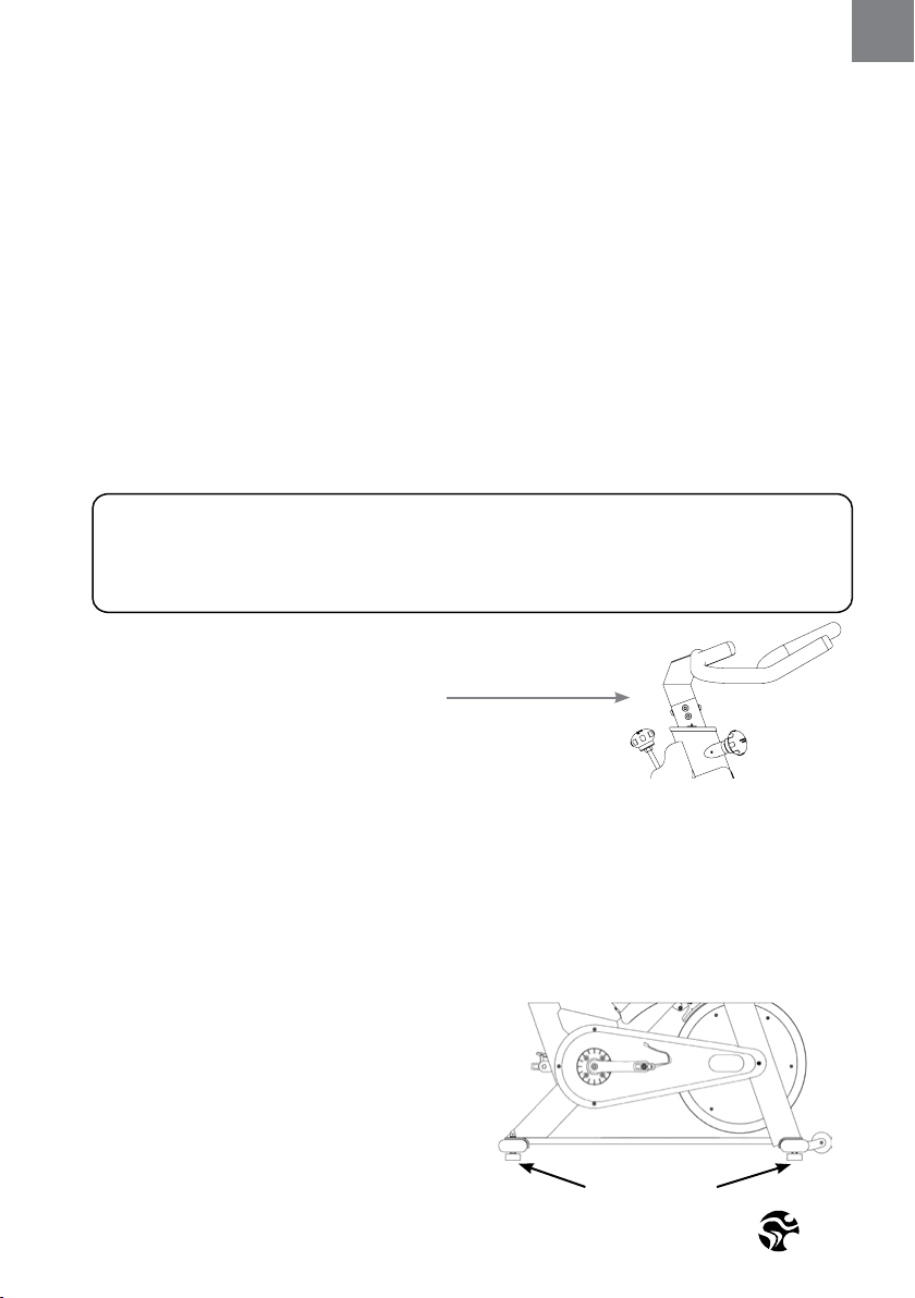
Please do not adjust
handlebar height beyond
the STOP mark on the
stem and ensure the pop
pin is fully engaged
and securely tightened
WARNING!
Please avoid overtightening the pop pin adjustment knob as this may cause damages to the
vertical aluminum stems.
SADDLE HEIGHT ADJUSTMENT:
Sit on the saddle and slowly pedal until the right pedal is in the lowest position. Your knees
should be slightly bent without a dropping of the hips. To avoid hyper extending your knees,
make sure that your legs are not completely straight.
Please do not adjust
saddle height beyond
the STOP mark on the
stem and ensure the pop
pin is fully engaged and
securely tightened
11
ENG
HOW TO ADJUST THE
INDOOR CYCLE
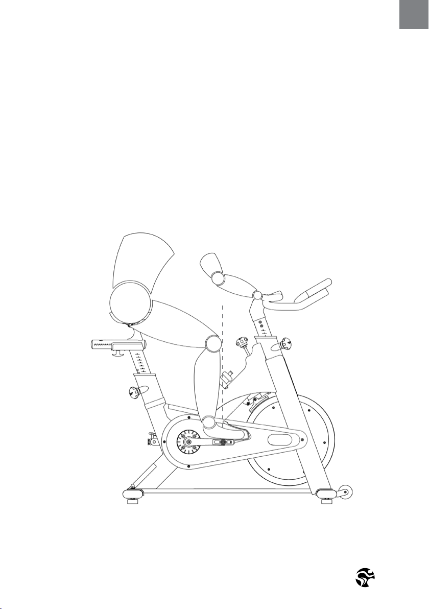
SADDLE HORIZONTAL ADJUSTMENT:
Proper horizontal adjustment of the saddle is very important in avoiding injury to the knees.
Sit on the saddle and move the pedals until the crank arms are in horizontal position.
Using your forward most leg as a marker, your kneecap should be directly above the center of the pedal so that a straight
line is created between knee and center of the pedal (see the dotted line in image below). To adjust the horizontal po-
sition of the saddle, rst dismount the CYBEX 500IC. Next, loosen the rear adjustment knob, slide the saddle forward or
backward as required, and then retighten the knob.
Version 1.0 2017 IC-CYIC2B1-01 Copyright by Indoor Cycling Group GmbH 2017 | www.indoorcycling.com
HOW TO ADJUST THE
INDOOR CYCLE
If your CYBEX 500IC is equipped with a regular 2 way handlebar. If the handlebar is too close
to the saddle, your breathing may feel restricted; if the handlebar is too far from the saddle,
you may experience back discomfort. To adjust the horizontal position to the handlebar, rst
dismount the CYBEX 500IC.
Check for proper handlebar position by positioning your elbow so that it is touching the front tip of the saddle at a
90 degree angle and checking that the ngertip of your middle nger is touching the handlebar at the mid-point. If it
is not as described then loosen the fore-aft T-lock handle and slide the saddle slightly forward or backward until your
middle nger is touching the handlebar at the mid-point, and then retighten the handle. Changing your hand position
can change the angle of your back, neck, and arms. To minimize the stress on your muscles during your workouts, change
your hand position frequently.
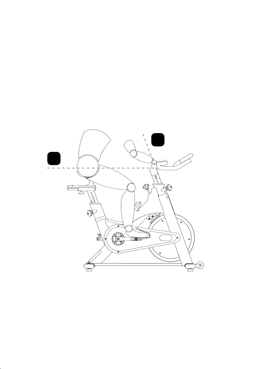
HANDLEBAR ADJUSTMENT:
Begin with the top of the handlebar at relatively the same height or just slightly higher than
the top of the saddle (dotted horizontal line A in the drawing above) and at a neutral fore/
aft position (see dotted vertical line B in drawing above). If your knees touch the handle-
bars or if you experience back discomfort while pedalling for extended periods of time, the
height of the handlebars can be adjusted. First, dismount the CYBEX 500IC. Next, turn the front
adjustment knob counter clockwise, slide the handlebar post up or down, and then re-tighten
the adjustment knob.
A.
B.
13
ENG
HOW TO OPERATE THE
INDOOR CYCLE
RESISTANCE ADJUSTMENT:
The preferred level of diculty in pedalling (resistance) can be regulated in ne increments by
use of the resistance knob. To increase the resistance, turn the resistance knob clockwise. To
decrease the resistance, turn the knob counter clockwise.
IMPORTANT: To stop the ywheel (wheel) while pedalling, push down on the red brake knob. The ywheel should
quickly come to a complete stop. Please make sure your shoes are xed into the toe clip or in case cycling shoes are
used your shoe cleat is connected to the pedal binding while riding.
HOW TO MOVE THE CYBEX 500IC:
Due to the weight of the CYBEX 500IC, it is recommended that two persons move it. While one
person lifts the back of the CYBEX 500IC, the second person rmly holds the handlebar and
tips the CYBEX 500IC forward until it rolls on the wheels. Carefully move the indoor cycle to the
desired location and then lower it. CAUTION: To reduce the risk of injury,
use extreme caution while moving the indoor cycle. Do not attempt to move it over
uneven surfaces and make sure a safety space of min 20 inch to the nearest
equipment is redeemed.
If the CYBEX 500IC rocks on the oor after being set
down, turn the levelling feet (see diagram) underneath
the front or rear stabilizer until the rocking motion is
eliminated.
Important: Please do not unscrew the levelling feet
more then ½ inch!
LEVELLING FEET
The CYBEX 500IC does not have a free moving flywheel (wheel); the pedals will continue to move together with the
flywheel until the flywheel stops. Reducing speed in a controlled manner is required. To stop the flywheel immediately,
push down the red break knob. Always pedal in a controlled manner and adjust your
desired cadence according to your own abilities.
PUSH THE RED KNOB DOWN = EMERGENCY STOP
RED RESISTANCE KNOB (TURN)
EMERGENCY BRAKE (PUSH)

Version 1.0 2017 IC-CYIC2B1-01 Copyright by Indoor Cycling Group GmbH 2017 | www.indoorcycling.com
PREVENTIVE
MAINTENANCE
WARNING!
REGULAR MAINTENANCE MUST BE PERFORMED ON THE CYBEX 500IC FOR OPTIMAL
PERFORMANCE AND LONGEVITY.
Please read and follow all instructions below. If the CYBEX 500IC is not maintained as described,
components may wear excessively and the CYBEX 500IC may become damaged. Improper
maintenance will void the warranty terms. If you have questions about maintenance, contact
your local distributor or refer to www.indoorcycling.com
NOTE: MANY MAINTENANCE PROCEDURES REQUIRE LUBRICANT SPRAY.
MANUFACTURER RECOMMENDS FOR EXAMPLE BRUNOX OR A SIMILAR
SOLVENT- AND ACID FREE LUBRICANT.
DAILY MAINTENANCE:
1. Make sure that the CYBEX 500IC is leveled. If the CYBEX 500IC rocks on your oor, turn the
levelling feet underneath the front or rear stabilizer until the rocking motion is eliminated (see
HOW TO MOVE THE CYBEX 500IC on page 13).
2. After each user nishes exercising, the CYBEX 500IC should be disinfected and cleaned to
maintain a hygienic environment. First, apply a disinfectant spray to the handlebars and the
saddle. Using a lint-free cloth, dry the handlebars and the saddle. Next, apply a small amount
of disinfectant to a lint-free cloth and clean the adjustment knobs and the
adjustment handles. Avoid using strong detergents on the CYBEX 500IC frame.
WEEKLY MAINTENANCE:
1. Apply a small amount of the lubrication spray to a lint-free cloth, and thoroughly clean the
frame, the handlebar slider and seat sliders the ywheel and the plastic parts of the
CYBEX 500IC.
2. For optimal performance of the resistance
system, and to minimize wear on the brake
pad, the acid-, silicone- and solvent free spray
lubricant should be applied to the brake pad
using the lubrication holes on the plastic
part of the brake pad. If fuzz or lint appears
on the brake pad, the brake pad has become
too dry-lubricant spray should be applied
more frequently. Make sure brake pad is
thoroughly soaked from end to end with
lubricant spray. Then, wipe the excess o.
15
ENG
PREVENTIVE
MAINTENANCE
BI-WEEKLY MAINTENANCE:
1. The CYBEX 500IC should not be used if
the emergency brake system is not working
properly. While sitting on the saddle and
pedalling, test the brake by pushing down
the brake knob. The ywheel should come to
a quick and complete stop.
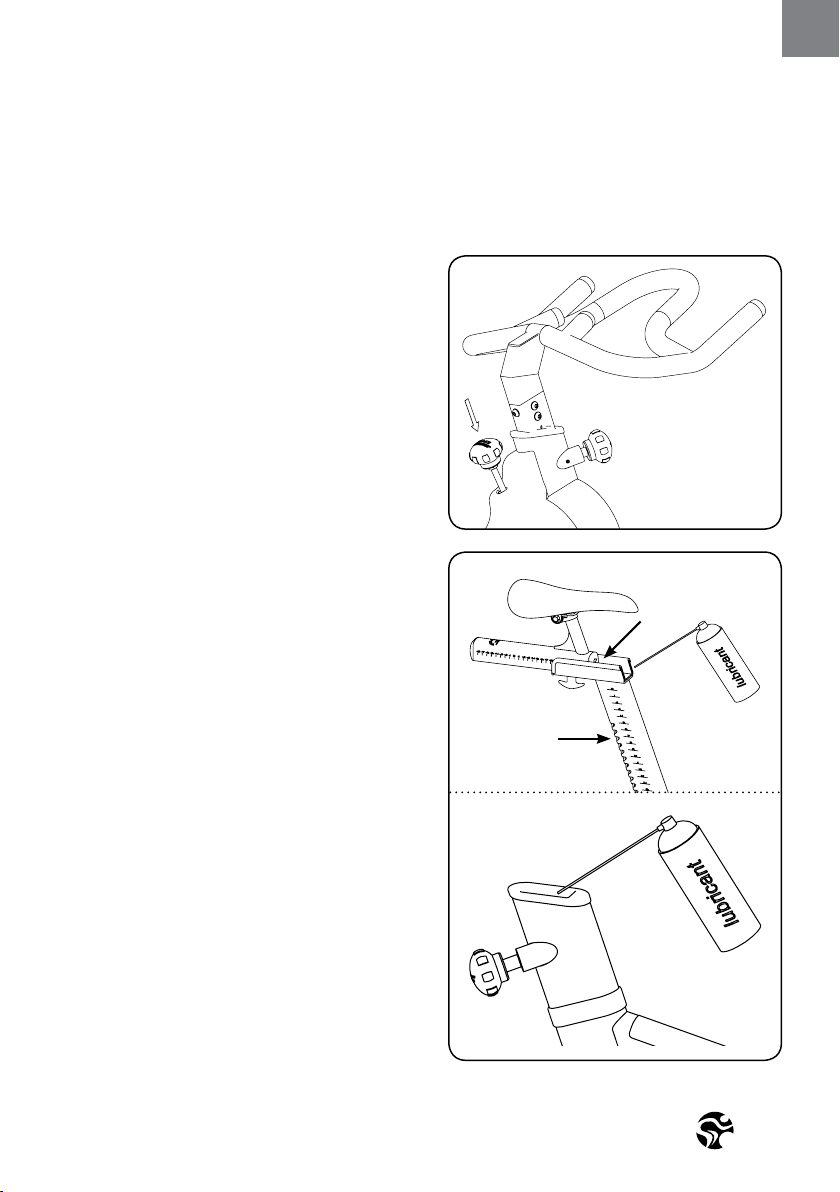
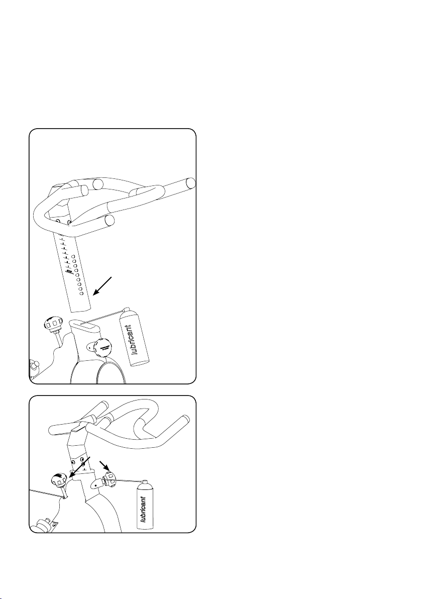
2. To maintain the easy adjustability of
the saddle post, the saddle post should
be cleaned and lubricated. Turn the rear
adjustment knob counter clockwise and slide
the saddle post out of the frame. Apply a
small amount of lubricant spray to a lint-free
cloth, and clean the saddle post (A). Next,
apply a small amount of lubricant spray
inside of the rear frame sleeve. Then, reinsert
the saddle post into the frame and adjust it to
the desired height.
Next, loosen the rear lock handle and slide the saddle
carriage as far backward as possible. Apply a small amount
of lubricant spray to a lint-free cloth, and clean the top of
the saddle slide (B). Then, slide the saddle carriage as far
forward as possible and clean the top of the saddle slide.
Finally, adjust the saddle to the desired position.
A
B
1.
2.
Version 1.0 2017 IC-CYIC2B1-01 Copyright by Indoor Cycling Group GmbH 2017 | www.indoorcycling.com
PREVENTIVE
MAINTENANCE
3. To maintain the easy adjustability of the
handlebar post, the handlebar post should
be cleaned and lubricated. First, turn the
front adjustment knob counter clockwise and
slide the handlebar post out of the frame.
Apply a small amount of lubricant spray to a
lint-free cloth, and clean the handlebar post
(A). Next, apply a small amount of lubricant
spray inside of the front frame sleeve.
Then, reinsert the handlebar post into the frame
and adjust it to the desired height.
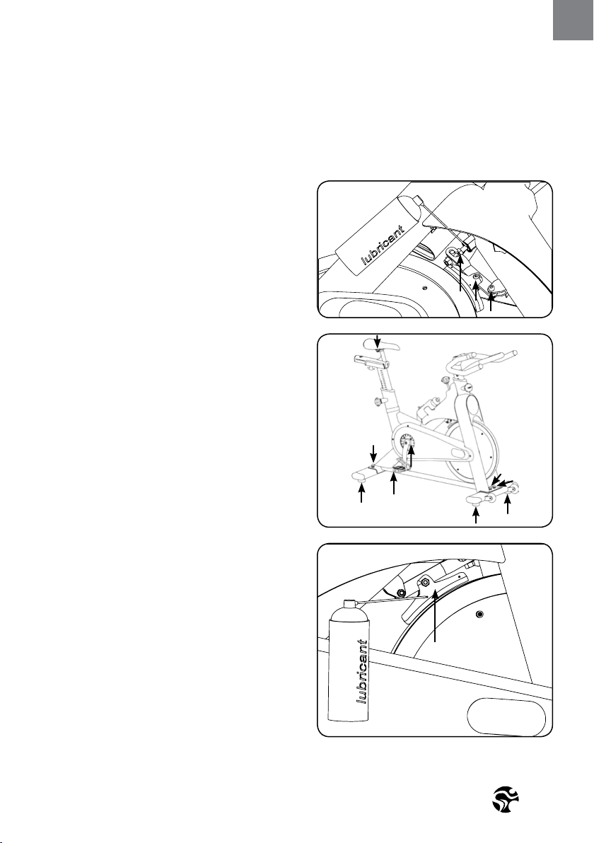
MONTHLY MAINTENANCE:
1. To maintain the smooth function of the
adjustment knobs controlling the handlebar
and saddle, the metal threads on the
adjustment knobs (A) must be lubricated.
1.
A
A
3.
17
ENG
PREVENTIVE
MAINTENANCE
2. To maintain the easy adjustability of the
resistance system, the screw threads on the
lower end of the brake rod should be lubrica-
ted. First, turn the resistance knob clockwise
until it stops. Next, look under the right or
left side of the frame and locate the brake
rod (C). Apply a small amount of synthetic
grease (white lithium grease) to the thread on
the brake rod. Then, turn the resistance knob
counter-clockwise until it stops.
3. Some parts of the CYBEX 500IC may
become loose as a result of repeated use.
Check pedals, toe clips, and pedal straps, and
make sure that they are properly tightened.
Next, check all exposed screws, bolts, and
nuts, and make sure that they are properly
tightened. Finally, check the saddle to make
sure that it is not lose damaged.
4. The brake pad will become worn as a
result of repeated use. The CYBEX 500IC
should not be used if the emergency braking
system is not working properly (see page
13)! Should you feel that the resistance
system’s functions are decient, it is essential
to ne-tune the resistance system before
the bike is used again! Please check the
setting of the brake system as follows:
First turn the resistance regulator on the
brake system as far as it will go to the left
(minimum braking eect). If the setting is
correct, the brake pads should be ush with
the ywheel and barely touching so that it’s
possible to cycle with a hardly noticeable
amount of resistance. The brake pad can
be adjusted using a 10 mm wrench. Next,
check the brake pad for signs of wear. If the
brake pad does show signs of excessive
wear, thoroughly soak the brake pad with
lubricant spray using the 2 lubrication
holes (B), and then wipe the excess o.
C
2.
3.
4.
B
Version 1.0 2017 IC-CYIC2B1-01 Copyright by Indoor Cycling Group GmbH 2017 | www.indoorcycling.com
PREVENTIVE
MAINTENANCE
GRAPHICS ARE THE RIGHT SIDE
OF THE BIKE (RIDING POSITION)
D
D
B
C
C
A
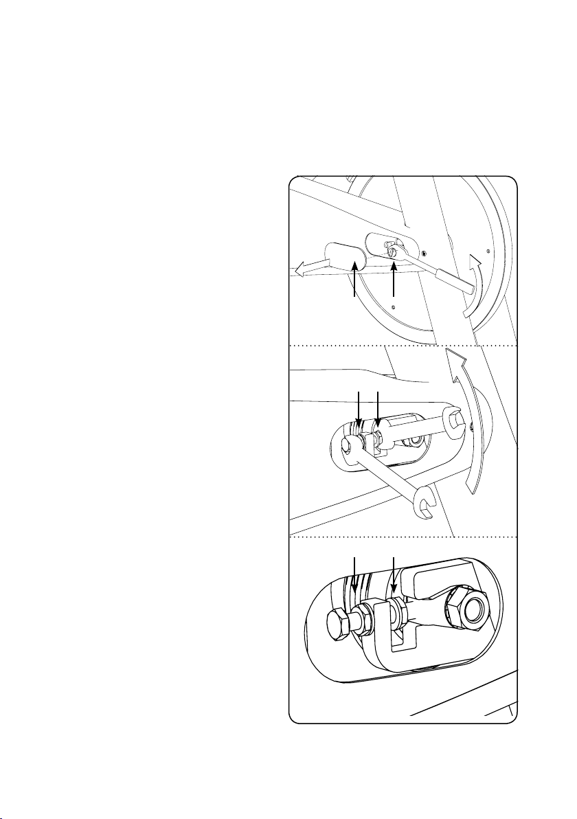
5. BELT DRIVE
Important: A loose belt as well as an
overtightened belt may cause injury of
the rider or damage to the drive system.
Checking belt tension: To check for a loose
belt, sit on the saddle, place your feet on the
pedals, move the pedals until the crank arms
are horizontal. Next, pull up the emergency
brake handle and hold it. Then, stand on the
pedals and rock forward and backward. There
should be no play or slip in the drive train.
If there is slip or play in the drive train, this
indicates that the belt is too loose.
Correct a slipping belt drive train: To adjust the belt,
pull o the right and the left maintenance covers (A).
Loosen the axle nut (B) on both ends of the ywheel
axle by two full turns. Loosen the inner adjustment nut
(D) facing the ywheel axle on each side of the ywheel.
Next, losen the lock nut (C).
Then, turn both (right and left sides) of the inner
adjustment nuts (D) on the intside of the ywheel
bracket ¼ of a turn at a time (upward on the R side and
downward on L side) until the belt is properly adjusted.
Make sure to turn both adjustment nuts exactly the
same amount to avoid misalignment of the ywheel.
Re-check if the amount of play or slip in the drive train
has disappeared.
Finally, retighten the two outer lock nuts (C) to secure the
new adjustment and retigthen the two axle nuts (B). At
last reattach the maintenance covers (A).
Check if belt drive is rmly tighten and does not slip
while riding under resistance load. In case that the belt
slips, proceed using the same technique as described
above. Please note that a belt drive gear never
shows slack. In case of adjustment do not apply
too much tension.
The manufacturer recommends using an ultrasonic
voltage meter adhering to a natural frequency of the belt
of 103 Hz ± 3 Hz. Ball bearing damage due to incorrect
belt tension is excluded from warranty.
5.
19
ENG
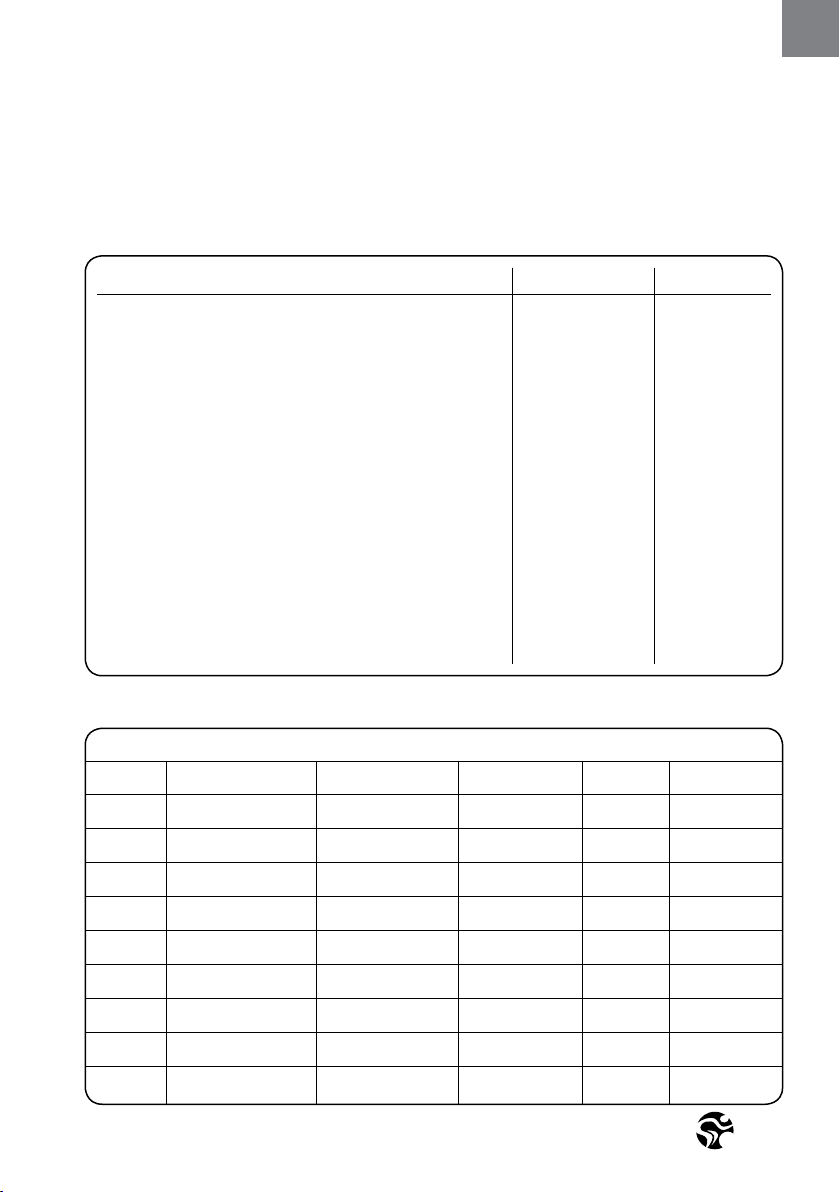
MAINTENANCE ACTIVITY
REQUIRED SCHEDULE
EXAMPLES OF MAINTENANCE PLAN CHARTS FOR IN HOUSE SERVICE TECHNICIANS:
ACTIVITY ROTATION DETAILS
FEET LEVELLING, DISINFECTION
& CLEANING OF THE BIKE DAILY P 14
SERVICING BRAKE PADS, DETAILED
CLEANING OF THE ENTIRE BIKE WEEKLY P 14
CHECK EMERGENCY BRAKE FUNCTION BI-WEEKLY P 15
CLEAN AND LUBRICATE SADDLE
& HANDLEBAR SLIDERS / POSTS BI-WEEKLY P 15+16
CHECK ADJUSTMENT KNOBS MONTHLY P 16
CHECK BRAKE PAD FOR SIGNS OF WEAR MONTHLY P 17
CHECK BRAKE SYSTEM, LUBRICATE MONTHLY P 17
CHECK PEDALS, TOE CLIP & STRAPS MONTHLY P17
FOR SIGNS OF WEAR
CHECK ALL CONNECTIONS AND FIXINGS MONTHLY P17
CHECK BELT DRIVE TRAIN MOTHLY P18
WEEKLY MAINTENANCE CHECKLIST
BIKE NO. PRODUCTION CODE OBSERVATIONS ACTION TAKEN RESULT NAME/DATE
Version 1.0 2017 IC-CYIC2B1-01 Copyright by Indoor Cycling Group GmbH 2017 | www.indoorcycling.com
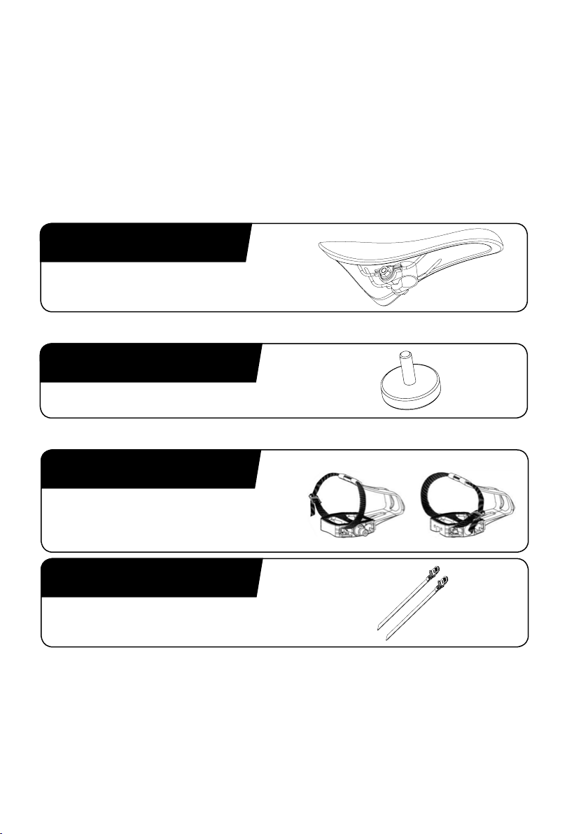
120-01-00015-02
SPORT SADDLE
BLACK & RED INCL. SADDLE CLAMP
SPARE PARTS
Due to revisions, spare part order no. and specications may be subject to change.
For further information please contact your local distributor or visit www.indoorcycling.com.
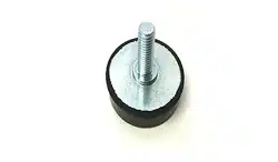
900-10-00003-01
LEVELING FEET, RUBBER 75° SHORE
150-01-00005-03
150-03-00048-01
COMBI PEDAL SET,
SPD COMPATIBLE
TOE STRAP SET
21
ENG
WARRANTY
Indoor Cycling Group GmbH warrants that all new equipment will be free of manufacturing
defects in workmanship and materials, becoming eective on the date of original
installation. Parts repaired or replaced under the terms of this warranty will be warrantedfor
the remainder of the original warranty period only. Warranty may vary by region or country.
Please contact www.indoorcycling.com.
Defects caused by inappropriate use or handling of the product may cause
denegation of the manufacturers warranty.

Version 1.0 2017 IC-CYIC2B1-01 Copyright by Indoor Cycling Group GmbH 2017 | www.indoorcycling.com
WARRANTY
10 YEARS WARRANTY: FRAME CONSTRUCTION AND WELDING
3 YEARS WARRANTY HANDLEBAR AND SADDLE ASSEMBLY, BRAKE SYSTEM
(EXCLUDING BRAKE PAD), LEVER HANDLES AND
KNOBS, CRANKS, BELT DRIVE SYSTEM, BOTTOM BRACKET
ASSEMBLY, FLYWHEEL AND HUB ASSEMBLY,
POWDER COATING OF FRAME PARTS.
2 YEARS WARRANTY : PEDALS, INSERT SLEEVES FOR HANDLE BAR
AND SADDLE POST, LEVELING FEET.
1 YEARS WARRANTY: SADDLE CONSTRUCTION
THE FOLLOWING WEAR ITEMS ARE EXCLUDED FROM WARRANTY:
Pedal straps, pedal binding system, water bottle holder.

23
ENG
NOTES

Version 1.0 2017 IC-CYIC2B1-01 Copyright by Indoor Cycling Group GmbH 2017 | www.indoorcycling.com
Manufactured by: Indoor Cycling Group® GmbH
Happurger Str. 86 90482 Nuremberg Germany
EMAIL: [email protected]OM
WEBSITE: WWW.INDOORCYCLING.COM
© 2017 Indoor Cycling Group
CAUTION.
READ ALL PRECAUTIONS AND INSTRUCTIONS IN THIS MANUAL
BEFORE YOU BEGIN USING THIS EQUIPMENT. PLEASE KEEP
THIS MANUAL FOR FUTURE REFERENCE. IMPROPER ASSEMBLY,
SET UP, USE OR MAINTENANCE MAY VOID THE WARRANTY.