Loading ...
Loading ...
Loading ...
The hood placed above an induction hob can cause condensation, this is a normal phenomenon and not due to malfunctioning of the
product.
For an easy access, it is advisable to move possible furniture under the installation area.
The hood is equipped with all the necessary fastenings for its installation, which are suitable for most surfaces. Verify that the installation
surface is strong.
Installation must be carried out by qualified installers according to present regulations.
The equipment (Fig.1 ) is made of the following items:
1. Telescopic inside structure (Fig. 1-1)
2. Telescopic external chimney (Fig. 1-2)
3. Cooker hood module (Fig. 1-3)
4. Filter support bracket (Fig. 1-4).
INSTALLATION OF THE STRUCTURE TO THE CEILING (Fig. 2)
Uninstall the hood as shown in the sequences 3A, 3B (also disconnect the spotlights and controls connections), 3C, 3D
Adjust the height (A) of the structure of the hood making a difference between the ceiling and the 65 cm of the cooking surface, bearing
in mind that the suction surface stick out 2 cm from quota A
DIRECT FASTENING TO THE CEILING
Fasten the hood with the plugs supplied (Fig.5). Install the duct out pipe (Fig.6). Connect the unit electrically.
Reinstall the hood by following steps 3 (A, B, C, D) in reverse order as per (Fig.7)
FASTENING WITH FALSE CEILING
Fasten the hood with the plugs supplied (Fig.5). Install the duct out pipe (Fig.8).
Connect the chimney fastening brackets A to the hood, bearing in mind that the false ceiling can be from 170 to 250 mm far from the
ceiling. Connect the duct out pipe till the drain. Connect the unit electrically.
Install the false ceiling as shown in (Fig. 9). Reinstall the hood by following steps 3 (A, B, C, D) in reverse order as per (Fig.7).
ELECTRICAL CONNECTION
This equipment must be connected to a grounding plant.
Two types of electrical connection can be used:
1. Using a standard plug to be connected to the power cable and inserted in a mains socket which must be accessible (so that the
plug can be disconnected when servicing is carried out). Make sure that the plug is accessible also after the complete installation
of the equipment.
2. By means of a fixed mains connection, fitting a bipolar switch, which ensures the disconnection, with an opening distance of the
contacts allowing a complete disconnection on the conditions of the overvoltage III category, according to installation regulations.
The ground connection (yellow-green wire) must not be interrupted.
Refer to the plate inside the hood for the mains voltage and frequency ratings.
If the power cable is damaged, it must be replaced by the manufacturer or by its service agent or a qualified person in order to avoid any
risk.
OPERATION
The hood is supplied with a multispeed motor.
The hood should be run at low speed under normal conditions and at higher speeds only when there is a heavy build-up of fumes or
odours.
Ideally, the hood should be switched on as soon as cooking is started and then kept on until all odours have been eliminated.
The hood is supplied with a multispeed motor.
The hood should be run at low speed under normal conditions and at higher speeds only when there is a heavy build-up of fumes or
odours. Ideally, the hood should be switched on as soon as cooking is started and then kept on until all odours have been eliminated.
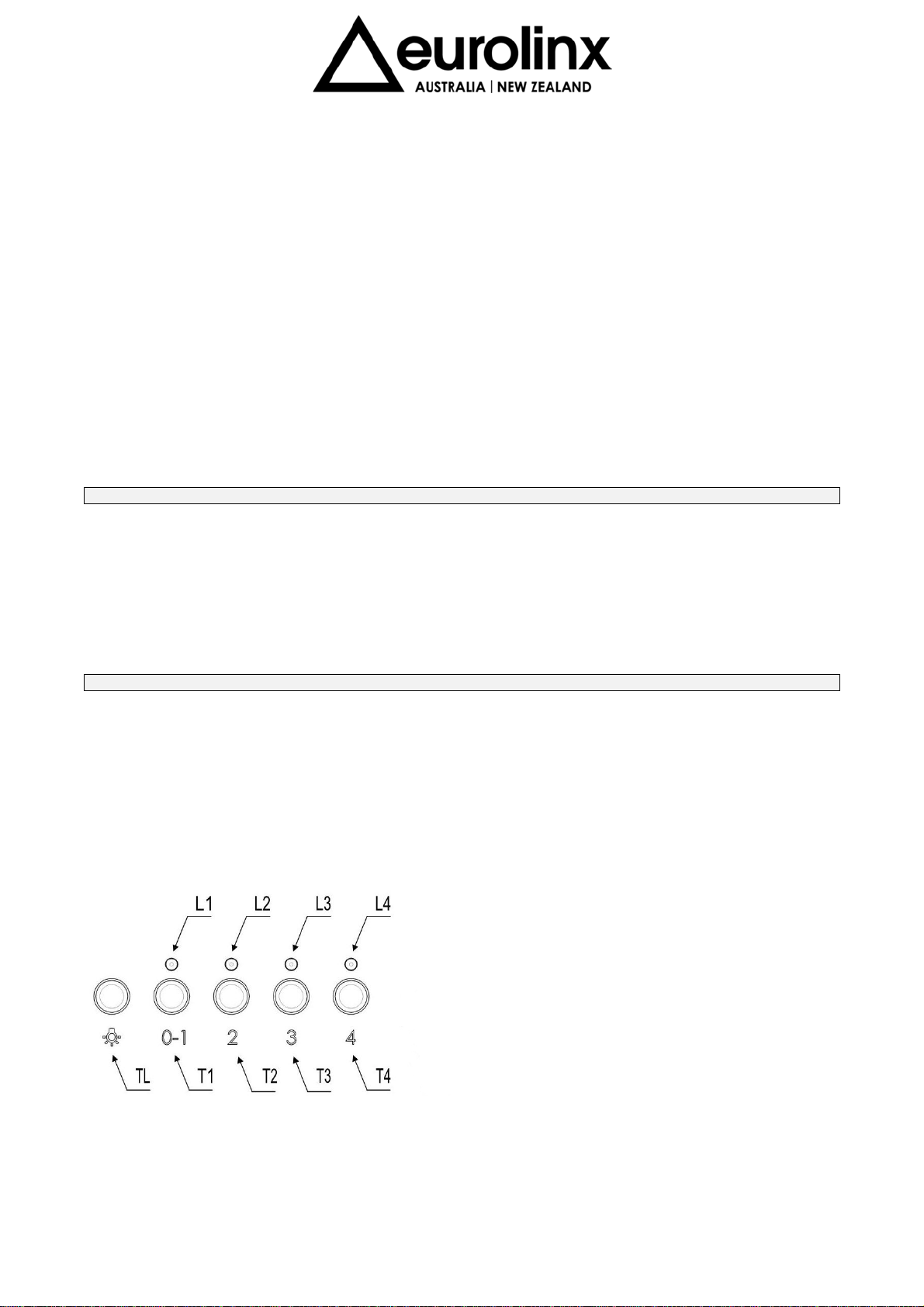
The controls consist of these commands.
Press TL to turn on the light, press T1 to swich on the hood at first speed and to switch off the aspirator, press T2-T3-T4 to select
functioning speeds.
By pressing of the command T1 the motor starts running at the 1
st
speed. The commands T2-T3-T4 switch the motor on respectively at
the 2
nd
, 3
rd
and 4
th
speed.
In order to switch the motor off press T1 once if set at the 1
st
speed, twice if set at the 2
nd
, 3
rd
and 4
th
speed.
The luminous led L1, L2, L3, L4 mean the planned speed.
Self switching off
Turn on the cooker hood at the wanted speed in order to activate the self-switching off, then keep pressed the button “T1” for a few
seconds, until all the led start blinking. Pressing one of the buttons (T1, T2, T3, T4) it is possible to program the self-switching off time,
which is different according to the pressed button (T1= 5 minutes, T2=10 minutes, T3=15 minutes, T4=20 minutes). During the switch-off
time, the set speed can be changed. If you select the maximum speed, after 5 minutes the extraction fan switches to the 3rd speed and
will automatically turn off at such speed. When the option of the self switching off time corresponds to the speed previously programmed
the speed led blinks; when the option is different the speed led is fixed.
Loading ...
Loading ...
Loading ...