Mii
Owner’s manual
12S012720BB
Inglés
12S012720BB (08.20)
SEAT Mii Inglés (08.20)

SEAT S.A. is permanently concerned about continuous development of its types and models. For this reason we ask you to understand,
that at any given time, changes regarding shape, equipment and technique may take place on the car delivered. For this reason no
right at all may derive based on the data, drawings and descriptions in this current handbook.
All texts, illustrations and standards in this handbook are based on the status of information at the time of printing. Except for error or
omission, the information included in the current handbook is valid as of the date of closing print.
Re-printing, copying or translating, whether total or partial is not allowed unless SEAT allows it in written form.
SEAT reserves all rights in accordance with the “Copyright” Act.
All rights on changes are reserved.
❀
This paper has been manufactured using bleached non-chlorine cellulose.
© SEAT S.A. - Reprint: 15.08.20
Vehicle identification data
Model:
Vehicle Registration:
Vehicle identification
number:
Date of vehicle registration
or vehicle delivery:
SEAT Official Service:
Service advisor:
Telephone:
Confirmation of receipt of documentation
and vehicle keys
The following items were delivered
with the vehicle:
YES NO
On-board documentation
First key
Second key
Correct working order of all keys was
checked
Location:
Date:
Signature of owner:

Introduction
Thank you f
or your trust choosing a SEAT v
e-
hicl
e.
With your new SEAT, you will be able to enjoy
a vehicle with state-of-the-art technology
and top quality features.
We recommend reading this Instruction Man-
ual carefully to learn more about your vehicle
so you can enjoy all its benefits in your daily
driving.
Information about handling is complemented
with instructions regarding the operation and
maintenance of the vehicle in order to ensure
its safety and maintain its value. Moreover, we
want to give you valuable advice and tips to
drive your vehicle efficiently and respecting
the environment.
We wish you safe and enjoyable motoring.
SEAT, S.A.
WARNING
Read and always observe safety infor-
mation concerning the passenger's
front airbag
›
››
page 28, Fitting and us-
ing child seats.
About this manual
This manual describes the f
eat
ur
es of the ve-
hicle at the time of drafting this text. Some of
the features described below will be intro-
duced in the future or will only be available in
certain markets.
Some of the features described here are
not included in all the types or variations
of the model and they can be varied or
modified based on technical or marketing
requirements without it being considered
misleading advertising.
Some details on the drawings may vary from
its vehicle and must be interpreted as a
standard representation.
The direction indicators (left, right, forwards,
backwards) in this manual refer to the travel
direction of the vehicle unless otherwise sta-
ted.
The audiovisual material is only meant to
help the users better understand some fea-
tures of the car. It is not a replacement for the
instruction manual. Access the instruction
manual to see the complete information and
warnings.
The features marked with an asterisk
are included by default only in certain
versions of the model, supplied as op-
tional only for certain versions or only of-
fered in certain countries.
Trademarks are marked with ®. The ab-
sence of this symbol does not guarantee
that the term is not a trademark.
It indicates that the section continues on
the next page.
You can access the information in this manual
using:
●
Thematic table of contents that follows the
manual’s general chapter structure.
●
Visual table of contents that uses graphics
to indicate the pages containing “essential”
information, which is detailed in the corre-
sponding chapters.
●
Alphabetical index with many terms and
synonyms to help you find information.
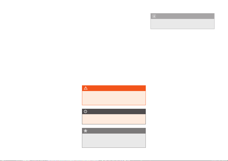
WARNING
Texts after this symbol contain informa-
tion about safety and w
arn you about
possible accident or injury risks.
CAUTION
Texts after this symbol indicate possible
damage to the vehicl
e.
For the sake of the environment
Texts after this symbol contain informa-
tion about the protection of the envir
on-
ment.
®
Note
Texts after this symbol contain addition-
al information.


Table of Contents
Table of Contents
Gener
al vie
ws of the v
ehicle . . . . . . . . 7
Exterior view . . . . . . . . . . . . . . . . . . . . . . . . . . . . . . . 7
Overview (left hand drive) . . . . . . . . . . . . . . . . 8
Interior view . . . . . . . . . . . . . . . . . . . . . . . . . . . . . . . 9
Safety . . . . . . . . . . . . . . . . . . . . . . . . . . . . . . . . . . . . 10
Safe driving . . . . . . . . . . . . . . . . . . . . . . . . . . . . . . . 10
Advice about driving . . . . . . . . . . . . . . . . . . . . . . . . 10
Correct sitting position of vehicle occu-
pants . . . . . . . . . . . . . . . . . . . . . . . . . . . . . . . . . . . . . . . 11
Pedal area . . . . . . . . . . . . . . . . . . . . . . . . . . . . . . . . . 13
Seat belts . . . . . . . . . . . . . . . . . . . . . . . . . . . . . . . . . 14
The whys and wherefores of seat belts . . . . . 14
How to properly adjust your seat belt . . . . . . 17
Seat belt tensioners . . . . . . . . . . . . . . . . . . . . . . . . 19
Airbag system . . . . . . . . . . . . . . . . . . . . . . . . . . . . . 20
Brief introduction . . . . . . . . . . . . . . . . . . . . . . . . . . . 20
Operation of the airbags . . . . . . . . . . . . . . . . . . . 22
Transporting children safely . . . . . . . . . . . . . . 26
Safety for children . . . . . . . . . . . . . . . . . . . . . . . . . . 26
Emergencies . . . . . . . . . . . . . . . . . . . . . . . . . . . . 34
Self-help . . . . . . . . . . . . . . . . . . . . . . . . . . . . . . . . . . 34
Emergency equipment . . . . . . . . . . . . . . . . . . . . . 34
Tyre repairs . . . . . . . . . . . . . . . . . . . . . . . . . . . . . . . . . 35
Changing a wheel . . . . . . . . . . . . . . . . . . . . . . . . . . 38
Changing the windscreen wiper blades . . . . 43
Jump start . . . . . . . . . . . . . . . . . . . . . . . . . . . . . . . . . . 44
Tow start and towing . . . . . . . . . . . . . . . . . . . . . . . 46
Fuses and bulbs . . . . . . . . . . . . . . . . . . . . . . . . . . . 47
Fuses . . . . . . . . . . . . . . . . . . . . . . . . . . . . . . . . . . . . . . . 47
Changing bulbs . . . . . . . . . . . . . . . . . . . . . . . . . . . . 49
Operation . . . . . . . . . . . . . . . . . . . . . . . . . . . . . . . 55
Controls and displays . . . . . . . . . . . . . . . . . . . . 55
Interior view . . . . . . . . . . . . . . . . . . . . . . . . . . . . . . . . 55
Instruments and warning/control
lamps . . . . . . . . . . . . . . . . . . . . . . . . . . . . . . . . . . . . . . 56
Instrument panel . . . . . . . . . . . . . . . . . . . . . . . . . . . 56
Using the instrument panel . . . . . . . . . . . . . . . . . 63
Control lamps . . . . . . . . . . . . . . . . . . . . . . . . . . . . . . 65
Opening and closing . . . . . . . . . . . . . . . . . . . . . . 67
Set of vehicle keys . . . . . . . . . . . . . . . . . . . . . . . . . . 67
Central locking . . . . . . . . . . . . . . . . . . . . . . . . . . . . . 69
Doors . . . . . . . . . . . . . . . . . . . . . . . . . . . . . . . . . . . . . . 72
Rear lid . . . . . . . . . . . . . . . . . . . . . . . . . . . . . . . . . . . . . 73
Window controls . . . . . . . . . . . . . . . . . . . . . . . . . . . 75
Lights . . . . . . . . . . . . . . . . . . . . . . . . . . . . . . . . . . . . . . 76
Vehicle lighting . . . . . . . . . . . . . . . . . . . . . . . . . . . . . 76
Interior lights . . . . . . . . . . . . . . . . . . . . . . . . . . . . . . . 81
Visibility . . . . . . . . . . . . . . . . . . . . . . . . . . . . . . . . . . . 82
Windscreen wiper and rear window wiper
systems . . . . . . . . . . . . . . . . . . . . . . . . . . . . . . . . . . . . 82
Mirrors . . . . . . . . . . . . . . . . . . . . . . . . . . . . . . . . . . . . . 84
Sun protection . . . . . . . . . . . . . . . . . . . . . . . . . . . . . 85
Seats and head restraints . . . . . . . . . . . . . . . . 86
Adjusting seats . . . . . . . . . . . . . . . . . . . . . . . . . . . . . 86
Headrest . . . . . . . . . . . . . . . . . . . . . . . . . . . . . . . . . . . 87
Seat functions . . . . . . . . . . . . . . . . . . . . . . . . . . . . . . 88
Transport and practical equipment . . . . . . 89
Storing objects . . . . . . . . . . . . . . . . . . . . . . . . . . . . . 89
Luggage compartment . . . . . . . . . . . . . . . . . . . . . 90
Roof carrier* . . . . . . . . . . . . . . . . . . . . . . . . . . . . . . . 92
Storage compartment . . . . . . . . . . . . . . . . . . . . . 94
Drink holder . . . . . . . . . . . . . . . . . . . . . . . . . . . . . . . . 96
Power sockets . . . . . . . . . . . . . . . . . . . . . . . . . . . . . . 97
Smartphone support . . . . . . . . . . . . . . . . . . . . . . . 98
Air conditioning . . . . . . . . . . . . . . . . . . . . . . . . . . . 100
Heating, ventilation and cooling . . . . . . . . . . . . 100
Stationary air conditioning . . . . . . . . . . . . . . . . . 104
Infotainment System . . . . . . . . . . . . . . . . . . 107
Introduction . . . . . . . . . . . . . . . . . . . . . . . . . . . . . . . 107
Safety warnings . . . . . . . . . . . . . . . . . . . . . . . . . . . . 107
Overview of the unit . . . . . . . . . . . . . . . . . . . . . . . . 109
General instructions for use . . . . . . . . . . . . . . . . 111
Operating modes . . . . . . . . . . . . . . . . . . . . . . . . . 115
Radio . . . . . . . . . . . . . . . . . . . . . . . . . . . . . . . . . . . . . . . 115
Digital radio mode* . . . . . . . . . . . . . . . . . . . . . . . . 118
Media . . . . . . . . . . . . . . . . . . . . . . . . . . . . . . . . . . . . . . 120
Telephone . . . . . . . . . . . . . . . . . . . . . . . . . . . . . . . . . . 125
Drive Mii App* . . . . . . . . . . . . . . . . . . . . . . . . . . . . . . 128
Connectivity . . . . . . . . . . . . . . . . . . . . . . . . . . . . . . 129
Cybersecurity . . . . . . . . . . . . . . . . . . . . . . . . . . . . . . 129
SEAT CONNECT . . . . . . . . . . . . . . . . . . . . . . . . . . . . 130
Driving . . . . . . . . . . . . . . . . . . . . . . . . . . . . . . . . . . . 133
Drive system and driving . . . . . . . . . . . . . . . . . 133
Driving indications . . . . . . . . . . . . . . . . . . . . . . . . . . 133
Connecting and disconnecting the drive
system . . . . . . . . . . . . . . . . . . . . . . . . . . . . . . . . . . . . . 135
Gear selection . . . . . . . . . . . . . . . . . . . . . . . . . . . . . 140
Hill driving assistant . . . . . . . . . . . . . . . . . . . . . . . . 143
Steering . . . . . . . . . . . . . . . . . . . . . . . . . . . . . . . . . . . . 143
Driving profiles . . . . . . . . . . . . . . . . . . . . . . . . . . . . . 144
Driving tips . . . . . . . . . . . . . . . . . . . . . . . . . . . . . . . . . 145
Driver assistance systems . . . . . . . . . . . . . . . . 146
Cruise control system (CCS)* . . . . . . . . . . . . . . 146
Lane Assist* . . . . . . . . . . . . . . . . . . . . . . . . . . . . . . . . 148
5

Table of Contents
Braking and parking . . . . . . . . . . . . . . . . . . . . . . . 150
Braking system . . . . . . . . . . . . . . . . . . . . . . . . . . . . . 150
Stabilisation and brake assistance sys-
t
ems . . . . . . . . . . . . . . . . . . . . . . . . . . . . . . . . . . . . . . . .
152
P
arking . . . . . . . . . . . . . . . . . . . . . . . . . . . . . . . . . . . . . 154
Help with parking and manoeuvring . . . . . 155
Parking distance warning system* . . . . . . . . . 155
Towing bracket device . . . . . . . . . . . . . . . . . . . . 157
Trailer mode . . . . . . . . . . . . . . . . . . . . . . . . . . . . . . . . 157
Practical tips . . . . . . . . . . . . . . . . . . . . . . . . . . . 158
High-voltage battery . . . . . . . . . . . . . . . . . . . . . 158
Safety warnings relating to the high-volt-
age network and the high-voltage bat-
tery . . . . . . . . . . . . . . . . . . . . . . . . . . . . . . . . . . . . . . . . . 158
Charging the high-voltage battery . . . . . . . . . 160
Charging cable . . . . . . . . . . . . . . . . . . . . . . . . . . . . 170
Verification and replacement . . . . . . . . . . . . 174
Engine compartment . . . . . . . . . . . . . . . . . . . . . . . 174
Cooling system . . . . . . . . . . . . . . . . . . . . . . . . . . . . 178
Brake fluid . . . . . . . . . . . . . . . . . . . . . . . . . . . . . . . . . . 180
Windscreen washer reservoir . . . . . . . . . . . . . . . 181
12-volt battery . . . . . . . . . . . . . . . . . . . . . . . . . . . . . . 182
Wheels . . . . . . . . . . . . . . . . . . . . . . . . . . . . . . . . . . . . 186
Wheels and tyres . . . . . . . . . . . . . . . . . . . . . . . . . . . 186
Tyre pressure monitor system* . . . . . . . . . . . . . 192
Maintenance . . . . . . . . . . . . . . . . . . . . . . . . . . . . 194
SEAT Maintenance Programme . . . . . . . . . . 194
Service intervals . . . . . . . . . . . . . . . . . . . . . . . . . . . . 194
Additional service offers . . . . . . . . . . . . . . . . . . . . 195
Warranty . . . . . . . . . . . . . . . . . . . . . . . . . . . . . . . . . . . 196
Vehicle maintenance . . . . . . . . . . . . . . . . . . . . . 196
Maintenance and cleaning . . . . . . . . . . . . . . . . . 196
Accessories and modifications to the ve-
hicle . . . . . . . . . . . . . . . . . . . . . . . . . . . . . . . . . . . . . . . 202
Accessories, spare parts and repair work . . . 202
Information for the user . . . . . . . . . . . . . . 204
Information for the user . . . . . . . . . . . . . . . . . . . 204
Information stored by the control units . . . . . . 204
Other important information . . . . . . . . . . . . . . . . 205
Information about the EU Directive
2014/53/EU . . . . . . . . . . . . . . . . . . . . . . . . . . . . . . . . 207
Technical data . . . . . . . . . . . . . . . . . . . . . . . . . 211
Indications about the technical data . . . . 211
Important information . . . . . . . . . . . . . . . . . . . . . . 211
Index . . . . . . . . . . . . . . . . . . . . . . . . . . . . . . . . . . . . . . 215
6
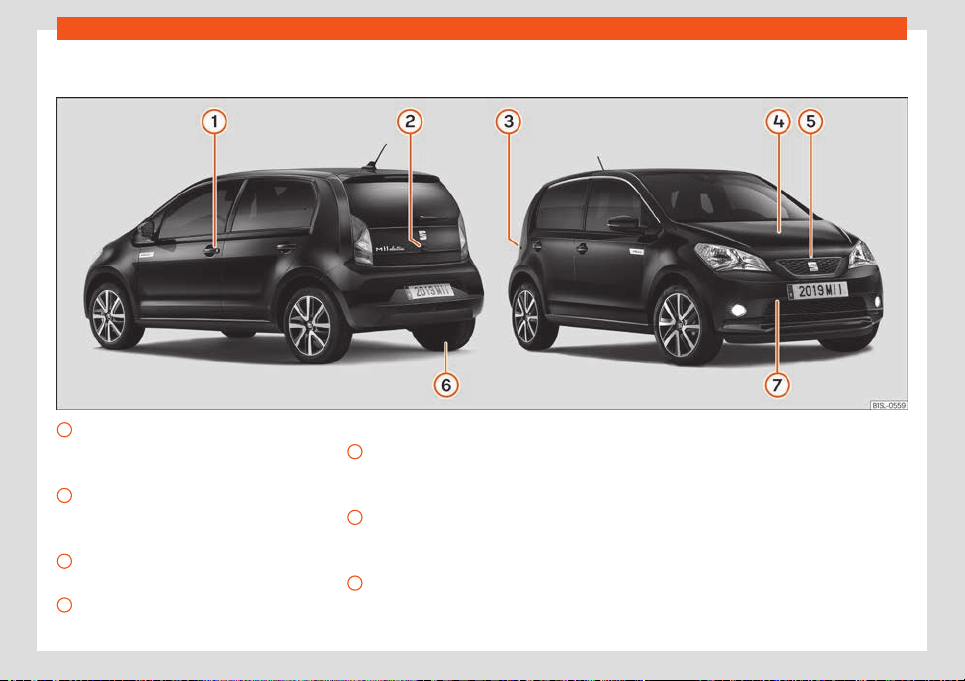
General views of the vehicle
Exterior view
Opening and closing
– Doors
›
›
›
page 72
– Central locking
›››
page 69
Rear lid
– Opening from outside
›››
page 74
– Emergency opening
›››
page 75
High-voltage battery charging socket
– Open/Close cap
›››
page 160
Levels control
– Brake fluid
›››
page 180
1
2
3
4
– Battery 12V
›
›
›
page 182
Bonnet
– Unlocking lever
›››
page 177
– Open/close
›››
page 177
Action in the event of a puncture
– Anti-puncture kit
›››
page 35
– Wheel change
›››
page 38
Towing the vehicle
– Towline anchorage
›››
page 46
5
6
7
7
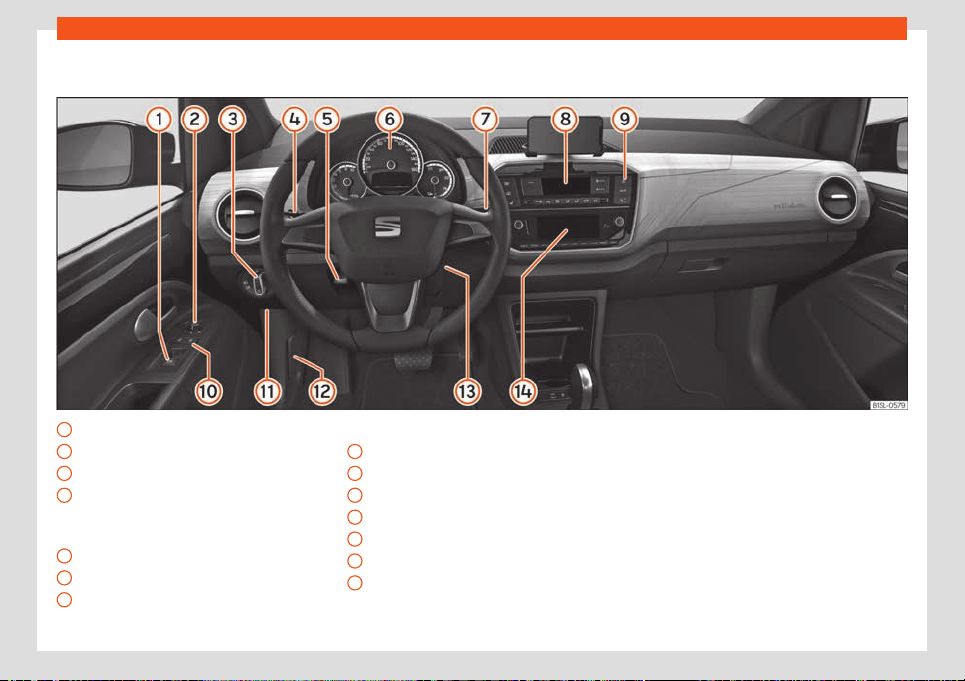
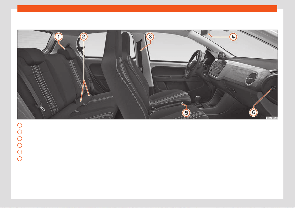
General views of the vehicle
Overview (left hand drive)
Electric windows
›
›
›
page 75
Exterior mirror adjustment
›››
page 84
Headlight switch
›››
page 77
Turn signal and main beam lever
›››
page 78
Cruise control
›››
page 146
Steering wheel adjustment
›››
page 13
Warning lamps
›››
page 65
Wipers and rear window wiper
›››
page 82
1
2
3
4
5
6
7
Driver information system
›
›
›
page 63
Air conditioning
›››
page 100
Hazard warning lights
›››
page 80
Central locking
›››
page 69
Fuses
›››
page 47
Open bonnet lever
›››
page 177
Ignition lock
›››
page 135
Infotainment system (factory fitted)
›››
page 107
8
9
10
11
12
13
14
8
Safety
Safety
Saf
e driving
Advice about driving
Saf
et
y first!
WARNING
●
This manual contains import
ant informa-
tion about the operation of the vehicle,
both for the driver and the passengers. The
other sections of the on-board documenta-
tion also contain further information that
you should be aware of for your own safety
and for the safety of your passengers.
●
Ensure that the on-board documentation
is kept in the vehicle at all times. This is es-
pecially important when lending or selling
the vehicle to another person.
Before driving
For your own safety and the safety of your
passengers, al
w
ays not
e the following points
before every trip:
–
Make sure that the vehicle's lights and turn
signals are working properly.
–
Check tyre pressure.
–
Ensure that all windows provide a clear and
good view of the surroundings.
–
Do not block the entrance of air to the elec-
tric drive train or cover it with blankets or in-
sulating materials.
–
Make sure all luggage is secured
›››
page 89.
–
Make sure that no objects can interfere with
the pedals.
–
Adjust front seat, head restraint and mirrors
properly according to your size.
–
Ensure that the passengers in the rear seats
always have the head restraints in the in-
use position
›››
page 87.
–
Instruct passengers to adjust the head re-
straints according to their height.
–
Protect children with appropriate child
seats and properly applied seat belts
›››
page 26.
–
Assume the correct sitting position. Instruct
your passengers also to assume a proper
sitting position
›››
page 11.
–
Fasten your seat belt securely. Instruct your
companions to fasten their seat belt prop-
erly
›››
page 14.
Factors influencing safety
You, as the driver, are responsible for your
safety and that of your companions.
–
Al
ways pay attention to traffic and do not
get distracted by passengers or telephone
calls.
–
Never drive when your driving ability is im-
paired (e.g. by medication, alcohol, drugs).
–
Observe traffic laws and speed limits.
–
Always reduce your speed as appropriate
for road, tr
affic and weather conditions.
–
On long trips, stop regularly to rest, at least
every two hours.
–
If possible, avoid driving when you are tired
or stressed.
WARNING
Driving under the influence of alcohol,
drugs, medication or narcotics may result
in se
vere accidents and even loss of life.
●
Alcohol, drugs, medication and narcotics
may significantly alter perception, affect
reaction times and safety while driving,
which could result in the loss of control of
the vehicle.
10
Safe driving
Safety equipment
Never put your safety or the safety of your
passengers in danger. In the ev
ent of an acci-
dent, the safety equipment may reduce the
risk of injury. The following points cover part
of the safety equipment in your SEAT
1)
:
●
three-point seat belts,
●
belt tension limiter for the front and rear
seats
●
belt tensioners for the front and rear seats,
●
front and rear airbags,
●
side airbags on the backs of the front seats,
and head airbags for the front and r
ear seats.
●
“ISOFIX” anchor points for child seats in the
rear side seats with the “ISOFIX” system,
●
rear head restraints with in-use position and
non-use position,
●
adjustable steering column.
The safety equipment mentioned above
works together to provide you and your pas-
sengers with the best possible protection in
the event of an accident. However, these
safety systems can only be effective if you
and your passengers are sitting in a correct
position and use this equipment properly.
Safety is everyone's business!
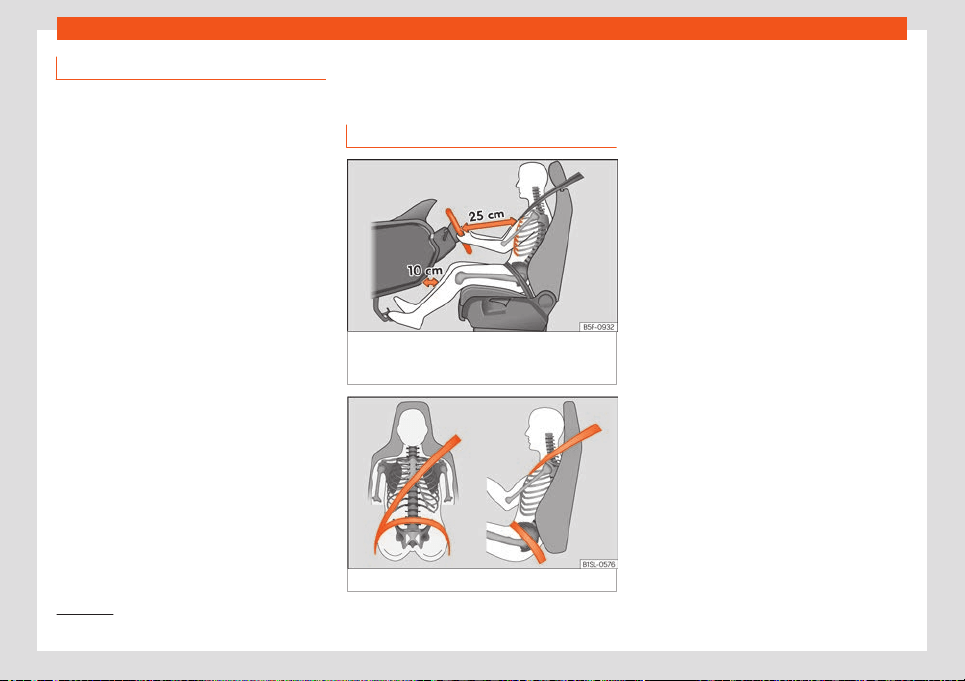
Correct sitting position of
vehicle occupants
Correct position on the seat
Fig. 2 The correct distance between the driver
and the st
eering wheel must be at l
east 25 cm
(10 inches).
Fig. 3 Seat belt adjusted correctly.
The correct sitting positions for the driver and
passengers ar
e sho
wn bel
ow.
If your physical constitution prevents you
from maintaining the correct sitting position,
contact a specialised workshop for help with
any special devices. The seat belt and airbag
can only provide optimum protection if a cor-
rect sitting position is adopted. SEAT recom-
mends taking your car in for technical serv-
ice.
For your own safety and to reduce the risk of
injury in the event of an accident or sudden
braking or manoeuvre, SEAT recommend the
following positions:
Valid for all vehicle occupants:
●
Keep the back of your neck as close as
possible to the headrest
›››
Fig. 3.
●
Always keep your feet in the footwell while
the vehicle is in motion.
●
Adjust and fasten your seat belt correctly
›››
page 17.
The following also applies to the driver:
●
Move the seat backrest to an almost up-
right position so that your back rests com-
pletely against it.
●
Move the steering wheel so it is at least
25 cm (10 inches) away from the sternum
»
1)
Depending on the version/market.
11
Safety
›››
Fig. 2 and you can hol
d it with both hands
on both sides, on the out
er part, with your
arms slightly bent.
●
The st
eering wheel must always point to-
wards the chest and never towards the face.
●
Move the seat in such a way that you can
step on the pedals with your knees slightly
bent and with a distance between the knees
and the dashboard of at least 10 cm (4 in-
ches)
›››
Fig. 2.
●
Adjust the height of the seat so that you
can reach the top of the steering wheel.
●
Always keep both feet in the footwell so
that you have the vehicle under control at all
times.
For the passenger, the following applies:
●
Move the seat backrest to an almost up-
right position so that your back rests com-
pletely against it.
●
Move the seat as far back as possible (mini-
mum 25 cm between the chest and the in-
strument panel check translation). If you are
sitting closer than 25 cm, the airbag system
cannot protect you properly.
Number of seats
The vehicle has 4 seats, 2 in the fr
ont and 2 in
the r
ear
. All seats are equipped with a safety
belt.
WARNING
Sitting in an incorrect position may in-
crease the risk of sev
ere or lethal injuries in
the event of sudden braking or manoeu-
vring, in case of collision or accident and if
the airbags deploy.
●
Before starting the car, all passengers
must be sitting in a correct position and
stay like that for the entire journey. This al-
so applies to a correct use of the seat belt.
●
The maximum amount of people in the
vehicle is the same as the amount of seats
with seat belts.
●
For children, always use a certified pro-
tection system, certified and suited for their
weight and height
›››
page 26.
●
While driving, always keep your feet in
the footwell. Never place them over the
seat or the instrument panel, for example,
or outside the window. Otherwise the air-
bag and seat belt may offer insufficient
protection and also increase the risk of in-
jury in the event of an accident.
Risks of sitting in an incorrect posi-
tion
If seat belts are worn incorrectly or not at all,
the risk of se
v
er
e or lethal injuries increases.
Seat belts can provide optimal protection on-
ly if the belt web is properly worn. Incorrect
sitting positions substantially reduce the pro-
tective function of seat belts and, therefore,
increase the risk of severe or even lethal inju-
ries. The risk of severe or fatal injuries is espe-
cially heightened when a deploying airbag
strikes a vehicle occupant who has assumed
an incorrect sitting position. The driver is re-
sponsible for all people, particularly children,
inside the vehicle.
The following list contains examples of incor-
rect sitting positions that could be dangerous
for all vehicle occupants.
When the vehicle is in motion:
●
Never stand in the vehicle.
●
Never stand on the seats.
●
Never kneel on the seats.
●
Never tilt your seat backrest too far to the
rear.
●
Never lean against the instrument panel.
●
Never lie on the rear seats.
●
Never sit on the front edge of a seat.
●
Never sit sideways.
●
Never lean out of a window.
●
Never put your feet out of a window.
●
Never put your feet on the instrument panel.
●
Never place your feet on the bench or on
the backrest of the seat.
●
Never travel in a footwell.
●
Never sit on the armrests.
12
Safe driving
●
Ne
v
er tr
avel without wearing the seat belt.
●
Never travel in the luggage compartment.
WARNING
Sitting in an incorrect position increases
the risk of sever
e or fatal injuries in the
event of accidents and sudden braking or
manoeuvres.
●
All occupants must sit correctly during
the journey and wear the seat belt correct-
ly.
●
Occupants of the vehicle that are not sit-
ting correctly, not wearing the seat belt or
are not at a proper distance of the airbag
risk suffering very serious or lethal injuries,
especially if the airbags deploy and strike
them.
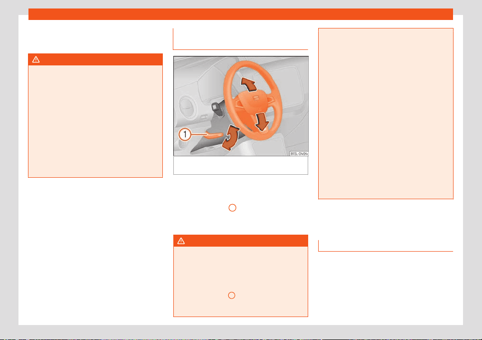
Steering wheel position adjust-
ment
Fig. 4
Lever in the lower left side of the steering
column.
Adjust the steering wheel before your trip and
only when the v
ehicl
e is st
ationary.
●
Pull the
›››
Fig. 4
1
lever down, move the
st
eering wheel t
o the desir
ed position and lift
the lever back up until it locks.
WARNING
Incorrect use of the steering wheel adjust-
ment function and an incorrect adjustment
of the steering wheel can r
esult in severe or
fatal injury.
●
After adjusting the steering column, push
the lever
›››
Fig. 4
1
firmly upwards to en-
sure the steering wheel does not acciden-
t
ally change position while driving.
●
Never adjust the st
eering wheel while the
vehicle is in motion. If you need to adjust
the steering wheel while the vehicle is in
motion, stop safely and make the proper
adjustment.
●
The adjusted steering wheel should be
facing your chest and not your face so as
not to hinder the driver's front airbag pro-
tection in the event of an accident.
●
When driving, always hold the steering
wheel with both hands on the outside of the
ring at the 9 o'clock and 3 o'clock positions
to reduce injuries when the driver's front
airbag deploys.
●
Never hold the steering wheel at the 12
o'clock position or in any other manner
(e.g. in the centre of the steering wheel). In
such cases, if the driver's airbag deploys,
you may sustain injuries to your arms,
hands and head.
Pedal area
P
edal
s
–
Make sure you can always step on the
br
ak
e and accel
erator pedals without any
problems.
–
Ensure that the pedals can return unim-
paired to their initial positions.
»
13
Safety
–
Ensur
e that the fl
oor mats ar
e securely fas-
tened during the trip and do not obstruct
the pedals
›››
.
Only use fl
oor mats which l
eav
e the pedals
clear and which are secured to prevent them
from slipping. You can obtain suitable floor
mats from a specialised dealership. Fasten-
ers* for floor mats are fitted in the footwells.
If a brake circuit fails, the brake pedal must be
pressed down thoroughly in order to stop the
vehicle.
Wear suitable footwear
Always wear shoes which support your feet
properly and give you a good feeling for the
pedals.
WARNING
●
Restricting pedal operation can l
ead to
critical situations while driving.
●
Never lay or fit floor mats or other floor
coverings over the original floor mats. This
would reduce the pedal area and could ob-
struct the pedals. Risk of accident.
●
Never place objects in the driver footwell.
An object could move into the pedal area
and impair pedal operation.
Seat belts
The whys and wher
ef
or
es of
seat belts
Control lamps
It lights up red
Driver or passenger has not fastened seat belt.
Objects on the front passenger seat.
Remov
e the objects from the front passenger seat
and store them safely.
The control lamp lights up t
o r
emind the
driv
er to fasten their seat belt.
Before starting the vehicle:
●
Fasten your seat belt securely.
●
Instruct your passengers to fasten their
seat belts properly before driving off.
●
Protect children by using a child seat ac-
cording to the child's height and weight
›››
page 26.
When starting to drive, if the vehicle's speed
exceeds approx. 25 km/h (15 mph) and the
seat belts are not fastened or are unfastened
while driving, a warning sound will be heard
for a few seconds. The warning light will also
flash .
The lamp goes out when the driver and
passenger seat belts are fastened with the
ignition switched on.
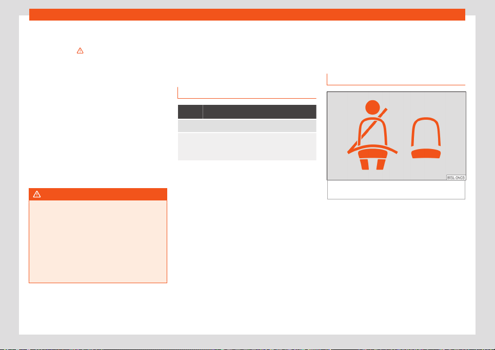
Rear seat belts fastened display*
Fig. 5
Indication of seat belt status in the rear
seats on the instrument panel displ
ay
When the ignition is switched on, the status
displ
ay of the seat belts
›
›
›
Fig. 5 informs the
driver on the instrument panel display wheth-
er the occupants of the rear seats have their
seat belts fastened.
It indicates that the corresponding seat
is empty.
Indicates that the seat is occupied and
the occupant is wearing the seat belt.
The seat belt status flashes for a maximum of
30 seconds when a seat belt in the rear seats
is unfastened while the vehicle is in motion. An
14

Seat belts
audible warning will also be heard if the vehi-
cl
e is tr
av
elling at over 25 km/h (15 mph).
If a seat belt is fastened or unfastened while
driving in some of the rear seats, the seat belt
status is displayed for approximately 30 sec-
onds. The indication can be hidden by press-
ing the
button on the instrument panel.
The protective function of seat
belts
Fig. 6
Drivers with properly worn seat belts
will not be thr
o
wn f
orward in the event of sud-
den braking.
Properly worn seat belts hold the occupants
in the pr
oper position. They al
so help pr
event
uncontrolled movements that may result in
serious injury and reduce the risk of being
thrown out of the vehicle in case of an acci-
dent.
Vehicle occupants wearing their seat belts
correctly benefit greatly from the ability of
the belts to absorb kinetic energy. In addition,
the front part of your vehicle and other pas-
sive safety features (such as the airbag sys-
tem) are designed to absorb the kinetic ener-
gy released in a collision. Taken together, all
these features reduce the releasing kinetic
energy and consequently, the risk of injury.
This is why it is so important to fasten seat
belts before every trip, even when "just driving
around the corner".
Ensure that your passengers wear their seat
belts as well. Accident statistics have shown
that wearing seat belts is an effective means
of substantially reducing the risk of injury and
improving the chances of survival when in-
volved in a serious accident. Furthermore,
properly worn seat belts improve the protec-
tion provided by airbags in the event of an
accident. For this reason, wearing a seat belt
is required by law in most countries.
Although your vehicle is equipped with air-
bags, the seat belts must be fastened and
worn. The front airbags, for example, are only
triggered in some cases of head-on collision.
The front airbags will not be triggered during
minor frontal or side collisions, rear-end colli-
sions, overturns or accidents in which the air-
bag trigger threshold value in the control unit
is not exceeded.
Important safety instructions for
the use of seat belts
–
Always wear the seat belt as described in
this section.
–
Ensure that the seat belts can be fastened
at all times and are not damaged.
WARNING
●
If seat belts are worn incorr
ectly or not at
all, the risk of severe injuries increases. The
optimal protection from seat belts can be
achieved only if you use them properly.
●
Never allow two passengers (even chil-
dren) to share the same seat belt.
●
Never unbuckle a seat belt while the ve-
hicle is in motion. Risk of fatal injury.
●
The seat belt should never lie on hard or
fragile objects (such as glasses or pens,
etc.) because this can cause injuries.
●
Do not allow the seat belt to be damaged
or jammed, or to rub on any sharp edges.
●
Never wear the seat belt under the arm or
in any other incorrect position.
●
Bulky and unfastened clothing (such as
an overcoat over a sweater) impairs the
proper fit and function of the seat belts, re-
ducing their capacity to protect.
●
The slot in the seat belt buckle must not
be blocked with paper or other objects, as
this can prevent the latch plate from en-
gaging securely.
»
15
Safety
●
Never use seat belt clips, f
astening rings
or similar items to alter the position of the
belt webbing.
●
Frayed or torn seat belts or damage to
the connections, belt retractors or parts of
the buckle could cause severe injuries in
the event of an accident. Therefore, you
must check the condition of all seat belts
at regular intervals.
●
Seat belts which have been worn in an
accident and have been stretched must be
replaced by a specialised workshop. Re-
newal may be necessary even if there is no
apparent damage. The belt anchorage
should also be checked.
●
Do not attempt to repair a damaged seat
belt yourself. The seat belts must not be re-
moved or modified in any way.
●
The belts must be kept clean, otherwise
the retractors may not work properly.
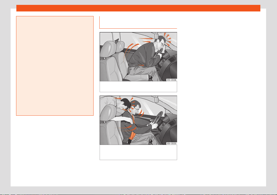
Head-on collisions and the laws of
physics
Fig. 7
A driver not wearing a seat belt is thrown
f
orw
ar
d violently.
Fig. 8
The unbelted passenger in the rear seat
is thr
o
wn f
orward violently, hitting the driver
who is wearing a seat belt.
The effects of the laws of physics in the case
of a head-on collision ar
e easy t
o e
xplain: the
moment a vehicle starts moving, a type of en-
ergy called “kinetic energy” starts acting on
both the vehicle and its passengers.
The amount of “kinetic energy” depends on
the speed of the vehicle and on the weight of
the vehicle and of its passengers. The higher
they are, the more energy there is to be “ab-
sorbed” in the event of an accident.
The most significant factor, however, is the
speed of the vehicle. If the speed doubles
from 25 km/h (15 mph) to 50 km/h (30 mph),
for example, the corresponding kinetic ener-
gy is multiplied by four.
Given that the passengers of the vehicle in
our example do not have their seat belts fas-
tened, in the event of a collision the entire
amount of the passengers' kinetic energy will
be only absorbed by the mentioned impact.
Even at speeds of 30 km/h (19 mph) to
50 km/h (30 mph), the forces acting on bod-
ies in a collision can easily exceed one tonne
(1000 kg). At greater speed these forces are
even higher.
Vehicle occupants not wearing seat belts are
not “attached” to the vehicle. In a head-on
collision, they will move forward at the same
speed their vehicle was travelling just before
the impact. This example applies not only to
head-on collisions, but to all accidents and
collisions.
Even at low speeds the forces acting on the
body in a collision are so great that it is not
16
Seat belts
possible to brace oneself with one's hands. In
a fr
ont
al collision, unbelt
ed passengers are
thrown forward and will make violent contact
with the steering wheel, dash panel, wind-
screen or whatever else is in the way
›››
Fig. 7.
It is also important for rear passengers to
wear seat belts properly, as they could other-
wise be thrown forward violently through the
vehicle interior in an accident. Passengers in
the rear seats who do not use seat belts en-
danger not only themselves but also the front
occupants
›››
Fig. 8.
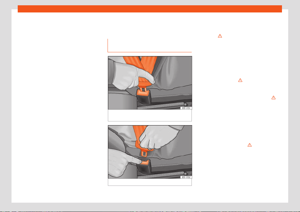
How to properly adjust your
seat belt
Fastening and unfastening the seat
belt
Fig. 9 Insert the latch plate of the seat belt into
the buckl
e
.
Fig. 10 Release the seat belt's buckle.
Properly worn seat belts hold the vehicle oc-
cupants in the position that most pr
ot
ects
them in the e
vent of an accident or sudden
braking
›››
.
F
ast
ening the seat belt
F
asten your seat belt before each trip.
●
Adjust the front seat and head restraint cor-
rectly
›››
page 11.
●
Engage the seat backrest of the rear seat in
an upright position
›››
.
●
Pull the latch plate and place the belt web-
bing e
v
enly acr
oss your chest and lap. Do
not twist the seat belt when doing so
›››
.
●
Engage the latch plate in the buckle of the
corr
esponding seat
›
›
›
Fig. 9.
●
Pull the belt to ensure that the latch plate is
securely engaged in the buckle.
Releasing the seat belt
Only unfasten the seat belt when the vehicle
has come to a standstill
›››
.
●
Press the red button on the buckle
›
›
›
Fig. 10. The latch plate is released from the
buckle.
●
Guide the belt back by hand so that it rolls
up easily and the trim will not be damaged.
»
17
Safety
WARNING
●
The seat belt cannot offer its full prot
ec-
tion unless the seat backrest is in an up-
right position and the seat belt is worn cor-
rectly, according to your size.
●
Unbuckling your seat belt while the vehi-
cle is in motion can cause severe or fatal
injuries in the event of an accident or sud-
den braking.
●
The seat belt itself, or a loose seat belt,
can cause severe injuries if the belt moves
from hard areas of the body to soft areas
(e.g. the stomach).
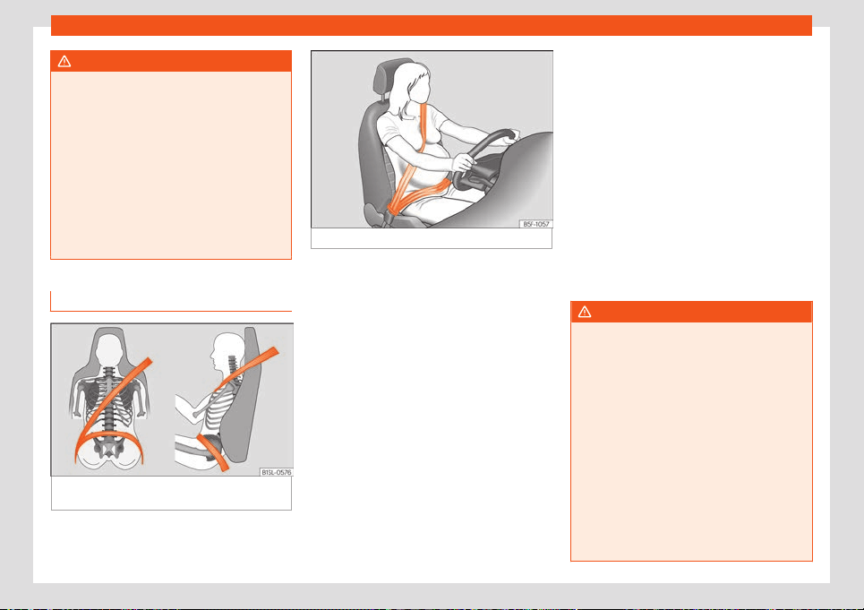
Correct seat belt position
Fig. 11
Seat belt adjusted correctly, front and
side vie
w
.
Fig. 12 Position of seat belt during pregnancy.
Seat belts offer their maximum protection in
the e
v
ent of an accident and r
educe the risk
of sustaining severe or fatal injuries only when
they are properly positioned. Furthermore, if
the webbing is correctly positioned, the seat
belt will hold the vehicle occupants in the op-
timum position to ensure the airbag provides
the maximum protection. The seat belt must
therefore always be worn and the webbing
correctly positioned.
Incorrectly worn seat belts can cause severe
or even fatal injuries
›››
page 11, Correct sit-
ting position of vehicle occupants.
●
The shoulder part of the seat belt must lie
on the centre of the shoulder, never across
the neck or the arm, under the arm or behind
the shoulder.
●
The lap part of the seat belt must lie across
the pelvis, never across the stomach.
●
The seat belt must lie flat and fit comforta-
bly. Pull the belt tight if necessary to take up
any slack.
In the case of pregnant women, the seat belt
must lie evenly across the chest and as low
as possible over the pelvis, never across the
stomach and must be worn properly at all
times during the pregnancy
›››
Fig. 12.
Adapting the position of the belt webbing
to your size
The seat belt can be adapted using the fol-
lowing equipment:
●
Belt height adjustment for the front seats.
WARNING
An incorrectly worn seat belt web can
cause sever
e or fatal injuries in the event of
an accident.
●
The shoulder part of the seat belt must lie
on the centre of the shoulder, never across
the neck or the arm.
●
The seat belt must lie flat and fit comfort-
ably on the torso
●
The lap part of the seat belt must lie
across the pelvis, never across the stom-
ach. The seat belt must lie flat and fit com-
fortably on the pelvis Pull the belt tight if
necessary to take up any slack.
●
For pregnant women, the lap part of the
seat belt must lie as low as possible over
18
Seat belts
the pelvis and always lie flat, “surrounding”
the stomach
››
›
Fig. 12.
●
Do not twist the seat belt while it is fas-
tened.
●
Once the seat belt is positioned correct-
ly, don't pull it away from your body with
your hand.
●
Do not lie the seat belt across rigid or
fragile objects, e.g. glasses, pens or keys.
●
Never use seat belt clips, retaining rings
or similar instruments to alter the position
of the belt webbing.
Note
If your physical constitution prevents you
from maintaining the corr
ect position of the
belt webbing, contact a specialised work-
shop for help with any special devices to
ensure the optimum protection of the seat
belt and airbag. SEAT recommends taking
your car in for technical service.
Seat belt tensioners
Ho
w the seat belt t
ensioner w
orks
The seat belts for the front and rear occu-
pants ar
e fitt
ed with belt t
ensioners.
The belt tensioners are activated by sensors,
although only in severe head-on, lateral and
rear-end collisions. This retracts and tightens
the seat belts, reducing the forward motion of
the occupants.
The belt pre-tensioners work in combination
with the airbag system. In case of overturn,
the pre-tensioners do not activate unless the
head airbags are deployed.
Belt tension limiter
The belt tension limiter reduces the force of
the seat belt on the body in the event of an
accident.
Note
●
If the seat belt tensioners are trigger
ed, a
fine dust is produced. This is normal and it
is not an indication of fire in the vehicle.
●
The relevant safety requirements must be
observed when the vehicle or components
of the system are scrapped. Specialised
workshops are familiar with these regula-
tions, which are also available to you.
Maintenance and disposal of seat
belt t
ensioners
The belt tensioners are components of the
seat belts that ar
e inst
all
ed in the seats of
your vehicle. If you work on the belt tension-
ers or remove and install parts of the system
when performing other repair work, the seat
belt may be damaged. The consequence
may be that, in the event of an accident, the
belt tensioners function incorrectly or may
not function at all.
So that the effectiveness of the seat belt ten-
sioner is not reduced and that removed parts
do not cause any injuries or environmental
pollution, regulations, which are known to the
specialised workshops, must be observed.
WARNING
●
Improper use or repairs not carried out by
qualified mechanics incr
ease the risk of se-
vere or fatal injuries. The belt tensioners
may fail to trigger or may trigger in the
wrong circumstances.
●
The seat belt tensioner, seat belt and au-
tomatic retractor cannot be repaired.
●
Any work on the belt tensioners and seat
belts, including the removal and refitting of
system parts in conjunction with other re-
pair work, must be performed by a special-
ised workshop only.
●
The belt tensioners will only provide pro-
tection for one accident and must be
changed if they have been activated.
For the sake of the environment
Airbag modules and belt tensioners may
contain perchl
orate. Observe the legal re-
quirements for their disposal.
19

Safety
Airbag system
Brief intr
oduction
Why is it so impor
t
ant to wear a
seat belt and to sit correctly?
For the inflating airbags to achieve the best
protection, the seat belt must al
ways be worn
properly and the correct sitting position must
be assumed.
The airbag system is not a substitute for seat
belts, but it is an integral part of the vehicle's
overall passive safety system. Please bear in
mind that the airbag system can only work
effectively when the vehicle occupants are
wearing their seat belts correctly and have
adjusted the head restraints properly. There-
fore, it is most important to properly wear the
seat belts at all times, not only because this is
required by law in most countries, but also for
your safety
›››
page 14, The whys and
wherefores of seat belts.
The airbag inflates in a matter of seconds, so
if you are not properly seated when the air-
bag is triggered, you may sustain fatal inju-
ries. Therefore, it is essential that all vehicle
occupants assume a correct sitting position
while travelling.
Sharp braking before an accident may cause
a passenger not wearing a seat belt to be
thrown forward into the area of the deploying
airbag. In this case, the inflating airbag may
inflict critical or f
atal injuries on the occupant.
This also applies to children.
Always maintain the greatest possible dis-
tance between yourself and the front airbag.
This way, the front airbags can completely
deploy when triggered, providing their maxi-
mum protection.
The most important factors for triggering the
airbag are the type of accident, the angle of
impact and the vehicle speed.
Whether or not the airbags are triggered de-
pends primarily on the vehicle deceleration
rate resulting from the collision and detected
by the control unit. If the vehicle deceleration
occurring during the collision and measured
by the control unit remains below the speci-
fied reference values, the front, side and/or
curtain airbags will not be triggered. Take into
account that the visible damage in a vehicle
involved in an accident, no matter how seri-
ous, is not a determining factor for the air-
bags to have been triggered.
WARNING
●
Wearing the seat belt incorrectly or as-
suming an incorr
ect sitting position can
lead to critical or fatal injuries.
●
All vehicle occupants, including children,
who are not properly belted can sustain
critical or fatal injuries if the airbag is trig-
gered. Children up to 12 years old should
always tr
avel on the rear seat. Never trans-
port children in the vehicle if they are not
restrained or the restraint system is not ap-
propriate for their age, size or weight.
●
To reduce the risk of injury from an inflat-
ing airbag, always wear the seat belt prop-
erly
›››
page 14.
Description of the airbag system
The airbag system offers additional protec-
tion f
or the occupants in combination with the
seat belts.
The airbag syst
em comprises the f
ollow-
ing modules (as per vehicle equipment):
●
Electronic control unit
●
Front airbags for driver and passenger
●
Side airbags for driver and passenger.
●
Head airbag
●
Airbag control lamp on the instrument
panel
›››
page 22
●
Key-operated switch for front passenger
airbag
●
Control lamp for disabled/enabled status
of the front passenger airbag.
20
Airbag system
The airbag system operation is monitored
el
ectr
onically. The airbag contr
ol lamp will il-
luminate for a few seconds every time the
ignition is switched on (self-diagnosis).
There is a fault in the system if the control
lamp :
●
does not light up when the ignition is
switched on
›››
page 22,
●
turns off after 4 seconds after the ignition is
switched on,
●
turns off and then lights up again after the
ignition is switched on,
●
illuminates or flashes while the vehicle is
moving.
The airbag system is not triggered if:
●
the ignition is switched off
●
there is a minor frontal collision
●
there is a minor side collision
●
there is a rear-end collision
●
the vehicle turns over.
WARNING
●
The seat belts and airbags can only pro-
vide maximum prot
ection if the occupants
are seated correctly
›››
page 11.
●
If a fault has occurred in the airbag sys-
tem, have the system checked immediately
by a specialised workshop. Otherwise
there is a danger that during a collision, the
system may fail to trigger, or not trigger
correctly.
Airbag activation
The airbags deploy extremely rapidly, within
thousands of a second, to pro
vide additional
protection in the event of an accident. A fine
dust may develop when the airbag deploys.
This is normal and it is not an indication of fire
in the vehicle.
The airbag system is only ready to function
when the ignition is on.
In special accidents instances, several air-
bags may activate at the same time.
In the event of minor head-on and side colli-
sions, rear-end collisions, overturning or roll-
over of the vehicle, airbags do not activate.
Activation factors
The conditions that lead to the airbag system
activating in each situation cannot be gener-
alised. Some factors play an important role,
such as the properties of the object the vehi-
cle hits (hard/soft), angle of impact, vehicle
speed, etc.
Deceleration trajectory is key for airbag acti-
vation.
The control unit analyses the collision trajec-
tory and activat
es the respective restraint
system.
If the deceleration rate is below the prede-
fined reference value in the control unit the
airbags will not be triggered, even though the
accident may cause extensive damage to the
car.
The following airbags are triggered in seri-
ous head-on collisions:
●
Driver airbag.
●
Front passenger front airbag
The following airbags are triggered in seri-
ous side-on collisions:
●
Front side airbag on the side of the acci-
dent.
●
Curtain (head) airbag on the side of the ac-
cident.
In an accident with airbag activation:
●
the interior lights switch on (if the interior
light switch is in the courtesy light position);
●
the hazard warning lights switch on;
●
all doors are unlocked;
●
the electric current supply to the motor is
cut off.
21
Safety
Operation of the airbags
Airbag syst
em contr
ol l
amps
It lights up on the combi-instru-
ment
Fault in the airbag system and seat belt tensioners .
Have the system checked immediately by a special-
ised workshop.
It lights up on the instrument
panel
Fault in the airbag system.
Have the system check
ed immediately by a special-
ised workshop.
Front passenger front airbag deactivated.
Check if the airbag should be kept deactiv
ated
Several warning and control lamps light up
f
or a f
e
w seconds when the ignition is switch-
ed on, signalling that the function is being
verified. They will switch off after a few sec-
onds.
If the airbag and seat belt tensioner system
control lamp remains on or flashes, it indi-
cates a malfunction in the airbag and seat
belt tensioner system
›››
. Have the system
check
ed immediat
ely by a specialised w
ork-
shop.
If the front passenger airbag is deactivated,
the lamp does not re-
main lit, or if it is lit together with the control
lamp on the instrument panel, there may
be a fault in the airbag system
›››
.
WARNING
In the event of a fault in the airbag and seat
belt tensioner system, the airbags and seat
belts may not trigger corr
ectly, may fail to
trigger or may even trigger unexpectedly.
●
The vehicle occupants run the risk of sus-
taining severe or fatal injuries. Have the
system checked immediately by a special-
ised workshop.
●
Do not mount a child seat in the front
passenger seat or remove the mounted
child seat! The front passenger front airbag
may deploy during an accident in spite of
the fault.
CAUTION
Always pay attention to any lit control
lamps and to the corr
esponding descrip-
tions and instructions to avoid damage to
the vehicle or harm to the occupants.
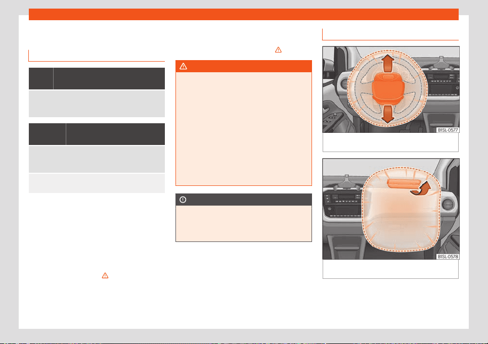
Front airbags
Fig. 13
Driver airbag located in steering
wheel
.
Fig. 14
Front passenger airbag located in in-
strument panel
.
The driver's front airbag is housed in the
st
eering wheel and that of the fr
ont passen-
ger
, on the instrument panel . Airbags are
identified by the word “AIRBAG”.
22
Airbag system
The airbag covers fold open and remain at-
t
ached t
o the st
eering wheel
›››
Fig. 13 and
the dash panel
›››
Fig. 14when the driver and
front passenger airbags, respectively, are
triggered.
In conjunction with the seat belts, the front
airbag system gives the front occupants ad-
ditional protection for the head and chest in
the event of a severe frontal collision
›››
.
Their special design all
o
ws the contr
olled es-
cape of the propellant gas when an occu-
pant puts pressure on the bag. Thus, the
head and chest are protected by the airbag.
After the collision, the airbag deflates suffi-
ciently to allow visibility.
WARNING
●
The deployment space between the fr
ont
passengers and the airbags must not in
any case be occupied by other passenger,
pets and objects.
●
The airbags provide protection for just
one accident; replace them once they have
deployed.
●
It is also important not to attach any ob-
jects such as cup holders or telephone
mountings to the surfaces covering the air-
bag units.
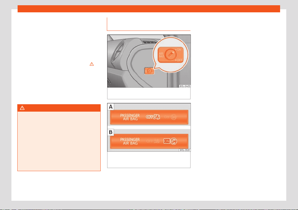
Activate and deactivate front pas-
senger fr
ont airbag
Fig. 15
Switch for activating and deactivating
the fr
ont passenger airbag.
Fig. 16
In the interior rear-view mirror bracket:
contr
ol l
amp f
or the deactivation of the front
passenger front airbag.
Deactivate the front passenger front airbag
only if you hav
e t
o use a r
ear-facing child
seat in the front passenger seat.
SEAT recommends fitting the child seat in the
rear seat to avoid having to deactivate the
front passenger airbag.
When the front passenger airbag is deacti-
vated, this means that only the front passen-
ger front airbag is deactivated. All the other
airbags in the vehicle remain activated.
Deactivate and activate the front passen-
ger front airbag
●
Switch the ignition off.
●
Open the door on the front passenger side.
●
Insert the key into the slot of the switch for
deactivating the front passenger airbag
›››
Fig. 15. About 3/4 of the key should enter;
this is as far as it will go.
●
Turn the key gently to change its position to
(deactivate) or to (activate). If you have
difficulty, ensure that you have inserted the
key as far as it will go.
●
Close the front passenger door.
●
When deactivating the airbag, check that
when the ignition is switched on, the control
lamp lights up the lettering
on the interior rear-view
mirror bracket
›››
Fig. 16.
●
When reactivating the airbag, check that
when the ignition is switched on, the
control lamp does not turn on.
»
23
Safety
WARNING
●
The driver of the vehicl
e is responsible for
ensuring that the passenger airbag is
switched off or on.
●
Always switch off the ignition before dis-
abling the front passenger airbag! Failure
to do so could result in a fault in the airbag
deactivation system.
●
Never leave the key in the airbag disa-
bling switch as it could get damaged or en-
able or disable the airbag during driving.
●
If for any reason an airbag is deactivated,
reactivate it as soon as possible so that it
can fulfil its protective function.
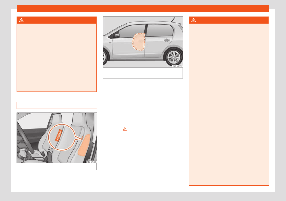
Side airbags
Fig. 17
Side airbag in driver's seat.
Fig. 18 Illustration of completely inflated side
airbag on left side of vehicl
e.
The side airbags are located in the driver's
seat and fr
ont passenger seat backr
ests
›
››
Fig. 17.
The locations are identified by the text “AIR-
BAG” in the upper region of the backrests.
In conjunction with the seat belts, the side air-
bag system provides additional protection for
the upper body in the event of a severe side
collision
›››
.
In a side collision, the side airbags r
educe the
risk of injury t
o passengers t
o the areas of the
body facing the impact. In addition to their
normal protection, the seat belts also hold
the passengers in the event of a side collision;
this is how these airbags provide maximum
protection.
WARNING
●
If you do not wear a seat belt, if you lean
f
orward, or are not seated correctly while
the vehicle is in motion, you are at a greater
risk of injury if the side airbag system is
triggered in an accident.
●
In order for the side airbags to provide
their maximum protection, the prescribed
sitting position must always be maintained
with seat belts fastened while travelling.
●
In a side-on collision the side airbags will
not work if the sensors do not correctly
measure the pressure increase on the inte-
rior of the doors, due to air escaping
through the areas with holes or openings in
the door panel.
●
Never drive if the interior door panels
have been removed or if the panels have
not been correctly fitted.
●
Never drive the vehicle if the loudspeak-
ers in the door panels have been removed,
unless the holes left by the loudspeakers
have been closed properly.
●
Always check that the openings are
closed or covered if loudspeakers or other
equipment are fitted inside the door pan-
els.
●
Occupants of the outer seats must never
carry any objects or pets in the deploy-
ment space between them and the airbags,
or allow children or other passengers to
travel in this position. It is also important
not to attach any accessories (such as cup
24
Airbag system
holders) to the doors. This would impair the
protection off
ered by the side airbags.
●
The built-in coat hooks should be used
only for lightweight clothing. Do not leave
any heavy or sharp-edged objects in the
pockets.
●
Great forces, such as hard blows or kicks,
must not be exerted upon the backrest bol-
ster because the system may be damaged.
In this case, the side airbags would not be
triggered.
●
Under no circumstances should protec-
tive covers be fitted over seats with side
airbags unless the covers have been ap-
proved for use in your vehicle. Because the
airbag deploys from the side of the back-
rest, the use of conventional seat covers
would obstruct the side airbag, seriously
reducing the airbag's effectiveness.
●
Any damage to the original seat uphols-
tery or around the seams of the side airbag
units must be repaired immediately by a
specialised workshop.
●
The airbags provide protection for just
one accident; replace them once they have
deployed.
●
Any work on the side airbag system or re-
moval and installation of the airbag com-
ponents for other repairs (such as removal
of the front seat) should only be performed
by a specialised workshop. Otherwise,
faults may occur during the airbag system
operation.
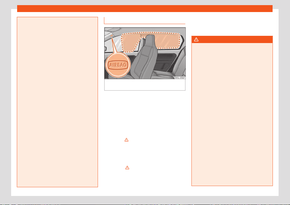
Head-protection airbags*
Fig. 19
Location and deployment area of the
head-pr
ot
ection airbag.
The head-protection airbags are located on
both sides in the int
erior abo
v
e the doors
›››
Fig. 19 and are identified with the text “AIR-
BAG”.
In conjunction with the seat belts, the head-
protection airbag system gives the vehicle
occupants additional protection for the head
and upper body in the event of a severe side
collision
›››
.
The ar
ea fr
amed in r
ed is covered by the
head-protection airbag when it is deployed
›››
Fig. 19 (deployment area). Therefore, ob-
jects should never be placed or mounted in
this area
›››
.
In the e
v
ent of a side collision the curt
ain air-
bag is triggered on the impact side of the ve-
hicle.
The head-protection airbags reduce the risk
of injury to passengers in the front and rear
side seats facing the impact.
WARNING
●
In order for the head-pr
otection airbags
to provide their maximum protection, the
prescribed sitting position must always be
maintained with seat belts fastened while
travelling.
●
For safety reasons, the curtain airbag
must be disabled in those vehicles fitted
with a screen dividing the interior of the ve-
hicle. See your technical service to make
this adjustment.
●
There must be no other persons, animals
or objects between the occupants of the
outer seats and the deployment space of
the head-protection airbags so that the
head-protection airbag can deploy com-
pletely without restriction and provide the
greatest possible protection. Therefore,
sun blinds which have not been expressly
approved for use in your vehicle may not be
attached to the side windows.
●
The built-in coat hooks should be used
only for lightweight clothing. Do not leave
any heavy or sharp-edged objects in the
pockets. Please, do not hang the clothes on
coat hangers.
●
The airbags provide protection for just
one accident; replace them once they have
deployed.
»
25

Safety
●
Any work on the head-prot
ection airbag
system or removal and installation of the
airbag components for other repairs (such
as removal of the roof lining) should only
be performed by a specialised workshop.
Otherwise, faults may occur during the air-
bag system operation.
●
The side and head airbags are managed
through sensors located in the interior of
the front doors. To ensure the correct oper-
ation of the side and curtain airbags nei-
ther the doors nor the door panels should
be modified in any way (e.g. fitting loud-
speakers). If the front door is damaged, the
airbag system may not work correctly. All
work carried out on the front door must be
done in a specialised workshop.
Transporting children
saf
ely
Saf
et
y for children
Introduction
For safety reasons, as we have learned from
accident statistics, we r
ecommend that chil-
dren under 12 years of age travel in the rear
seats. Depending on their age, height and
weight, children travelling in rear seats must
use a child seat or a seat belt. For safety rea-
sons, the child seat should be installed in the
rear seat, behind the front passenger seat or
in the centre back seat.
The physical laws involved and the forces
acting in a collision apply also to children
›››
page 16. But unlike adults, children do not
have fully developed muscle and bone struc-
tures. This means that children are subject to
a greater risk of injury.
To reduce the risk of injuries, children must al-
ways use special child restraint systems
when travelling in the vehicle.
We recommend the use of child safety prod-
ucts from the SEAT Original Accessories Pro-
gramme, which includes systems for all ages
made by “Peke” (not for all countries) (see
www.seat.com).
These systems have been especially de-
signed and approv
ed, complying with the
ECE-R44. regulation.
SEAT recommends securing the child seats
shown on the website as described below:
●
Child seats in the opposite direction of trav-
el (group 0+): ISOFIX and support foot (RÖ-
MER BABY SAFE PLUS SHR II + ISOFIX BASE /
PEKE G0 I-SIZE + I-SIZE BASE).
●
Child seats in the direction of travel (group
1): ISOFIX and Top Tether (RÖMER DUO PLUS
+ TOP TETHER / PEKE G1 TRIFIX I-SIZE).
●
Child seats facing the direction of travel
(group 2): safety belt and ISOFIX (RÖMER
KIDFIX XP).
●
Child seats facing the direction of travel
(group 3): safety belt and ISOFIX (RÖMER
KIDFIX XP).
Follow the manufacturer's instructions and
observe any statutory requirements when in-
stalling and using child seats. Always read
and note
›››
page 28.
We recommend you always carry the manu-
facturer's Child Seat Instruction Manual to-
gether with the on-board documentation.
26
Transporting children safely
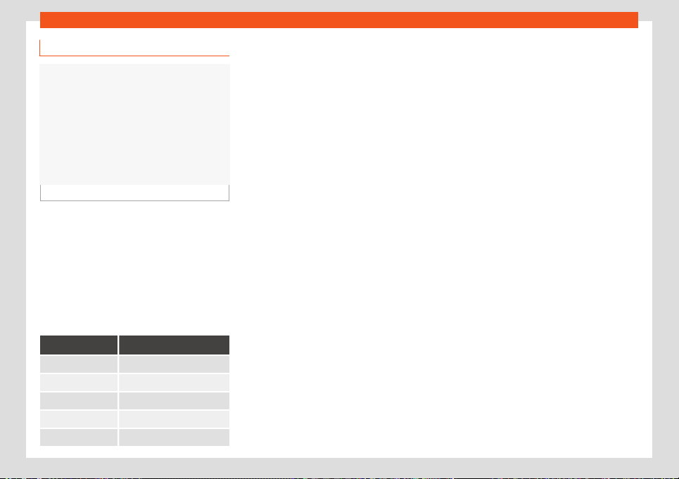
Child seats group classification
Fig. 20
Examples of child seats.
Use only child seats that are officially ap-
pr
o
v
ed and suitable for the child.
Child seats are subject to the regulation ECE-
R 44 or ECE-R 129. ECE-R stands for: Eco-
nomic Commission for Europe Regulation.
Child seats by weight group
The child seats are grouped into 5 catego-
ries:
Age group Weight of the child
Group 0 Up to 10 kg
Group 0+ Up to 13 kg
Group 1 From 9 to 18 kg
Group 2 From 15 to 25 kg
Group 3 From 22 to 36 kg
Child seats that have been tested and ap-
pr
o
v
ed under the ECE-R 44 or ECE-R 129
standard bear the test mark ECE-R 44 or
ECE-R 129 on the seat (the letter E in a circle
with the test number below it).
Follow the manufacturer's instructions and
observe any statutory requirements when in-
stalling and using child seats.
We recommend you to always include the
manufacturer's Child Seat Instruction Manual
together with the on-board documentation.
SEAT recommends you use child seats from
the Original Accessories Catalogue. These
child seats have been designed and tested
for use in SEAT vehicles. You can find the right
child seat for your model and age group at
SEAT dealers.
Child seats by approval category
Child seats may have the approval category
of universal, semi-universal, vehicle specific
(all according to the ECE-R 44 standard) or i-
Size (according to the ECE-R 129 standard).
●
Universal: child seats with universal appro-
val can be installed in all vehicles. There is no
need to consult any list of models. In the case
of universal approval for ISOFIX, the child
seat is additionally provided with a Top Tether
belt.
●
Semi-universal: semi-universal approval,
in addition to the standard requirements of
universal approval, requires safety devices to
lock the child seat, which require additional
testing. Child seats with semi-universal ap-
proval include a list of vehicle models for
which they can be installed.
●
Vehicle-specific: vehicle-specific approval
requires a dynamic test of the child seat for
each vehicle model separately. Child seats
with vehicle-specific approval also include a
list of vehicle models for which they can be
installed.
●
i-Size: child seats with i-Size approval must
meet the requirements prescribed in the ECE-
R 129 standard in relation to installation and
safety. Child seat manufacturers can tell you
which seats have i-Size approval for this vehi-
cle.
27
Safety
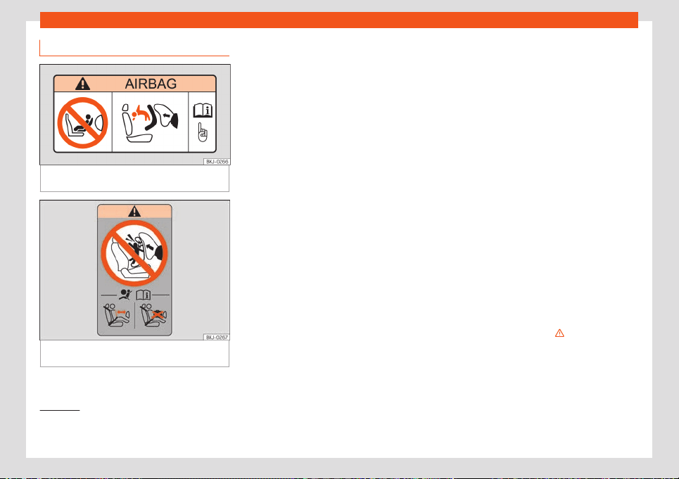
Fitting and using child seats
Fig. 21 Airbag sticker: on the passenger’s sun
visor
Fig. 22 Airbag sticker: on the rear frame of the
passenger side door
Warnings about fitting a child seat
T
ak
e the f
ollowing general warnings into ac-
count if you are going to fit a child seat. They
are valid for all child seats regardless of their
attachment system.
●
Please read and follow the child seat man-
ufacturer's operating instructions.
●
The child seat should preferably be fitted to
the rear seat behind the front passenger seat
so that the child can exit the vehicle on the
pavement side.
●
Set the height of the seat belt such that it
adapts to the child seat naturally, without
twisting. The lowest position of the seat belt
height regulator must be used with rear-fac-
ing child seats.
●
To correctly use a child seat in the back,
the front backrest must be adjusted so that
there is no contact with the child seat in the
back in the case that it goes opposite to the
direction of the car. In the case of front facing
restraint systems, the front backrest must be
adjusted so that there is no contact with the
child's feet.
●
If a semi-universal type chair is to be instal-
led, in which the method of attachment to the
car is through the seat belt and support
bracket, it should never be installed in the
central rear seat as the ground clearance is
lower than in other places and the support
bracket will not allow the seat to remain suffi-
ciently stable.
●
When fitting a child seat on the front pas-
senger seat, the seat must be moved back-
wards as far as possible and placed in the
highest position. The backrest must also be
put in a vertical position
1)
.
Important information about the front pas-
senger front airbag
A sticker with important information about the
passenger airbag is located on the passeng-
er's sun visor and/or on the passenger side
door frame
›››
Fig. 21.
Read and always observe the safety informa-
tion included in the following chapters:
●
Safety distance with respect to the passen-
ger airbag
›››
page 20.
●
Objects between the passenger and the
passenger side airbag
›››
in Front airbags
on page 23.
The passenger side fr
ont airbag, when ena-
bl
ed, is a serious risk f
or a child that is facing
backward since the airbag can strike the seat
1)
Compliance with current national legislation
and the manufactur
er's instructions is required
when using or installing child seats.
28

Transporting children safely
with such force that it can cause serious or
f
at
al injuries. Chil
dren up to 12 years old
should always travel on the rear seat.
Therefore we strongly recommend you to
transport children on the rear seats. This is
the safest location in the vehicle. Alternative-
ly, the front passenger airbag can be disa-
bled with a key-operated switch
›››
page 23.
When transporting children, use a child seat
suitable for the age and size of each child
›››
page 27.
WARNING
●
If a child seat is secured t
o the front pas-
senger seat, the risk to the child of sustain-
ing critical or fatal injuries in the event of an
accident increases.
●
An inflating front passenger airbag can
strike the rear-facing child seat and project
it with great force against the door, the roof
or the backrest.
●
Never install a child seat facing back-
wards on the front passenger seat unless
the front passenger front airbag has been
disabled. Risk of potentially fatal injuries to
the child! However, if necessary, the front
passenger front airbag must be deactiva-
ted
›››
page 23. If the passenger seat has a
height adjustment option, move it to the
highest, most upright position. If you have a
fixed seat, do not install any child restraint
system in this location.
●
For those vehicl
es that do not include a
key lock switch to deactivate the airbag,
the vehicle must be taken to a technical
service. Do not forget to reconnect the air-
bag when an adult wants to sit in the front
passenger seat.
●
Never allow a child to be transported in a
vehicle without being properly secured, or
to stand up or kneel on a seat while travel-
ling. In an accident, the child could be flung
through the vehicle, causing possibly fatal
injuries to themselves and to the other vehi-
cle occupants.
●
Never leave a child alone in the child seat
or in the vehicle.
●
Children who are less than 1.5 metres tall
must not wear a normal seat belt without a
child seat, as this could cause injuries to
the abdominal and neck areas during a
sudden braking manoeuvre or in an acci-
dent.
●
When a child seat is mounted in the rear
seats, the door child-proof lock should be
activated
›››
page 73.
Attachment systems
Depending on the country, different attach-
ment syst
ems ar
e used f
or safely installing
child seats.
Attachment systems overview
●
ISOFIX: ISOFIX is a standardised attach-
ment system allowing quick and safe attach-
ment of child seats in the vehicle. ISOFIX at-
tachment establishes a rigid connection be-
tween the child seat and the car body.
The child seat has two rigid attachment clips,
called connectors. These connectors are fit-
ted into the ISOFIX attachment rings found
between the seat cushion and the backrest
of the vehicle's back seat (on the sides). ISO-
FIX attachment systems are used mainly in
Europe
›››
page 30. If necessary, ISOFIX at-
tachment may have to be supplemented with
a Top Tether belt or a support bracket.
●
Automatic three-point seat belt. When-
ever possible, it is preferable to attach the
child seats with the ISOFIX system rather than
attaching them with an automatic three-point
seat belt
›››
page 33.
Additional attachment:
●
Top Tether: the Top Tether belt is guided
over the back of the rear seat and attached
to an anchor point with a hook. Anchor points
are located at the back of the rear seat back-
rest on the boot side
›››
page 32. The rings
for retaining the Top Tether belt are marked
with an anchor symbol.
●
Support bracket: some child seats rest on
the floor of the vehicle with a support bracket.
The support bracket prevents the child seat
»
29
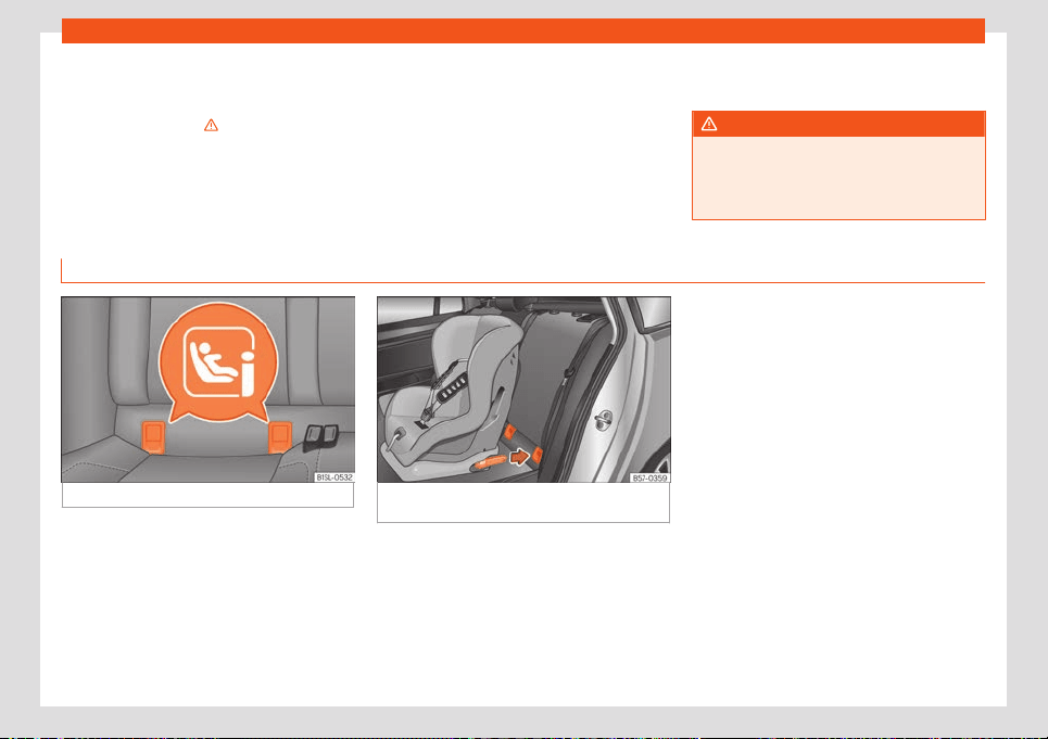
Safety
from tipping forward in the event of impact.
Chil
d seats fitt
ed with a support br
acket
should only be used in the passenger seat
and side rear seats
›››
. For the assembly of
this t
ype of seat you shoul
d al
so consult the
list of approved vehicles for this assembly,
available in the instructions for child restraint
systems.
Recommended systems for attaching
child seats
SEAT recommends attaching child seats as
follows:
●
Baby carriers or child seats in the oppo-
site direction of travel: ISOFIX and support
bracket or i-Size.
●
Child seats in the direction of travel: ISO-
FIX and Top Tether.
WARNING
Incorrect use of the support bracket can
cause serious or fatal injury.
●
Mak
e sure the support bracket is correct-
ly and safely installed.
Fit a child seat with the ISOFIX / i-Size and Top Tether* system
Fig. 23 Rear seat: ISOFIX/i-Size securing rings.
Fig. 24 Rear seats: fitting a child seat with the
ISOFIX system.
Child seats can be secured quickly, easily
and saf
ely on the r
ear seats with the ISOFIX/i-
Siz
e * and Top Tether system.
Two “ISOFIX” retaining rings are fitted on each
rear side seat. The “ISOFIX” rings are located
between the rear seat backrest and the seat
cushioning
›››
Fig. 23. The Top Tether* rings
are located on the rear part of the backrests
of the rear seats (behind the seat backrest or
in the boot)
›››
page 32.
To understand the compatibility of the ISO-
FIX/i-Size systems in the vehicle, check the ta-
ble below.
30

Transporting children safely
Age group Class according to size
a)
Front passenger seat Rear seats
Group 0: up to 10 kg E X IL
-SU
Group 0+: up to 13 kg
E X
IL
-SUD X
C X
Group 1: 9 to 18 kg
D X
IL-SU
IUF
C X
B X
B1 X
A X
Gr
oup 2: 15 to 25 kg – X IL
-SU
Group 3: 22 to 36 kg – X IL-SU
i-Size child restraint system – X i-U
X: space not suitable for fixing an ISOFIX or i-Size child seat in this group.
IL-SU: space suitable for installing an ISOFIX child seat with semi-universal approval. Take the child seat manufacturer's vehicle list into account.
IUF: suitable place for installing an ISOFIX child seat with universal approval.
i-U: space suitable for fitting a forward- or rear-facing i-Size child seat with universal approval.
i-UF: space suitable for fitting a forward-facing i-Size child seat with universal approval.
a)
The indication of class according to size corresponds to the authorised bodyweight for the child seat. In child seats with universal or semi-universal approval, the class
accor
ding t
o siz
e is indicated on the ECE approval label. The indication of class according to size is stated on the corresponding child seat.
Securing the child seat with the “ISOFIX/i-
Size” system
You are obliged to follow the seat manufac-
turer's instructions.
●
Press the child seat onto the “ISOFIX/iSize”
retaining rings until the child seat is heard to
engage securely
›››
Fig. 24. If the child seat is
equipped with Top Tether* anchor points, se-
cure it to the correspondent ring
›››
page 32.
Observe the manufacturer's instructions.
●
Pull on both sides of the child seat to ensure
that it is properly anchored.
Child seats with the “ISOFIX” and Top Tether*
attachment system are available from Tech-
nical Services.
»
31
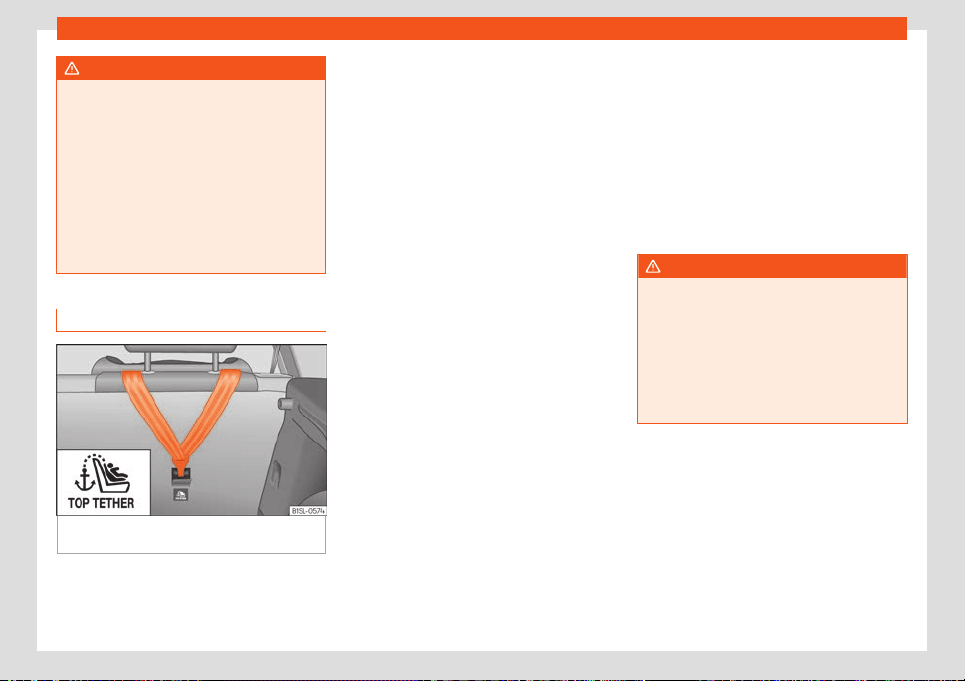
Safety
WARNING
The retaining rings are designed only for
use with “ISOFIX” and Top Tether* syst
em
child seats.
●
Never secure other child seats that do
not have the “ISOFIX” or Top Tether* sys-
tem, or retaining belts or objects to the fas-
tening rings - this can result in potentially
fatal injuries to the child.
●
Ensure that the child seat is secured cor-
rectly using the “ISOFIX” and Top Tether*
securing rings.
Top Tether* securing belts
Fig. 25
Back of the rear seats: Top Tether ring
conceal
ed underneath a cut in the carpet.
Child seats with the Top Tether system come
with a str
ap f
or securing the seat t
o the vehi-
cle anchor point, located at the back of the
rear seat backrest and provide greater re-
straint.
The objective of this strap is to reduce for-
ward movements of the child seat in a crash,
to reduce the risk of injuries to the head from
hitting the inside of the vehicle.
Using the Top Tether in rear-facing moun-
ted seats
Currently, there are very few rear-facing child
safety seats that have Top Tether. Please
carefully read and follow the seat manufac-
turer instructions to learn the proper way to
install the Top Tether strap.
Securing the retainer strap
●
Follow the manufacturer's instructions to
deploy the child seat Top Tether retaining
strap.
●
Place the belt under the headrest of the
back seat (depending on the instructions of
the chair itself, lift or remove the headrest if
necessary).
●
Slide the strap and secure it properly with
the anchorage of the backrest
›››
Fig. 25.
●
Firmly tighten the strap following the manu-
facturer's instructions.
Releasing the retaining strap
●
Loosen the strap following the manufactur-
er's instructions.
●
Push the lock and release it from the an-
choring support.
WARNING
An undue installation of the safety seat will
increase the risk of injury in the ev
ent of a
crash.
●
Never tie the retainer strap to a hook in
the luggage compartment.
●
Never secure or tie luggage or other
items to the lower anchorages (ISOFIX) or
the upper ones (Top Tether).
32
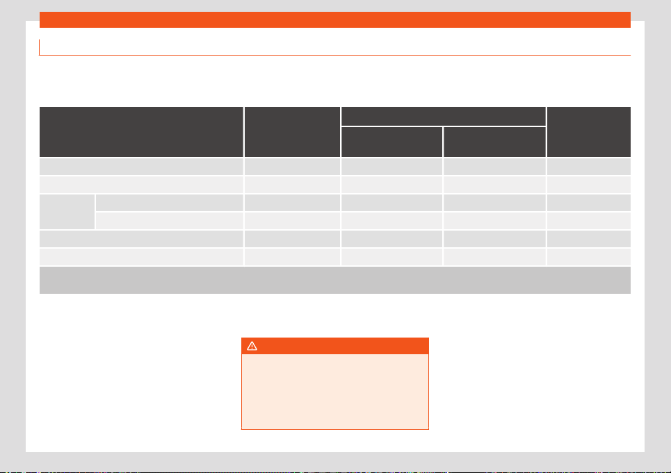
Transporting children safely
Fitting a child seat using the seat belt
If you want to fit a universal approval catego-
ry (U) child seat in your vehicl
e, you must
check that the seat is approved for your vehi-
cle. You will find any necessary information
on the child seat’s orange ECE approval la-
bel. The following table shows the different
fitting options.
Age group Weight of the child
Front passenger seat
Rear seats
Front passenger air-
bag activated
Front passenger air-
bag deactivated
Group 0 Up to 10 kg X U U
Group 0+ Up to 13 kg X U U
Group 1
Rear-facing From 9 to 18 kg X U U
Forward-facing From 9 to 18 kg U X U
Group 2 From 15 to 25 kg U X U
Group 3 From 22 to 36 kg U X U
U: univ
ersal.
X:
vehicle seat unsuitable for fitting this group of child seat.
Fitting a child seat using the seat belt
●
Set the height of the seat belt such that it
adapts t
o the chil
d seat nat
urally, without
twisting. The lowest position of the seat belt
height regulator must be used with rear-fac-
ing child seats.
●
Put the seat belt in place and pass it
through the child seat according to the in-
structions of the child seat manufacturer.
●
Make sure that the seat belt is not twisted.
●
Insert the latch plate into the seat's buckle
until you hear the engagement click.
WARNING
When travelling, children must be secured
in the vehicle with a r
estraint system suita-
ble for age, weight and size.
●
Read and always observe information
and warnings concerning the use of child
seats
›››
page 28.
33
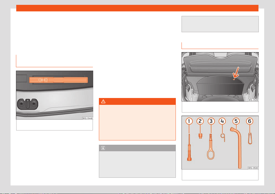
Emergencies
Emergencies
Self
-help
Emer
gency equipment
First aid kit, w
arning triangle and
fire extinguishers*
Fig. 26
In the luggage compartment: warning
triangl
e
.
Warning triangle
The use of r
efl
ectiv
e warning triangles is
obligatory in emergencies in some countries.
As are the first aid kit and a set of spare light
bulbs.
Depending on the vehicle’s equipment, the
warning triangle can be found in a compart-
ment located under the floor panel of the
load area in the luggage compartment
›››
Fig. 26.
First aid kit
The first aid kit must comply with legal re-
quirements. Check the expiry date of the
contents of the first aid kit.
Fire extinguisher
A fire extinguisher can be stored in a holder in
the passenger seat footwell.
The fire extinguisher must conform to legal
requirements, be ready for use and be
checked regularly. Check the certification
seal on the extinguisher.
WARNING
Loose objects in the vehicle interior can be
violently thro
wn in case of a sudden ma-
noeuvre or braking and especially in acci-
dents causing serious injury.
●
Secure or store fire extinguishers, first aid
kit, reflective vests and warning triangle
securely in the vehicle.
Note
●
The first aid kit, warning triangle
, reflec-
tive vests and fire extinguishers are not part
of the vehicle's standard equipment.
●
The warning triangle should meet legal
requirements.
●
Before acquiring accessories and emer
-
gency equipment see the instructions in
“Accessories and spares”
›››
page 202.
Vehicle tool kit
Fig. 27
In the luggage compartment: carpet
r
aised.
Fig. 28 Underneath the floor panel of the lug-
gage compartment: v
ehicl
e t
ool kit.
34
Self-help
The vehicle tool kit is located under the floor
panel in the luggage compartment
›
›
›
Fig. 27.
To access the vehicle tools
›››
page 90.
The tool kit includes:
Screwdriver with hexagon socket in the
handle for screwing and unscrewing the
wheel nuts
Adapter for the anti-theft bolt
Towing eye, removable
Hook for extracting the central wheel
trims*
Wheel spanner
Clip for removing the wheel bolt caps
Some of the items listed are only provided in
certain model versions, or are optional extras.
WARNING
If loose, the vehicle tool kit and anti-punc-
ture kit coul
d be thrown violently in the
passenger compartment in case of sudden
manoeuvres, sudden braking and acci-
dents, and could cause serious injuries.
●
Always check that the vehicle tool kit and
the anti-puncture kit are securely fastened
in the luggage compartment.
WARNING
Unsuitable or damaged vehicle tools can
cause injury or accidents.
1
2
3
4
5
6
●
Never w
ork with inappropriate or dam-
aged tools.
Tyre repairs
TMS (Tyr
e Mobility System)*
The Anti-puncture kit * (Tyre Mobility System)
will reliably seal punctur
es caused by the
penetration of a foreign body of up to about
4 mm in diameter. Do not remove foreign
objects, e.g. screws or nails, from the tyre.
After inserting the sealant residue in the tyre,
you must again check the tyre pressure
about 10 minutes after starting the engine.
You should only use the tyre mobility set if the
vehicle is parked in a safe place, you are fa-
miliar with the procedure and you have the
necessary tyre mobility set! Otherwise, you
should seek professional assistance.
Do not use the tyre sealant in the following
cases:
●
If the wheel rim has been damaged.
●
In outside temperatures below -20°C
(-4°F).
●
In the event of cuts or perforations in the
tyre gr
eater than 4 mm.
●
If you have been driving with very low pres-
sure or a completely flat tyre.
●
If the sealant bottle has passed its use by
date.
WARNING
Using the tyre mobility system can be dan-
gerous, especially when filling the tyr
e at
the roadside. Please observe the following
rules to minimise the risk of injury:
●
Stop the vehicle safely as soon as possi-
ble. Park it at a safe distance from sur-
rounding traffic to fill the tyre.
●
Ensure the ground on which you park is
flat and solid.
●
All passengers and particularly children
must keep a safe distance from the work
area.
●
Turn on the hazard warning lights to warn
other road users.
●
Use the tyre mobility system only if you
are familiar with the necessary procedures.
Otherwise, you should seek professional
assistance.
●
The tyre mobility set is intended for tem-
porary emergency use only until you can
reach the nearest specialised workshop.
●
Replace the repaired tyre with the tyre
mobility set as soon as possible.
●
The sealant is a health hazard and must
be cleaned immediately if it comes into
contact with the skin.
●
Always keep the tyre mobility set out of
the reach of small children.
»
35
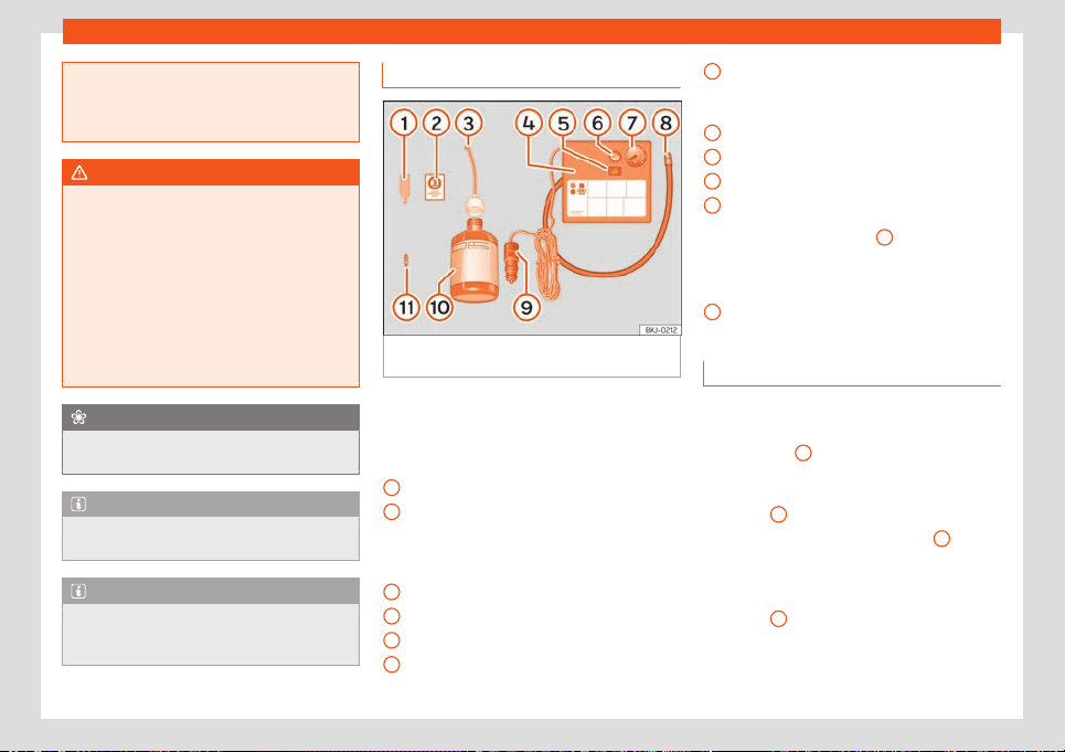
Emergencies
●
Always st
op the engine, apply the hand
brake and put it in gear when using a man-
ual gearbox, in order to reduce the risk of
involuntary movement of the vehicle.
WARNING
A tyre filled with sealant does not have the
same perf
ormance proper
ties as a conven-
tional tyre.
●
Never drive faster than 80 km/h
(50 mph).
●
Avoid heavy acceleration, hard braking
and fast cornering.
●
Drive for only 10 minutes at a maximum
speed of 80 km/h (50 mph) and then check
the tyre.
For the sake of the environment
Dispose of used or expired sealant observ-
ing any legal requir
ements.
Note
A new bottle of sealant can be purchased
at SEAT dealerships.
Note
Take into account the separate instruction
manual of the tyre mobilit
y set * manufac-
turer.
Anti-puncture kit contents*
Fig. 29
Standard representation: anti-punc-
t
ur
e kit cont
ents.
The anti-puncture kit is located underneath
the fl
oor co
v
ering in the luggage compart-
ment. It includes the following components
›››
Fig. 29:
Valve insert remover
A sticker to be adhered to the instrument
cluster, within the driver's visual field, to
remind that the maximum advisable
speed “max. 80 km/h” or “max. 50 mph”
Filler tube with cap
Air compressor
ON/OFF switch
Air bleed screw (it can also be integrated
in the inflator tube).
1
2
3
4
5
6
Warning provided by tyre pressure moni-
t
oring syst
em (it can al
so be integrated in
the inflator tube).
Tube for inflating tyres
12 volt connector
Bottle of sealant
Spare tyre valve
The valve insert remover
1
has a gap at
the l
o
w
er end for a valve insert. The valve in-
sert can only be screwed or unscrewed in this
way. This also applies to its replacement part
11
.
Sealing and inflating a tyre
Sealing the tyre
●
Unscrew the tyre valve cap and insert. Use
the
›
›
›
Fig. 29
1
tool to remove the insert.
Pl
ace it on a cl
ean surf
ace.
●
Shake the tyre sealant bottle vigorously
›››
Fig. 29
10
.
●
Screw the inflator tube
›
›
›
Fig. 29
3
into
the seal
ant bottl
e
. The bottle's seal will break
automatically.
●
Remove the lid from the filling tube
›››
Fig. 29
3
and screw the open end of the
t
ube int
o the t
yre valve.
●
With the bottle upside down, empty all of
the contents into the tyre.
7
8
9
10
11
36
Self-help
●
R
emo
v
e the bottle from the valve.
●
Place the insert back into the tyre valve us-
ing the tool
›››
Fig. 29
1
.
Infl
ating the t
yr
e
●
Screw the compressor tyre inflator tube
›››
Fig. 29
8
into the tyre valve.
●
Check that the air bleed screw is closed
›
›
›
Fig. 29
6
.
●
Connect the vehicle's drive system.
●
Insert the connector
›
›
›
Fig. 29
9
into the
v
ehicl
e's 12-v
olt socket
›››
page 97.
●
Turn the air compressor on with the
ON/OFF switch
›››
Fig. 29
5
.
●
Keep the air compressor running until it rea-
ches 2.
0 t
o 2.5 bar (29-36 psi/200-250 kP
a).
A maximum of 8 minutes.
●
Disconnect the air compressor.
●
If it does not reach the pressure indicated,
unscrew the tyre inflator tube from the valve.
●
Move the vehicle 10m so that the sealant is
distributed throughout the tyre.
●
Screw the compressor tyre inflator into the
valve.
●
Repeat the inflation process.
●
If the indicated pressure still cannot be
reached, the tyre is too badly damaged. Stop
and request assistance from an authorised
technician.
●
Disconnect the air compressor. Unscrew
the tyre inflator tube from the tyre valve.
●
When the tyre pressure is between 2.5 and
2.0 bars, continue driving without exceeding
80 km/h (50 mph).
●
Attach the sticker
›››
Fig. 29
2
to the in-
strument clust
er
, within the driv
er's visual
field.
●
Check the pressure again after 10 minutes
›››
page 37.
WARNING
When inflating the wheel, the air compres-
sor and the inflator t
ube may become hot.
●
Protect hands and skin from hot parts.
●
Do not place the hot flexible inflator tube
or hot air compressor on flammable mate-
rial.
●
Allow them to cool before storing the de-
vice.
●
If it is not possible to inflate the tyre to at
least 2.0 bars (29 psi / 200 kPa), the tyre is
too badly damaged. The sealant is not in a
good condition to seal the tyre. Do not con-
tinue driving. Seek specialist assistance.
CAUTION
Switch off the air compressor after a maxi-
mum of 8 operational minutes t
o avoid
overheating! Before switching on the air
compressor again, let it cool for several mi-
nutes.
Check after 10 minutes of driving
Screw the inflator tube
›››
Fig. 29
5
again
and check the pressure on the gauge
6
.
1.3 bar (19 psi / 130 kPa) and lo
wer:
●
Stop the vehicle! The tyre cannot be
sealed sufficiently with the tyre mobility set.
●
You should obtain professional assistance
›››
.
1.4 bar (20 psi / 140 kPa) and higher:
●
Set the tyr
e pressure to the correct value
again.
●
Carefully resume your journey until you
reach the nearest specialised w
orkshop with-
out exceeding 80 km/h (50 mph).
●
Have the damaged tyre replaced.
WARNING
Driving with an unsealed tyre is dangerous
and can cause accidents and serious in-
jury.
●
Do not continue driving if the tyre pres-
sure is 1.3 bar (19 psi / 130 kPa) and l
ower.
●
Seek specialist assistance.
37
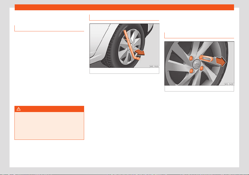
Emergencies
Changing a wheel
What t
o do first
●
Park the vehicle on a horizontal surface and
in a safe place as f
ar away from traffic as
possible.
●
Apply the handbrake.
●
Switch on the hazard warning lights.
●
Position the selector lever in N or P.
●
Keep the vehicle tool kit
›››
page 34 and
the spare wheel* available.
●
Observe the applicable legislation for each
country (reflective vest, warning triangles,
etc.).
●
All occupants should leave the vehicle and
wait in a safe place (for instance behind the
roadside crash barrier).
WARNING
●
Always observ
e the above steps and pro-
tect yourself and other road users.
●
If you change the wheel on a slope, block
the wheel on the opposite side of the car
with a stone or similar to prevent the vehi-
cle from moving.
Integral wheel trim
Fig. 30
Remove the wheel cover.
The wheel covers must be removed for ac-
cess t
o the wheel bolts.
R
emo
ving
●
Take the wheel brace and the wire hook
from the vehicle tool kit
›››
page 34.
●
Hook the wire through one of the grooves of
the trim.
●
Insert the box spanner through the hook,
rest it on the tyre and remove the wheel trim
›››
Fig. 30.
Fitting
●
Press the trim against the wheel so that the
hole for the valve fits over the tyre valve.
●
Make sure that the trim is correctly fitted all
the way around the wheel. If you are using an
anti-theft wheel lock, screw it in the opposite
position to the valve.
Wheel bolt caps*
Fig. 31 Wheel: wheel nuts with caps.
Removal
●
Fit the plastic clip (vehicle tools
›
›
›
Fig. 28)
over the cap until it clicks into place
›››
Fig. 31.
●
Remove the cap with the plastic clip.
The caps protect the wheel bolts and should
be remounted after changing the tyre.
The anti-theft wheel locking bolt has a
special cap. This only fits on anti-theft locking
bolts and is not for use with standard wheel
bolts.
38
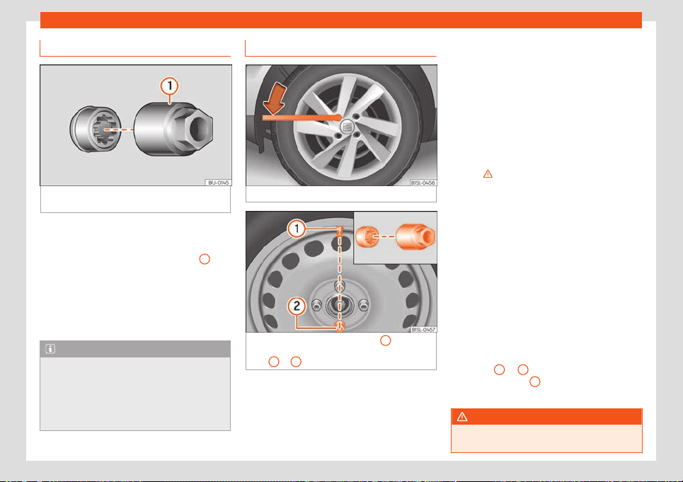
Self-help
Anti-theft wheel nuts
Fig. 32
Anti-theft wheel bolt with cap and
adapt
er
.
Loosening the anti-theft wheel bolt
●
Remove the wheel cover* or the cap*.
●
Insert the special adapter
›
›
›
Fig. 32
1
(ve-
hicl
e t
ool
s
›››
page 34) onto the anti-theft
wheel bolt and push it on as far as it will go.
●
Insert the wheel brace (vehicle tools) onto
the adapter as far as it will go.
●
Remove the wheel bolt
›››
page 39.
Note
Make a note of the code number of the an-
ti-theft wheel bolt and keep it in a safe
pl
ace, but not in your vehicle. If you need a
new adapter, you can obtain it from the
SEAT Official Service, indicating the code
number.
Loosening wheel bolts
Fig. 33
Wheel change: loosen the wheel nuts.
Fig. 34
Wheel change: tyre valve
1
and the
corr
ect position f
or the anti-theft wheel l
ocking
bolt
2
or
3
.
Use only the wheel wrench belonging to the
car t
o l
oosen the wheel bolts.
L
oosen the wheel bolts only about one turn
before raising the vehicle with the jack.
If the wheel bolt is very tight, carefully push
on the end of the wheel wrench with your
foot. Hold on to the vehicle for support and
take care not to slip during this operation.
Loosening wheel bolts
●
Fit the wheel wrench on as far as it will go
›››
Fig. 33.
●
Hold the wrench at the end and rotate the
bolt approximately one turn anticlock-
wise
›››
.
Impor
t
ant inf
ormation about wheel bolts
Factory-fitted rims and wheel bolts are spe-
cially matched during construction. There-
fore, if different rims are fitted, the correct
wheel bolts with the right length and heads
must be used. This ensures that wheels are
fitted securely and that the brake system
functions correctly.
In certain circumstances, you should not even
use wheel bolts from vehicles of the same
model.
In wheels with full hubcaps, the anti-theft
locking bolt must be threaded onto positions
›››
Fig. 34
2
or
3
, taking the tyre valve’s po-
sition as r
ef
er
ence
1
. Otherwise it will not be
possibl
e t
o mount the hubcap
.
WARNING
If the wheel bolts are not properly tight-
ened, they could come loose whil
e driving
»
39
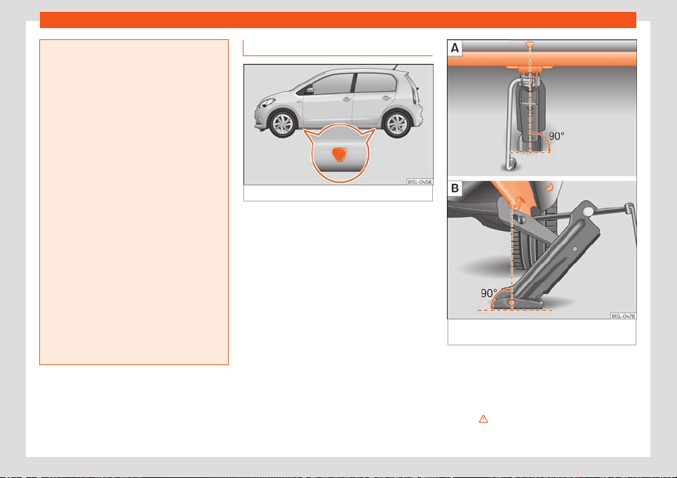
Emergencies
and cause an accident, serious injury and
loss of vehicl
e control.
●
Use only wheel bolts which correspond
to the rim in question.
●
Never use different wheel bolts.
●
Wheel bolts and threads should be clean,
free of oil and grease, and it should be pos-
sible to screw them easily.
●
To loosen and tighten wheel bolts, only
use the wheel wrench that came with the
car from the factory.
●
The wheel bolts should only be loosened
slightly (about one turn) before raising the
vehicle with the jack. Risk of accident!
●
Never apply grease or oil to wheel bolts
or to the wheel hub threads. Even if the
bolts have been tightened to the prescri-
bed torque, they could come loose while
driving.
●
Never loosen the screwed joints of wheel
rims with bolted ring trims.
●
If wheel bolts are tightened below the
prescribed torque, the bolts and rims could
come loose while driving. If tightening tor-
que is too high, the wheel bolts or threads
can be damaged.
Raise the vehicle
Fig. 35
Jack position points.
Fig. 36 Cross member: positioning the jack on
the v
ehicl
e
.
●
Rest the jack (vehicles tools) on firm
gr
ound. If necessary use a l
ar
ge, strong
board or similar support. If the surface is slip-
pery (for example tiles) place the jack on a
rubber mat or similar to prevent it from slip-
ping
›››
.
40
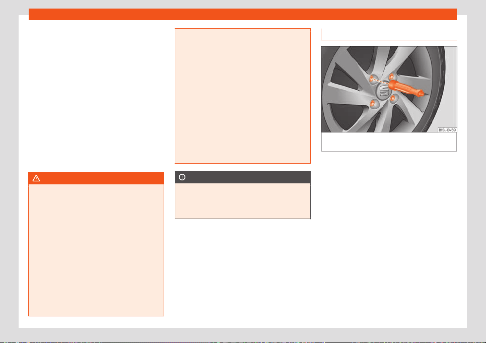
Self-help
●
Find the support point on the strut (sunk
en
ar
ea) cl
osest to the wheel to be changed
›››
Fig. 35.
●
Raise the jack with the crank handle until it
can be inserted just below the support point
of the vehicle.
●
Make sure that the base of the jack rests
firmly on the ground and that it is exactly be-
low the vertical support point
›››
Fig. 36.
●
Centre the jack and continue to raise it us-
ing the crank handle until the claw grasps the
reinforcement located under the vehicle
›››
Fig. 36.
●
Keep raising the jack until the wheel comes
slightly off the ground.
WARNING
The factory-supplied jack is only designed
for changing wheels on this model. On no
account att
empt to use it for lifting heavier
vehicles or other loads. Risk of injury.
●
Make sure the jack remains stable. If the
surface is slippery or soft, the jack could
slip or sink, respectively, with the conse-
quent risk of causing injuries.
●
Lift the vehicle using only the jack sup-
plied from the factory. Other jacks, even
those approved for other SEAT models
could slip, with the consequent risk of in-
jury.
●
Place the jack only at the support points
provided on the strut and align it. Other-
wise, the jack could slip because it does
not have sufficient grip on the vehicl
e: risk
of injury!
●
You should never place a body limb such
as an arm or leg under a raised vehicle that
is solely supported by the jack.
●
If you have to work underneath the vehi-
cle, you must use suitable stands addition-
ally to support the vehicle, there is a risk of
accident!.
●
Never raise the vehicle if it is tilting to one
side or the engine is running.
●
Never start the engine when the vehicle is
raised. The vehicle may come loose from
the jack due to the engine vibrations.
CAUTION
The vehicle must not be raised on the
crossbar. Pl
ace the jack only at the support
points provided on the strut and align it.
Otherwise, the vehicle may be damaged.
Removing and installing a wheel
Fig. 37
Wheel change: loosen wheel nuts us-
ing the sock
et in the handl
e of the scr
ewdriver.
Change the wheel after loosening the wheel
bolts and r
aising the v
ehicl
e with the jack.
When removing/fitting the wheel, the rim may
hit and damage the brake disc. For this rea-
son, please take care and get a second per-
son to assist you.
Taking off the wheel
●
Using the hexagonal socket in the wheel
brace
›››
Fig. 37, unscrew the slackened
wheel bolts and place them on a clean sur-
face.
●
Take off the wheel.
Putting on the spare wheel
Check the direction of rotation of the tyre
›››
page 42.
»
41
Emergencies
●
Pl
ace the spar
e wheel or t
emporary spare
wheel into position.
●
Replace the wheel bolts and tighten slight-
ly using the hexagonal socket on the end of
the wheel brace.
●
To tighten the anti-theft locking wheel bolts
use the corresponding adaptor.
●
Carefully lower the vehicle using the jack.
●
Use the wheel spanner to tighten all of the
wheel nuts clockwise. Tighten the bolts in di-
agonal pairs (not in a circle).
●
Put the caps or full hubcap back on.
The wheel bolts should be clean and turn
easily. Before fitting the spare wheel, inspect
the wheel condition and hub mounting surfa-
ces. These surfaces must be clean before fit-
ting the wheel.
Tightening torque of the wheel nuts
The prescribed tightening torque for wheel
bolts for steel and alloy wheels is 110 Nm. Af-
ter changing a wheel, have the tightening tor-
que checked immediately with a torque
wrench that is working perfectly.
Before checking tightening torque, have any
rusty wheel bolts that are difficult to screw re-
placed and clean the wheel hub threads.
Never apply grease or oil to wheel bolts or to
the wheel hub threads. Even if the bolts have
been tightened to the prescribed torque, they
could come loose while driving.
WARNING
The hexagonal socket in the wheel brace
should be used for t
urning wheel bolts only.
Do not use it to loosen or tighten the wheel
bolts.
Tyres with directional tread pattern
Tyres with directional tread pattern have
been designed t
o oper
at
e best when rotating
in only one direction. An arrow on the tyre
sidewall indicates the direction of rotation on
tyres with directional tread. Always observe
the indicated direction of rotation in order to
guarantee optimum grip and help avoid
aquaplaning, excessive noise and wear.
If the tyre is mounted in the opposite direction
of rotation, drive with extreme caution, as the
tyre is no longer being used correctly. This is
of particular importance when the road sur-
face is wet. Change the tyre as soon as pos-
sible or remount it with the correct direction
of rotation.
Works after changing a wheel
●
Alloy wheels: r
epl
ace the wheel bolt caps.
●
Pl
ate wheels: replace the wheel hubcap .
●
Return all tools to their proper storing loca-
tion.
●
If the replaced wheel does not fit in the
spare wheel housing, store it safely in the lug-
gage compartment
›››
page 89.
●
Check the tyre pressure of the newly moun-
ted tyre as soon as possible.
●
In vehicles fitted with a tyre pressure indica-
tor, adjust the pressure and store it in memory
›››
page 192.
●
Have the tightening torque of the wheel
nuts checked as soon as possible with a tor-
que wrench
›››
page 42. Meanwhile, drive
carefully.
●
Have the flat tyre replaced as quickly as
possible.
42
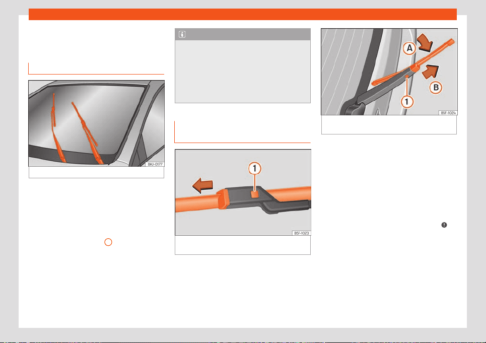
Self-help
Changing the windscreen
wiper bl
ades
Wiper service position
Fig. 38
Wipers in service position.
The wiper arms can be raised when the wip-
ers ar
e in service position
›
›
›
Fig. 38.
●
Close the bonnet
›››
page 176.
●
Switch the ignition on and off.
●
Press the windscreen wiper lever down-
wards briefly
›››
page 82
4
.
Bef
or
e driving, al
ways lower the wiper arms.
Using the windscreen wiper lever, the wind-
screen wiper arms return to their initial posi-
tion.
Note
●
The windscreen wiper arms can be
mov
ed to the service position only when
the bonnet is properly closed.
●
You can also use the service position, for
example, if you want to fix a cover over the
windscreen in the winter to keep it clear of
ice.
Changing the wiper rear wiper
blades
Fig. 39 Changing the windscreen wiper
bl
ades
Fig. 40 Removing and fitting the rear window
wiper blade.
The windscreen wiper blades are supplied as
st
andar
d with a l
ayer of graphite. This layer is
responsible for ensuring that the wipe is silent.
If the graphite layer is damaged, the noise of
the water as it is wiped across the windscreen
will be louder.
Check the condition of the wiper blades reg-
ularly. If the wipers scrape across the
glass, they should be changed if they are
damaged, or cleaned if they are dirty
›››
.
If this does not pr
oduce the desir
ed r
esults,
the setting angle of the windscreen wiper
arms might be incorrect. They should be
checked by a specialised workshop and cor-
rected if necessary.
Damaged windscreen wiper blades should
be replaced immediately. These are availa-
ble from qualified workshops.
»
43
Emergencies
Raising and lowering windscreen wiper
arms
●
Place the windscreen wipers in the service
position
›
›
›
page 43.
●
Grip the wiper arms only by the blade's
fastening point.
Cleaning windscreen wiper blades
●
Raise the wiper arms.
●
Use a soft cloth to remove dust and dirt
from the windscreen wiper blades.
●
If the blades are very dirty, a sponge or
damp cloth may be used
›››
.
Changing the windscr
een wiper bl
ades
●
Lift and unf
old the wiper arms.
●
Press and hold release button
›››
Fig. 39
1
and pull gently on the wiper blade in the di-
r
ection of the arr
o
w.
●
Fit a new wiper blade of the same length
and design on to the wiper arm and hook it
into place.
●
Rest the wiper arms back onto the wind-
screen.
Changing the rear wiper blade
●
Lift and fold the wiper arm.
●
Turn the blade slightly
›››
Fig. 40 (arrow
A
).
●
Hol
d do
wn the r
elease button
1
while gen-
tly pulling the bl
ade in the dir
ection of arr
ow
B
.
●
Insert a new blade of the same l
ength and
t
ype
in the rear wiper arm in the opposite di-
rection to the arrow
B
and hook into place
butt
on
1
.
●
Replace the wiper arm on the rear window.
WARNING
Worn or dirty windscreen wiper blades re-
duce visibility and increase the risk of acci-
dent and serious injury.
●
Al
ways replace damaged or worn wind-
screen wiper blades or blades that no lon-
ger clean the windscreen properly.
CAUTION
●
Damaged or dirty windscr
een wipers
could scratch the glass.
●
If products containing solvents, rough
sponges or sharp objects are used to clean
the blades, the graphite layer will be dam-
aged.
●
Never use fuel, nail varnish remover, paint
thinner or similar products to clean the win-
dows.
●
In icy conditions, always check that the
wiper blades are not frozen to the glass be-
fore using the wipers. In cold weather, it
may help to leave the vehicle parked with
the wipers in service position
›››
page 43.
CAUTION
●
To pre
vent damage to the bonnet and the
wiper arms, only leave them in the service
position.
●
Before driving, always lower the wiper
arms.
Jump start
Jump leads
The jump lead must have a sufficient wire
cr
oss section.
If the engine f
ail
s to start because of a dis-
charged battery, the battery can be connec-
ted to the battery of another vehicle to start
the engine.
Jump leads must comply with standard DIN
72553 (see cable manufacturer's instruc-
tions).
Note
●
The vehicles must not t
ouch each other,
otherwise electricity could flow as soon as
the positive terminals are connected.
●
The discharged battery must be properly
connected to the on-board network.
44
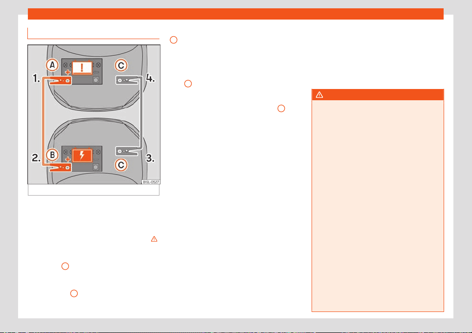
Self-help
Jump start: description
Fig. 41
Connection diagram.
Jump lead terminal connections
The jump l
eads shoul
d only be connect
ed
following the order
›››
Fig. 41 1. > 2. > 3. > 4.
●
Switch off the ignition of both vehicles
›››
.
●
Connect one end of the r
ed
jump l
ead to
the positive + terminal of the vehicle with the
flat battery
A
›
›
›
Fig. 41.
●
Connect the other end of the red jump lead
to the positive terminal + in the vehicle provid-
ing assistance
B
.
●
Connect one end of the bl
ack
jump l
ead
C
, to a suitable earth terminal, to a piece of
solid met
al that is bolt
ed t
o the crankcase or
to the crankcase of the vehicle itself that sup-
plies the power.
●
Connect the other end of the black jump
lead
C
, in to the vehicle with the discharged
batt
ery, t
o a piece of solid met
al that is bol-
ted to the crankcase or to the crankcase itself
but as far a possible from the battery
A
. Do
not connect the bl
ack jump l
ead t
o the nega-
tive pole – of the 12-volt battery. If it is con-
nected, this may cause an erroneous evalua-
tion of the state of the battery inside the elec-
tronic system of the vehicle.
●
Position the leads in such a way that they
cannot come into contact with any moving
parts in the engine compartment.
Make sure the battery clamps have sufficient
metal-to-metal contact with the battery ter-
minals.
Starting
●
Start the engine of the vehicle with the
boosting battery and let it run at idling speed.
●
Connect the vehicle's drive system with the
discharged 12-volt battery.
Removing the jump leads
●
Before you remove the jump leads, switch
off the dipped beam headlights if they are
switched on.
●
When the engine is running, disconnect the
leads in reverse order to the details given
above.
If the engine fails to start after about 10 sec-
onds, switch off the starter and try again after
about 1 minute.
WARNING
●
Please note the saf
ety warnings referring
to working in the engine compartment
›››
page 176.
●
The battery providing assistance must
have the same voltage as the flat battery
(12V) and approximately the same capaci-
ty (see imprint on battery). Failure to com-
ply could result in an explosion.
●
If one of the batteries is frozen, do not at-
tempt to start the engine with the jump
leads, as this may cause an explosion. Even
after the battery has thawed, battery acid
could leak and cause chemical burns. If a
battery freezes, it should be replaced.
●
Keep sparks, flames and lighted ciga-
rettes away from batteries, danger of ex-
plosion. Failure to comply could result in an
explosion.
●
Observe the instructions provided by the
manufacturer of the jump leads.
●
Do not connect the negative cable from
the other vehicle directly to the negative
terminal of the flat battery. The gas emit-
ted from the battery could be ignited by
sparks. Danger of explosion.
»
45
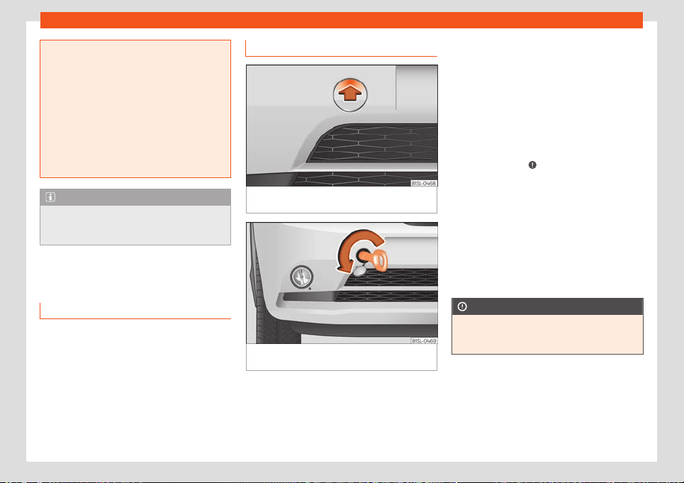
Emergencies
●
Never att
ach the negative cable to fuel
system components or the brake lines in
the other vehicle.
●
The non-insulated parts of the battery
clamps must not be allowed to touch. The
cable that goes to the positive pole of the
battery should never come into contact
with electrically conductive parts of the
vehicle, as this may cause a short circuit.
●
Do not lean on the batteries. This could
result in chemical burns.
Note
The vehicles must not touch each other,
otherwise electricity coul
d flow as soon as
the positive terminals are connected.
Tow start and towing
T
o
w st
art
The vehicle is not suitable for starting other
v
ehicl
es by t
owing.
Due to technical reasons it is not possible to
start the vehicle by towing. Try connecting
the drive system with the jump start
›››
page 44.
Front towline anchorage
Fig. 42
Right side of the front bumper: remove
the co
v
er
.
Fig. 43 Right side of the front bumper: towline
anchor
age in position.
The housing of the screw towing eye is on the
right side of the fr
ont bumper behind a lid
›
›
›
Fig. 42.
The towing eye should always be kept in the
vehicle.
Fitting the towline anchorage
●
Remove the towing eye from the vehicle
tool kit in the luggage compartment
›››
page 34.
●
Remove the cover by pressing down on the
top and leave it hanging from the vehicle
›››
Fig. 42.
●
Screw the towing eye in the housing by
turning it as far as it will go anticlock-
wise
›››
Fig. 43
›››
. Use a suitable object
that can compl
et
ely and secur
ely tighten the
towing eye in its housing.
●
After towing, unscrew the towing eye
clockwise with a suitable object.
●
Replace the cover and press on its lower
part until the tab snaps into the bumper.
●
Clean the towing eye if necessary and then
store it in the luggage compartment along
with the other vehicle tools.
CAUTION
The towing eye must always be completely
and firmly tightened. Otherwise, it coul
d be
released while towing and tow-starting.
46
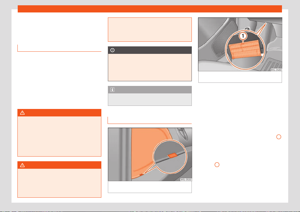
Fuses and bulbs
Fuses and bulbs
Fuses
Intr
oduction
In general, a fuse can be assigned to various
electrical components. Like
wise, an electrical
component can be protected by several
fuses.
Only replace fuses when the cause of the
problem has been solved. If a newly inserted
fuse blows after a short time, you must have
the electrical system checked by a special-
ised workshop as soon as possible.
WARNING
The high voltages in the electrical system
can give serious electrical shocks, causing
burns and e
ven death!
●
Never touch the electrical wiring of the
ignition system.
●
Take care not to cause short circuits in
the electrical system.
WARNING
Using unsuitable fuses, repairing fuses or
bridging a current circuit without fuses can
cause a fir
e and serious injury.
●
Never use a fuse with a higher value. Only
replace fuses with a fuse of the same am-
perage (same colour and markings) and
size.
●
Ne
ver replace a fuse by a metal strip, sta-
ple or similar.
CAUTION
To prevent damage to the vehicle's electric
syst
em, befor
e replacing a fuse always turn
off the ignition, the lights and all electrical
elements and remove the key from the igni-
tion.
Note
In the vehicle, there are more fuses than
those indicated in this chapter
.
Fuses inside the vehicle
Fig. 44
On the driver side: the instrument pan-
el fuse bo
x co
v
er.
Fig. 45 On the driver's side underneath the in-
strument panel: fuse box co
ver.
To open the instrument panel fuse box
●
Open the driver's door (front left).
●
Fit a flat object, i.e. a screwdriver, in the
gr
oo
v
e
›››
Fig. 44 and carefully lever to re-
move the cover.
Opening and closing the fuse box located
below the instrument panel
●
Open: Press the unlock button
›››
Fig. 45
1
until it is possible to open the cover. Fold the
co
v
er do
wn.
●
Close: Fold the cover up in the opposite di-
rection to the arrow until it clicks into the lock-
ing lever
1
.
»
47
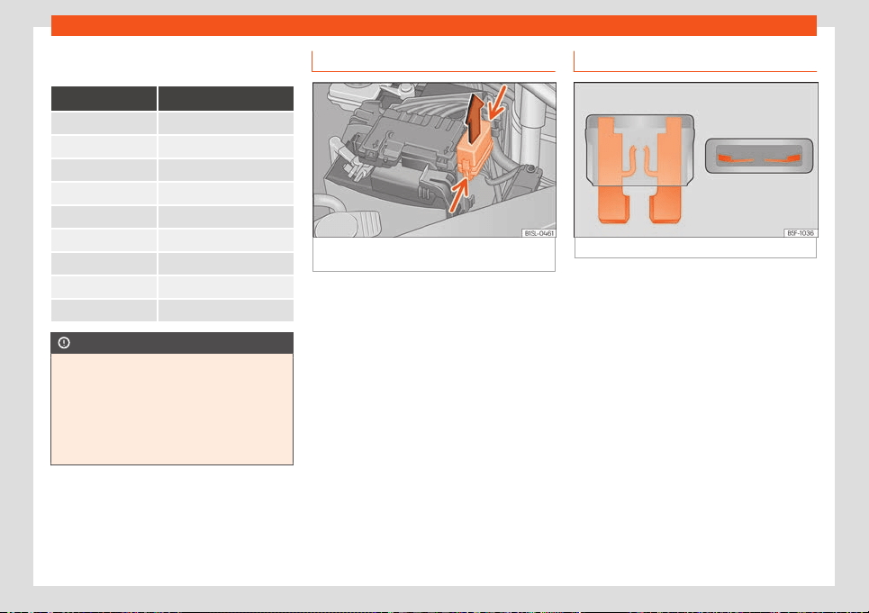
Emergencies
Identifying fuses below below the dash-
boar
d by col
ours
Colour Amp rating
Purple 3
Light brown 5
Brown 7.5
Red 10
Blue 15
Yellow 20
White or transparent 25
Green 30
Orange 40
CAUTION
●
Always car
efully remove the fuse box
covers and refit them correctly to avoid
problems with your vehicle.
●
Protect the fuse boxes when open to
avoid the entry of dust or humidity. Dirt and
humidity inside fuse boxes can cause dam-
age to the electrical system.
Fuses in the engine compartment
Fig. 46
In the engine compartment: fuse box
co
v
er
.
To open the engine compartment fuse box
●
Open the bonnet
›
›
›
page 176.
●
Press the locking tabs to release the fuse
box cover
›››
Fig. 46.
●
Then lift the cover out.
●
To fit the cover, place it on the fuse box.
Push the locking tabs down until they click
audibly into place.
Replace a blown fuse
Fig. 47
Image of a blown fuse.
Preparations
●
Switch off the ignition, lights and all electri-
cal equipment.
●
Open the corresponding fuse box
›
›
›
page 47,
›››
page 48.
Recognise a blown fuse
A fuse is blown if its metal strip is ruptured
›››
Fig. 47.
●
Point a lamp at the fuse to see if it has
blown.
To replace a fuse
●
Remove the fuse.
●
Replace the blown fuse by one with an
identical amperage rating (same colour and
markings) and identical size.
48
Fuses and bulbs
●
R
epl
ace the co
ver again or close the fuse
box lid.
Changing bulbs
Introduction
Changing bulbs requires a certain degree of
practical skill. If you are unsur
e, SEAT recom-
mends that you consult a technical service or
request assistance from a specialist. In gen-
eral a specialist is needed if, in addition to the
bulbs, other vehicle components require re-
moval.
If you choose to change the engine compart-
ment lamps yourself, remember that it is a
dangerous area
›››
.
Al
w
ays use identical bulbs with the same
designation. The name can be f
ound on the
base of the bulb holder.
Additional bulb specifications
The specifications of some headlamp bulbs
and bulbs for the rear lamps fitted at the fac-
tory may be different to those of conventional
bulbs. Bulb information is displayed on the
bulb socket or on the bulb itself.
Bulbs (12 V)
Light source used for each function
Halogen headlights. Type
Daytime running light/side
light
W21/5W
Dipped beam headlights H4 LL
Main beam headlights H4 LL
Turn signal PY21W NA
Rear bulb light Type
Brake/side lights P21/5W LL
Side lights P21/5W LL
Turn signal PY21W NA LL
Retro fog light P21W
Reverse lights R10W
WARNING
●
Take par
ticular care when working on
components in the engine compartment if
the engine is warm. Risk of burns.
●
The H4, HB4 and H7 bulbs are pressur-
ised. They may explode when being re-
placed, and there is a danger of injury.
●
Only replace the bulbs concerned when
they have cooled.
●
When changing bulbs, please tak
e care
not to injure yourself on sharp edges, in
particular on the headlight housing.
●
Never replace bulbs alone if you are not
familiar with the operations necessary. If
you are not sure about procedures then vis-
it a specialised workshop to carry out the
necessary work.
●
Never touch the bulb glass directly. Fin-
gerprints will be evaporated by the heat of
the operating bulb thus “fogging” up the
reflector.
CAUTION
●
If, after r
eplacing a bulb, the rubber cover
is not correctly positioned in the headlight
housing, water or humidity can enter and
damage the electrical system.
●
Remove the ignition key before working
on the electric system. Otherwise, a short
circuit could occur.
●
Switch off the lights and the parking light
before changing a bulb.
●
Take good care to avoid damaging any
components.
For the sake of the environment
Please ask your specialist retailer how to
dispose of used bulbs in the proper manner.
»
49
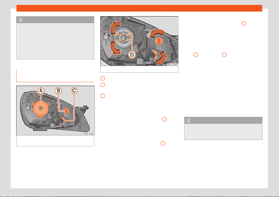
Emergencies
Note
●
Please check at regul
ar intervals that all
lighting (especially the exterior lighting) on
your vehicle is functioning properly. This is
not only in the interest of your own safety,
but also that of all other road users.
●
Before changing a bulb, make sure you
have the correct new bulb.
Changing the bulbs in the head-
lights
Fig. 48
In the engine compartment: rear view
of the l
eft headlight with rubber co
v
er.
Fig. 49 Left headlight
Dipped and main beam headlights
Dipped beam lights and daytime running
lights
T
urn signal
Ther
e is no need t
o remove the headlight to
replace bulbs.
Dipped and main beam headlight
A
●
Open the bonnet .
●
Remove the H4 lamp connector and the
rubber co
v
er fr
om the tabs.
●
Press the retaining clip
›››
Fig. 49
D
down-
w
ar
ds in the dir
ection of the arrow, unclip
sideways, and remove it.
●
Remove the bulb from the holder. If neces-
sary, press the lock on the bulb holder.
●
Replace the faulty bulb with a new identical
bulb.
A
B
C
●
Insert the bulb
, r
et
urn it to its position and
insert the retaining clip
›››
Fig. 49
D
.
●
Place the rubber cover and check that is in
the corr
ect position. Insert the connect
or t
o
the bulb H4.
Dipped beam light and daytime running
light
B
/ Turn signal
C
●
Open the bonnet
●
Turn the bulb holder in an anticl
ockwise
dir
ection
as far as it will go and remove it,
along with the bulb, pulling backwards.
●
Remove the bulb from the holder. If neces-
sary, press the lock on the bulb holder.
●
Replace the faulty bulb with a new identical
bulb.
●
Insert the bulb holder in the headlight and
turn it clockwise as far as the stop.
Note
The images show the left hand headlight
from behind. The structur
e of the right hand
side headlight is symmetric.
50
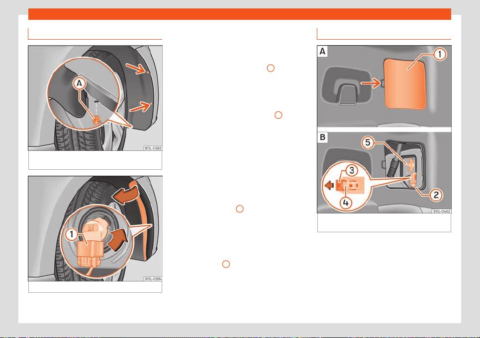
Fuses and bulbs
Replacing the front bumper bulb
Fig. 50
Right front wheel arch: access to the
bulb
Fig. 51 Changing the bulbs in the headlights
●
Unscr
e
w the 2 r
etaining screws of the wheel
arch trim
›››
Fig. 50 (arrows) with the screw-
driver from the vehicle took kit
›››
page 34.
●
Unscrew the expansive rivet in the lower
front part of the wheel arch trim
A
with the
scr
e
w
driver from the vehicle tool kit and com-
pletely remove it
›››
page 34.
●
Carefully fold the wheel arch trim to the
side.
●
Release the connector
›››
Fig. 51
1
and re-
mo
v
e it.
●
T
urn the bulb holder
›››
Fig. 51 in the direc-
tion of the arrow, in an anticlockwise direc-
tion as far as it will go and remove it, along
with the bulb, pulling backwards.
●
Replace the faulty bulb with a new identical
bulb.
●
Insert the bulb holder in the headlight and
turn it clockwise as far as the stop.
●
Plug the connector
1
into the bulb holder.
The connect
or must audibly click int
o pl
ace.
●
Replace the wheel arch trim into its posi-
tion.
●
Place the expansive rivet in the wheel arch
trim and bumper and press it completely in-
wards
›››
Fig. 50
A
.
●
Securely screw the 2 retaining screws
›
›
›
Fig. 50 (arrows) with a screwdriver.
Changing the bulbs in the tail lights
Fig. 52
On the side of the luggage compart-
ment: r
emo
v
e the tail light unit.
»
51
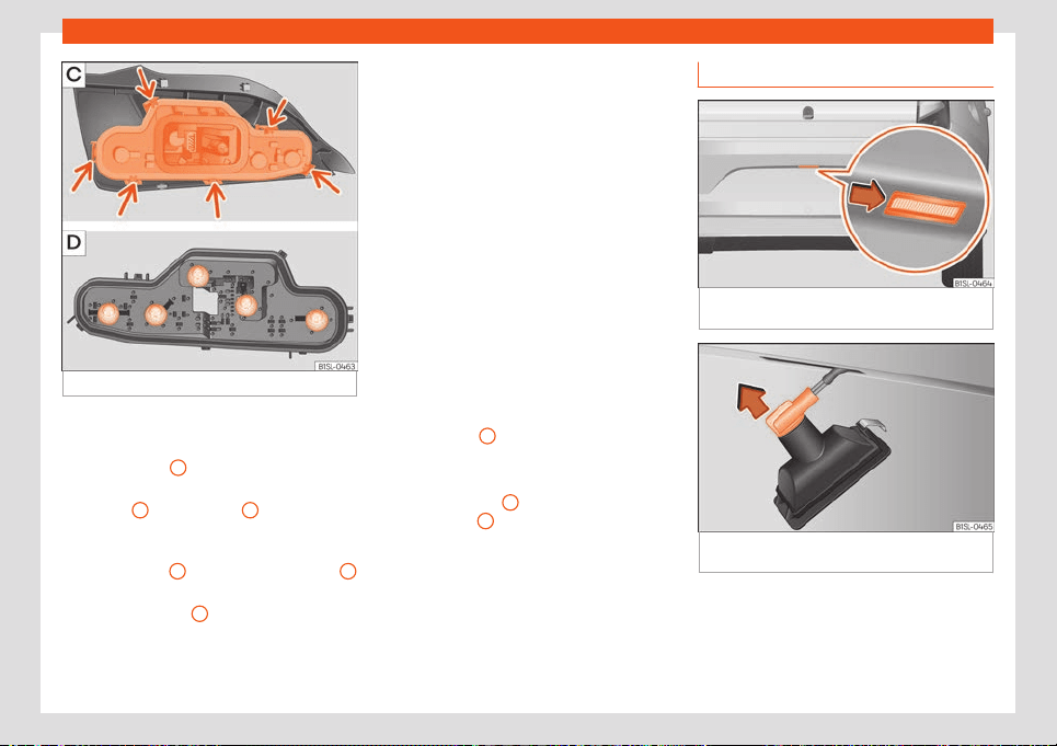
Emergencies
Fig. 53
Tail light unit: remove the bulb holder
Removing the rear light units
●
Open the rear lid.
●
Remove cover
1
by carefully levering it
›
›
›
Fig. 52 .
●
Pull lock
3
on connector
2
in the direction
of the arr
o
w
›
››
Fig. 52 . Help yourself with
the screwdriver from the vehicle tool kit.
●
Press fastener
4
and remove connector
2
›››
Fig. 52 .
●
Unscrew wing nut
5
›
›
›
Fig. 52 .
●
Remove the tail light from the bodywork by
carefully pulling backwards.
●
Disassemble the tail light unit and place it
on a flat, clean surface.
To change the bulb
●
Unlock the bulb holder on the locking flang-
es (arrow)
›››
Fig. 53 and remove the bulb
holder from the tail light.
●
Replace the damaged bulb with a new
identical bulb
›››
Fig. 53 .
●
Place the bulb holder in the tail light unit.
The locking tabs (arrow) must be heard to en-
gage
›››
Fig. 53 .
Assembling the rear light units
●
Carefully insert the tail light unit into the
opening in the bodywork.
●
Hold the tail light in the installation position
with one hand and tighten the wing nut with
the other hand
5
›
›
›
Fig. 52 .
●
Ensure that the tail light unit has been cor-
rectly fitted and is firmly secured.
●
Insert connector
2
into the bulb holder
and pr
ess l
ock
3
on the connector in the di-
r
ection opposit
e t
o the arrow
›››
Fig. 52 .
●
Insert the cover. The cover should lock into
place.
●
Close the rear lid.
Changing the number plate bulb
Fig. 54
In the rear bumper: detach the number
pl
at
e light.
Fig. 55
Number plate light: remove the bulb
hol
der
.
●
With one hand, press on the number plate
light fr
om l
eft t
o right and remove it from the
bumper
›››
Fig. 54.
●
Detach the number plate light carefully
from the bumper.
52
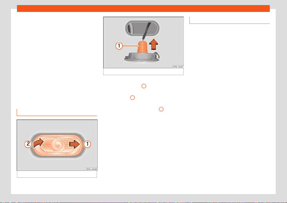
Fuses and bulbs
●
T
urn the bulb hol
der with the bulb
anti-
clockwise and remove it in the direction of
the arrow
›››
Fig. 55.
●
Replace the faulty bulb with a new identical
bulb.
●
Place the bulb holder in the number plate
light and press in the opposite direction to the
arrow as far as possible
›››
Fig. 55.
●
Insert the number plate light carefully into
the left edge of the opening on the bumper.
During this process, check that the assembly
direction of the number plate light is correct,
i.e. the spring must be on the right.
●
Insert the number plate light into the bump-
er until it audibly clicks into place.
Replace the side turn signal bulb
Fig. 56 Removing the side turn signal
Fig. 57 Side turn signal: Bulb replacement.
●
With one hand move the side turn signal
backw
ar
ds
›
››
Fig. 56
1
.
●
Remove the side turn signal from the chas-
sis by l
e
v
erage
2
.
●
Remove the bulb holder with the bulb in the
dir
ection of the arr
o
w
›››
Fig. 57
1
.
●
Remove the bulb holder bulb in a straight
dir
ection.
●
R
epl
ace the faulty bulb with a new identical
bulb.
●
Install the bulb holder.
●
Place the side turn signal on the chassis on
the side situated towards the rear of the vehi-
cle until the spring clicks into the other side of
the side turn signal.
Additional brake light
Taking into account that it consists of LED
bulbs, the change should be made at a tech-
nical service centr
e.
53
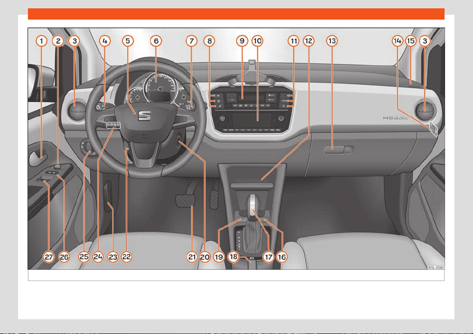
Operation
Fig. 58
Instruments and controls.
54

Controls and displays
Operation
Contr
ol
s and displ
ays
Interior view
Overview
Door handle . . . . . . . . . . . . . . . . . . . . . . . . . . 72
Switch for adjusting the exterior mir-
rors . . . . . . . . . . . . . . . . . . . . . . . . . . . . . . . . . . . 85
Air v
ents . . . . . . . . . . . . . . . . . . . . . . . . . . . . . . 102
Lever for
–
Turn signals and main beam
headlights
. . . . . . . . . . . . . . . . . . . . . . . . . . 78
–
Cruise control system (CCS) . . . . . 146
Steering wheel with horn and driver
airbag . . . . . . . . . . . . . . . . . . . . . . . . . . . . . . . . 22
Instrument panel . . . . . . . . . . . . . . . . . . . . . 56
Lever for:
–
Wipers and rear window wiper . . . . 82
–
Multi-function display control . . . . . 63
Buttons for:
–
Windscreen heating . . . . . . . . . . . . . . . 101
–
Rear window heater . . . . . . . . . . . . . . . 101
–
Left seat heating controls . . . . . . . . . 103
Controls for the Climatronic . . . . . . . . . 100
1
2
3
4
5
6
7
8
9
Radio (factory fitted) . . . . . . . . . . .
. . . . . . 107
Butt
ons f
or:
–
Turn the emergency lights on and
off . . . . . . . . . . . . . . . . . . . . . . . . . . . . . . . . . . 80
–
Lane Assist . . . . . . . . . . . . . . . . . . . . . . . . . 148
–
Right seat heating controls . . . . . . . 103
Storage compartment with drink
holder in the centre console . . . . . . . . . 95
Storage glove compartment . . . . . . . . 94
–
Tyre pressure monitoring . . . . . . . . . . 192
Key switch for switching off the front
passenger airbag . . . . . . . . . . . . . . . . . . . . 23
front passenger front airbag . . . . . . . . 22
12 volt socket or cigarette light-
er* . . . . . . . . . . . . . . . . . . . . . . . . . . . . . . . . . . . . 97
automatic gearbox lever . . . . . . . . . . . . 140
Handbrake . . . . . . . . . . . . . . . . . . . . . . . . . . . 152
Controls for:
–
Selecting the driving profile . . . . . . . 144
–
Selecting charging mode . . . . . . . . . 160
Ignition lock . . . . . . . . . . . . . . . . . . . . . . . . . . 135
Pedals
Steering column adjustment lev-
er . . . . . . . . . . . . . . . . . . . . . . . . . . . . . . . . . . . . . 13
Open bonnet lever . . . . . . . . . . . . . . . . . . . 177
Headlight range control . . . . . . . . . . . . . 80
Light switch . . . . . . . . . . . . . . . . . . . . . . . . . . 76
Central locking button . . . . . . . . . . . . . . . 69
10
11
12
13
14
15
16
17
18
19
20
21
22
23
24
25
26
Buttons for operating the front elec-
tric windo
ws
. . . . . . . . . . . . . . . . . . . .
. . . . . . 75
27
55

Operation
Instruments and warn-
ing/contr
ol l
amps
Instrument panel
Intr
oduction
WARNING
Any distraction may lead to an accident,
with the risk of injury.
●
Do not operate the instrument panel con-
trols when driving.
●
T
o reduce the risk of accident and injury,
only make adjustments to the instructions
on the instrument panel display and to the
instructions on the Infotainment system
display when the vehicle is stationary.
56
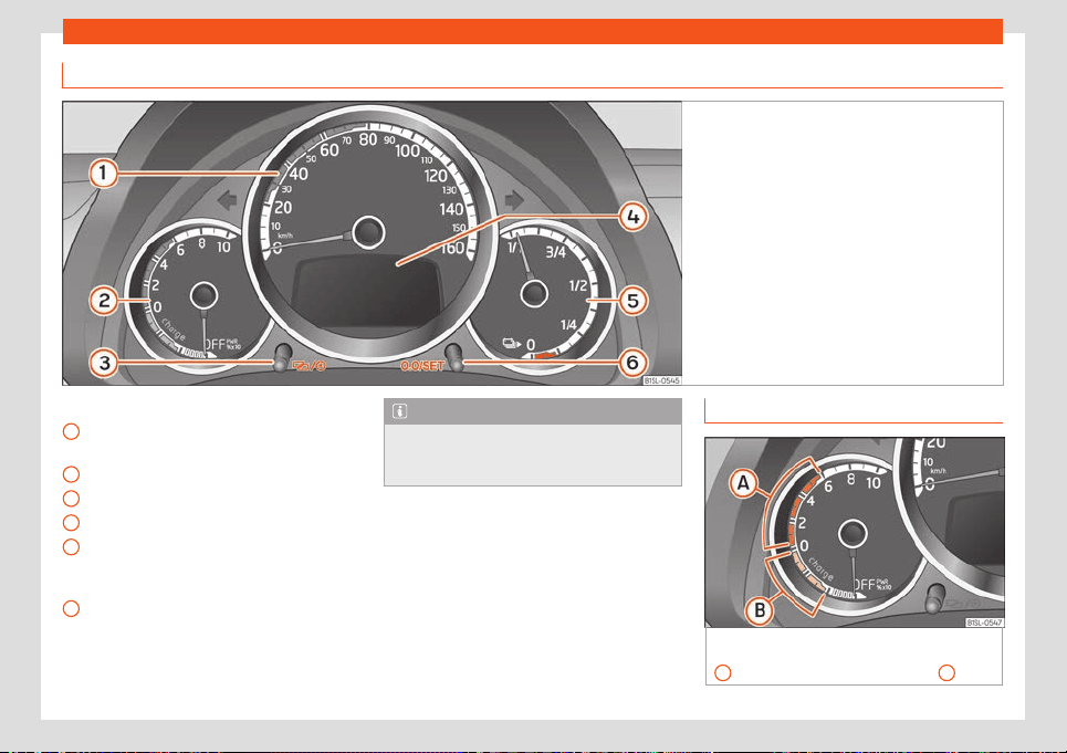
Instruments and warning/control lamps
Analogue instrument panel
Fig. 59
Front passenger airbag located in instru-
ment panel.
Details of the instruments
›
›
›
Fig. 59:
Speedometer. Depending on the vehicle
in km/h or in mph.
Power display
›››
page 57
Time set button
›››
page 59
Display indications
›››
page 59.
Charge level display: indicates the level
of charge of the high voltage battery
›››
page 163.
Reset button for trip recorder (trip).
1
2
3
4
5
6
Note
Depending on the vehicle, other functions
of the multifunction display can be dis-
played on the scr
een of a mobile phone.
Power display and available power
Fig. 60
On the instrument panel: power dis-
pl
ay with z
ones f
or low consumption operation
A
and for brake energy recuperation
B
.
»
57
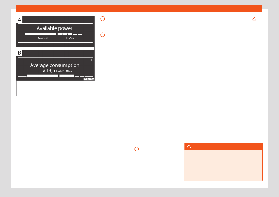
Operation
Fig. 61
On the instrument panel display: avail-
abl
e po
w
er.
: Indication displayed complete-
ly.
: Indication moved down.
When the drive system is connected and
whil
e driving, inf
ormation on the po
wer used
and on the available power is displayed in the
instrument panel display.
Power display
When connecting the drive system before
starting to move, the indicator changes from
to
›››
Fig. 60.
When the vehicle is moving, the power used
at that moment to move is indicated in the in-
strument panel display (in % PWR x 10)
›››
Fig. 60.
When the indicator needle is in the blue
zone, the vehicle is moving with a particu-
larly low energy consumption.
When the indicator needle is in the green
zone, the brake energy and kinetic energy
are converted into electrical energy (en-
ergy recuperation) by the electric drive
system and stored in the high-voltage
battery.
Indication of available power
While driving, the current available power of
the electric engine is displayed on the instru-
ment panel display
›››
Fig. 61 . When the in-
strument panel display changes to another
indication, the indication of the available
power moves downwards
›››
Fig. 61 .
When all segments are displayed, it means
that the maximum power of the electric en-
gine is available. Having high power available
is necessary for, i.e. accelerating the vehicle
quickly to, for example, overtake safely.
If a lot of power is required for a long period
of time (it is mainly seen because the power
indicator needle is above the low consump-
tion zone
›››
Fig. 60
A
), the time during
which the maximum po
w
er is av
ailable is re-
duced. In the indication of the available pow-
er, the segments of the E-Max zone turn off
from right to left.
When all segments of the E-Max zone turn off,
it means that the maximum power of the
A
B
electric engine is no longer available
›
›
›
. If
ther
e is still a high demand, the po
w
er cur-
rently available is reduced, which is indicated
by the shortening of the Normal zone bar,
starting from the right. Based on the length of
the bar, it is possible to know how much the
drive power has been reduced. If less power
is then used, the available power gradually
increases once again.
Limited availability of power may be related
to driving behaviour, i.e., accelerating the ve-
hicle quickly. In general, the available power
is limited under the following conditions:
●
The temperature of the high-voltage bat-
tery is very low or very high.
●
The level of charge of the high-voltage bat-
tery is low.
When the charge level of the high-voltage
battery approaches the reserve level, in addi-
tion to the available power, the maximum
speed at which the vehicle can be driven is
also reduced. Charge the high voltage bat-
tery as soon as possible
›››
page 160.
WARNING
If the vehicle is driven with a very low a
charge le
vel of the high-voltage battery,
the vehicle may stall in traffic, causing seri-
ous damage or accidents and injuries.
●
Always ensure that the charge level of
the high-voltage battery is sufficient!
58
Instruments and warning/control lamps
WARNING
When the maximum power reserve is not
availabl
e or the level of charge of the high
voltage battery is low, the driving proper-
ties may vary, i.e. the acceleration behav-
iour of the vehicle.
●
Always adapt the speed and driving style
to the conditions of visibility, weather, road
and traffic, as well as the charge level of
the high-voltage battery.
CAUTION
Leaving the vehicle parked for a long peri-
od of time with the high-voltage batt
ery
discharged may cause irreversible damage
to the battery.
●
Always charge the high-voltage battery
immediately.
Status display
A variety of information can be viewed on the
instrument panel displ
ay
›
›
›
Fig. 59
2
, de-
pending on the v
ehicl
e equipment:
●
Doors, bonnet and r
ear lid open
●
Warning and information messages.
●
Current driving profile
●
Odometer.
●
Indication of available power
›››
page 57
●
Time.
●
Outside temperature.
●
Selector lever positions
›››
page 140.
●
Multifunction display (MFI)
›››
page 63
●
Service interval display
›››
page 63.
●
Range indication
●
Seat belt status display for rear seats
›››
page 14.
●
Remaining charge time when charging the
high-voltage battery
›››
page 169
Doors, bonnet and rear lid open
When the vehicle is unlocked and while driv-
ing, the instrument panel display shows if any
of the doors, the bonnet or rear lid are
opened and, in some cases, it is also indica-
ted by an audible warning. The display may
vary according to the type of instrument pan-
el fitted.
Warning and information messages
The system runs a check on certain compo-
nents and functions when the ignition is
switched on and while the vehicle is moving.
The anomalies are displayed on the instru-
ment panel display by means of warning
symbols which, depending on the case, may
also be accompanied by an acoustic warn-
ing. The display may vary according to the
type of instrument panel fitted.
Current driving profile
You can choose between three different driv-
ing profiles. After changing the driving profile,
the new selected profile is displayed on the
instrument panel display for a few seconds.
Odometer
The odometer registers the total distance
travelled by the car.
The odometer (trip) shows the distance
travelled since the last odometer reset. The
last figure indicates 100 m.
●
Briefly press the button to change
from the trip odometer and the range indica-
tion.
●
While viewing the trip odometer, press the
button for longer to reset the trip od-
ometer and, if necessary, other indications of
the multifunction display
›››
page 61. If you
press the button for more than 5 seconds, the
“old” value of the trip odometer is reset.
Indication of available power
While driving, the current available power of
the electric engine is displayed on the instru-
ment panel display
›››
page 57.
Time
●
Switch the ignition on.
●
To adjust the time, if necessary, change to
the indication of the same; to do this, press
»
59
Operation
the rocker switch on the wiper lever or the ad-
justment butt
on on the instrument panel.
●
Pr
essed the butt
on and hold pressed
to mark the hour field. This will flash.
●
To move forward, press the button . To
move quickly, keep it pressed.
●
Briefly press the button to change to
the minute field. This will flash.
●
To move forward, press the button . To
move quickly, keep it pressed.
●
To finish setting the time, press the button
again .
Outside temperature indicator
When the outside temperature is below +4°C
(+39°F), the “ice crystal” (risk of frost warn-
ing) symbol is displayed in addition to said
temperature. At first this symbol flashes and
then it remains lit until the outside tempera-
ture rises above +6°C (+43°F)
›››
.
When the v
ehicl
e is st
opped, when the inde-
pendent air conditioning is connected or
when driving at very low speed, the indicated
outside temperature may be higher than the
real one due to the heat emitted by the elec-
tric drive system.
The temperatures measured range from
-40°C to +50°C (-40°F to +122°F).
Selector lever positions
The current position of the selector lever is
displayed both next to the lever, using illumi-
nated letters, and on the instrument panel
display.
Range indication
It indicates the approximate distance in km
that can still be travelled with the current ca-
pacity of the battery charge if the same driv-
ing style is maintained. The calculation is
made based on current energy consumption,
among other factors.
●
To change between the indication of the
range and the trip odometer, briefly press the
adjustment button located on the instrument
panel.
Seat belt status display for rear seats*
The seat belt status display on the instrument
panel display informs the driver, when the ig-
nition is switched on, whether any passen-
gers in the rear seats have fastened their seat
belts
›››
page 14.
WARNING
If the warning lamps are ignored, the vehi-
cle may stall in tr
affic, or may cause acci-
dents and severe injuries.
●
Never ignore the warning lamps.
●
Stop the vehicl
e safely as soon as possi-
ble.
●
A faulty vehicle represents a risk of acci-
dent for the driver and for other road users.
If necessary, switch on the hazard warning
lamps and put out the warning triangle to
advise other drivers.
●
Park the vehicle away from traffic and
ensure that no highly flammable materials
are under the vehicle that could come into
contact with the exhaust system (e.g. dry
grass, fuel).
WARNING
Even though outside temperatures are
above fr
eezing, some roads and bridges
may be icy.
●
At outside temperatures above +4°C
(+39°F), even when the “ice crystal sym-
bol ” is not visible, there may still be patch-
es of ice on the road.
●
The outside temperature sensor takes a
guideline measurement.
CAUTION
Failure to heed the warning lamps when
they appear may result in faults in the v
ehi-
cle.
Note
When several warnings are active at the
same time, the symbols ar
e shown
60
Instruments and warning/control lamps
successively for a few seconds and will
stay on until the fault is r
ectified.
Driving data indicator (multifunc-
tion display)
The display of the travel data (multifunction
display) shows diff
erent values about the
journey and the consumption.
Change from one display to another
●
Press rocker switch
›
›
›
Fig. 62
2
on the
windscr
een wiper l
e
ver.
Driving data memories
The multifunction display has two automatic
memories:
Partial memory: The memory collects
journey and consumption data from
when the ignition is turned on until when
it is turned off. The memory is automati-
cally deleted if the journey is interrupted
for more than 2 hours. If the journey is
continued in less than 2 hours after the
ignition is switched off, the new data is
added to the data already stored in the
memory.
Total memory: The memory records the
values for a specific number of partial
trips, up to a total of 19 hours and 59 mi-
1
2
nutes, or 1,999.9 km (miles), depending
on the model of instrument panel. On
reaching either of these limits, the mem-
ory is automatically erased and starts to
count from 0 again.
The selected memory will be shown in the
upper right-hand corner of the display.
Changing memory
●
With the ignition switched on, and display-
ing memory 1 or 2, briefly press button
›
›
›
Fig. 62
1
to change from one
memory t
o another
Manually er
asing memory 1 or 2
●
Sel
ect the memory that you wish to erase.
●
Hold button
pressed for about 2
seconds.
P
ossibl
e displ
ays
●
Time: Current time in hours (h) and minutes
(min).
●
Travelling time: This indicates the hours (h)
and minutes (min) since the ignition was
switched on.
●
Consumption: The current energy con-
sumption is indicated. While driving, it is indi-
cated in kilowatt-hours per 100 kilometres
(kWh/100 km). When the vehicle is stopped
with the drive system on, current energy con-
sumption is indicated in kWh.
●
Average consumption: Indication of the
average power consumption in kilowatt-hour
per 100 kilometres (kWh/100 km). The indica-
tion appears after travelling approximately
100 meters. Until then, dashes appear. The
indicated value is updated every 5 seconds
approx.
●
Range: It indicates the approximate dis-
tance in km that can still be travelled with the
current capacity of the battery charge if the
same driving style and consumption are
maintained. The calculation is made based
on current energy consumption, among other
factors. Keep in mind that autonomy can vary
very considerably if, for example, the climate
control is switched on or off or if the driving
profile is changed. In the calculation of the
autonomy, the difference between the tem-
perature of the passenger compartment and
the outside temperature when the climate
control is connected also influences. The fol-
lowing applies to the forecast autonomy: The
more energy the convenience consumers
use, such as climate control and seat heating,
the less energy will be available for the rest of
the journey.
●
Power availability: While driving, the cur-
rent available power of the electric engine is
displayed on the instrument panel display
›››
page 57.
●
Distance: Distance in km travelled since
the ignition was switched on.
»
61
Operation
●
Av
er
age speed:
After switching on the igni-
tion, the average speed starts to be dis-
played after tavelling approximately 100 me-
ters. Otherwise horizontal lines are displayed.
The value shown is updated approximately
every 5 seconds.
●
Digital speed display: Current speed dis-
played digitally.
●
Digital outside temperature display: Cur-
rent outside temperature in digital format.
●
Speed warning at --- km/h: If the stored
speed is exceeded, between 30 km/h (18
mph) and 250 km/h (155 mph), an acoustic
warning is sounded and, if necessary, an op-
tical warning also. Depending on the country,
this warning also occurs when driving at
speeds above 120 km/h (75 mph). This warn-
ing is mandatory by law and you are not al-
lowed to change it.
Storing a speed for the speed warning
●
Select the display Speed warning at
--- km/h.
●
Press the button
on the wiper lever
t
o memorise the curr
ent speed and deacti-
v
ate the warning.
●
Adjust to the desired speed for 5 seconds
using the rocker switch
on the wiper lever.
Ne
xt, pr
ess the
again or wait for a few
seconds. The speed is st
or
ed and the w
arn-
ing activated.
●
To deactivate, press
. The stored
speed is del
et
ed.
W
arning and information messages
(Vehicle status)
The system runs a check on certain compo-
nents and functions when the ignition is
switched on and whil
e the vehicle is moving.
Faults displayed on the instrument panel as
red and yellow warning symbols accompa-
nied with messages and, depending on the
case, even an audible warning
›››
page 65.
The representation of the messages and
symbols may vary depending on the version
of the instrument panel.
Priority 1 warning (red)
The symbol lights up or flashes (in part ac-
companied by audible warnings). Stop
driving! Danger! Check the fault and elimi-
nate the cause. If necessary, seek professio-
nal assistance.
Priority 2 warning (yellow)
The symbol lights up or flashes (in part ac-
companied by audible warnings). Operating
faults or the lack of operating fluids can
cause damage to the vehicle or a fault.
Check the faulty function as soon as possible.
If necessary, seek professional assistance.
Information message
It provides inf
ormation about processes in the
vehicle.
Settings Menu
The actual number of menus available and
the names of their options depend on the
electronic syst
em and the vehicle’s equip-
ment.
Multifunction display
Information and configuration options of the
multifunction indicator
›››
page 61.
Vehicle status
Current warning and information messages.
This menu option only appears when there
are messages of this type. The number of ex-
isting messages is indicated on the display.
Language
Setting the language of the texts on the dis-
play.
Multifunction display data
Setting the data that must be displayed on
the multifunction display of the instrument
panel display.
62
Instruments and warning/control lamps
Time
Hours and minut
es of the instrument panel
cl
ock
. The time can be displayed in 12 or 24
hour format. If necessary, an S appears at the
top of the display to indicate that the summer
time is set.
Units
Adjusting the temperature, consumption and
distance units.
Service
Checking service messages.
Factory settings
The default factory setting of some functions
are reset in the Settings menu.
Service intervals
The inspection message appears on the in-
strument panel displ
ay
›
›
›
Fig. 59
2
.
The dat
es of the services (i.e
. the ne
xt Inspec-
tion Service or change of brake fluid) are de-
tailed on the sticker on the door pillar or in the
Maintenance Schedule.
The set service intervals have been specified
with the service dependent on time/dis-
tance travelled.
Inspection reminder
If an inspection expires soon, an Inspection
reminder appears in the form of an abbrevia-
tion and an indication in km appears when
the ignition is switched on. The number of kil-
ometres shown is the maximum number that
may be driven until the next service.
Service due
After the service date, an audible warning is
given when the ignition is switched on and the
abbreviation will flash on the display for a
few seconds.
Check the service date
With the ignition switched on, the engine off
and the vehicle stopped, the current service
can be checked:
●
Select the menu Settings.
●
Select the Information option from the
Service submenu. If the service has not
been carried out when due, Service from
--- km or --- days will appear on the in-
strument panel display.
Restart the service interval display
If the service has not been performed by a
SEAT dealer, the indicator can be reset in the
instrument panel as described below:
●
Switch the ignition off.
●
Press the button on the instrument
panel and keep it pressed.
●
Switch ignition back on.
●
Release the button and press it again
briefly before about 10 seconds have
elapsed.
Do not restart the indicator between the
service intervals, otherwise the information
displayed will be incorrect.
Note
●
The service message disappears after a
fe
w seconds, when the engine is started or
when the
button is pressed on the
wiper lev
er.
●
If the 12-volt battery was disconnected
for a long period of time, it will not be possi-
ble to calculate the days remaining until
the next service. Hence, the indicator may
show incorrect calculations. In this case it
will be necessary to take into account the
maximum maintenance intervals allowed
›››
page 194.
Using the instrument panel
Intr
oduction
With the ignition switched on it is possible to
access diff
er
ent messages via the displ
ay on
the instrument panel display.
»
63
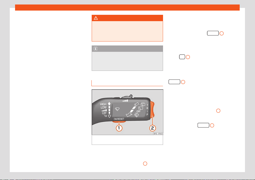
Operation
Some menu options can only be read when
the v
ehicl
e is st
ationary.
The number of messages displayed on the in-
strument panel display will vary according to
the vehicle electronics and equipment.
A specialised workshop will be able to pro-
gramme or modify additional functions, ac-
cording to the vehicle equipment. SEAT rec-
ommends taking your car in for technical
service.
Instrument panel menus
■
Multifunction display
›››
page 61
■
Audio.
■
Telephone.
■
Vehicle status
›››
page 62.
■
Setup
›››
page 62
Main menu
●
MFA: Information and setting options of the
multifunction indicator
›››
page 61
●
Vehicle status: Current warning and infor-
mation messages. This menu option only ap-
pears when there are messages of this type.
The number of existing messages is indicated
on the display. Example: 1/1 or 2/2
›››
page 59.
●
Settings: Different setting options, i.e. for
the time, language and units
›››
page 62.
WARNING
Distracting the driver in any way can lead
to an accident and cause injuries.
●
Nev
er use the menus on the instrument
panel display while the vehicle is in motion.
Note
After loading or changing the 12-volt bat-
tery, check the system settings. If the po
w-
er supply is interrupted, the system settings
might be incorrect or deleted.
Operation with the wiper lever
Fig. 62
Wiper lever: buttons for using the in-
strument panel menus.
As long as a priority 1
›
›
›
page 62 warning is
active, it will not be possible to access any
menu. Some warnings can be confirmed and
hidden with the button
›››
Fig. 62
1
.
Select a menu or an informative display
●
Switch the ignition on.
●
If a message or a vehicle pictogram is dis-
pl
ayed, pr
ess the butt
on
1
; several
times if necessary.
●
To display the menus or to return to the
menu sel
ection fr
om a menu or fr
om an infor-
mation displays, press and hold the rocker
switch
2
.
●
To change from one menu to another, press
the upper or l
o
w
er part of the rocker switch.
●
To open the menu or the information dis-
play that is displayed, press the button
1
or wait a few seconds until the
menu or inf
ormation displ
ay opens aut
omati-
cally.
Changing menu settings
●
In the menu displayed, press the upper or
lower part of the rocker switch
2
until the re-
quir
ed menu option is check
ed. The option
appears fr
amed.
●
Press the button
1
to make the de-
sir
ed modifications. A mark indicat
es that the
syst
em or function is activated.
Back to menu selection
Select Back on the corresponding menu to
exit.
64

Instruments and warning/control lamps
Note
If when switching on the ignition warnings
are shown about e
xisting faults, it might not
be possible to change the settings or show
the information as described. In this case,
go to a specialised workshop and request a
repair.
Control lamps
Control and warning l
amps
The control and warning lamps are indicators
of w
arnings
›
›
›
, faults or certain functions.
Some contr
ol and w
arning l
amps come on
when the ignition is switched on, and switch
off when the engine starts running, or while
driving.
When certain control and warning lamps are
lit, an audible warning is also heard.
Red warning lamps
Handbrake
›››
page 150.
Fault in the brake system
›
›
›
page 150.
Coolant of the drive system
›››
page 178.
Fault in the steering system
›››
page 144.
Driver or passenger has not fastened
seat belt
›››
page 14.
Fault in the generator
›››
page 185.
Failure in the electric drive system
›››
page 140.
Yellow warning lamps
Fault in ESC or disconnection caused
by the syst
em;
OR
ESC or ASR in oper-
ation
›››
page 152.
Fault in Traction Control* or discon-
nection caused by the system; OR
T
raction Control* in operation
›››
page 152.
Fault in the ABS
›››
page 152.
Rear fog light switched on
›››
page 76.
Fault in the engine management
›››
page 135.
The operation of the electromechani-
cal steering is limited
›
››
page 144.
High-voltage battery charging; OR
lev
el of charge of the high-voltage
battery is low.
Fault in airbag system and seat belt
tensioners
››
›
page 22.
Failure in the electric drive system
›››
page 140.
Almost empty high-voltage battery
›››
page 160.
Tyre pressure monitor system
›››
page 192.
Lane Assist warning system in opera-
tion
›››
page 148.
Green indicator lamps
Turn lights or emergency lights on
›››
page 76.
Cruise control
›››
page 146.
Press the foot brake
›
›
›
page 140.
Indication that the drive system is con-
nected
››
›
page 136.
Lane assist warning (Lane Assist)
›››
page 148.
Blue indicator lamps
Main beam on or flasher on
›››
page 76.
Other warning lamps
Door(s), rear lid or bonnet open or not
properly closed
›
››
page 59.
Charging connector plugged in
›››
page 164.
A passenger in the rear seats has fas-
tened their seat belt
››
›
page 14.
»
65
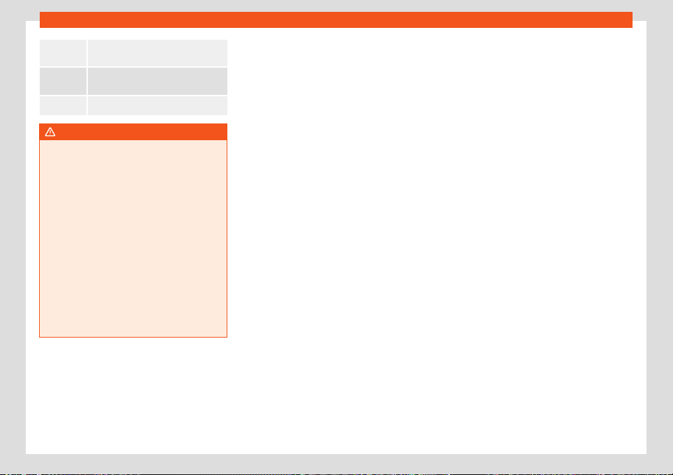
Operation
A passenger in the rear seats has not
fastened their seat belt
›
››
page 14.
The outside temperature is below
+4°C (+39°F)
›››
page 60.
Service interv
al display
›››
page 63.
WARNING
If the warning lamps and messages are ig-
nored, faults may occur in the v
ehicle, it
may stall in traffic, or accidents and seri-
ous injuries may occur.
●
Never ignore warning lamps or text mes-
sages.
●
Stop the vehicle safely as soon as possi-
ble.
●
A faulty vehicle represents a risk of acci-
dent for the driver and for other road users.
If necessary, switch on the hazard warning
lamps and put out the warning triangle to
advise other drivers.
●
In any vehicle, the engine compartment is
a hazardous area and could cause severe
injuries
›››
page 176.
66
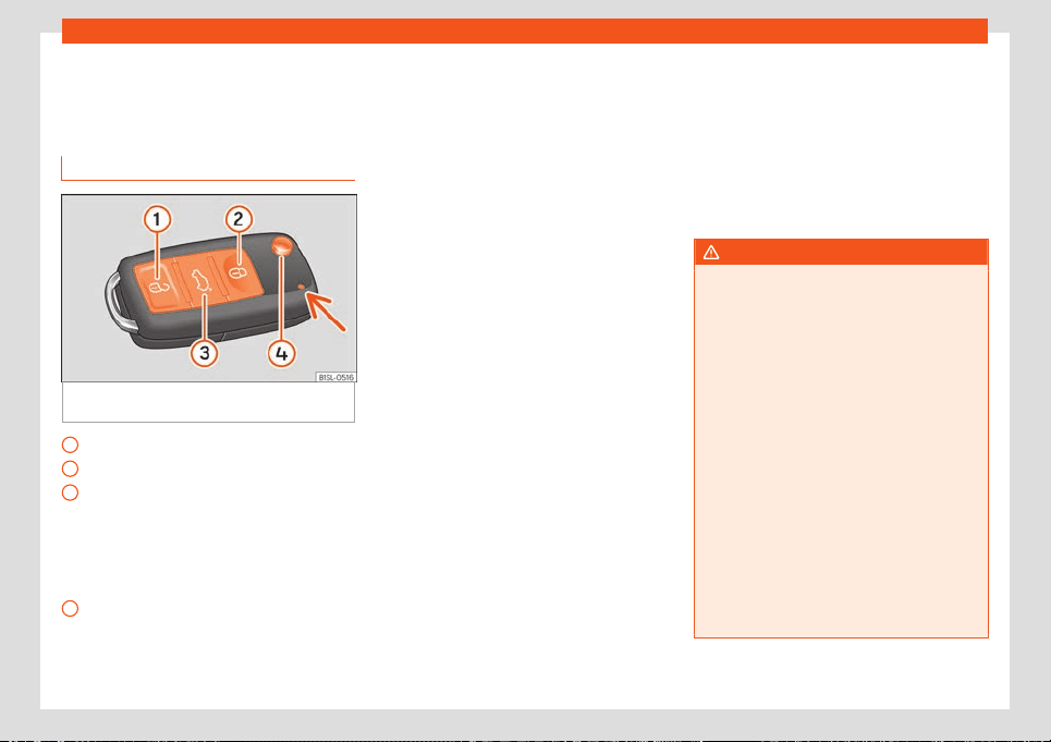
Opening and closing
Opening and closing
Set of v
ehicl
e k
eys
Vehicle key
Fig. 63 Assignment of buttons on the remote
contr
ol k
ey.
Unlock the vehicle
L
ock the v
ehicl
e
Unlock only the rear lid. Press the button
until all the turn signals on the vehicle
flash briefly. You have 2 minutes to open
the rear lid. Once this time has passed, it
will lock again. In addition, the lamp on
the key flashes.
Folding the key shaft in and out
With the vehicle key the vehicle may be
locked or unlocked remotely
›››
page 69.
1
2
3
4
The vehicle key includes an emitter and bat-
t
ery. The r
eceiv
er is in the interior of the vehi-
cle. The range of the vehicle key with remote
control and new battery is several metres
around the vehicle.
If it is not possible to open or close the vehicle
using the remote control key, this should be
re-synchronised
›››
page 69 or the battery
changed
›››
page 68.
Different keys belonging to the vehicle may
be used.
Control lamp on the vehicle key
When a button on the vehicle key is pressed,
the control lamp flashes
›››
Fig. 63 (arrow)
once briefly, but if the button is held down for
a longer period the control lamp flashes sev-
eral times, such as in convenience opening.
If the vehicle key control lamp does not light
up when the button is pressed, replace the
key's battery
›››
page 68.
Spare key
To obtain a spare key and other vehicle keys,
the vehicle chassis number is required.
Each new key contains a microchip which
must be coded with the data from the vehicle
electronic immobiliser. A vehicle key will not
work if it does not contain a microchip or the
microchip has not been encoded. This is also
true for keys which are specially cut for the
vehicle.
The vehicle keys or new spare keys can be
obtained from a SEAT Official Service, a spe-
cialised workshop or an approved key service
qualified to create this kind of key.
New keys or spare keys must be synchronised
before use
›››
page 69.
WARNING
●
Never l
eave children or disabled persons
in the vehicle. In case of emergency, they
may not be able to leave the vehicle or
manage on their own.
●
An uncontrolled use of the key could start
the engine or activate any electric equip-
ment (e.g. electric windows), causing risk
of accident. The doors can be locked using
the remote control key. This could become
an obstacle for assistance in an emergen-
cy situation.
●
Never forget the keys inside the vehicle.
An unauthorised use of your vehicle could
result in injury, damage or theft. Therefore
always take the key with you when you
leave the vehicle.
●
Never remove the key from the ignition if
the vehicle is in motion. Otherwise, the
steering could suddenly block and it would
be impossible to steer the vehicle.
»
67
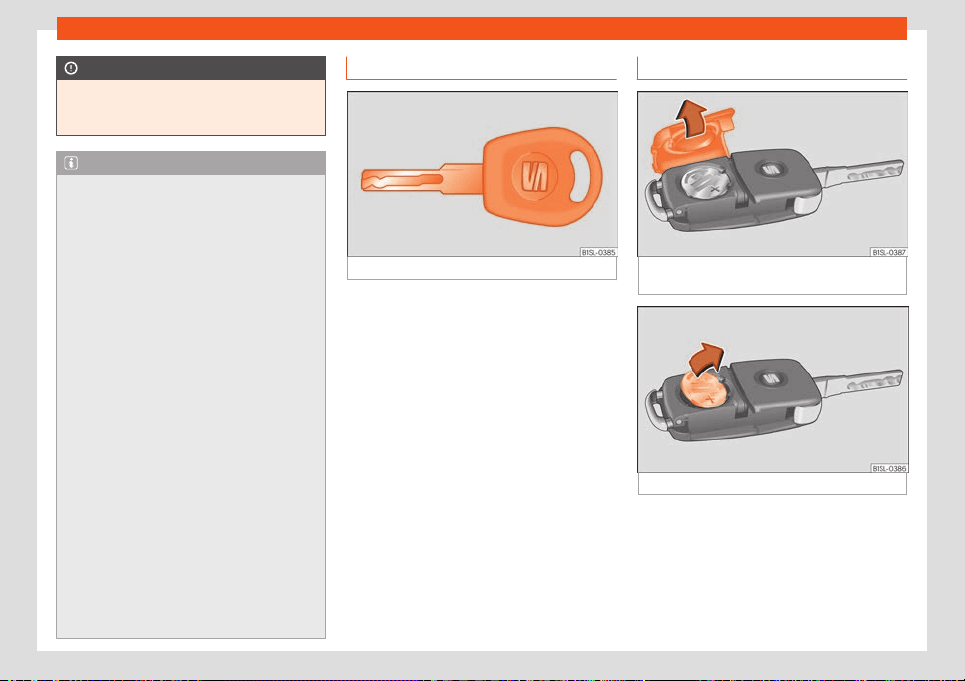
Operation
CAUTION
All of the vehicle keys contain electronic
components. Protect them fr
om damage,
impacts and humidity.
Note
●
Only use the key button when you r
equire
the corresponding function. Pushing the
button unnecessarily could accidentally
unlock the vehicle or trigger the alarm. It is
also possible even when you are outside
the radius of action.
●
Key operation can be greatly influenced
by overlapping radio signals close to the
vehicle working in the same range of fre-
quencies, for example, radio transmitters or
mobile telephones.
●
Obstacles between the remote control
and the vehicle, bad weather conditions
and discharged batteries can considerably
reduce the range of the remote control.
●
If the buttons of the vehicle key are
pressed or one of the central locking but-
tons
›››
page 71 is pressed repeatedly in
short succession, the central locking brief-
ly disconnects as protection against over-
loading. The vehicle is then unlocked. Lock
it if necessary.
●
Spare remote control keys are available
at your Technical Service, where they must
be matched to the locking system.
●
Up to five remote control keys can be
used.
Vehicle mechanical key
Fig. 64
Vehicle mechanical key
The vehicle key set may include a mechani-
cal k
ey
›
›
›
Fig. 64.
Duplicate keys
To obtain a spare key and other vehicle keys,
the vehicle chassis number is required.
Each new key must contain a microchip and
be coded with the data from the vehicle elec-
tronic immobiliser. A vehicle key will not work
if it does not contain a microchip or the mi-
crochip has not been encoded. This is also
true for keys cut for the vehicle.
The vehicle keys or new spare keys can be
obtained from a SEAT dealership, a special-
ised workshop or an approved locksmith
qualified to create them.
To change the battery
Fig. 65
Vehicle key: opening the battery com-
partment co
v
er
.
Fig. 66
Vehicle key: removing the battery.
SEAT recommends you ask a specialised
w
orkshop t
o r
eplace the battery.
The battery is located to the rear of the vehi-
cle key, under a cover.
68
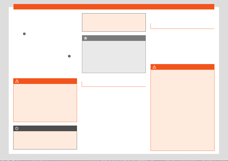
Opening and closing
Changing the battery
●
Unfold the vehicle key blade
›
›
›
page 67.
●
Remove the cover from the back of the ve-
hicle key
›››
Fig. 65 in the direction of the ar-
row
›››
.
●
Extract the battery from the compartment
using a suit
abl
e thin ob
ject
›››
Fig. 66.
●
Place the new battery in the compartment
as shown
›››
Fig. 66, pressing in the opposite
direction to that shown by the arrow
›››
.
●
Fit the cover as shown
›
›
›
Fig. 65, pressing it
onto the vehicle key casing in the opposite di-
rection to that shown by the arrow until it
clicks into place.
WARNING
Swallowing a battery with a 20 mm diame-
ter or any other button batt
ery can cause
serious and even fatal injuries within a very
short time.
●
Keep the vehicle key and key fobs with
batteries out of reach of children.
●
If you suspect that someone may have
swallowed a battery, seek immediate med-
ical attention.
CAUTION
●
If the battery is not changed correctly,
the v
ehicle key may be damaged.
●
Use of unsuitable batteries may damage
the vehicle key. For this reason, always re-
place the dead battery with another of the
same voltage
, size and specifications.
●
When fitting the battery, check that the
polarity is correct.
For the sake of the environment
The batteries used by the remote control of
the ignition k
ey of your vehicl
e may contain
perchlorate. This may involve special han-
dling instructions. Take into account the le-
gal provisions regarding the handling and
disposal of these batteries. We recommend
ordering this service from a SEAT dealer or
a specialised company.
Synchronize the vehicle key
If the butt
on is pr
essed fr
equently outside
of the vehicle range, it is possible that the ve-
hicle can no longer be locked or unlocked us-
ing the key. In this case, the key must be re-
synchronised as described below:
●
Unfold the vehicle key blade
›››
page 67.
●
Press the button on the vehicle key. For
this, it must remain with the vehicle.
●
Open the vehicle within one minute using
the key shaft.
●
Turn on the ignition using the vehicle key.
The key has been synchronised.
Central locking
Introduction
Central locking functions correctly when all
the doors and the rear lid are corr
ectly shut. If
the driver door is open, the vehicle cannot be
locked with the key.
The battery of an unlocked vehicle parked for
a long period (e.g. in a private garage) may
run down and fail to start the motor.
WARNING
The incorrect use of the central locking
system may cause serious injuries.
●
The central l
ocking system will lock all
doors. A vehicle locked from the inside can
prevent any non-authorised individual from
opening the doors and accessing the vehi-
cle. Nevertheless, in case of emergency or
accident, locked doors will complicate ac-
cess to the vehicle interior to help the pas-
sengers.
●
Never leave children or disabled people
alone in the vehicle. The central locking
button can be used to lock all the doors
from within. Therefore, passengers will be
locked inside the vehicle. Individuals locked
in the vehicle can be exposed to very high
or very low temperatures.
●
Depending on the time of the year, tem-
peratures inside a locked and closed vehi-
cle can be extremely high or extremely low
»
69
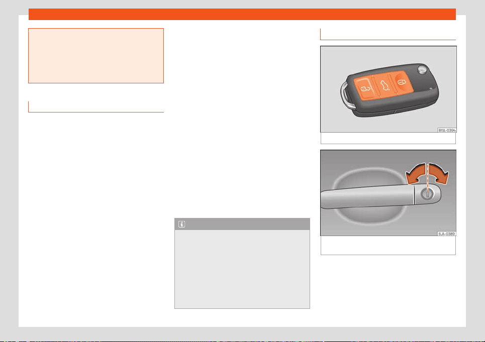
Operation
resulting in serious injuries and illness or
even death, par
ticularly for young children.
●
Never leave individuals locked in a closed
and locked vehicle. In case of emergency,
they may not be able to exit the vehicle by
themselves or get help.
Description
Central locking allows all doors, the rear lid
and the tank flap t
o be centrally locked and
unlocked:
●
From outside, using the vehicle key
›››
page 70.
●
From inside, by pushing the central locking
button
›››
page 71.
The central locking system can be activated
or deactivated at a specialised workshop.
In case of a vehicle key fault or central lock-
ing system fault, all doors can be locked or
unlocked manually.
Self-locking system to prevent involuntary
unlocking
It is an anti-theft system and prevents the un-
intentional unlocking of the vehicle. If the ve-
hicle is unlocked and none of the doors (in-
cluding the boot) are opened within 30 sec-
onds, it re-locks automatically.
Turn signals
The turn signals will flash twice when the ve-
hicle is unlocked and once when the vehicle
is locked.
If it does not flash, this indicates that one of
the doors, the rear lid or the bonnet is not
closed correctly.
Accidental lock-out
The central locking system prevents you from
being locked out of the vehicle in the follow-
ing situations:
●
If the driver door is open, the vehicle cannot
be locked with the central locking switch
›››
page 71.
Lock the vehicle with the remote control key,
when all the doors and the rear lid have been
closed. This prevents the accidental locking
of the vehicle.
Note
●
Never l
eave any valuable items in the ve-
hicle unattended. Even a locked vehicle is
not a safe.
●
If the LED on the driver door sill lights up
for about 30 seconds when the vehicle is
locked, the central locking system is not
working properly. You should have the fault
repaired at a SEAT Official Service or spe-
cialised workshop.
Unlock and lock from the outside
Fig. 67
Remote control key: buttons.
Fig. 68
Driver-side door handle with lock cyl-
inder
.
Unlock and lock using the remote control
●
Lock: press the
butt
on
›
›
›
Fig. 67.
●
Locking the vehicle without the “Safe” se-
curity system: push the
button again and
hold for 2 seconds.
●
Unlock: press the
›››
Fig. 67 button.
70
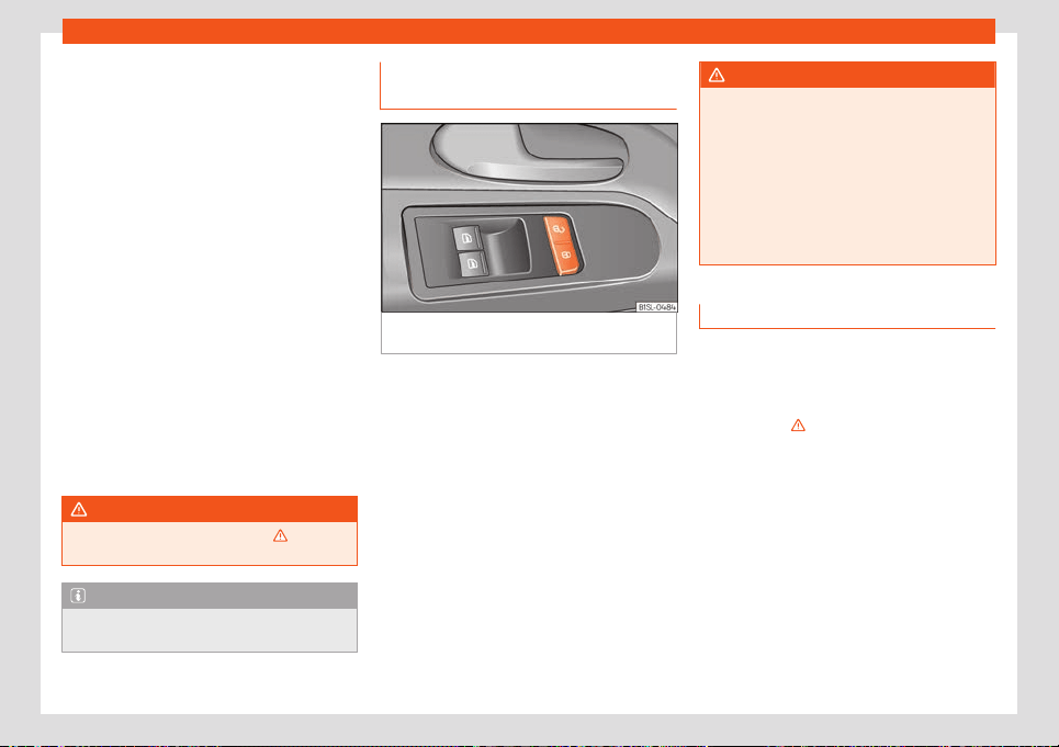
Opening and closing
●
Unl
ocking the r
ear lid: hol
d down the
button for at least 1 second.
Attention: depending on the central locking
function set by a specialised workshop, to un-
lock all the doors and the rear lid it will be
necessary to press the button twice.
Unlock and lock in the driver's door lock
cylinder
●
Lock the doors and rear lid: insert the key
into the lock cylinder and turn it clockwise.
●
Unlock the doors and rear lid: insert the key
into the lock cylinder and turn it anticlock-
wise.
The vehicle will be locked again automatical-
ly if you do not open one of the doors or the
rear lid within 30 seconds after unlocking the
car. This function prevents the vehicle from
remaining unlocked if the unlocking button is
pressed by mistake. This does not apply if you
press the button for at least one second.
WARNING
Observe the safety warnings
›››
in Lock-
ing system “Safe”* on page 7
2.
Note
Do not use the remote control key until the
vehicle is visibl
e.
Unlocking and locking from the in-
side
Fig. 69
On the driver’s door: central locking
butt
ons.
●
Lock: press the butt
on
›
›
›
Fig. 69.
●
Unlock: press the
›››
Fig. 69 button.
Please note the following when using the
central locking switch to lock your vehicle:
●
The “Safe” security system will not activate
●
It is not possible to open the doors or the
rear lid from the outside (for safety reasons,
e.g. when stopped at traffic lights).
●
You can open the doors individually from
the inside by pulling the inside door handle. If
necessary, pull the door release lever twice.
●
In the event of an accident in which the air-
bags inflate, doors locked from the inside will
be automatically unlocked to facilitate ac-
cess and assistance.
WARNING
●
The central locking s
witch also works
with the ignition switched off, except when
the “safe” system is activated.
●
The central locking switch does not oper-
ate if the vehicle is locked from the outside
and the security system is switched on.
●
Locked doors could delay assistance in
an emergency. Do not leave anyone, espe-
cially children, in the vehicle.
Locking system “Safe”*
When the vehicle is locked, the “Safe” securi-
t
y syst
em puts the door handl
es out of opera-
tion and makes it difficult for unauthorized
people to enter. The doors cannot be opened
from inside
›››
.
Depending on the v
ehicl
e
, when switching the
ignition off, a warning may be displayed on
the instrument panel display stating that the
“Safe” security system is activated.
Lock the vehicle and activate the “Safe”
security system.
●
Press the locking button once on the ve-
hicle key.
»
71
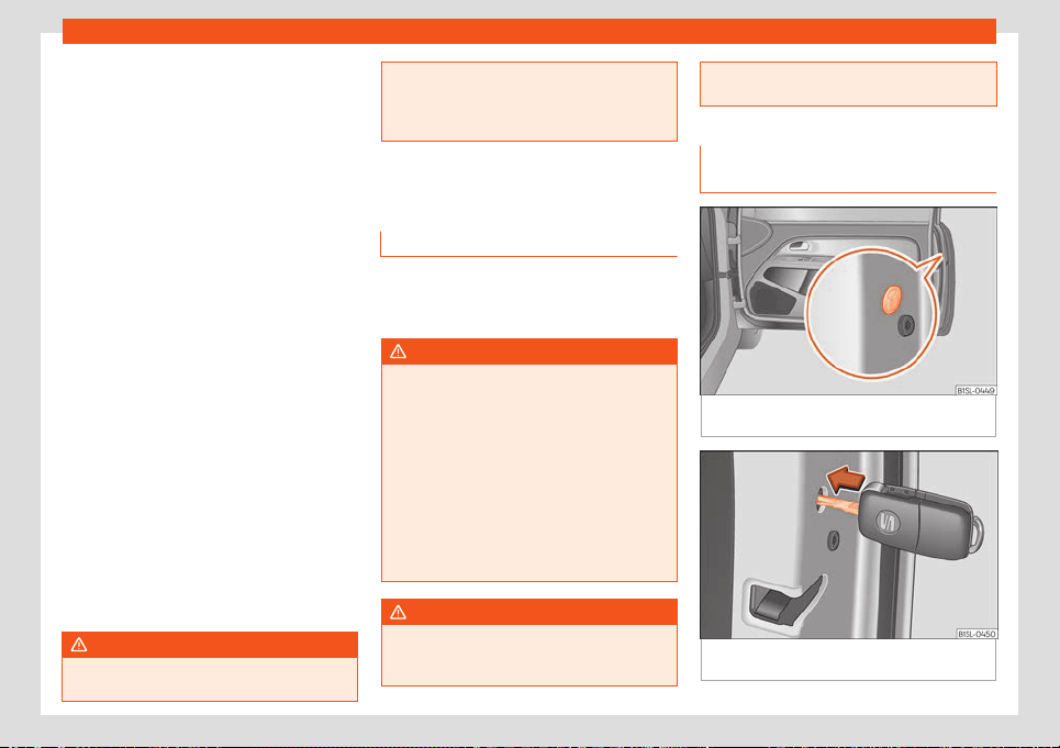
Operation
Lock the vehicle without activating the
“Saf
e” syst
em.
●
Pr
ess the locking button on the vehicle
key twice.
When the “Safe” security system is disa-
bled, the following needs to be taken into
account:
●
The vehicle can be opened and unlocked
from the inside using an inside door handle.
“Safe” status
On the driver door, there is warning lamp visi-
ble from outside the vehicle through the win-
dow which shows the “Safe” system status.
We will know that “Safe” system is activated
by the flashing warning lamp.
●
“Safe” activated: the warning lamp flashes
for about 2 seconds at short intervals; then,
more slowly.
●
“Safe” deactivated: the warning lamp
flashes for about 2 seconds and stops. After
30 seconds, the LED flashes again.
●
Locking system fault: the lamp flashes for
about 2 seconds at short intervals. Subse-
quently, the light will remain switched on for
about 30 seconds.
WARNING
Do not leave anyone (especially children)
in the vehicle if it is l
ocked from the outside
and the “Safe” security system* is activa-
ted, as the doors and windows cannot then
be opened fr
om the inside. Locked doors
could delay assistance in an emergency.
Doors
Introduction
The doors and rear lid can be locked man-
ually and partially opened, for ex
ample if the
key or the central locking is damaged.
WARNING
If a door is not correctly closed, it could
open unexpectedly when driving and cause
serious injuries.
●
Al
ways stop immediately and close the
door.
●
When closing, ensure that the door has
closed correctly. A closed door should be
flush with the corresponding parts of the
bodywork.
●
Open and close doors only when nobody
is in the way of the door.
WARNING
A door held open by its retainer could be
blown cl
osed by the wind or close if the ve-
hicle is on a hill, causing injury.
●
When opening and closing doors, alw
ays
use the door handle.
Locking the passenger door man-
ually
Fig. 70
On the front of the passenger door:
emer
gency l
ock
, hidden by a rubber seal.
Fig. 71 Emergency locking of the vehicle using
the v
ehicl
e k
ey
72
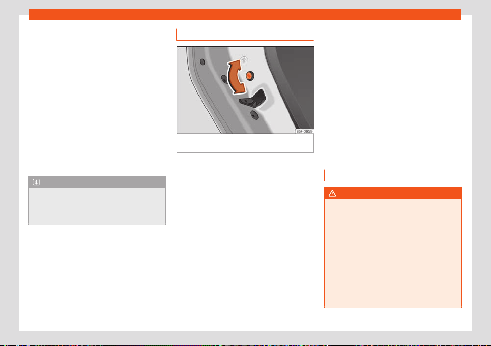
Opening and closing
The passenger door can be manually locked.
●
Open the door.
●
Remove the rubber cap to the front of the
door
. The rubber cap is mark
ed with a l
ock
symbol
›››
Fig. 70.
●
Unfold the key shaft if necessary
›››
page 67.
●
Insert the key shaft horizontally into the
opening and moved the coloured lever for-
ward
›››
Fig. 71.
●
Replace the rubber cap and close the door.
●
Check if the door is locked.
●
Have the vehicle checked by a specialised
workshop.
Note
The doors can be opened and unlocked in-
dividually from the inside by pulling the
door handle
. To open, pull the inner door
release lever twice
›››
page 69.
Childproof locks
Fig. 72
Childproof lock on the left hand side
door
.
The childproof lock prevents the rear doors
fr
om being opened fr
om the inside
. This sys-
tem prevents minors from opening a door ac-
cidentally while the vehicle is running.
This function is independent of the vehicle
electronic opening and locking systems. It
only affects rear doors. It can only be activa-
ted and deactivated manually, as described
below:
Activating the childproof lock
–
Unlock the vehicle and open the door in
which you wish to activate the childproof
lock.
–
With the door open, rotate the groove in the
door using the ignition key, clockwise for
the left hand side doors
›››
Fig. 72 and anti-
clockwise for the right hand side doors.
Deactivating the childproof lock
–
Unlock the vehicle and open the door
whose childproof lock you want to deacti-
vate.
–
With the door open, rotate the groove in the
door using the ignition key, anti-clockwise
for the left hand side doors
›››
Fig. 72 and
clockwise for the right hand side doors.
Once the childproof lock is activated, the
door can only be opened from the outside.
Rear lid
Introduction
WARNING
Careless and unsuitable locking, opening
and closing of the rear lid can cause acci-
dents and serious injury.
●
The r
ear lid must not be opened when the
reverse or rear fog lights are lit. This may
damage the tail lights.
●
Do not close the rear lid by pushing it
down with your hand on the rear window.
The glass could smash. Risk of injury!
●
Ensure the rear lid is locked after closing
it. If not, it may open unexpectedly while
driving.
»
73
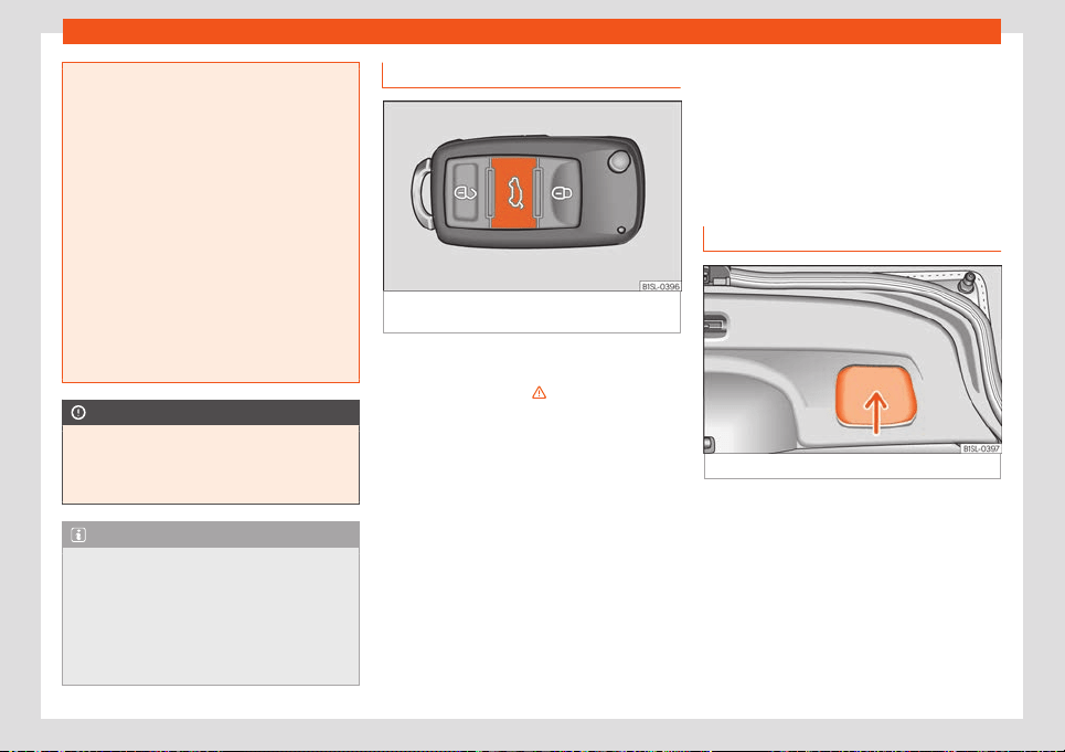
Operation
●
Closing the rear lid without observing
and ensuring it is cl
ear could cause serious
injury to you and to third parties. Make sure
that no one is in the path of the rear lid.
●
Never drive with the rear lid open or half-
closed, exhaust gases may penetrate into
the interior of the vehicle. Danger of poi-
soning!
●
Never leave the vehicle unattended or al-
low children to play inside or next to it, es-
pecially if the rear lid is open. Children
could enter the luggage compartment,
close the rear lid and become trapped. A
locked vehicle can reach extremely high
and low temperatures, depending on the
time of year, thus causing serious injuries,
illness or even death.
CAUTION
Before opening or closing the rear lid, make
sure that there is enough space t
o open or
close it, e.g. when pulling a trailer or in a
garage.
Note
●
Before cl
osing the rear lid, make sure that
the key has not been left inside the luggage
compartment.
●
At outside temperatures of less than 0°C
(+32°F), the pressurised gas struts cannot
always automatically lift the rear lid. In this
case, open the rear lid manually.
Opening the rear lid
Fig. 73
On the vehicle key: button to unlock
and open the r
ear lid.
If bicycles are attached to a rack on the boot
hat
ch, f
or e
xample, in some cases, it may not
open automatically
›››
in Introduction on
page 7
3
.
Opening with centr
al locking
●
Press the button on the vehicle key
›››
Fig. 73 for about one second to unlock the
rear lid.
●
OR: Press the button on the vehicle key
until the rear lid opens automatically several
centimetres.
●
Open the rear lid using the handle.
Opening with the key without remote con-
trol
●
Insert the vehicle key into the lock cylinder
of the driver door and turn the key in an anti-
clockwise direction
›››
page 69.
●
Open the rear lid using the handle.
Closing the rear lid
Fig. 74 Rear lid open: space for pulling.
Closing the rear lid
●
Grab the handgrip inside the rear lid
›
›
›
Fig. 74 (arrow).
●
Push the rear lid downwards until it locks in-
to place in the lock.
●
Ensure that it is correctly closed by pulling
on it firmly.
74
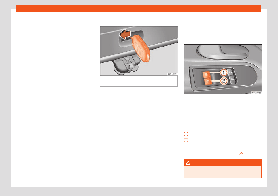
Opening and closing
Locking the rear lid with central locking*
If you unl
ock the v
ehicl
e without opening any
doors or the rear lid, it will lock again auto-
matically after about 30 seconds. This func-
tion prevents the vehicle from remaining un-
locked if the unlocking button is pressed by
mistake.
Locking is only possible when the rear lid is
correctly and fully closed.
●
The rear lid is also locked by a central lock-
ing.
●
If the vehicle rear lid is locked or unlocked
using the button of the vehicle key, when it
is closed again it will lock automatically.
●
A closed but not locked rear lid will lock au-
tomatically at a speed above about 9 km/h
(6 mph).
Locking the rear lid with the vehicle me-
chanical key
Locking is only possible when the rear lid is
correctly and fully closed.
●
Insert the vehicle key into the lock cylinder
of the driver door and turn the key in a clock-
wise direction
›››
page 69.
Emergency unlocking of the rear lid
Fig. 75
From the luggage compartment: emer-
gency unl
ocking of the r
ear lid.
●
If necessary, fold the rear seat bench back-
r
est f
orw
ard
›››
page 88.
●
Remove equipment to access the inside of
the rear lid.
●
Unfold the key shaft
›››
page 67.
●
Insert the key shaft into the rear lid opening
›››
Fig. 75 and press the release lever in the
direction of the arrow to unlock the rear lid.
Window controls
Electrically opening and closing
the windows
Fig. 76
Detail of the driver's door: window con-
tr
ol
s.
●
Opening the window: press the button .
●
Closing the window: pull the button .
Butt
ons on the driv
er door
Windo
w on the front left door
Window on the front right door
Always close the windows fully if you park the
vehicle or leave it unattended
›››
.
WARNING
Incorrect use of the electric windows can
result in injury.
»
1
2
75
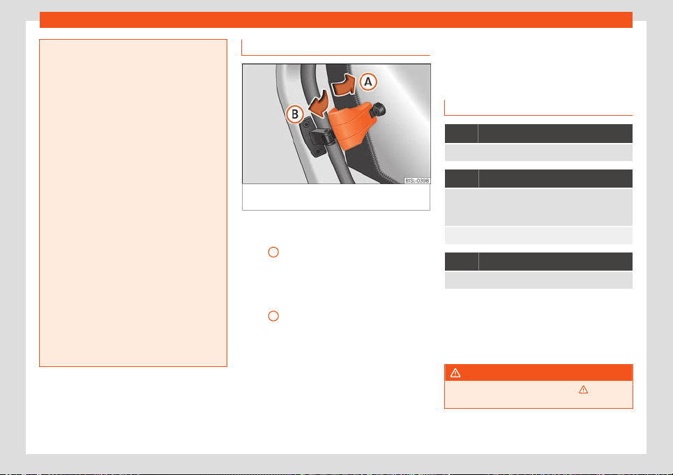
Operation
●
Never cl
ose the rear lid without observing
and ensuring it is clear, to do otherwise
could cause serious injury to you and third
parties. Make sure that no one is in the path
of a window.
●
If the ignition is switched on, the electric
equipment could be activated with risk of
injury, for example, in the electric windows.
●
The doors can be locked using the re-
mote control key. This could become an
obstacle for assistance in an emergency
situation.
●
Therefore always take the key with you
when you leave the vehicle.
●
The electric windows will work until the
ignition has been switched off and one of
the front doors has been opened.
●
If necessary, use the safety switch to dis-
able the rear electric windows. Make sure
that they have been disabled.
●
For safety reasons, you should only use
the remote control open and close func-
tions within about 2 metres of the vehicle.
To avoid injuries, always keep an eye on the
windows when pressing the button to close
them. The windows stop moving as soon as
the button is released.
Side opening rear windows
Fig. 77
Lever to open and close the rear win-
do
w
Opening
●
Pull the unlocking lever in the direction of
arr
o
w
A
and press it out, until the lever en-
gages.
Cl
osing
●
Pull the unl
ocking l
ever in the direction of
arrow
B
and press the lever in until it engag-
es.
Lights
V
ehicl
e lighting
Contr
ol lamps
It lights up
Rear fog light switched on
›››
page 78.
It lights up
Left or right turn signal.
The control lamp fl
ashes twice as fast when a turn
signal is faulty.
Hazard warning lights on
›››
page 80.
It lights up
Main beam on or flasher on
›››
page 78.
Several warning and control lamps light up
f
or a f
e
w seconds when the ignition is switch-
ed on, signalling that the function is being
verified. They will switch off after a few sec-
onds.
WARNING
Observe the safety warnings
›››
in Con-
trol and warning l
amps on page 66.
76
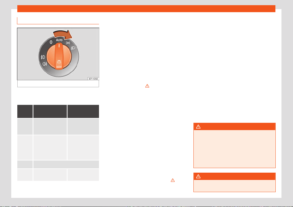
Lights
Headlight switch
Fig. 78
Dash panel: lights control.
●
Turn the switch to the required position
›
›
›
Fig. 78.
Sym-
bol
Ignition switch-
ed off
Ignition is
switched on
F
og lights, dipped
beam and side
lights off.
Light off or day-
time driving light
on.
The “Coming
home” and “Leaving
home” guide lights
may be swit
ched
on.
Automatic control
of dipped beam
and daytime run-
ning light.
Side light on.
Dipped beam head-
light off
Dipped beam
s
witched on.
The driver is personally responsible for the
corr
ect use and adjustment of the lights in all
sit
uations.
Aut
omatic dipped beam headlight control
*
The automatic dipped beam control is merely
intended as an aid and is not able to recog-
nise all driving situations.
When the light switch is in position , the
vehicle lights and the instrument panel and
switch lighting switch on automatically in the
following situations
›››
:
●
The photo sensor detects d
arkness
, f
or ex-
ample, when driving through a tunnel. They
switch off when adequate lighting is detec-
ted.
●
The rain sensor detects rain and activates
the wipers. They switch off when the wipers
have not been activated for a few minutes.
Daytime running lights
The daytime driving light consists of individu-
al lights in the front headlamps.
The DRL LED headlight running lights consist
of LED lights. If an LED light fails, go to an au-
thorised workshop for its replacement.
When the daytime driving light is switched on,
only the individual lights come on
›››
.
The daytime running lights turn on every time
the ignition is s
wit
ched on, if the s
witch is in
position or , according to the level of ex-
terior lighting.
When the light switch is in position , a light
sensor automatically switches dipped beam
on and off (including the control and instru-
ment lighting) or the daytime running lights
depending on the level of exterior lighting.
Audible warnings to advise the driver that
the lights have not been switched off
If the key is not in the ignition and the driver
door is open, an audible warning signal is
heard in the following cases: this will remind
you to turn the light off.
●
When the parking light is on
›››
page 78.
●
When the light switch is in position or .
WARNING
If the road is not well lit and other road
users cannot see the vehicle w
ell enough
or at all, accidents may occur.
●
The automatic dipped beam control
( ) only switches on the dipped beam
when there are changes in light conditions
but not, for example, when it is foggy.
WARNING
The side lights or daytime running lights
are not bright enough to illuminat
e the road
»
77
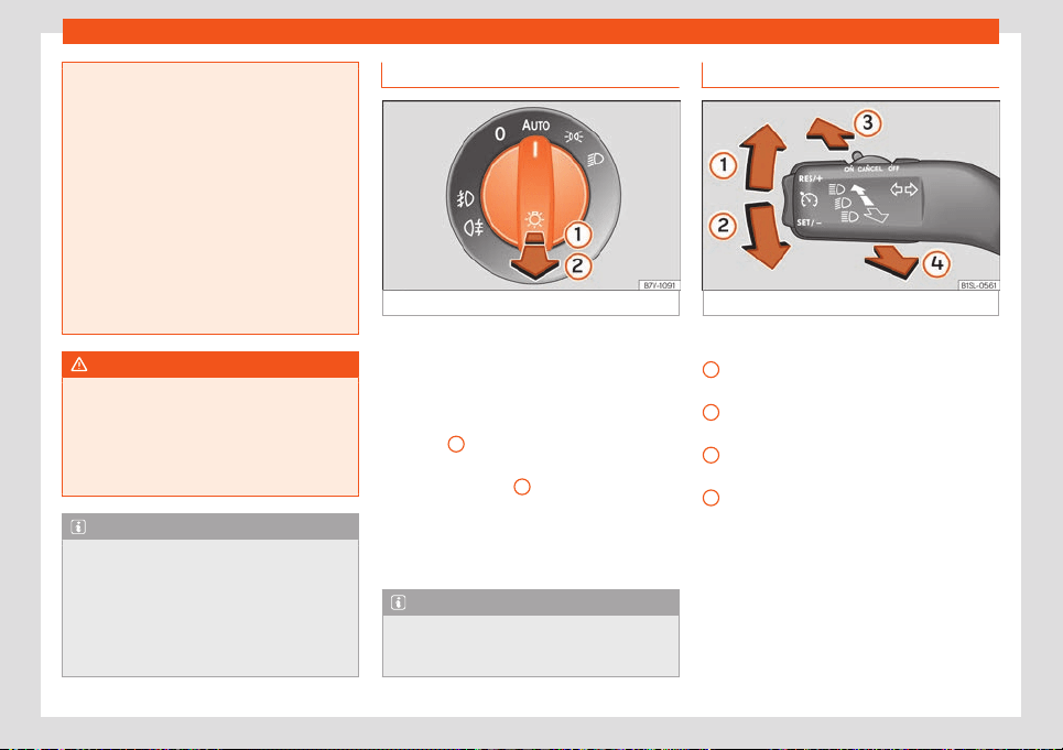
Operation
ahead and to ensure that other road users
are able t
o see you.
●
Always use your dipped beam head
lights if it is raining or if visibility is poor.
●
Never drive with daytime lights if the road
is not well lit due to weather or lighting
conditions.
●
On vehicles with rear lights with bulbs,
when activating the daytime running light
the rear lights are not switched on. A vehi-
cle which does not have the rear lights on
may not be visible to other drivers in the
darkness, in the case of heavy rain or in
conditions of poor visibility.
WARNING
If the headlights are set too high and not
used correctly, there is a risk of dazzling or
distr
acting other road users. This could re-
sult in a serious accident.
●
Always make sure that the headlights are
correctly adjusted.
Note
●
The legal requir
ements regarding the use
of vehicle lights in each country must be
observed.
●
The dipped beam headlights will only
work with the ignition on. The side lights
come on automatically when the ignition is
turned off.
Fog lights
Fig. 79
Dash panel: lights control.
The warning lamps or al
so sho
w
, on the
light switch or instrument panel, when the
front fog lights are on.
●
Turning on the front fog lights* : pull the
light switch out to its first click position
›››
Fig. 79
1
, from positions , or .
●
Turning on the rear fog light : pull the
light s
wit
ch fully out
2
from position , or
. This contr
ol has only one position in v
e-
hicles without fog lights.
●
To switch off the fog lights, press the light
switch or turn it to position .
Note
The rear fog light can dazzle drivers behind
you. You should use the r
ear fog light only
when visibility is very poor.
Turn signal and main beam lever
Fig. 80
Turn signal and main beam lever.
More the lever to the required position:
Right t
urn light or right
-hand parking light
(ignition s
witched off).
Left turn light or left-hand parking light
(ignition switched off).
Main beam on: control lamp lit up on
the instrument panel.
Light flash: on with the lever pushed. Con-
trol lamp lit up.
Push the lever all the way down to turn off the
corresponding function.
Convenience turn signals
When the ignition is switched on, move the
lever as far as possible upwards or down-
wards and release the lever. The turn signal
will flash three times.
1
2
3
4
78
Lights
The convenience indicators can be deactiva-
t
ed at a Specialised w
orkshop
.
Parking light on both sides
●
Switch the ignition off.
●
Place the light switch in position .
●
Lock the vehicle from the outside.
In doing so, only the side lights of both head-
lights light up, and additionally the tail lights
will do so partially.
WARNING
Improper or lack of use of the turn signals,
or forgetting t
o deactivate them can con-
fuse other road users. This could result in a
serious accident.
●
Always give warning when you are going
to change lane, overtake or when turning,
activating the turn signal in good time.
●
As soon as you have finished changing
lane, overtaking or turning, switch the turn
signal off.
WARNING
Incorrect use of the headlights may cause
accidents and serious injury, as the main
beam may distract or dazzle other driv
ers.
Note
●
If the convenience turn signal
s are oper-
ating (three flashes) and the other conven-
ience turn signals are switched on, the ac-
tive part stops flashing and only flashes
once in the new part selected.
●
The turn signal only works when the igni-
tion is switched on. The hazard warning
lights also work when the ignition is switch-
ed off.
●
The main beam headlights can only be
switched on if the dipped beam headlights
are already on.
●
In cold or damp weather conditions, the
headlights, tail lights and turn signals may
mist up inside temporarily. This is normal
and in no way effects the useful life of the
vehicle lighting system.
“Coming home” and “Leav-
ing home” function
The “Coming home” and “Leaving home”
function lights up the v
ehicl
e
’s immediate
proximity when getting into and out of it in the
dark. When switched on, the front position
and dipped beam lights, tail lights and li-
cense plate light come on.
The “Leaving Home” is controlled by a photo-
sensor.
In the vehicle settings menu of the infotain-
ment system you can adjust the duration of
the light switch-off delay, and activate and
deactivate the function.
Activating the “Coming Home” function
●
Switch the ignition off.
●
Activate the headlight flashers for approxi-
mately 1 second.
When the driver door is opened, the “Coming
Home” lighting comes on. The delay in
switching off the headlights is counted from
when the last door or boot hatch is closed.
The “Coming Home” lighting turns off in
the following cases:
●
Automatically, once the headlight turn off
delay has elapsed.
●
Automatically, when a vehicle door or the
rear lid is still open 30 seconds after starting
the engine.
●
When the rotary light switch is turned to po-
sition
›››
page 77.
●
With the ignition is switched on.
Activating the “Leaving Home” function
●
Unlock the vehicle using the remote control.
●
The “Leaving Home” function is only activa-
ted when the light switch is in position
and the light sensor detects darkness.
»
79
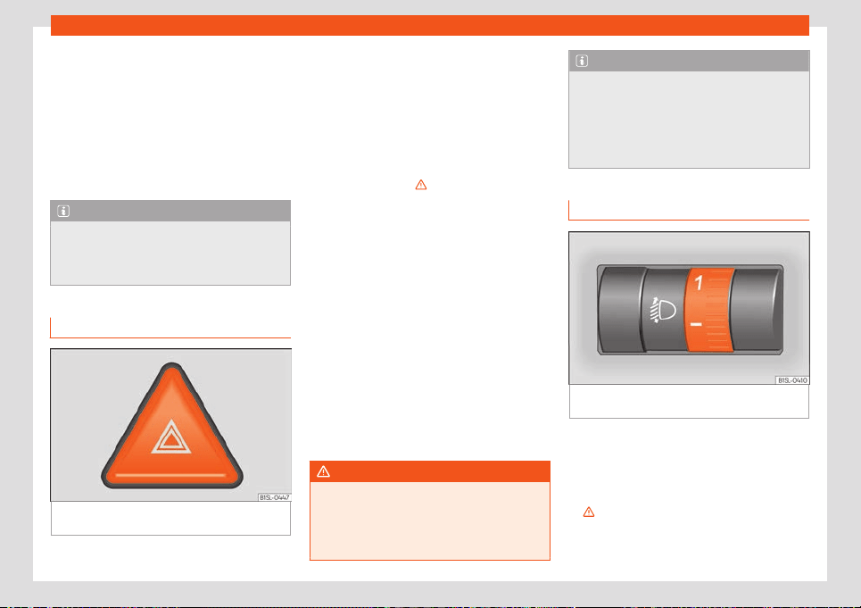
Operation
The “Leaving Home” lighting switches off
in the f
oll
o
wing cases:
●
Automatically, when the “Leaving Home”
delay period ends (default 30 sec).
●
When the vehicle is locked using the remote
control.
●
When the light switch is turned to position .
●
With the ignition is switched on.
Note
To activate the “Coming Home” and “Leav-
ing Home” function, the rotary light s
witch
must be in position and the light sensor
must detect darkness.
Hazard warning lights
Fig. 81
Dash panel: hazard warning lights
s
wit
ch
The hazard warning lights are used to draw
the att
ention of other r
oad users t
o your vehi-
cle in emergencies.
If your vehicle breaks down:
1. Park your vehicle at a safe distance from
moving traffic.
2. Press the button to switch on the hazard
warning lights
›››
.
3. Switch the ignition off.
4. Apply the handbrake.
5. Move the selector lever to position P.
6. Use the warning triangle to draw the at-
t
ention of other r
oad users t
o your vehicle.
7. Always take the vehicle key with you when
you leave the vehicle.
All turn signals flash simultaneously when the
hazard warning lights are switched on. The
two turn signal turn signal lamps and the
turn signal lamp in the switch will flash at
the same time. The simultaneous hazard
warning lights also work when the ignition is
switched off.
WARNING
The risk of an accident increases if your ve-
hicle breaks do
wn. Always use the hazard
warning lights and a warning triangle to
draw the attention of other road users to
your stationary vehicle.
Note
●
The battery will run down if the haz
ard
warning lights are left on for a long time,
even if the ignition is switched off.
●
The use of the hazard warning lights de-
scribed here is subject to the relevant stat-
utory requirements.
Light range control
Fig. 82
Next to the steering wheel: headlight
r
ange contr
ol
.
The headlight range control
›
›
›
Fig. 82 is
modified according to the value of the head-
light beam and the vehicle load status. This
offers the driver optimum visibility and the
headlights do not dazzle oncoming drivers
›››
.
The headlights can only be adjust
ed when
the dipped beam is s
wit
ched on.
80
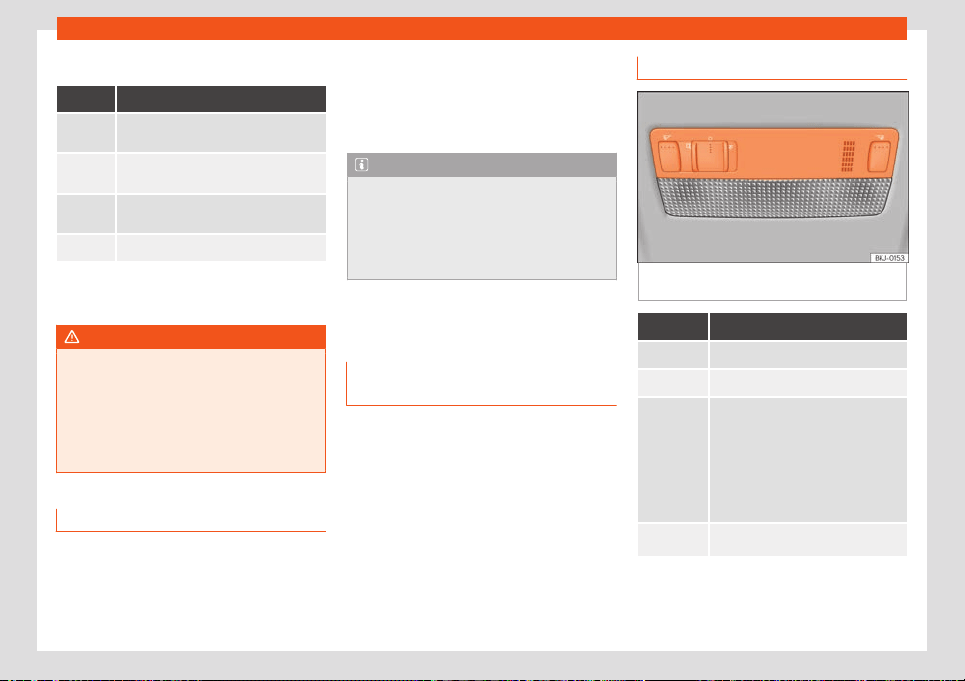
Lights
To reset, turn switch
›
›
›
Fig. 82:
Value Vehicle load status
a)
Two front occupants, luggage compart-
ment empty
All seats occupied, luggage compart-
ment empty
All seats occupied, luggage compart-
ment full.
Driver only, luggage compartment full
a)
If the vehicle load does not correspond to those
sho
wn in the t
abl
e, it is possible to select intermediary
positions.
WARNING
Heavy objects in the vehicle may mean
that the headlights dazzle and distract oth-
er driv
ers. This could result in a serious ac-
cident.
●
Adjust the light beam to the vehicle load
status so that it does not blind other driv-
ers.
Driving abroad
In those countries where vehicles drive on the
other side of the r
oad t
o the home country,
the asymmetric dipped beam may dazzl
e
drivers of oncoming vehicles.
For this reason, stickers may be needed to
cover the headlights when driving abroad.
For further information, please refer to a spe-
cialised workshop. SEAT recommends visiting
a technical service.
Note
The use of stickers to cover headlights is
only permitted ov
er a short period. To mod-
ify the direction of the headlamps more
permanently, please take the vehicle to a
specialised workshop. SEAT recommends
taking your car in for technical service.
Interior lights
Lighting of the instrument panel
,
displ
ays and s
witches
When the side lights or dipped beam head-
lights ar
e s
wit
ched on, the lighting for instru-
ments and controls lights up at a constant
brightness.
Interior and reading lights
Fig. 83
Detail of roof lining: front lighting of the
passenger compartment.
Knob Function
Switching off the reading light.
Turning the interior lights on or off.
Door contact connection.
The int
erior lights come on automati-
cally when you unl
ock the vehicle,
open a door or remove the key from
the ignition.
The light goes out a few seconds after
closing all the doors, when locking the
vehicle or connecting the ignition.
/
Turning the reading light on and off
Luggage compartment lighting
The light is activ
at
ed when the r
ear lid is
open, even when the ignition and lights are
»
81
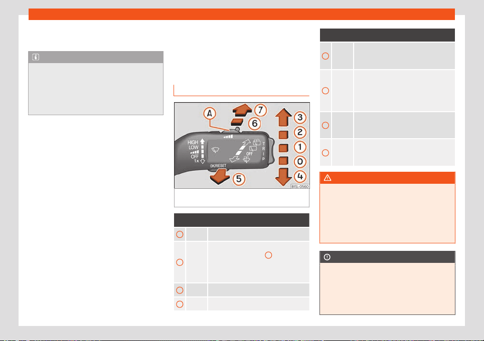
Operation
turned off. For this reason, ensure that the
r
ear lid is al
w
ays closed.
Note
If not all the vehicle doors are closed, the
interior lights will be swit
ched off after ap-
prox. 10 minutes, providing the ignition key
has been removed and the courtesy light
position selected. This prevents the battery
from discharging.
Visibility
Windscr
een wiper and r
ear
windo
w wiper systems
Window washer lever
Fig. 84 Operating the windscreen wiper and
r
ear wiper
.
More the lever to the required position:
0
Windscreen wipers off.
1
Wiper intervals.
Use control
››
›
Fig. 84
A
to set the in-
t
erv
al (v
ehicles without rain sensor), or
the sensitivity of the rain sensor
›››
page 83.
2
Slow wipe.
3
Continuous wipe.
More the lever to the required position:
4
Short wipe. Brief press, short clean.
Hold the le
ver down for more time to in-
crease the wipe frequency.
5
Windscreen washer. The windscreen
washer function is activated by push-
ing the lever towards the steering
wheel, and the wipers operate simulta-
neously.
6
Interval wipe for rear window. The wip-
er will wipe the window appro
ximately
every six seconds.
7
The rear window wash function is acti-
vated by pr
essing the lever, and the
rear wiper starts simultaneously.
WARNING
In cold conditions you should not use the
wash/wipe system unl
ess you have
warmed the windscreen with the heating
and ventilation system. The windscreen
washer fluid could otherwise freeze on the
windscreen and obscure your view of the
road.
CAUTION
If the ignition is switched off with the wind-
screen wipers active
, they complete their
wipe before returning to the rest position.
When switching the ignition back on, the
windscreen wiper will continue to operate
at the same wiping level. Ice, snow and
82
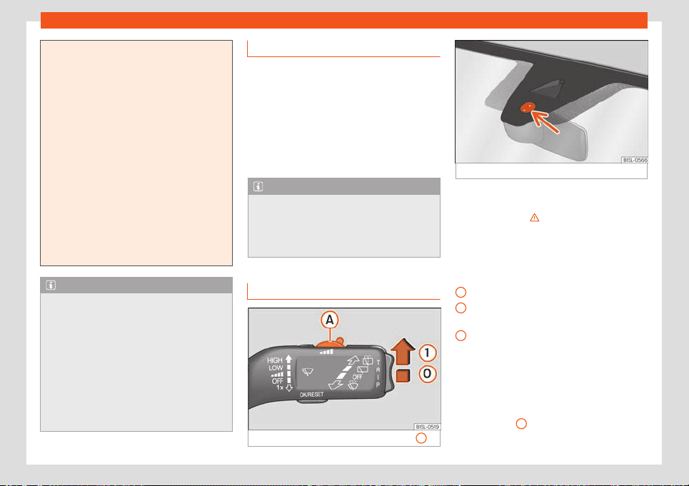
Visibility
other obstacles on the windscreen may
damage the wiper and the windscreen wip-
er motor
.
●
If necessary, remove snow and ice from
the windscreen wipers before starting your
journey.
●
Carefully lift the frozen windscreen wip-
ers from the glass. SEAT recommends a de-
icer spray for this operation.
●
Do not switch on the windscreen wipers if
the windscreen is dry. Cleaning with the
windscreen wipers while dry can cause
damage.
●
In icy conditions, always check that the
wiper blades are not frozen to the glass be-
fore using the wipers. In cold weather, it
may help to leave the vehicle parked with
the wipers in service position
›››
page 43.
Note
●
The windscreen and window wipers only
function when the ignition is s
witched on
and the bonnet or rear lid, respectively, are
closed.
●
The interval wipe speed varies according
to the vehicle speed. The faster the vehicle
is moving, the more often the windscreen is
cleaned.
●
The rear wiper is automatically switched
on when the windscreen wiper is on and the
car is in reverse gear.
Wiper functions
Windscreen wipers performance in differ-
ent situations
●
If the vehicl
e is stopped, the activated posi-
tion temporarily moves to the previous posi-
tion.
●
When wiping at intervals, the intervals vary
according to the speed. The higher the vehi-
cle speed the shorter the intervals.
Note
The wiper will try to wipe away any obsta-
cles that are on the windscr
een. The wiper
will stop moving if the obstacle blocks its
path. Remove the obstacle and switch the
wiper back on again.
Rain sensor*
Fig. 85 Wiper lever: adjust the rain sensor
A.
Fig. 86 Rain sensor sensitive surface
The rain sensor controls the frequency of the
windscr
een wiper int
erv
als, depending on the
amount of rain
›››
. The sensitivity of the rain
sensor can be adjust
ed manually. Manual
wipe
›
›
›
page 82.
Move the lever to the required position
›››
Fig. 85:
Rain sensor off.
Rain sensor on; automatic wipe if neces-
sary.
Setting sensitivity level of rain sensor
–
Set control to the right: high sensitivity.
–
Set control to the left: low sensitivity.
When the ignition is switched off and then
back on, the rain sensor stays on and starts
operating again when the windscreen wipers
are in position
1
and the vehicle is travelling
at mor
e than 16 km/h (
10 mph).
»
0
1
A
83
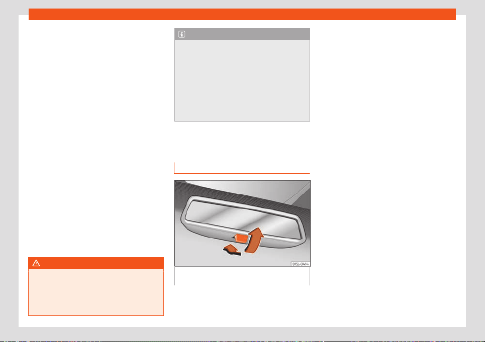
Operation
Modified behaviour of the rain sensor
P
ossibl
e causes of f
aults and mistaken read-
ings on the sensitive surface
›››
Fig. 86 of the
rain sensor include:
●
Damaged wipers: a film of water on the
damaged blades may lengthen the activa-
tion time, reduce the washing intervals or re-
sult in a fast and continuous wipe.
●
Insects: insects on the sensor may trigger
the windscreen wiper.
●
Salt on the road: in winter, salt spread on
the roads may cause an excessively long
wipe when the windscreen is almost dry.
●
Dirt: dry dust, wax, coating on glass (Lotus
effect) or traces of detergent (car wash) may
reduce the effectiveness of the rain sensor or
make it react more slowly, later or not at all.
●
Windscreen crack: the impact of a stone
will trigger a single wipe cycle with the rain
sensor on. Next the rain sensor detects the re-
duction in the sensitive surface area and
adapts accordingly. The behaviour of the
sensor will vary with the size of the damage
caused by the stone.
WARNING
The rain sensor may not detect enough rain
to swit
ch on the wipers.
●
If necessary, switch on the wipers man-
ually when water on the windscreen ob-
structs visibility.
Note
●
Clean the sensitive surf
ace of the rain
sensor regularly and check the blades for
damage
›››
Fig. 86 (arrow).
●
To remove wax and coatings, we recom-
mend a window cleaner containing alco-
hol.
●
Do not put stickers on the windscreen in
front of the rain sensor*. This may cause
sensor disruption or faults.
Mirrors
Int
erior mirr
or
Fig. 87
Manual anti-dazzle function for rear vi-
sion mirr
or
Manual anti-dazzle function for interior
r
ear vision mirr
or
●
Basic position: point the l
ever at the bottom
of the mirror forwards.
●
Pull the lever to the back to select the anti-
dazzle function
›››
Fig. 87.
84
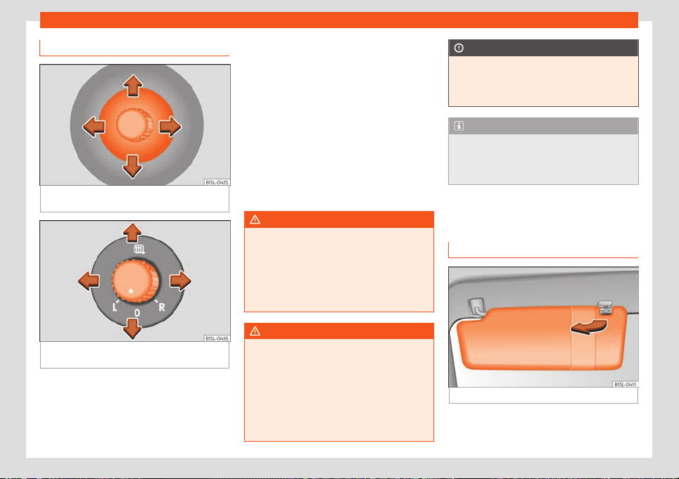
Visibility
Adjusting the exterior mirrors
Fig. 88
On the front doors: button to adjust the
mechanical e
xt
erior r
ear vision mirror.
Fig. 89 On the driver’s door: control to adjust
the el
ectric e
xt
erior rear view mirrors.
The exterior rear view mirrors are adjusted by
mo
ving the adjustment contr
ol
›
››
Fig. 88 or
the rotary control*
›››
Fig. 89.
By moving the control to the desired po-
sition, adjust the rear view mirrors on the
L/R
left side (L) and on the right side (R) in
the desired direction.
Depending on the equipment fitted on
the vehicle, the mirrors may be heated
according to the outside temperature.
Manually folding the exterior mirrors
Folding in the exterior mirrors and returning
them to their original position is possible
through a mechanical system. Carefully fold
the exterior rear vision mirror casing towards
the side window or pull it away from the win-
dow until it clicks into place.
WARNING
Convex or wide-angle* exterior mirrors
give a lar
ger field of vision. However, they
make objects look smaller and further
away than they really are. If you use these
mirrors to estimate the distance to vehicles
behind you when changing lane, you could
misjudge the distance. Risk of accident!
WARNING
Fold and unfold the exterior mirror, taking
care to av
oid injuries.
●
Only fold or unfold the exterior mirror
when there is no-one in the way of the mir-
ror.
●
When moving the mirror, take care not to
trap fingers between the mirror and the
mirror bracket.
CAUTION
Before washing the vehicle in an automatic
car wash, please mak
e sure to retract the
exterior mirrors to prevent them from being
damaged.
Note
If the electrical adjustment should fail to
operate
, both of the mirrors can be adjus-
ted by hand by lightly pressing the edge of
the mirror glass.
Sun protection
sun blind
Fig. 90
Sun visor on the driver side.
»
85
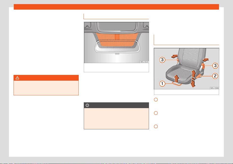
Operation
Options for adjusting driver and front pas-
senger sun visors
●
Lower the sun visor towards the wind-
scr
een.
●
The sun visor can be pull
ed out of its
mounting and t
urned towards the door.
●
Swing the sun visor towards the door, longi-
tudinally backwards.
Vanity mirror*
There may be a vanity mirror in the folded sun
visor on the passenger side and a cardholder
in the driver sun visor.
WARNING
Folded sun blinds can reduce visibility.
●
Always store sun blinds and visors in their
housing when not in use.
Heat-insulating glass windscreen
Fig. 91
Windscreen with reflective infrared and
met
al coating and small windo
w (r
ed surface)
The heat-insulating windscreens include a re-
fl
ectiv
e infr
ared coating. The section above
the rear vision mirror has been left uncoated
(communication window) to allow electric
components from the accessories shop to
operate correctly
›››
Fig. 91.
CAUTION
When the uncoated surface is covered or
has a sticker on the interior or e
xterior, mal-
functions in the electronic components
may occur. Never cover the uncoated sur-
face on the interior or exterior.
Seats and head restraints
Adjusting seats
Manual adjustment of the fr
ont
seats
Fig. 92
Front seats: manual seat settings.
Forwards/backwards: pull the lever and
mo
v
e the seat. The seat must engage
when the l
ever is released!
Raise/lower: pull the lever up or push
down (several times if necessary) from its
home position.
Reclining the backrest: press the lever
and adjust the backrest inclination at the
same time. The seat backrest must be en-
gaged.
1
2
3
86
Seats and head restraints
WARNING
Incorrect seat adjustment may lead to ac-
cidents and sever
e injuries.
●
Only adjust the seats when the vehicle is
stationary, as the seats could move unex-
pectedly while the vehicle is in motion and
you could lose control of the vehicle. Fur-
thermore, an incorrect position is adopted
when adjusting the seat.
●
Adjust the height, position and inclination
of the front seats only when their move-
ment area is empty.
●
Make sure there are no objects in that
area.
●
Make sure that the movement and lock-
ing areas of the seats are clean.
Headrest
Intr
oduction
The possibilities for the adjustment and disas-
sembly of the headr
ests ar
e described bel
ow.
Always make sure that the seats are correctly
adjusted
›››
page 11.
All seats are equipped with a head restraint.
Correct adjustment of head restraint
Adjust the head restraint so that its upper
edge is at the same level as the top of your
head and under no circumstances below eye
level. Keep the back of your head always as
close to the head restraint as possible.
Adjusting the head restraint for short peo-
ple
Lower the head restraint completely, even if
your head is below its upper edge. In the low-
est position, there may be a small distance
between the head restraint and the backrest.
Adjusting the head restraint for tall people
Push the head restraint up as far as it will go.
WARNING
If travelling with the head restraints re-
moved or impr
operly adjusted, the risk of
severe or fatal injuries in the event of acci-
dents and sudden braking or manoeuvres
increases.
●
Always travel with the head restraint cor-
rectly installed and adjusted.
●
To decrease the risk of cervical injuries in
the event of an accident, adjust the head
restraint correctly based on your height,
always making sure that its upper edge is
at the same height as the top of the head,
but never below eye level. Keep the back of
your head always as close to the head re-
straint as possible and centred.
●
Never adjust the head restraint while the
vehicle is in motion.
●
Under no circumstances shoul
d the rear
passengers travel while the head restraints
are in the non-use position.
WARNING
Remove the rear headrests only when it is
necessary t
o fit a child seat. Aft
er removing
a child seat, refit the headrest immediately.
CAUTION
When assembling and disassembling the
head restraints, do not l
et them meet the
top lining of the vehicle, the back rest of the
front seat or other parts of the vehicles. If
not, this could damage the vehicle.
87
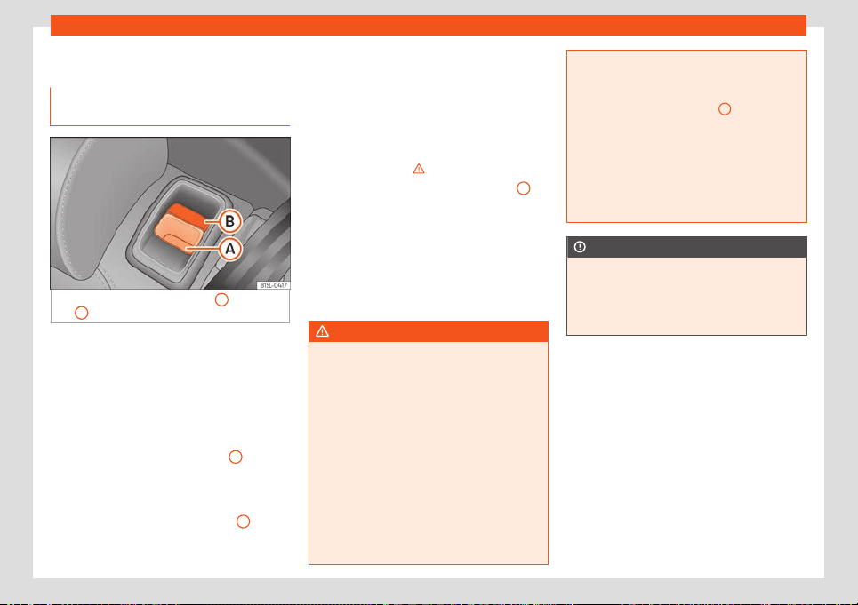
Operation
Seat functions
F
ol
ding do
wn and raising the rear
seat backrest
Fig. 93 Rear seat: unlock button
A
; red mark-
ing
B
.
The rear seat backrest can be folded forward
t
o e
xt
end the luggage compartment.
Folding the rear seat backrest forwards
●
Push the head restraint down as far as it will
go or remove it if necessary and store it in a
safe place.
●
Pull the unlock switch
›››
Fig. 93
A
for-
w
ar
ds whil
st simultaneously lifting the rear
seat backrest.
●
The rear seat backrest is not engaged
when the red marking of the button
B
is visi-
bl
e
.
●
If the r
ear seat backrest is folded, people
(including children) are not permitted to trav-
el in the rear folded seats.
Folding up the rear seat backrest
●
Lift back the backrest of the rear seat and
push it firmly into the lock until it clicks se-
curely into place
›››
.
●
The red marking on the unlock button
B
must not be seen.
●
Make sure that the backrest of the rear seat
is secur
ely l
ock
ed in position so that the seat
belts can provide proper protection in the
rear seats.
●
If necessary, reinstall and readjust the head
restraints.
WARNING
Folding and lifting the backrests of the rear
seats carelessly without paying att
ention
could cause serious injury.
●
Never fold or lift the seats while driving.
●
Do no trap or damage seat belts when
raising the seat backrest.
●
Keep hands, fingers, feet and other limbs
away from the range of the rear seat
backrests when folding and lifting them.
●
All seat backrests must engage correctly
for the seat belts on the rear seats to work
properly. When the backrest of an occu-
pied seat is not correctly locked in place,
the passenger can be thrust forward with
the rear seat backrest in case of sudden
braking, sudden manoeuvres or an acci-
dent.
●
A r
ed signal on the button
B
warns that
the backrest is not engaged. Alw
ays check
to make sure that the red mark is not visible
when the backrest of the rear seat is in the
upright position.
●
No seat must be occupied if the backrest
of the rear seat is folded or not correctly
engaged.
CAUTION
Before folding the rear seat backrest, ad-
just the front seats so that neither the head
restr
aint or backrest hit them when folded.
If necessary, remove the head restraints
and store them safely.
88
Transport and practical equipment
Transport and practical
equipment
St
oring ob
jects
P
ositioning the luggage and cargo
It is possible to transport cargo and luggage
in the vehicle and on the r
oof
›››
page 92.
When doing so, please consider all legal pro-
visions.
Placing luggage inside the vehicle safely
●
Distribute the load in the vehicle as evenly
as possible.
●
Al
ways place equipment and heavy ob-
jects in the boot
›››
.
●
Position heavy items in the boot as far for-
w
ar
d as possibl
e.
●
Take into account the maximum authorised
weight per axle, as well as the maximum au-
thorised weight of the vehicle
›››
page 211.
●
Secure the objects to the fastening rings of
the boot using appropriate chains or belts
›››
page 91.
●
Also place small objects safely.
●
Adapt tyre pressure to the load. Take into
account the pressure sticker of the tyres
›››
page 188.
●
In vehicles equipped with tyre control sys-
tem, adjust to the new load status if necessa-
ry
›››
page 192.
WARNING
Loose or unsecured objects can cause seri-
ous injury in case of sudden manoeuvring
or braking or in case of an accident. Par
tic-
ularly if the airbag hits them when deploy-
ing and they are thrown across the inside of
the vehicle. Please observe the following
rules to minimise the risk of injury:
●
Place all objects inside the vehicle safe-
ly.
●
Secure all objects, little and large.
●
Place the objects in the cabin in such a
way that they can never reach the airbag
deployment areas while the vehicle is in
motion.
●
Keep the storage compartments closed
at all times while the vehicle is in motion.
●
Place the objects in such a way that they
never force any occupant of the vehicle to
sit in an incorrect position.
●
When transporting objects that take up a
seat, never let anyone use that seat.
●
Never leave hard, sharp or heavy objects
loose in open storage compartment of the
vehicle, on the cover behind the rear seat
or on the instrument panel.
●
Remove all hard, sharp or heavy objects
from the fabrics and bags inside the cabin
and store them safely.
WARNING
The transport of heavy object changes ve-
hicle handling and increases br
aking dis-
tance. Heavy objects that are not properly
placed or secured may cause loss of con-
trol of the vehicle and thus severe injuries.
●
Never put too much load in the vehicle.
Both the carrying capacity as well as the
distribution of the load in the vehicle have
effects on the driving behaviour and brak-
ing ability.
●
When transporting heavy objects, the
driving behaviour of the vehicle varies due
to the displacement of the centre of gravi-
ty.
●
Always distribute the load in the vehicle
as evenly and horizontally as possible.
●
Always place heavy objects in the boot
before the rear axle and as far away from it
as possible.
●
Objects in the luggage compartment
that are unsecured could move suddenly
and modify the handling of the vehicle.
●
Adapt your speed and driving style at all
times to suit visibility, weather, road and
traffic conditions.
●
Accelerate with particular care and cau-
tion.
●
Avoid sudden braking and manoeuvres.
●
Brake earlier than usual.
»
89
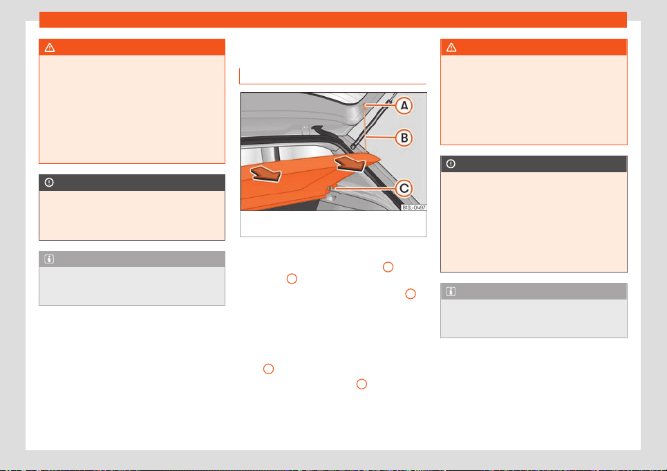
Operation
WARNING
●
Never l
eave your vehicle unattended, es-
pecially when the rear lid is open. Children
could climb into the luggage compartment,
closing the door behind them; they will be
trapped and run the risk of death.
●
Close and lock all the doors and the rear
lid when you leave the vehicle. Before you
lock the vehicle, make sure that there are
no adults or children in the vehicle.
CAUTION
Electrical wires or, depending on the fea-
tures, the ant
enna embedded into the rear
windows could be damaged, even irrepara-
bly, if they are in contact with objects.
Note
Straps for securing the load to the fasten-
ing rings are commercially av
ailable from
accessory shops.
Luggage compartment
L
uggage compar
tment shelf
Fig. 94 In the luggage compartment: remov-
ing and fitting the shelf
.
Removing
●
Detach the cord loops
›
›
›
Fig. 94
B
from
their hooks
A
.
●
Unclip the shelf from the side supports
C
by pulling it up and removing the shelf.
Fitting
●
Insert the shelf horizontally to make the
“horseshoe” coincide with the axis of sup-
ports
C
and press down until it engages.
●
Attach the securing straps
B
onto the rear
lid.
WARNING
Animals, loose or unsecured or objects car-
ried on the rear shelf can cause serious in-
jury in case of sudden manoeuvring or
braking or in case of an accident.
●
Do not l
eave hard, sharp or heavy ob-
jects or in bags on the rear shelf.
●
Never transport animals on the rear shelf.
CAUTION
●
Before cl
osing the rear lid, ensure that
the rear shelf is correctly fitted.
●
An overloaded luggage compartment
could mean that the rear shelf is not cor-
rectly seated and it may be bent or dam-
aged.
●
If the luggage compartment is overloa-
ded, remove the tray.
Note
Ensure that, when placing items of clothing
on the luggage compartment cov
er, rear
visibility is not reduced.
90
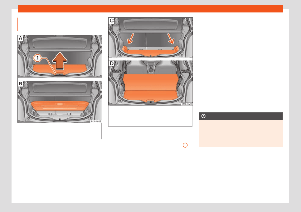
Transport and practical equipment
Variable luggage compartment
fl
oor
Fig. 95 Variable luggage compartment floor:
R
aise the adjust
abl
e floor; adjustable
floor raised.
Fig. 96 Variable luggage compartment floor:
Enl
ar
ge the luggage compartment do
wn-
wards; enlarge the luggage compartment
forward.
Raise and lower the luggage compart-
ment fl
oor
●
T
o
raise the floor, lift lever
›››
Fig. 95
1
in
the dir
ection of the arr
o
w and pull on the floor
fully upwards
›››
Fig. 95 .
●
To lower it, guide the floor downward.
Extend the luggage compartment down-
ward
●
Lift the luggage compartment floor and
push it down on the guide
›››
Fig. 96 (ar-
rows).
●
Place the variable floor over the floor lining.
●
If necessary, fold the backrest of the rear
seat forward
›››
page 88.
Extending the luggage compartment for-
ward
●
Disassemble the luggage compartment
tray
›››
page 90.
●
Remove the rear head restraints.
●
Fold the backrest of the rear seat forward
›››
page 88.
●
If necessary, place the luggage compart-
ment floor at a lower position
›››
Fig. 96 .
The luggage compartment is enlarged for-
ward
›››
Fig. 96 .
CAUTION
Do not let the luggage compartment floor
fall when closing it. Al
ways carefully guide
it downward in a controlled manner. Other-
wise, the lining and the floor of the luggage
compartment could be damaged.
Fastening rings*
There are fastening rings on the front and
r
ear of the boot t
o secur
e loose objects and
luggage with fastening belts and cords.
»
91
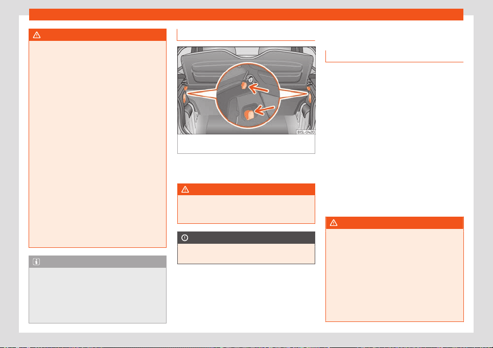
Operation
WARNING
If unsuitable or damaged belts or retaining
straps are used, they coul
d break in the
event of braking or an accident. Objects
could then be launched across the passen-
ger compartment and cause serious or fa-
tal injuries.
●
Always use belts or straps that are suita-
ble and in good condition.
●
Tighten the belts and straps in a cross
layout over the load placed on the boot
floor and secure them to the fastening rings
safely.
●
Never exceed the maximum tensile load
of the fastening rings when securing ob-
jects.
●
Make sure that, particularly for flat ob-
jects, the upper edge of the load is higher
than the fastening rings.
●
Depending on the features, take into ac-
count the instruction panels on the boot on
how to place the load.
●
Never secure a child seat to the fastening
rings.
Note
●
The maximum tensile l
oad that the fas-
tening rings can support is approx. 3.5 kN.
●
Belts, straps and securing systems for the
appropriate load can be obtained from
specialised dealerships. SEAT recom-
mends visiting a SEAT dealership for this.
Bag hooks
Fig. 97
In the luggage compartment: bag
hooks.
There may be hooks in the upper left and
right part of the luggage compartment.
WARNING
Never use these hooks to secure objects. In
case of sudden braking or an accident,
they could rupt
ure.
CAUTION
The hooks can support a maximum of 2.5 kg
each.
Roof carrier*
Intr
oduction
The vehicle roof has been designed to opti-
mise aerodynamics. For this r
eason, cross
bars or conventional roof carrier systems
cannot be secured to the roof water drains.
As the roof water drains are integrated in the
roof to reduce air resistance, only SEAT-ap-
proved cross bars and roof carrier systems
can be used.
Cases in which cross bars and the roof
carrier system should be disassembled.
●
When they are not used.
●
When the vehicle is washed in a car wash.
●
When the vehicle height exceeds the maxi-
mum height, for ex
ample, in some garages.
WARNING
●
Always secur
e the load properly using
belts or retaining straps that are suitable
and in a good condition.
●
Bulky, heavy, long or flat loads have a
negative effect on aerodynamics, the cen-
tre of gravity and driving performance.
●
Avoid sudden braking and manoeuvres.
●
Adapt your speed and driving style at all
times to suit visibility, weather, road and
traffic conditions.
92
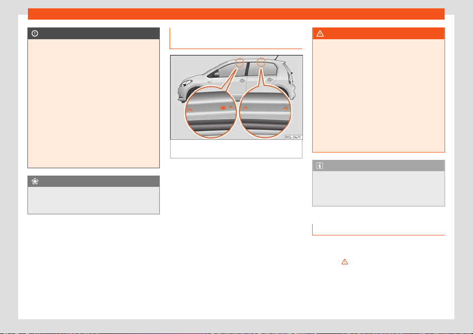
Transport and practical equipment
CAUTION
●
Remov
e the cross bars and the roof carri-
er system before entering a car wash.
●
Vehicle height is increased by the instal-
lation of cross bars or a roof carrier system
and the load secured on them. For this pur-
pose, check that your vehicle's height does
not surpass the headspace limit, for exam-
ple, for underpasses or for entering garage
doors.
●
Any cross bars, roof carrier systems or
loads secured to them must not interfere
with the roof aerial or block the path of the
rear lid.
●
On opening the rear lid make sure that it
does not knock into the roof load.
For the sake of the environment
When crossbars and a roof carrier system
are install
ed, the increased air resistance
means that the vehicle uses more energy.
Securing the crossbars and the
r
oof carrier syst
em
Fig. 98
Attachment points for the roof railings
f
or the r
oof carrier syst
em.
The crossbars are the basis of a series of
special r
oof carrier syst
ems. F
or safety rea-
sons, special fixtures must be used to safely
transport luggage, bicycles, skis, surf boards
or boats on the roof. Suitable accessories
can be acquired at SEAT dealerships.
Always secure the crossbars and the roof
carrier system properly. Always take the as-
sembly instructions that come with the cross-
bars and the roof carrier system in question
into account.
The holes or marks indicating the fitting
points for base supports are in the lower half
of the roof struts and can only be seen with
the door open
›››
Fig. 98.
WARNING
Incorrect attachment and use of the cross-
bars and the roof carrier system may cause
the whol
e system to detach from the roof
and cause an accident and injuries.
●
Always take the manufacturer assembly
instructions into account.
●
Check threaded joints and attachments
travelling and if necessary tighten them af-
ter you have travelled a short distance.
When making long trips, check the threa-
ded joints whenever you stop for a rest.
●
Do not modify or repair the crossbars or
roof carrier system.
Note
Always read the assembly instructions that
come with the crossbars and the roof carri-
er syst
em carefully and keep them in the
vehicle.
Loading the roof carrier system
The load can only be secured if the crossbars
and the r
oof carrier syst
em ar
e properly in-
stalled
›››
.
Maximum authorised car
go on the r
oof
The maximum permissibl
e roof load is 50 kg.
This figure comes from the combined weight
»
93
Operation
of the roof carrier, the cross bars and the load
itself on the r
oof
›
›
›
.
Al
w
ays check the w
eight of the roof carrier
system, the cross bars and the weight of the
load to be transported and weigh them if
necessary. Never exceed the maximum au-
thorised roof load.
If you are using cross bars and a roof carrier
with a lower weight rating, you will not be
able to carry the maximum authorised roof
load. In this case, do not exceed the maxi-
mum weight limit for the roof carrier which is
listed in the fitting instructions.
Distributing a load
Distribute loads uniformly and secure them
correctly
›››
.
Check att
achments
Once the cr
oss bars and r
oof carrier system
have been installed, check the bolted con-
nections and attachments after a short jour-
ney and subsequently with a certain frequen-
cy.
WARNING
●
Never e
xceed the maximum authorised
load on the roof and on the axles or the ve-
hicle's maximum authorised weight.
●
Never exceed the load capacity of the
cross bars and the roof carrier system,
even if the maximum authorised roof load
has not been reached.
●
Secure heavy it
ems as far forward as
possible and distribute the vehicle load
uniformly.
WARNING
If the load is loose or not secured, it could
f
all from the r
oof carrier system or cause
accidents and injuries.
●
Always use belts or retaining straps that
are suitable and in a good condition.
Storage compartment
Intr
oduction
Use the storage compartments only for small
or light it
ems.
WARNING
Objects in the driver's footwell could diffi-
cult the use of the pedals. This may cause
loss of contr
ol of the vehicle and increases
the risk of severe injuries.
●
Make sure that nothing prevents you from
using the pedals at any time.
●
Always secure the mat in the footwell.
●
Never place other mats or other type of
covers on the factory-fitted mat.
●
Ensure that no objects can f
all into the
driver's footwell while the vehicle is in mo-
tion.
●
When the vehicle is stationary, remove
the objects in the footwell.
WARNING
If you leave lighters inside the vehicle, they
might be damaged or lit inadv
ert
ently. This
could lead to severe burns and damage to
the vehicle.
●
Before moving a seat, make sure there
are no lighters in the moving part area of
the vehicle.
●
Before closing a storage compartment,
make sure there are no lighters in the clos-
ing area.
●
Never leave a lighter inside a storage
compartment or any other surface of the
vehicle as it could ignite due to the high
temperatures on such surfaces, particular-
ly during the summer.
CAUTION
●
Do not store heat
- or cold-sensitive ob-
jects, food or medicines in the cabin. Heat
and cold could damage them or render
them useless.
●
Objects made from transparent materi-
als left inside the vehicle, such as glasses,
magnifying glasses or transparent suction
94
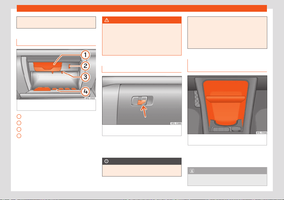
Transport and practical equipment
pads stuck to the windows can concentrate
sunlight and damage the vehicle
.
Glove compartment
Fig. 99
On the front passenger side: glove
compartment open
Glasses case
Support f
or a not
epad
P
en holder
Coin holder
Opening and closing the glove compart-
ment
●
Opening: Pull on the handle and open the
glove compartment.
●
Closing: Press the glove compartment up-
wards.
1
2
3
4
WARNING
If the glove compartment is left open, the
risk of causing sever
e injuries in the event
of an accident, sudden braking or manoeu-
vring increases.
●
Always keep the glove compartment
closed while the vehicle is in motion.
Bag support*
Fig. 100 Storage compartment on the pas-
senger side: f
ol
ding hook
.
On the glove compartment lever there is a
f
ol
ding hook
›
››
Fig. 100 for hanging small
pieces of luggage, such as bags, etc.
CAUTION
●
The maximum weight for the hook is 1.5
k
g.
●
With the hook folded f
orward, this auto-
matically folds away when opening the
glove compartment.
●
We recommend you remove any pieces
of luggage hanging from the hook before
opening the glove compartment cover.
Compartment in the front centre
console.
Fig. 101
In the front part of the centre console:
st
or
age compartment.
The storage compartment
›
›
›
Fig. 101 can be
used to store drinks
›››
page 97, for the ash-
tray*, or for storing small objects.
Note
A 12 volt electrical socket
›››
page 97 can
be found in the storage compartment.
95

Operation
Other object holders
Fig. 102
On the centre pillars: coat hooks.
You will find more object holders, compart-
ments and supports in other parts of the v
ehi-
cl
e:
●
Hooks f
or clothing on the centre pillars
›››
Fig. 102 (arrow).
●
On the trims of the front doors.
●
Rear shelf for light items of clothing*.
●
Bag hook in the luggage compartment
›››
page 92.
Drink holder
Introduction
Bottle holder
The storage compartments of the driv
er and
passenger doors contain a bottle holder.
WARNING
Incorrect use of the bottle holders may
cause injuries.
●
Never put hot drinks in the drink holders.
In the event of sudden br
aking or an acci-
dent while driving, hot beverages in the
bottle holders might spill and cause burns.
●
Ensure that no bottles or other objects
are dropped in the driver footwell while
driving, as they could get under the pedals
and obstruct their working.
●
Never place glasses, food or other heavy
objects drink holders. These heavy objects
may be thrown across the cabin in the
event of an accident and cause serious in-
juries.
WARNING
Closed bottles may explode inside the ve-
hicle due to col
d or heat.
●
Never leave closed bottles in the vehicle
if the temperature inside is very high or very
low.
CAUTION
Do not leave open cans in the drink holders
when the vehicle is in motion. If the drink is
spill
ed (e.g. due to sudden braking) it may
damage the vehicle and its electrical sys-
tem.
Note
The inside elements of the drink holders
can be extract
ed for cleaning.
96
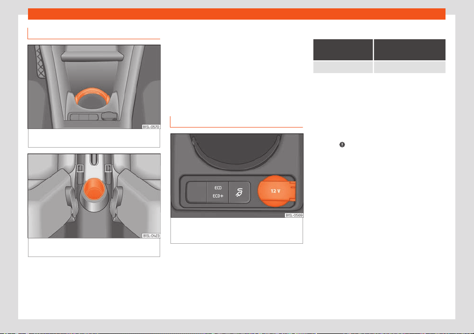
Transport and practical equipment
Drink holder of the centre console
Fig. 103
In the front part of the centre console:
drinks hol
der
.
Fig. 104
In the rear part of the centre console:
drinks hol
der
.
There are drink holders in the front and rear
parts of the centr
e consol
e
.
Securing the drink container in the front
drink holder
Fold the drink holder
›››
Fig. 103 forward.
Place the drink container in the drink holder
so that it is securely surrounded.
Power sockets
Power outlet and USB socket*
Fig. 105 Front centre console: 12-volt power
outl
et on the st
or
age compartment and USB in-
terface.
Electrical equipment can be connected to
the sock
et in the v
ehicl
e.
All connected appliances should be in per-
fect working order without any faults.
Maximum power consumption
Power socket
Maximum power con-
sumption
12 Volts 120 Watts
The maximum capacity of the socket must
not be exceeded. The po
wer consumption is
indicated on the rating plate of each appli-
ance.
Where 2 or more appliances are connected
at the same time, the total rating of all the
connected devices must never exceed 190
Watts
›››
.
12 v
olt po
w
er socket
The 12 volt socket is located in the storage
compartment at the front of the centre con-
sole
›››
Fig. 105 and only works when the ig-
nition is switched on.
With the ignition switched on, the drive sys-
tem stopped and the electrical appliances
switched on, the vehicle's 12-volt battery is
discharged. Therefore, electrical devices
connected to the socket should only be used
when the drive system is operating.
To prevent voltage fluctuations from causing
damage, turn off the electrical device con-
nected to the 12-volt socket before connect-
ing and disconnecting the ignition, as well as
before starting the drive system.
»
97

Operation
WARNING
Improper use of the socket or electrical de-
vices could lead t
o a fire and cause serious
injuries.
●
Never leave children unsupervised in the
vehicle. The socket and equipment con-
nected to it can be used when the ignition is
switched on.
●
Should a connected electrical device
overheat, switch it off and unplug it imme-
diately.
CAUTION
●
Take int
o account the operating instruc-
tions of the devices to be connected!
●
Never exceed the maximum power rating
as this could damage the vehicle's general
electrical system.
●
To avoid damaging the vehicle’s electri-
cal system, never connect accessories
supplying power such as solar panels or
battery chargers for charging the 12-volt
battery to the 12-volt power socket.
●
Only use accessories with approved
electromagnetic compatibility according
to current regulations.
●
To avoid damage due to voltage fluctua-
tions, switch off all devices connected to
the 12 V power sockets before switching the
ignition on or off and before starting the
drive system.
●
Never connect an appliance t
o the 12 volt
power socket that consumes more than the
power indicated in watts. Exceeding the
maximum power absorption could damage
the vehicle's electrical system.
Note
●
Unshiel
ded equipment can cause inter
-
ference on the radio equipment and the ve-
hicle's electrical system.
●
Interference can occur on the radio's AM
waveband if electrical appliances are used
near the aerial.
Smartphone support
P
or
t
able smartphone holder
Fig. 106
Assembling the universal support and
the hol
ding arm.
Fig. 107
In the centre console: close the com-
partment wher
e the inf
ot
ainment system is
housed.
Removing the smartphone
●
Grip the smartphone firmly with one hand.
●
Press the release button
›
›
›
Fig. 107
5
until
the t
op arm of the univ
ersal hol
der disengag-
es.
●
Remove the smart phone and, as the case
may be, unplug any cables.
Inserting a smart phone
●
If necessary, install the smartphone hous-
ing
›››
.
●
Connect the smartphone.
●
Place the smartphone on the bottom
mountings. T
o adjust the bott
om mountings,
pr
ess button
›››
Fig. 107
4
.
98
Transport and practical equipment
●
Pr
ess the t
op arm of the univ
ersal holder
until the smartphone is securely held in place.
Disassembling the housing
●
If necessary, remove the smartphone.
●
Grip the universal holder
›››
Fig. 106
3
and
pr
ess the r
el
ease button
›››
Fig. 106
4
.
●
Push the universal holder to the right (anti-
cl
ockwise) and r
emo
ve it.
●
Grip the holder arm and
›››
Fig. 107
1
and
pr
ess the r
el
ease button
›››
Fig. 107
4
in the
dir
ection of the arr
o
w.
●
Remove the holder from the instrument
panel upwards.
Install the housing
●
Insert the universal holder
›››
Fig. 106
3
in-
t
o the sl
ots
2
on the holder
1
.
●
Move the universal holder to the side in the
l
ocking dir
ection
4
until it engages audi-
bly
›
›
›
.
●
Place the holder arm
›
›
›
Fig. 107
1
in the
anchoring pl
at
e
›
››
Fig. 107
3
from above
and pr
ess do
wn on it until you hear it en-
gage
›
››
.
WARNING
If a smartphone is not secured or is incor-
rectly secured in the v
ehicle, it could be
flung though the interior during a sudden
driving or braking manoeuvre or in the
event of an accident, and could cause inju-
ries.
●
The infotainment system holder must be
properly secured in the corr
esponding gap
in the instrument panel.
●
The infotainment system must always be
properly secured in its holder or stored
safely in the vehicle.
CAUTION
If tilt and angle of visibility are not properly
adjust
ed the smart phone coul
d be dam-
aged.
●
When adjusting the smartphone, move it
with care and never beyond its limits.
CAUTION
At very high or very low temperatures the
smartphone might not operat
e properly, or
the actual device could get damaged.
●
Take your smart phone with you when
you get out of the vehicle to protect it from
very high or very low temperatures, and
from intense solar radiation.
CAUTION
Humidity can damage the electrical con-
tacts for the smar
tphone on the instrument
panel.
●
Do not wet the smartphone’s housing
when cleaning it. Use only a dry cloth.
Note
SEAT recommends that you always take
your smart phone with you when you get
out of the vehicl
e to avoid possible thefts.
99
Operation
Air conditioning
Heating, v
entil
ation and
cooling
Intr
oduction
The Climatronic cool
s and dehumidifies the
air. Its optimum performance is achieved with
the windows closed.
To switch a specific function on, press the ap-
propriate button. Press the button again to
switch off the function.
The LED on each control lights up to indicate
that the respective function of a control has
been switched on.
Dust and pollen filter
The dust and pollen filter with its activated
charcoal cartridge serves as a barrier
against impurities in the air taken into the ve-
hicle interior.
The dust and pollen filter must be changed
regularly so that air conditioner performance
is not adversely affected.
If the filter loses efficiency prematurely due to
use in areas with very high levels of air pollu-
tion, the filter must be changed more fre-
quently than stated in the Service Schedule.
WARNING
Reduced visibility through the windows in-
creases the risk of serious accidents.
●
Alw
ays ensure that all windows are free
of ice and snow, and that they are not fog-
ged, so as to maintain good visibility of ev-
erything outside.
●
Only drive when you have good visibility.
●
Always ensure that you use the air condi-
tioner and heated rear window to maintain
good visibility.
●
Never leave the air recirculation on for a
long period of time. If the cooling system is
switched off and air recirculation mode
switched on, the windows can mist over
very quickly, considerably limiting visibility.
●
Switch air recirculation mode off when it
is not required.
WARNING
Stuffy or used air will increase fatigue and
reduce driver concentr
ation possibly re-
sulting in a serious accident.
●
Never leave the fresh air fan turned off or
use the air recirculation for long periods of
time; the air in the vehicle interior will not
be refreshed.
CAUTION
●
To repl
ace the pollen filter, always visit a
service centre.
●
Switch the air conditioner off if you think
it may be br
oken. This will avoid additional
damage. Have the air conditioner checked
by a specialised workshop.
●
Repairs to the air conditioner require spe-
cialist knowledge and special tools. SEAT
recommends visiting a SEAT Official Serv-
ice.
Note
●
When the cooling syst
em is turned off
, air
coming from the outside will not be dried.
To prevent fogging of the windows, SEAT
recommends leaving the cooling system
(compressor) turned on. To do this, press
the
button. The button lamp should
light up.
●
The maximum heat output requir
ed to de-
frost windows as quickly as possible is only
available when the engine has reached its
normal running temperature.
●
Keep the air intake slots in front of the
windscreen free of snow, ice and leaves to
ensure heating and cooling are not im-
paired, and to prevent the windows from
misting over.
●
The air from the vents flows through the
vehicle interior and is extracted by slots in
the luggage compartment designed for this
purpose. Therefore, you should avoid ob-
structing these slots with any kind of ob-
ject.
100
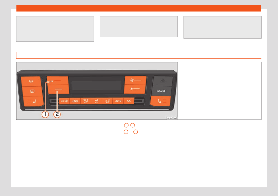
Air conditioning
●
Do not smoke while air r
ecirculation
mode is on, as smoke drawn into the air
conditioning system leaves residue on the
evaporator, producing a permanent un-
pleasant odour.
●
It is advisable to t
urn on the air condition-
ing at least once a month, to lubricate the
system gaskets and prevent leaks. If a de-
crease in the cooling capacity is detected,
a Technical Service should be consulted to
check the system.
●
When the engine is under extr
eme strain,
switch off the compressor for a moment.
Climatronic* controls
Fig. 108 In the centre console: Climatronic con-
trols.
Automatic mode
Aut
omatic adjustment of t
emperature, fan,
and air distribution. Automatic mode is disa-
bled when the ventilation is modified manual-
ly.
Cooling mode
Press the button to switch on or off the cool-
ing system.
Temperature
1
/
2
Press buttons
1
or
2
. The selected temper-
at
ur
e is sho
wn on the display of the climate
control panel.
Blower
The power of the fan is automatically adjus-
ted.
Press the buttons to manually adjust the fan.
Air distribution / /
The airflow adjusts automatically for comfort.
It can also be manually distributed to the de-
sired zone by pressing the corresponding
button:
The airflow is directed towards the chest
The airflow is directed towards the foot-
well.
The airflow is directed at the windscreen.
»
101
Operation
Defrost/demist function
The air dr
awn in fr
om outside the v
ehicle is di-
rected at the windscreen and air recirculation
is automatically switched off. To defrost the
windscreen more quickly, the air is dehumidi-
fied at temperatures over approximately
+3°C (+38°F) and the fan runs at maximum
output.
Windscreen heating
Press the button to connect and disconnect
the windscreen heating with the engine run-
ning.
Heated rear window
This only works when the engine is running
and switches off automatically after a maxi-
mum of 10 minutes.
It should be switched off as soon as the glass
is demisted. Lower electricity consumption
has a positive effect on energy consumption.
To avoid possible damage to the battery, an
automatic temporary disconnection of this
function is possible, coming back on when
normal operating conditions are re-establish-
ed.
Air recirculation
›››
page 103
Seat heating
›››
page 103
Switching off
Press the lower button several times .
Climate control usage instructions
The interior cooling system only works when
the engine is running and fan is swit
ched on.
Economic use of the air conditioning
When the air conditioning is switched on, the
compressor consumes engine power and has
an influence on energy consumption.
The air conditioner operates most effectively
with the windows closed. However, if the pas-
senger compartment has become excessive-
ly hot due to being exposed to the sun, it will
cool down more quickly by opening the win-
dows for a moment.
The cooling system cannot be activated
If the air conditioning system cannot be
switched on, this may be caused by the fol-
lowing:
●
The engine is not running.
●
The fan is switched off.
●
The air conditioner fuse has blown.
●
The outside temperat
ure is lower than ap-
proximately +3°C (+38°F).
●
The air conditioner compressor has been
temporarily switched off because the engine
coolant temperature is too high.
●
Another fault in the vehicle. Have the air
conditioner checked by a specialised work-
shop.
Special characteristics
If the humidity and temperature outside the
vehicle are high, condensation can drip off
the evaporator in the cooling system and
form a pool underneath the vehicle. This is
normal and does not indicate a leak!
Note
After starting the engine, any residual hu-
midity in the air conditioner could mist o
ver
the windscreen. Switch on the defrost func-
tion as soon as possible to clear the wind-
screen of condensation.
Air vents
To ensure proper heating, cooling and venti-
l
ation in the v
ehicl
e interior, the air vents must
remain open.
●
With the fins of the diffusers you can open
and close the diffusers, as well as adjust the
direction in which you want the air to come
102
Air conditioning
out. To get the best possible air flow towards
the windo
ws, open the corr
esponding diffuser
and t
urn it to the de-icing/demisting position,
where it will lock.
There are other additional, non-adjustable air
vents in the instrument panel, in the footwells
and in the rear area of the passenger com-
partment.
Note
Food, medicine and other heat or cold sen-
sitive objects shoul
d never be placed in
front of the air outlets as they may be dam-
aged or made unsuitable for use by the air.
Air recirculation
Air recirculation mode prevents the ambient
air fr
om ent
ering the int
erior.
When the outside temperature is very high,
selecting manual air recirculation mode for a
short period refreshes the vehicle interior
more quickly.
For safety reasons, air recirculation mode is
switched off when the button is pressed
or the air distributor is turned to .
Switching the manual air recirculation
mode on and off
●
Press the button to connect or discon-
nect manual air recirculation.
WARNING
Observe the safety warnings
›››
in Intro-
duction on page 100.
●
If the cooling system is switched off and
air recircul
ation mode switched on, the
windows can mist over very quickly, con-
siderably limiting visibility.
●
Switch air recirculation mode off when it
is not required.
CAUTION
Do not smoke when air recirculation is
switched on in v
ehicles with an air condi-
tioner. The smoke taken in could lie on the
cooling system vaporiser and on the acti-
vated charcoal cartridge of the dust and
pollen filter, leading to a permanently un-
pleasant smell.
Note
When reversing, and while the windscreen
wipers are running, air recir
culation is acti-
vated to prevent exhaust gases or unpleas-
ant odours from entering the passenger
compartment.
Note
If the temperature regulator is turned to the
coldest setting (blue point), the air recir
cu-
lation function and the button are auto-
matically activated.
●
If the function is not deactivated by
pressing the button, it will deactivate after
approximately 20 minutes.
Seat heating*
With the engine on, the seat cushion and the
seat backr
est can be heat
ed el
ectrically.
Control seat heating
●
Press buttons or on the control panel
to turn on the seat heating as high as possi-
ble.
●
Press buttons o repeatedly to adjust it
to the required level.
●
To turn off the seat heating, press button
or repeatedly until no LEDs are lit.
When the seat heating is at the maximum lev-
el, after approx. 15 minutes it is automatically
adjusted to the first level.
Cases in which the heat seating should
not be switched on
Do not switch the seat heating on if any of the
following conditions are met:
»
103
Operation
●
The seat is not occupied.
●
The seat has a cover.
●
A child seat has been installed on the seat.
●
The seat cushion is wet or damp.
●
The outdoor or indoor temperature is great-
er than +25°C (7
7°F).
WARNING
People who cannot perceive pain or tem-
peratur
e because of medications, paralysis
or chronic diseases (e.g. diabetes) or have
a limited perception of these, may suffer
burns to the back, buttocks or legs when
using seat heating.
●
People with limited pain and temperature
thresholds must never use seat heating.
●
If an abnormality in the device's temper-
ature control is detected, have it checked
by a specialist workshop.
WARNING
If the fabric of the cushion is wet, this can
adversely affect the oper
ation of the seat
heating, increasing the risk of burns.
●
Make sure the seat cushion is dry prior to
using the seat heater.
●
Do not sit on the seat with clothing that is
wet or damp.
●
Do not leave clothing that is wet or damp
on the seat.
●
Do not spill liquid on the seat.
CAUTION
●
To avoid damaging the heating el
ements
of the seat heaters, please do not kneel on
the seat or apply sharp pressure to a single
point on the seat cushion or backrest.
●
Liquids, sharps objects and insulating
materials (e.g. covers or child seats) can
damage the seat heating.
●
In the event of smells, switch off the seat
heating immediately and have it inspected
by a specialised workshop.
For the sake of the environment
The seat heating should remain on only
when needed. Otherwise, it is unnecessary
energy consumption.
Stationary air conditioning
Intr
oduction
With the stationary air conditioning you can
cool, v
entil
at
e and heat the passenger com-
partment while the vehicle is parked. In win-
ter, you can also demist the windscreen and
leave it free of ice and snow (if the layer is
thin). The stationary air conditioning receives
the necessary energy from the vehicle’s high-
voltage battery or from the electrical network
through a power socket.
With the ignition off, you can manually con-
nect and disconnect the stationary air condi-
tioning with the corresponding application in-
stalled on a mobile phone. On the Internet
you can check out information about the ap-
plication, its availability and the necessary
requirements for its use, as well as on com-
patible terminals.
CAUTION
Never place food, medicines or other tem-
peratur
e-sensitive objects close to the air
vents. Food, medicines and other objects
sensitive to heat or cold may be damaged
or made unsuitable for use by the air com-
ing from the vents.
Note
If the stationary air conditioning is used
without the charging cable plugged in,
po
wer is consumed from the high-voltage
battery. At extreme temperatures, it is pos-
sible that the heating or cooling power of
the stationary air conditioning is insuffi-
cient to reach the set temperature.
Managing the stationary air condi-
tioning
The stationary air conditioning can be
s
wit
ched on and off manually (heating, v
enti-
lation or immediate cooling) or by means of a
104

Air conditioning
few pre-programmed departure times. The
st
ationary air conditioning is managed
thr
ough an application inst
alled on a mobile
phone.
Managing the stationary air conditioning
●
Automatically by programming and acti-
vating a departure time.
●
Manually with the corresponding applica-
tion installed on a mobile phone and the igni-
tion off.
Managing the stationary air conditioning
●
Press the button on the air conditioning
control panel.
●
Automatically at the scheduled departure
time or after the programmed operating time
has elapsed.
●
Automatically when the charge level of the
high-voltage battery drops too low
›››
page 158.
●
Manually with the corresponding applica-
tion installed on a mobile phone.
Air conditioning operating time
The operating time may vary depending on
the type of control and the status of the high-
voltage battery (whether it is charging or
not).
In the event of manual control
●
Charging connector plugged in. 15 minutes
●
Charging connector not plugged in. 10 mi-
nutes
In the event of a scheduled departure time
●
Charging connector plugged in. 30 minutes
of pre-run time
●
Charging connector plugged in. 15 minutes
of post-run time
●
Charging connector not plugged in. 15 mi-
nutes of pre-run time
●
Charging connector not plugged in. 5 mi-
nutes of post-run time
Operation without the charging connector
plugged in
The operation of the stationary air condition-
ing must be activated with the mobile phone
if the charging connector is not plugged in.
This setting is memorised in the vehicle.
The stationary air conditioning will not start
even if it has been programmed if the option
that allows air conditioning without the
charging connector being plugged in has not
been activated.
When the charging connector is not plugged
in, the stationary air conditioning receives the
necessary electrical power from the high-
voltage battery.
Operation with the charging connector
plugged in
When the charging connector is not plugged
in, the stationary air conditioning receives the
necessary electrical power from the high-
voltage battery. The operating possibilities of
the stationary air conditioning depend on the
type of charging process:
●
Charging with alternating voltage (charg-
ing with AC): The vehicle can only be charg-
ed or heated. If a departure time has been
programmed, the high-voltage battery is
charged first and the passenger compart-
ment is then heated or cooled. The charging
process is prolonged if the stationary air con-
ditioning is manually connected with the cor-
responding application installed on the mo-
bile phone.
●
Charging with direct current (charging with
DC): The vehicle can only be heated/cooled
during the charging process. The charging
station may be disconnected as soon as the
high-voltage battery is fully charged. The
passenger compartment will only be heat-
ed/cooled if the air conditioning option with-
out external power is activated.
If a departure time has been programmed
through the corresponding application, the
vehicle will calculate the previous time that
the stationary air conditioning needs. It can
be a maximum of 30 minutes.
»
105

Operation
Programming a departure time
What is pr
ogr
ammed is the desir
ed tempera-
ture in the passenger compartment for the
planned departure time. Starting from the de-
sired temperature, the vehicle calculates the
time necessary to reach it and, therefore, the
time at which the stationary air conditioning
has to be connected. It is possible to sched-
ule up to three departure times.
Maximum cooling or heating power
The maximum cooling or heating power can
be adjusted by the corresponding applica-
tion installed on a mobile phone.
●
Maximum cooling power: set the tempera-
ture below +18 °C (+64 °F).
●
Maximum heating power: set the tempera-
ture above +28 °C (+82 °F).
When the maximum cooling or heating power
is set, the temperature is adjusted. Therefore,
depending on the outside temperature, the
opposite function may briefly turn on.
Thus, for example, if the stationary air condi-
tioning has been set to the maximum cooling
power, the heating may be switched on if the
outside temperature is too low. The red sil-
houette of a vehicle will be shown on the dis-
play while the function opposite to the adjus-
ted one is active.
So, if the stationary air conditioning has been
set to the maximum heating power, the cool-
ing system may be switched on if the outside
temperature is too high. The blue silhouette of
a vehicle will be shown on the display while
the function opposite to the adjusted one is
active.
Note
●
If the charge le
vel of the high-voltage
battery drops excessively, the stationary
air conditioning switches off automatically
or cannot be switched on.
●
Noises will be heard while the stationary
air conditioning is running.
●
The longer or the more often the station-
ary air conditioning is used without exter-
nal power, the more the high-voltage bat-
tery will be discharged.
106
Introduction
Infotainment System
Intr
oduction
Saf
et
y warnings
Safety warnings regarding the Info-
tainment system
Only operate the infotainment system and its
various functions when the traffic sit
uation
really permits this.
WARNING
●
Before st
arting the trip, you should famili-
arise yourself with the different infotain-
ment system functions.
●
High audio volume may represent a dan-
ger to you and to others. Hearing may be
impaired if the volume is too high, even for
short periods of time.
●
Changes to the Infotainment system set-
tings should be made when the car is stop-
ped, or by a passenger.
WARNING
Current traffic requires maximum attention
from public road users. Distr
acting the driv-
er in any way can lead to an accident and
cause injuries. Operating the Infotainment
system can distract your attention from the
traffic.
●
Alw
ays drive carefully and responsibly.
●
Select volume settings that allow you to
hear sounds from outside the vehicle at all
times (e.g. emergency services sirens and
horns).
WARNING
The volume level may suddenly change
when you s
witch audio sour
ce or connect a
new audio source.
●
Lower the basic volume before connect-
ing or switching audio sources.
WARNING
The driving recommendations and traffic
indications shown on the navigation system
may diff
er from the current traffic situation.
●
Traffic signs and traffic regulations have
priority over the recommendations and dis-
plays provided by the navigation system.
WARNING
Connecting, inserting or removing a data
medium while driving can distract your at
-
tention from the traffic and cause an acci-
dent.
WARNING
Place the connecting cables of external
equipment so that they do not interfer
e
with the driver’s mobility.
WARNING
External devices that are loose or not prop-
erly secured could mo
ve around the pas-
senger compartment during a sharp ma-
noeuvre or accident.
●
Avoid placing external devices on the
doors, windscreen, steering wheel, instru-
ment panel, the backs of the seats, on top
of or near the area marked “AIRBAG” or be-
tween these areas and the occupants.
They could cause serious injury in an acci-
dent, especially when the airbags inflate.
WARNING
The armrest* must always remain closed
during the journey as it could restrict the
driv
er’s movements.
CAUTION
The Infotainment system can be damaged
by the incorrect insertion of a dat
a storage
device or the insertion of an incompatible
data storage device.
●
When inserting a data storage device,
make sure it is correctly positioned.
»
107

Infotainment System
●
Applying force may irr
eparably damage
the memory card slot locking mechanism.
●
Only use compatible memory cards.
CAUTION
The vehicle loudspeakers may be dam-
aged if the v
olume is too high or the sound
is dist
orted.
Note
For the proper functioning of the Infotain-
ment system it is import
ant that the date
and time set in the vehicle are correct.
108
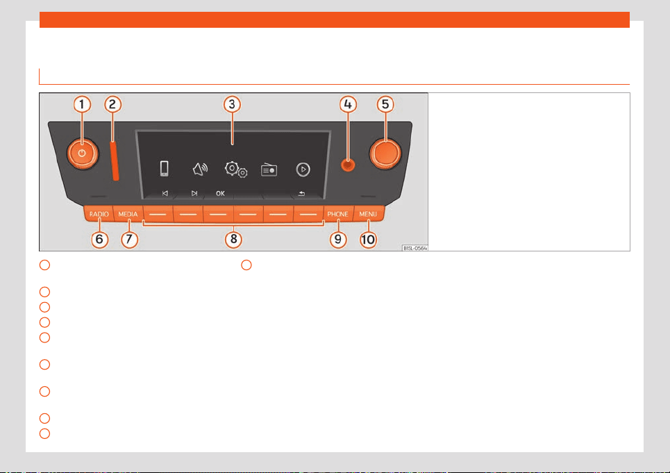
Introduction
Overview of the unit
Y
ou&Mii Col
our Connection
Fig. 109
Overview of the controls
Volume. Off and on
›
›
›
page 111,
›››
page 111
Slot for SD cards
›››
page 122
Screen
AUX-IN multimedia socket
›››
page 124
Settings button (search and selection)
›››
page 111
Radio mode (change of band frequency)
›››
page 115
Media mode (audio sources)
›››
page 120
Function buttons
›››
page 111
Telephone mode
›››
page 125
1
2
3
4
5
6
7
8
9
Selecting the main menu
›
›
›
page 110
»
10
109
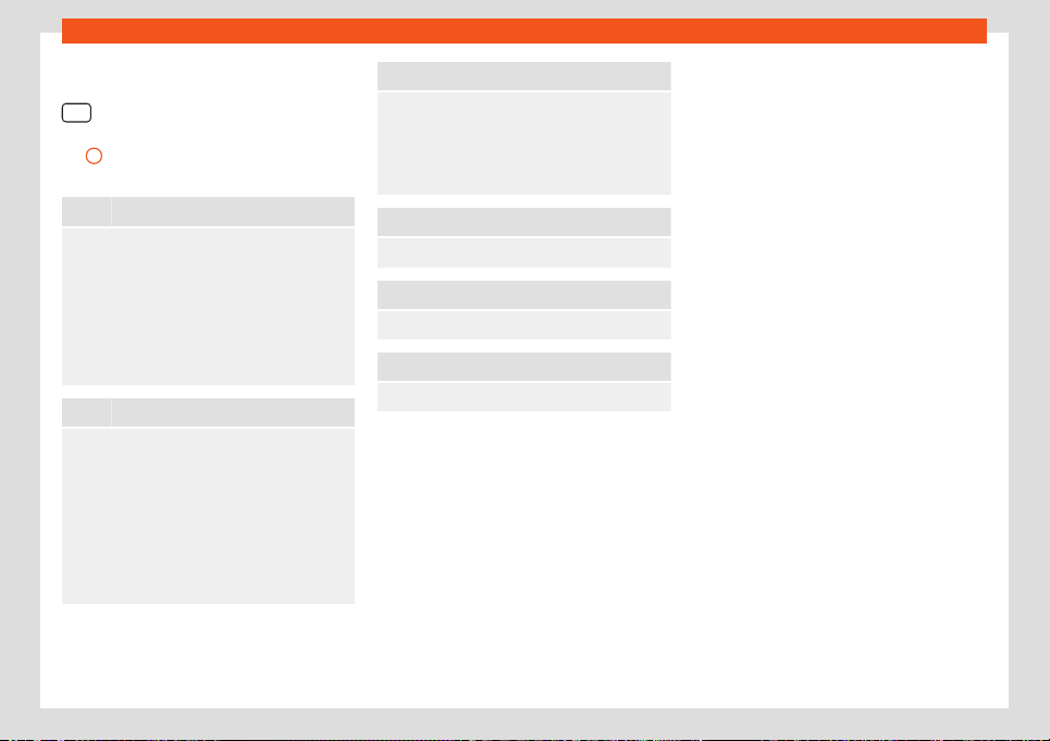
Infotainment System
Main menus
●
To access the main menu, press button
.
●
To select a function, rotate the setting But-
t
on
5
until it is highlighted and press the set
butt
on.
Radio
›››
page 115
RADIO main menu
›››
page 115
RDS
›››
page 115
TP function
›››
page 116
Changing frequency band
›››
page 117
Changing station
›››
page 117
Presetting stations
›››
page 118
Choosing memorised stations
›››
page 118
Digital radio mode
›››
page 118
Media
›››
page 120
Media sources and audio files
›››
page 120
Playback order
›››
page 121
Select a Media source
›››
page 121
SD card
›››
page 122
USB port
›››
page 123
Bluetooth
›››
page 123
AUX-IN jack
›››
page 124
Track information
›››
page 125
Changing the playback mode
›››
page 125
Telephone
›››
page 125
Connection and operation
›››
page 125
Functions of the phone
›››
page 126
Favourites
›››
page 127
Call by telephone
›››
page 127
Settings of a connected phone
›››
page 127
Drive Mii App*
›››
page 128
Connection and operation
›››
page 128
Sound
Sound and volume settings
›
››
page 112
Setup
System and function settings
›
››
page 112
110
Introduction
General instructions for use
Additional instructions
Depending on the vehicle, notifications of the
factory-fitt
ed driving assistance systems are
shown on the display. The notifications close
automatically when they are no longer use-
ful.
All notifications are only displayed after com-
pletely resetting the radio system.
Note
●
Pushing the buttons gently is enough to
use the equipment.
●
Due t
o country-specific legislation, cer-
tain functions may not be available when
the vehicle is travelling above a certain
speed.
●
Using a mobile telephone inside the vehi-
cle may cause noise in the speakers.
●
On some vehicles with ParkPilot, the vol-
ume of the active audio source is automati-
cally lowered when reverse gear is selec-
ted.
Rotary push buttons, equipment
and function butt
ons
Overview
●
Rotary push buttons.
●
Equipment buttons named (physical but-
tons).
●
Function butt
ons (virtual buttons).
Rotary push buttons
The left-hand rotary push button is known
as volume control or the on/off button.
The right-hand rotary push button is known
as the settings button.
Equipment buttons and function buttons
The named buttons of the equipment are
known as “equipment buttons” and are
shown with a button symbol inside a rectan-
gle, for instance, equipment button
.
Unnamed equipment butt
ons ar
e l
ocated be-
low the display. These equipment buttons are
known as “function buttons” as their purpose
depends on the active function mode.
The function assigned to a function button is
explained on the bottom of the display,
above the corresponding button.
Switching on and off
●
To manually switch the system on and off,
briefly press the rot
ary push button .
When the unit is switched on the system
starts up. The last active audio source will be
played with the set volume, as long as this
does not exceed the maximum, predefined
“switch-on” volume ( Volume
).
Depending on the equipment and country,
when switching off the engine or r
emoving
the key from the ignition, the system switches
off automatically. If the system is switched on
again without switching on the ignition, it will
switch off automatically after approximately
30 minutes (switch-off delay).
Energy management
If the charge of the battery goes below the
minimum onboard charge with the ignition
switched off and the system active, an audi-
ble warning will be emitted and the LOW BAT-
TERY message will be displayed. If this hap-
pens, you should turn off the equipment.
Anti-theft password
The password of the anti-theft coding system
is stored in the system after entering it for the
first time (radio convenience coding). If you
have to enter the anti-theft password man-
ually, for instance, because the system has
»
111
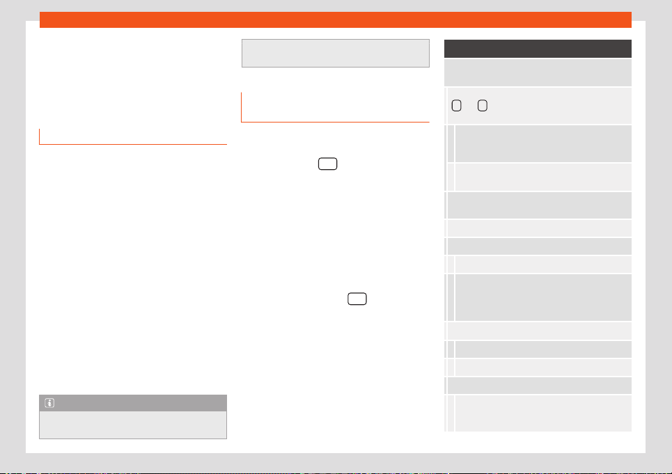
Infotainment System
been installed in a different vehicle, please go
t
o an authorised SEAT deal
er
.
If only the battery was disconnected, switch
on the ignition before turning the system on
again.
Change basic volume
Increase the volume: turn the volume con-
tr
ol clockwise.
Decrease the volume: turn the volume con-
trol anticlockwise.
Changes in basic volume are indicated by a
“volume bar” on the display, which appears
briefly.
It is possible to preset certain volume settings
and adjustments.
Mute system sound
●
Turn the volume control anti-clockwise
until it displays
.
●
OR: press the volume control briefly to
mute or unmute the system.
While the sound of the system is muted
(MUTE), the playback Media source stops.
Note
If the basic volume has been considerably
increased to pl
ay a certain audio source,
lower the volume again before switching to
another audio source.
System and function settings (SET-
UP)
Displaying menus settings and changing
settings
●
Press the button .
●
Select the desired adjustment range using
the adjustment button and confirm by press-
ing lightly.
●
Sel
ect the submenu using the setting but-
ton.
●
Select the desir
ed adjustment using the
setting button.
●
Confirm the changes by lightly pressing the
setting button.
●
Press the device button
, function but-
t
on t
o cl
ose the SETUP menu.
While changing the volume settings, the au-
dio source being played will be heard with
the settings you choose.
Available adjustment menus display
The settings that can be selected varies de-
pending on the country and the equipment in
question, and on the vehicle's equipment.
Menu option: submenus with repercussion
Radio Settings: Settings are made here that af
-
fect Radio mode.
Arrow keys: Set the behaviour of the arrow k
eys
and for changing stations in Radio mode
›››
page 115.
Preset list: The arr
ow keys are used to
switch between all of the savedstations in the se-
lected frequency band.
Station List: The arrow k
eys are used to
switch between all of the available stations.
Traffic programme (TP): Traffic st
ation an-
nouncements
›››
page 116.
Radio text: Radio text display
Delete memories: Delete stored stations.
Delete all: Delete all stored stations.
Selecting a special memory only deletes some
stations. Memories that contain a station are visi-
bly highlighted, identified with a frequency and
have a rubbish bin symbol at the end of the line.
FM station list
a)
:
Alphabetically: In alphabetical order.
Group: Sorted by groups.
Advanced FM settings:
RDS regional:
b)
: In areas without RDS cover-
age, services requiring RDS may be deactivated
(e.g. automatic station tracking)
›››
page 115.
112
Introduction
Menu option: submenus with repercussion
Automatic: Automatic change to a r
egional
RDS programme.
Fixed: Stations that support RDS are selected
manually.
Automatic frequency change (AF): Au-
tomatic station tr
acking
›››
page 115.
If the function is active, while driving it is always
changed to the frequency of the t
uned radio
station, which at that time is better tuned. This
happens even if a tuned regional broadcast is
interrupted.
If the function is disabled, the frequency
change is not performed. The tuned fr
equency
remains active until reception is interrupted.
Advanced DAB settings:
DAB traffic announcements: If there are
alerts of a traffic station available, they are
played directly in the active Radio DAB mode.
Traffic announcements of an FM traffic informa-
tion station are ignored. If this function is disabled,
or if the current DAB ensemble does not offer a TP
service, the traffic announcements of an FM traf-
fic station are played directly in the active Radio
DAB mode
›››
page 116.
Other DAB announcements: DAB announce-
ments (news, sports information, weather, warn-
ings, etc.) are played while the DAB Radio mode is
active.
Menu option: submenus with repercussion
DAB - DAB station tracking: Automatic
station tr
acking in Radio DAB mode. If the tuned
DAB station broadcasts on another channel when
you change location, it automatically switches to
that channel (factory setting).
DAB - FM automatic switching: Switch-
ing t
o the FM frequency band is permitted for au-
tomatic station tracking
›››
page 114.
Media settings: Here you can set the Media
mode settings.
Mix / Rep. incl. subfolders: It states that
r
andom play and repeat play may include possible
existing subfolders. The setting only affects the
playback of MP3/WMA files.
Selecting Bluetooth device: Selection of
the Bluetooth device to be used for playback or for
telephony.
Application connection: The settings of this
menu option are only available when a device is con-
nected.
Phone settings: Settings for pairing with a Blue-
tooth® compatible smartphone.
Sound settings:
Volume:
Maximum switch-on volume: Here you can
set the volume that must be adjusted when the
equipment is turned on. For adjusting use the +
and - buttons or the setting button.
Menu option: submenus with repercussion
Warnings: Here you can set the volume of tr
affic
station announcements (TP). For adjusting use
the +
and - buttons or the setting button.
Speed-dependent adjustment: The speed-
dependent volume increase function automati-
cally adjusts the volume based on the speed of
the vehicle
›››
page 114.
AUX Volume: To adapt the input v
olume of an
external audio source (AUX) to the playback
volume of the other audio sources.
BT Audio: To adapt the input v
olume of an ex-
ternal audio source (Bluetooth®) to the play-
back volume of the other audio sources.
Balance - Fader: To adjust the sound distribu-
tion.
Bass - Mid - High: To adjust the sound prop-
erties.
System Settings:
Screen:
Switch off screen (in 10 seconds):
The screen turns off automatically when no oper-
ation is performed during the set time. As soon as
one of the device buttons, function buttons or ro-
tary controls is activated, the display will be ac-
tive again and will show the last active dialogue.
Brightness: Screen brightness selection from
Maximum brightness to Maximum dark-
ness.
»
113

Infotainment System
Menu option: submenus with repercussion
Show clock in standby mode: When the
device is turned off
, the current time is shown on
the display.
Colour: Here you can select marking col
ours for
the screen.
Language: Here you can manually set the desired
l
anguage for the user interface. Alternatively, you
can let the instrument panel language be automati-
cally selected.
Bluetooth:
Bluetooth: Press to s
witch off Bluetooth®. All
existing connections are disconnected.
Visibility: Switch Bluetooth® visibility on and
off.
Visible: Bluetooth® visibility is switched on.
Not visible: Bluetooth® visibility is switch-
ed off. Bluetooth® must be switched on for
pairing a Bluetooth® device with the infotain-
ment system.
Forename: Display or change the name of the
device. This name will be displayed to other Blue-
tooth® devices in their Bluetooth® settings.
Paired devices: Viewing paired devices.
Switching Bluetooth® devices and individual
Bluetooth® profiles on and off.
Searching for a device: Search for visible
Bluetooth® devices that are within range of the
infotainment system. The maximum range is ap-
prox. 10 meters.
Menu option: submenus with repercussion
BT Audio (A2DP/AVRCP): If an external au-
dio sour
ce is to be connected to the infotainment
system via Bluetooth®, this function must be
switched on
›››
page 123.
Application connection
Data transfer active
Registry
Remove source safely: With this option you
can safely remo
ve an inserted SD card or a connec-
ted USB device.
Factory settings: Y
ou can r
est
ore the factory
settings of Radio, Media, Sound and System
separately or together.
System information: Status of technical data
of the device.
Copyright: Data of the software used.
a)
Valid only for the FM frequency band.
b)
This depends on the country and device in ques-
tion.
Oper
ation of speed-dependent v
olume in-
cr
ease
The speed-dependent volume increase func-
tion automatically adjusts the volume based
on the speed of the vehicle.
The volume increase can be adjusted in lev-
els from 1 to 7.
If the selected level is low, the volume only in-
creases slightly when the speed increases, if
on the contrary it is high, the volume increa-
ses considerably. On 0 the speed-dependent
volume increase is disconnected.
DAB-FM LINK operation
If the DAB station being listened to can no
longer be tuned in (e.g., there is no DAB cov-
erage), the device will try to find and tune the
same station on the FM frequency band.
To allow automatic station tracking on all fre-
quencies, the DAB station and the FM station
need to broadcast the station identification,
or to signal through DAB which FM station
corresponds to the same DAB station.
When the corresponding FM station has been
found, (FM) is displayed behind the name of
the station. If the corresponding DAB station
becomes available again, it returns to DAB
mode after a while.
If the signal is too weak and the DAB station in
question cannot be found again in the FM
band, the radio sound is muted.
114
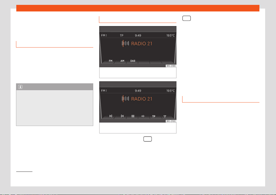
Operating modes
Operating modes
R
adio
Intr
oduction
The radio system is supplied in different ver-
sions depending on the country and the fea-
tur
es of the vehicle. Some systems also have
a DAB radio receiver. The control overview
contains the possible versions of the system
›››
page 109.
Note
●
Bear in mind that being in underground
parking l
ots, in tunnels, in areas with tall
buildings or mountains can interfere with
radio signals.
●
Foil or metal-coated stickers attached to
the windows may affect reception on vehi-
cles with a window aerial.
RADIO main menu
Fig. 110 RADIO main menu: selecting the fre-
quency band.
Fig. 111 RADIO main menu: Indication of preset
butt
ons.
●
Press equipment button
so start the
R
adio mode
.
Aft
er switching to Radio mode, the available
frequency bands (FM, AM
1)
and DAB
1)
) will be
shown on the bottom of the display. Press the
equipment button gain to display more
functions f
or the r
adio r
eceiver.
The following options are available:
●
Search next station.
●
Access a previously saved station.
●
Switching the TP function on and off
●
Save current station
›››
page 118.
The current station is shown in the middle of
the display. If the station allows for RDS and
the connection is good, instead of the fre-
quency, the name of the station will be
shown, e.g. RADIO 21.
RDS and automatic station tracking
RDS is a radio data service that enables to
displ
ay st
ation names, aut
omatic station
tracking and TP function (traffic information
station
›››
page 116).
With automatic station tracking, while driving
the equipment will switch to the frequency of
the radio station you are listening to that cur-
rently tunes better. If the tuning is bad, the
volume of the equipment may be briefly sup-
pressed while checking the alternative fre-
quencies (AF).
»
1)
This depends on the country and unit in ques-
tion.
115
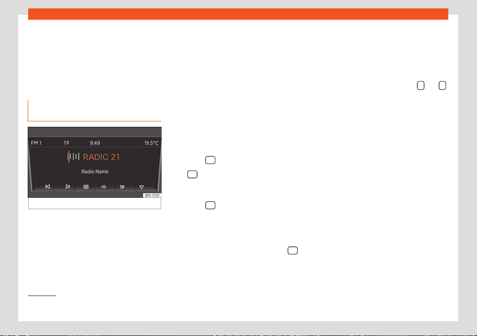
Infotainment System
RDS is not available in all places or on all ra-
dio st
ations.
Depending on the country and the equip-
ment, RDS and s
wit
ching to alternative fre-
quencies (AF) can be deactivated in the sys-
tem settings
›››
page 112.
TP function (traffic information sta-
tion)
Fig. 112
TP function activated.
The TP function is an RDS radio data service
›
›
›
page 115. If your equipment is fitted with
DAB
›››
page 118, you can also use the TP
function without having RDS
›››
page 116.
Using the TP function to track traffic informa-
tion is only possible if a station providing traf-
fic information can be tuned.
If the tracking of a traffic station is active (in-
dication: TP
›››
Fig. 112) traffic announce-
ments are played directly in Audio mode.
Tracking of traffic stations is not possible in
the AM frequency band
1)
.
Some stations without their own traffic infor-
mation support the TP function by broad-
casting traffic information from other stations
(EON). Traffic announcements of the corre-
sponding traffic station are played directly
during the active audio mode.
Activating and deactivating the TP func-
tion
●
Press the TP
function button.
If the TP function is activated in areas where
ther
e is no suppor
t f
or TP, the following
warning will appear on the screen: NO TP.
●
Press the TP
function button again to de-
activ
at
e the TP function again.
TP function activ
e
While the traffic station tracking is active and
ready for operation, in the FM mode the TP
›››
Fig. 1
12
function butt
on is displayed.
In Radio mode the station being listened to
must support the TP function, or there must
be a DAB or EON station available that sup-
ports the TP function. If neither of the require-
ments are met, it is not possible to track the
traffic station.
If the traffic station being listened to can no
longer be tuned, you will have to start a man-
ual search using the arrow buttons
and
›››
page 1
15
.
If you sear
ch for a station using the arrow but-
tons, the NO TP indication appears if the sta-
tion currently tuned is not compatible with TP.
In Media mode or while the equipment vol-
ume has been suppressed (mute), a traffic
station is automatically tuned in the back-
ground, as long as the station has a good sig-
nal. Depending on the situation, this opera-
tion may take some time.
Incoming traffic announcement (INFO)
In Audio mode, traffic announcements are
played directly when they are received.
●
If necessary, the radio gives way to the traf-
fic station (EON) while the announcement is
playing.
●
Media mode is interrupted and the volume
is set as adjusted.
1)
This depends on the country and unit in ques-
tion.
116
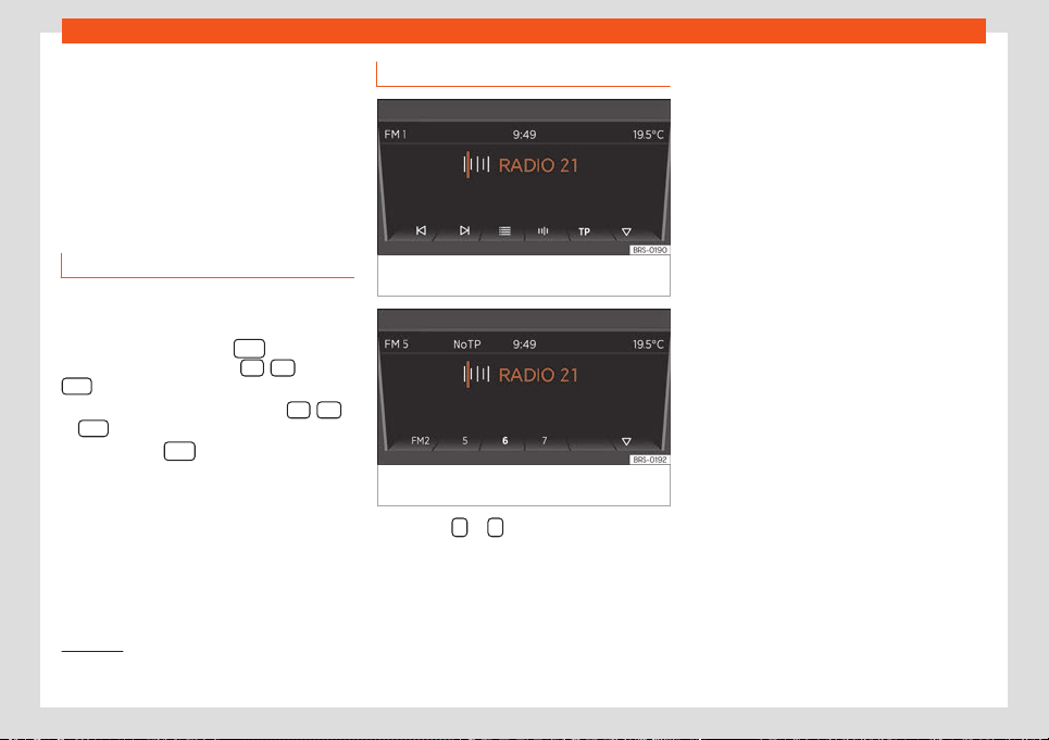
Operating modes
●
The v
olume of the tr
affic announcements
can be changed with the v
olume control .
This setting will also apply for subsequent an-
nouncements.
●
A pop-up message appears that allows
you to cancel the traffic announcement
(Cancel) or deactivate the TP function (De-
activate).
Changing frequency band
The frequency band selected (FM, AM
1)
or
D
AB
1)
) is sho
wn on the t
op left.
●
In Radio mode, press the
equipment
butt
on briefly t
o displ
ay the FM
, AM
1)
and
D
AB
1)
function butt
ons
›
›
›
Fig. 110.
●
Press one of the function buttons FM
, AM
or D
AB
to change the frequency band.
●
OR: Pr
ess the
equipment button a few
times t
o cycl
e thr
ough the different lower
function buttons.
Changing station
Fig. 113 Go to the next available station with
the arrow butt
ons.
Fig. 114 Changing the stations with the arrow
butt
ons is only possibl
e f
or saved stations.
●
Press the or arrow button on the sys-
t
em or the displ
ay.
Based on the mode sel
ected for the search
mode (Arrow buttons:) you can cycle
through either available or saved stations.
Manually tuning a station frequency
●
To select the desired frequency band
›››
page 115.
●
Press the function button of the frequency
band .
●
Rotate the setting button until the desired
frequency is shown on the display
(e.g. 89.9 MHz).
●
OR: Press one of the double-arrow buttons
›››
Fig. 116 until the frequency is shown on the
screen.
1)
This depends on the country and unit in ques-
tion.
117
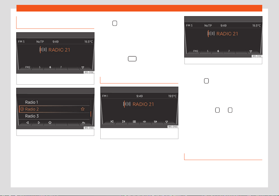
Infotainment System
Storing the station on the preset
butt
ons
Fig. 115
Station on the FM frequency band
st
or
ed in pr
eset button 6.
Fig. 116 Additional radio functions.
Stations that are already saved are overwrit-
t
en if another st
ation is st
ored in the same
preset button.
Assigning different preset buttons manual-
ly
●
Select the frequency band
›››
page 117.
●
Select station
›››
page 117.
●
Change to preset buttons. To do this, press
button
›
›
›
Fig. 117
●
Press and hold the desired preset button
until an audible signal is heard.
●
The current station (RADIO 21) will be saved
in this preset button.
You can update the station list by pressing
and holding the
equipment button or
using the function butt
on
›
›
›
Fig. 116.
Choosing memorised stations
Fig. 117
Radio mode indication: changing the
st
ation using the arr
o
w buttons.
Fig. 118 Saved stations.
●
Select the frequency band on which the
station is saved.
●
Pr
ess the
function button.
●
Press the pr
eset butt
on in which the st
ation
is saved briefly.
Depending on the settings, you can cycle
through the stations of a frequency band with
the arrow buttons
and (Arrow but-
tons:).
The st
or
ed st
ations can only be played if they
can be received at the current location.
Digital radio mode*
Introduction
Some systems also have a DAB radio receiv-
er
.
1
18
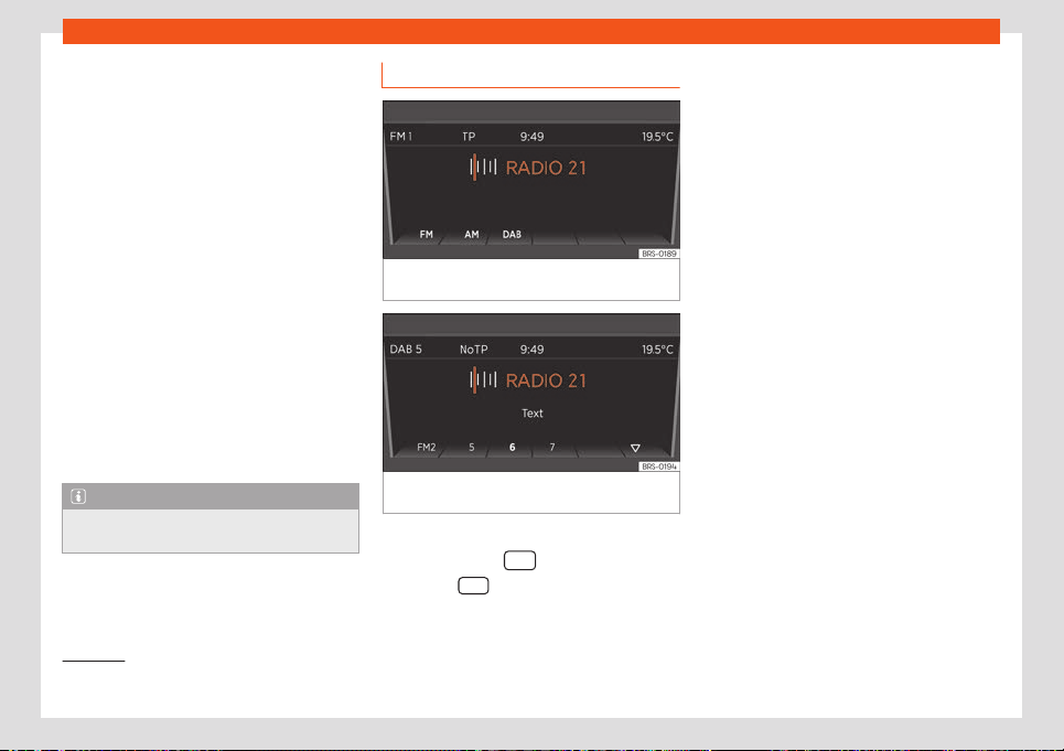
Operating modes
The DAB radio tuner supports the DAB, DAB +
and DMB audio tr
ansmission st
andar
ds.
The digital radio in Europe is transmitted
through band III frequencies (from 174 MHz to
240 MHz) and of band L (from 1,452 MHz to
1,492 MHz).
The frequencies of both bands are called
“channels” and have an abbreviation (e.g. 12
A).
In a channel, several available DAB stations
are grouped together in an “ensemble”.
DAB radio is not currently available every-
where. DAB radio mode displays in the
areas without DAB coverage. In the system
and function settings, it is possible to enable
changing to an FM station for this case
›››
page 112. In the system and function set-
tings, other settings can be configured for
station tracking and for the reproduction of
DAB announcements.
Note
Stations are responsible for the information
they transmit.
Operation
Fig. 119 RADIO main menu: Selecting memory
lev
el and frequency band.
Fig. 120 RADIO main menu: Indication of pre-
set butt
ons.
Starting the DAB radio mode
●
Press the button
.
●
Press the D
AB
›
›
›
Fig. 119 function button to
open DAB Radio mode.
After switching to DAB radio mode, the availa-
ble frequency bands (FM, AM
1)
and DAB
1)
) will
be shown on the bottom of the dis-
play
›››
Fig. 119. After about 5 seconds the
“preset keys”
›››
Fig. 120are displayed in-
stead .
The centre line of the screen displays the last
DAB radio (RADIO 21) tuned and it is played,
if it can still be tuned in the current location.
The ensemble currently selected (DAB 5) is
shown on the top line of the screen
›››
Fig. 120.
Changing the DAB and Autostore radio
station
This is operated in the same way as descri-
bed for FM and AM Radio mode
1)
›››
page 115.
Manually changing the DAB frequency
band channels
●
Turn the adjustment knob.
The selected channel is displayed in the cen-
tre of the screen. If the selected channel
broadcasts a DAB ensemble, its name will be
displayed at the top of the screen and the
first DAB station of that ensemble will be
played.
1)
This depends on the country and unit in ques-
tion.
119
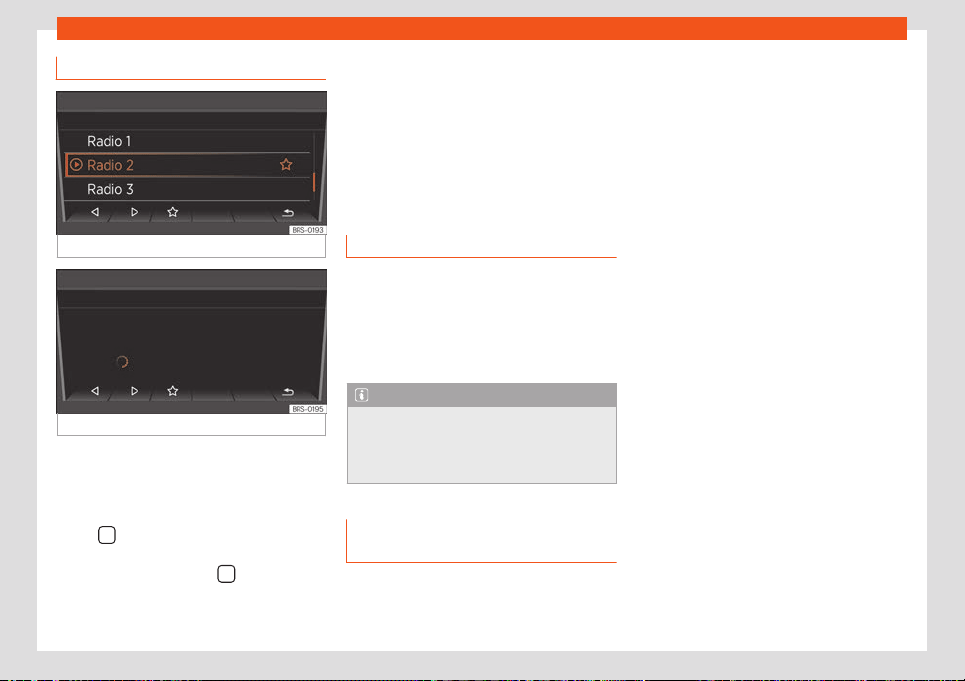
Infotainment System
Starting the station update
Fig. 121 Additional DAB functions
Fig. 122 Active station update.
During the station update, the equipment
sear
ches f
or the av
ailable station ensembles
in the place where it is located.
●
In the preset button view, press the function
button
›
›
›
Fig. 120 to display the addition-
al functions available
›››
Fig. 121.
●
Press the function button
›
›
›
Fig. 121, the
message that the station update is active is
displayed on the top bar of the screen
›››
Fig. 122.
●
The station update may take a few sec-
onds. The station update ends when the indi-
cation disappears.
During radio update the sound of the radio is
suppressed.
Media
Introduction
“Media sour
ces
” ar
e audio sources contain-
ing audio files on various different data stor-
age devices (e.g. external MP3 player). These
audio files can be played with their corre-
sponding applications or the radio's audio in-
puts.
Note
●
Do not use memory card adapters.
●
SEAT assumes no liabilit
y for any deterio-
ration or loss of files on data storage devi-
ces.
Requirements for Media sources
and audio fil
es
Limitations and indications
Dirt, high t
emper
at
ures and mechanical
damage can cause data media to fail. Con-
sider the indications provided by the manu-
facturer of the data media.
Consider copyright legislation!
The configuration of data media or of the
equipment or programmes used for recording
may cause some titles (tracks) or data media
to be unreadable. On the Internet, for exam-
ple, you can find information regarding the
best way to create audio files or data media
(compression rate, ID3 tag, etc.).
Complex folder structures can slow down da-
ta reading.
Playlists only establish a certain playback
order. The files are not saved in them. Play-
lists cannot be played if the files on the data
media are not saved to the path to which the
playlist refers.
120
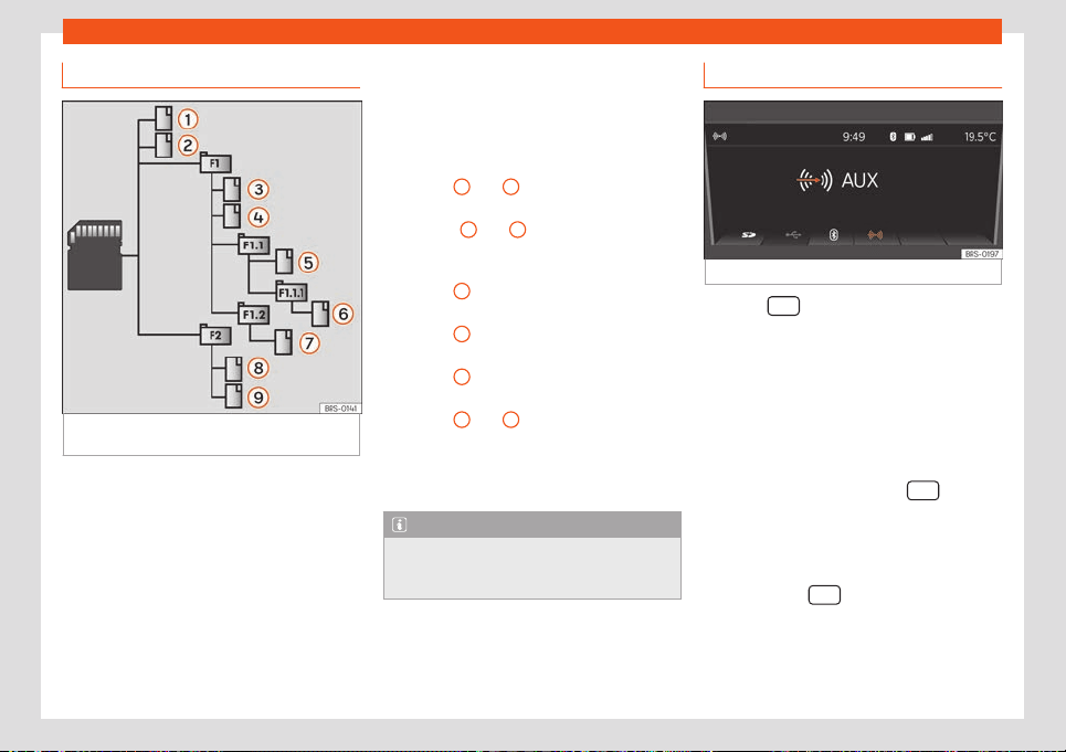
Operating modes
Playback order of files and folders
Fig. 123
Example of the structure of a data me-
dia with MP3 fil
es.
The audio files
st
or
ed on dat
a media are
often arranged by file folders
and playlists
to establish a certain playback order.
Depending on their name on the data media,
tracks, folders and playlists are ordered nu-
merically and alphabetically, respectively.
Subfolders are treated as folders and num-
bered according to the order in which they
are found in the data media.
The illustration
›››
Fig. 123 shows an example
of a conventional MP3 data media, contain-
ing tracks , folders and subfolders .
The tracks and folders of this data media are
displayed and played in the following order:
Track
1
and
2
in the r
oot directory
(ROO
T) of the dat
a media.
Tracks
3
and
4
in the first F1 f
ol
der of
the dat
a media root directory (indica-
tion: 01).
Track
5
in the first F1.
1
subf
older of fold-
er F1 (indication: 02).
Track
6
in the first F1.
1.
1
subfolder of
folder F1.1 (indication: 03).
Track
7
in the second F1.
2
subf
older of
folder F1 (indication: 04).
Track
8
and
9
in the second F2f
ol
der
(indication:
05).
Playlists are played in the same order as
the folders.
Note
The playback sequence can be modified
by selecting the playback mode (
MIX)
›››
page 125.
1.
2.
3.
4.
5.
6.
Select a Media source
Fig. 124 Select a Media source
Press the
equipment button to switch to
the Media mode
.
When s
wit
ching to the Media mode, the bot-
tom of the display shows the available Media
sources for a few seconds. The Media source
that is currently playing is highlighted .
Open the Media selection menu manually
and select a Media source
●
In the Media mode, press the
equip-
ment butt
on t
o displ
ay the Media selection
menu again.
●
Enable the Media source you want by
pressing the corresponding function button.
●
OR: Press the
equipment button again
t
o cycl
e thr
ough the available Media sources.
»
121
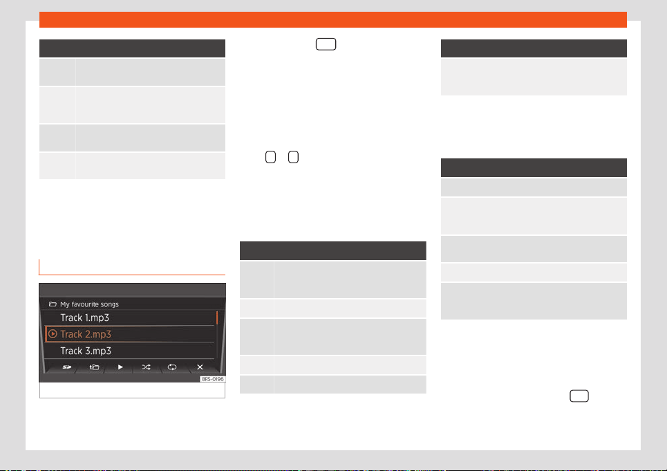
Infotainment System
Function button: Media source
SD card in the slot for SD cards
›››
page 122.
USB data storage in the USB socket
›››
page 123. You can see the location of
the connection in
›››
page 97.
*
Smartphone paired through Bluetooth
›››
page 123
External audio source connected to the
AUX-IN multimedia socket
››
›
page 124.
When a Media source that has already been
pl
ayed is sel
ect
ed again, playback is re-
sumed from the point at which it ended (ex-
cept for: AUX
›››
page 124).
SD card playback
Fig. 125
SD card playback: List of tracks.
●
Insert the SD card first with the cut corner
f
acing up and the titl
e on the l
eft in the slot for
SD cards.
●
Press the button
.
Pl
ayback continues with the l
ast Media
sour
ce selected. To play the SD card press .
In the folder view, browse with the function
button and the settings button. Press to
access a higher golder level and rotate the
settings switch to select the desired folder.
To switch to the previous or next track, press
either
or .
Hol
d one of the arr
o
w buttons to fast-forward
or rewind the track.
During playback, the following function but-
tons are available on the bottom of the dis-
play. Active function buttons are highlighted.
Function button: Meaning
a)
Playlist notification. Here you can also se-
lect a track dir
ectly with the settings but-
ton
›››
Fig. 125.
Previous track or rewind.
Play. It can also be pressed to stop the
pl
ayback. In this case
, the symbol
changes to
Next title or fast-forward
Random play.
Function button: Meaning
a)
To repeat a folder or track. The symbol
indicates that the current tr
ack is on re-
peat.
a)
Valid for Media sources: SD card, USB socket and
Bluetooth audio
In the list of playlists (butt
on ) the following
options are available:
Function button: Meaning
To change the main folder of the SD card.
To access a higher folder level. In the folder
list, you can sel
ect a differ
ent audio source
with
›››
page 121.
Play. It can also be pressed to stop the
playback.
R
andom play.
To repeat a folder or track. The symbol
indicat
es that the current tr
ack is on re-
peat.
Ejecting the SD card
Connect
ed dat
a st
orage devices must be
prepared before their disconnection in order
to remove them without damaging it.
●
Press the Infotainment button
and
then pr
ess
System settings
.
●
Sel
ect
Remove source safely
and then
SD Card. Aft
er correctly ejecting the data
122
Operating modes
storage device from the system, the function
butt
on becomes inactiv
e (gr
ey colour).
●
Now you can remove the SD card.
External data storage device in the
USB port
Depending on the country and device, there
might be one or sever
al USB ports in the
vehicle.
The location of the USB ports depends on
the vehicle in question .
Audio files on an external data storage device
connected to the USB port can be played
and controlled via the Infotainment system.
Where this manual refers to external data
storage devices, this means USB mass stor-
age devices containing supported audio files,
such as MP3 players, iPods™ and USB sticks.
Only compatible audio files are displayed.
Other files are ignored.
The rest of operations to use the external da-
ta device storage (changing tracks, selecting
tracks and enabling playback modes) are
carried out similarly to other audio sources
(e.g. “Playback from SD card”
›››
page 122.
Instructions and restrictions
The number of USB ports and their com-
patibility with Apple™ de
vices as well as with
other media players depends on the features.
The USB port supplies the usual USB volt-
age of 5 volts for a USB connection.
Due to the large number of different data
storage devices and various iPod™ and
iPhone™ generations available, it is not possi-
ble to guarantee fault-free operation of all
functions described here.
Take into account all other instructions and
limitations regarding requirements for media
sources.
Disconnecting
Connected data storage devices must be
prepared before their disconnection in order
to remove them.
●
Press the Infotainment button
and
then pr
ess Syst
em settings .
●
Select R
emove source safely and then
SD Car
d
. After correctly ejecting the data
st
or
age de
vice from the system, the function
button becomes inactive (grey colour).
●
Now the data storage device can be dis-
connected.
Bluetooth® playback*
Connection of a safe audio source through
Bluetooth
Bluetooth® audio mode all
ows audio files
that are being played on a Bluetooth® audio
source (e.g. a modile phone) connected by
Bluetooth® through the vehicle’s speakers
(Bluetooth® audio playback).
Requirements
●
The Bluetooth® audio source must be com-
patible with the A2DP Bluetooth® pr
ofile.
●
In the Bluetooth Settings menu the
BT Audio (A2DP/AVRCP) function
must be on.
St
ar
ting Bluet
ooth® audio transmission
●
Switch on Bluetooth® visibility on the exter-
nal Bluetooth® audio source (e.g. mobile
phone).
●
Lower the base volume on the Infotainment
system.
●
Press the button
.
●
Press the function butt
on t
o sel
ect Blue-
tooth® as a media source.
●
Start searching for the desired Bluetooth®
device.
●
Please refer to the instructions on the
screen of the infotainment system and on the
Bluetooth® audio source regarding the rest of
the procedure.
»
123
Infotainment System
You may also need to manually start play-
back on the Bluet
ooth® audio sour
ce
. When
playback ends on the Bluetooth® audio
source, the infotainment system remains in
Bluetooth® mode.
Controlling playback
The extent to which the Bluetooth® audio
source can be controlled via the Infotainment
system depends on the Bluetooth® audio
source that is connected.
With media players that support the AVRCP
Bluetooth® profile, playback on the Blue-
tooth® audio source can be automatically
started or stopped when the unit is switched
to Bluetooth® Audio mode or to a different
audio source. In addition, it is possible to view
or change the track via the Infotainment sys-
tem.
WARNING
Do not perform the pairing and connection
process while driving. This may cause an
accident
!
Note
●
Due to the lar
ge number of possible Blue-
tooth® audio sources, it is not possible to
guarantee fault-free operation of all de-
scribed functions for all these sources.
●
To operate the media and phone with the
connected Bluetooth® device, please read
the manufacturer’s electronic Instructions
Manual.
●
Only use compatible Bluetooth® devices.
You can request inf
ormation about compat-
ible Bluetooth® products at a SEAT Author-
ised Service or online.
External audio source connected to
the AUX-IN multimedia socket
The AUX-IN multimedia jack can be found on
the fr
ont of the r
adio
›
››
page 109. It can only
be used with a 3.5 mm jack connector.
A connected external audio source is played
over the vehicle speakers andcannot be
controlled via the radio system controls.
The AUX-IN multimedia connection must be
activated in the system settings so it can be
displayed on the Media selection menu
›››
page 121.
Connecting an external audio source to
the AUX-IN multimedia socket
●
Lower the base volume on radio.
●
Connect the external audio source to the
AUX-IN multimedia socket.
●
Start playback on the external audio
source.
●
In the Media mode, press the
equip-
ment butt
on t
o displ
ay the Media source se-
lection menu again
›››
page 121.
●
Press the function button.
The output volume of a connected external
audio source should be adjusted to the vol-
ume of the other audio sources.
Adapting the playback volume
If you need to increase the playback volume
for the external audio source, first lower the
base volume on the radio system.
If the sound from the external audio source is
too low, increase the output volume on the
external audio source, if possible. If this is not
enough, adjust the input volume in the sys-
tem settings to Level 2 or Level 3.
If the sound from the connected external au-
dio source is too loud or distorted, lower the
output volume on the external audio source,
if possible. If this is not enough, change the
input volume to Level 2 or Level 1
Note
●
When the playback from the e
xternal au-
dio source ends or the connection to the
AUX-IN socket is interrupted, the radio goes
back to the AUX menu.
●
Interference noise may be heard if the ex-
ternal audio source is powered from the 12-
volt power socket of the vehicle.
124
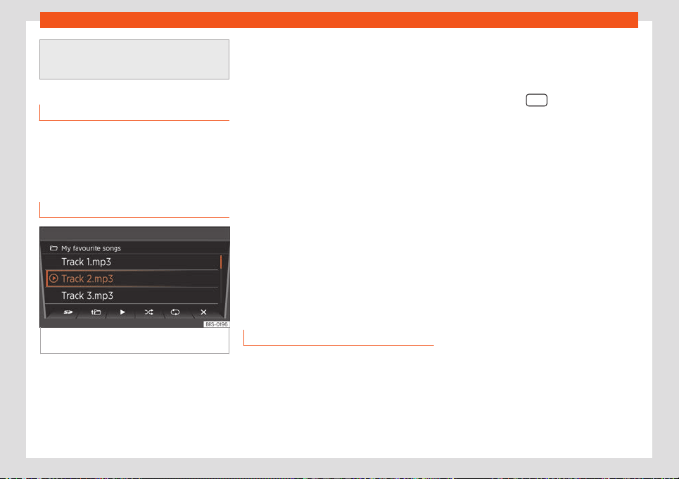
Operating modes
●
Please read and observ
e the manufac-
turer's instruction manual for the external
audio source.
Track information display
In the case of audio files that contain addi-
tional title information (ID3 t
ag in MP3 files)
the different stored title data can be dis-
played
›››
Fig. 125.
Changing the playback mode
Fig. 126
SD card playback: Possible playback
modes.
Consider the playback order of files and fold-
ers
›
›
›
page 121.
Selecting playback modes
●
Press the function button to start the corre-
sponding playback mode. The function but-
ton appears underlined.
Random playback: The tracks are played
in random order. Random playback remains
active for the corresponding Media source
until it is deactivated from that source.
Repeat: The tracks of the playlist are re-
peated.
●
Press the function button again to end
the active playback mode in the track being
played.
●
Press the function button again to only
repeat the track being played. After pressing
once more, the repeat function is deactiva-
ted.
Telephone
Connection and operation
Requirements for phone management:
Y
our mobil
e phone s connect
ed to the Info-
tainment System through Bluetooth®.
Connection between the mobile phone
and the Infotainment System
●
Please observe the information on the
page 123, Bluetooth® playback*.
●
Press the button
.
●
On the Bluetooth® menu of your mobile
phone
, sear
ch f
or the name shown on the dis-
play.
●
If necessary, take into account the
›››
page 123 notifications.
●
To complete the pairing process, respond
to the requests of both devices.
Changing the volume
Media and phone call playback from a con-
nected mobile phone will be conducted
through the speaker of the vehicle.
If voice control is enabled on the mobile
phone connected, voice communication will
also take place through the vehicle speaker.
The playback volume can be modified with
the volume control .
Moreover, the volume of navigation an-
nouncements can be adjusted in the Sound
settings menu.
If the volume of the system is muted (notifica-
tion: ), media sources that are playing on
the connected Smartphone are also interrup-
ted.
»
125
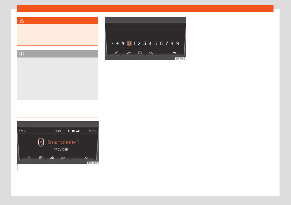
Infotainment System
WARNING
General, mandatory, legal and country-
specific instructions and laws for the use of
mobil
e phones inside the vehicle must al-
ways be considered.
Note
●
To operat
e the media and phone with
your mobile phone plugged in, please read
the electronic Instructions Manual of the
manufacturer.
●
Only use compatible Bluetooth® devices.
You can request information about compat-
ible Bluetooth® products at a SEAT Author-
ised Service or online.
Functions of the phone
Fig. 127 Phone disconnected.
Fig. 128 Dial a number with the menu button.
After correctly connecting the phone, you
cam manage the call functions of your
paired mobile phone thr
ough the Infotain-
ment System
›››
Fig. 127.
Dial number:
Press the
›››
Fig. 127 function button to dis-
play the dial screen
›››
Fig. 128. Here you can
choose a number with the right switch and
confirm it by pressing. If the number is cor-
rect, the call can be started through the
speaker
›››
Fig. 128.
Moreover, the following options are available
here:
●
: calls the emergency number
1)
.
●
: connects t
o a SEAT f
ault service
1
)
.
●
: connects to the SEAT information hot-
line
1 )
.
●
: starts call to your v
oice mail. For this
purpose, your mailbox number will be reques-
ted the first time you select it.
Phonebook:
Press the
›››
Fig. 127 function button to dis-
play the phonebook. The phonebook con-
tains all the contacts of your mobile phone,
which you can select one by one with the
right switch and establish a connection by
pressing it, or either access a list with availa-
ble numbers first. For this purpose, during the
first connection, you have to confirm the
transfer of your mobile phone contacts. With
the star button you can save a contact as a
fast-dial number.
Call log:
Press the
›››
Fig. 127 function button to dis-
play call log. All the calls from your mobile
phone will be shown here once you have
confirmed the transfer of your contacts from
your phone.
●
All: shows all calls in chronological order.
●
: only shows missed calls.
●
: only sho
ws received calls.
●
: only shows outgoing calls.
The function button bookmarks an entry.
1)
Not available in all countries.
126
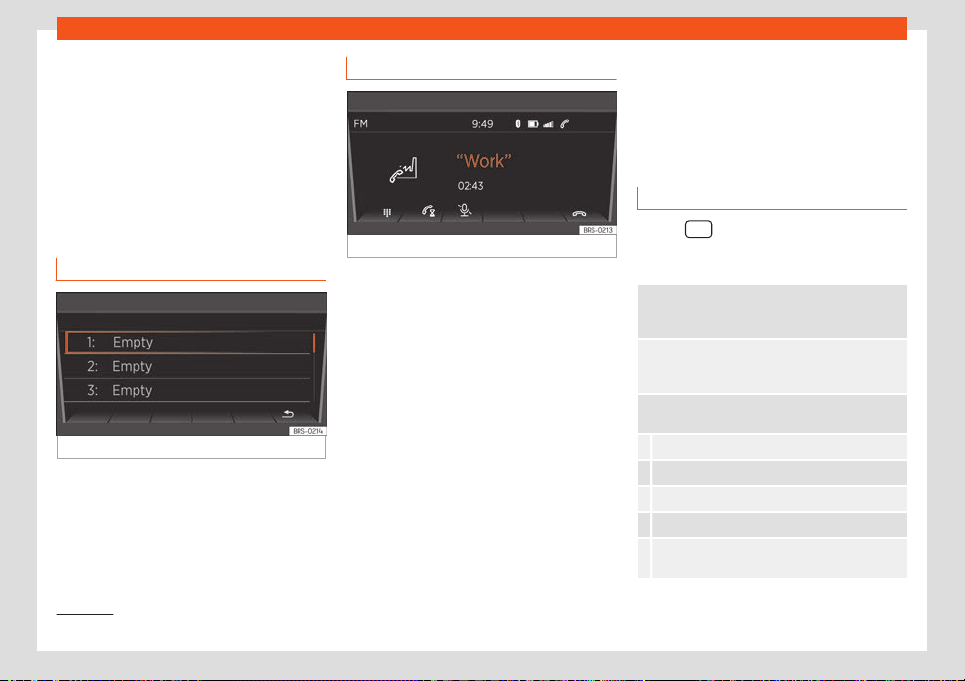
Operating modes
Voice mail:
Pr
ess the
›››
Fig. 127 function button to ac-
cess your voice mail inbox. For this purpose,
your mailbox number will be requested the
first time you select it.
Emergency call:
1)
Press the
›››
Fig. 127 function button to
make an emergency call.
Favourites
Fig. 129
Fast-dial
Fast-dial:
Pr
ess the
›
›
›
Fig. 127 function button to
open the fast-dial list
›››
Fig. 129. Select an
empty slot of your fast-dial list to access the
phonebook, where you can choose a contact
as a fast-dial number. Select a used slot to di-
al its corresponding phone number.
Call by telephone
Fig. 130 Ongoing call.
Incoming call:
If you r
eceiv
e a call, you hav
e three options:
●
accepting the call with the function but-
ton.
●
muting the ringtone with the function
button.
●
rejecting the call with the function but-
ton.
Active call:
If you accept the incoming call, you have the
following options during the call
›››
Fig. 130:
●
Press the function button to emit DTMF
tones (e.g. to operate an answering ma-
chine).
●
Press the function button to pause the
phone call.
●
Press the function button to mute the mi-
crophone.
●
Press to end the call.
Settings of a connected phone
Use the equipment button to access the
phone's settings: The follo
wing options are
available:
Hands-free: If there is an ongoing call, you can
continue the call on the mobil
e phone or transfer it
back to the Infotainment System.
Phone selection: Cycle through the phones r
ec-
ognised by the Infotainment System or search for
new devices.
User profile: Change the settings of the phone
currently connected:
Manage your fast-dial numbers (e.g. delete one).
Set or change voice mail numbers.
Sort your phonebook.
Download your contacts again.
Activate/deactivate mobile phone notifications
when turning off the engine.
»
1)
Not available in all countries.
127
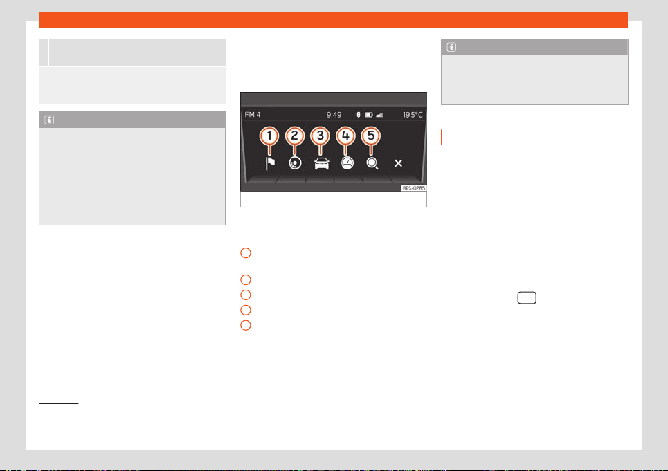
Infotainment System
Select a ringtone (only if the phone is not emitting
any sounds).
Bluetooth®: Here you can change the connection
settings of the tel
ephone. For instance, you can de-
lete known devices.
Note
●
If a device connected by Bluet
ooth® sup-
ports this profile, it will always be used at
the same time for calls and audio through
Bluetooth®.
●
To operate the media and phone with
your mobile phone plugged in, please read
the electronic Instructions Manual of the
manufacturer.
Drive Mii App*
Intr
oduction
Fig. 131
Application connection main menu.
The connected smartphone offers the follow-
ing options:
Navigation o
v
er the smartphone with
navigation announcements on the r
adio.
ECOTRAINER display.
Driving data notifications.
Notifications from the odometer, etc.
Search in all fields.
You can also use the telephone function of
your connected smartphone over the radio
using the right switch.
1
2
3
4
5
Note
To operate the telephone and multimedia
aspects and for navigation with the con-
nected smar
tphone, read the instructions
manual of the manufacturer.
Connection and operation
Requirement: Your smartphone is connected
t
o the radio through USB
›››
page 123 and the
SEAT application to connect the smartphone
to the radio is installed on your smartphone
1)
.
Place the smartphone in its socket and turn it
on. Removal and installation of the equip-
ment and the socket are described in
›››
page 98.
Connection between smartphone and ra-
dio
●
Press the button
to open the main
menu.
●
Afterwards, select and enable the Connec-
tion of the application function with
the settings butt
on.
Once the connection is est
ablished, you can
manage r
adio music playback with the
1)
For more information about the application re-
garding install
ation and use, take into account
the information provided with the vehicle.
128
Connectivity
smartphone. You can start the navigation on
the smartphone and list
en t
o the navigation
announcements on the audio syst
em of the
vehicle.
Instructions for navigation
Acoustic navigation announcements will be
played on the speakers of the vehicle. Re-
garding this, take into account the instruc-
tions in Adjusting the volume
›››
page 129.
You can manage this from the connected
smartphone
›››
page 129.
Changing the volume
Multimedia playback, navigation announce-
ments and phone calls emitted by the con-
nected smartphone will be played on the
speakers of the vehicle.
The volume of the traffic announcement can
be modified with the volume control .
You can also adjust the volume of the naviga-
tion announcements on the Sound settings
menu.
When the volume of the system is muted (no-
tification: ), playback of multimedia sour-
ces played on the connected smartphone is
also interrupted.
Note
●
For more inf
ormation about the installa-
tion and use of the application, see the in-
formation provided with the vehicle.
●
To operate the media and phone and to
navigate with your Smartphone plugged in,
please read the electronic Instructions
Manual of the manufacturer.
●
If a device connected by Bluetooth® sup-
ports this profile, it will always be used at
the same time for calls Bluetooth® audio
and the connection for apps.
●
Only use compatible Bluetooth® devices.
You can request information about compat-
ible Bluetooth® products at a SEAT Author-
ised Service or online.
Connectivity
Cybersecurit
y
Intr
oduction
Control units with integrated eSIM card, inter-
faces and connections for multimedia and di-
agnosis ar
e connectivity components
through which data and information can be
exchanged between the vehicle and external
devices or the Internet
›››
. The connectivity
components mainly include the f
oll
o
wing:
●
Connection socket for diagnosis
●
Control units with integrated eSIM card
●
Telephone interface
●
Media Control
●
App-Connect
●
WLAN access point (hotspot)
●
Bluetooth connection
●
USB connection
●
AUX-IN multimedia socket
●
Slot for SD cards
●
Slot for SIM cards
The connectivity components are key points
in cybersecurity. The connectivity compo-
nents in particular, but also other control
units, are fitted with locking mechanisms that
»
129
Infotainment System
minimise the risk of unauthorised third parties
accessing the v
ehicl
e
’s systems.
Software and locking mechanisms mounted
on the vehicle are being developed continu-
ously. As in the case of computers or mobile
phone device operating systems, software
and locking mechanisms mounted on the ve-
hicle can also be updated non-periodically.
In general, software updates improve the se-
curity, stability and speed of execution of ve-
hicle systems that have already been manu-
factured.
You can actively contribute to reducing the
risk of unauthorized third parties accessing
the vehicle systems and their functions:
●
Do not use data storage devices, Bluetooth
devices or mobile phone devices that contain
manipulated data or malicious software in
the vehicle.
●
Only get vehicle repair and maintenance
work done at specialised workshops. SEAT
recommends visiting a SEAT dealership for
this.
WARNING
Computers, data storage devices and mo-
bile phone devices that connect t
o the In-
ternet or that are used on public or private
networks can be infected by manipulated
data and malicious software.
●
In addition to taking the gener
ally known
precautionary measures when using the In-
ternet, you should protect your computer,
your data storage devices and your mobile
phone with an appropriate antivirus pro-
gram and regularly update your login de-
tails.
WARNING
The risk of unauthorized third parties ac-
cessing the v
ehicle's functions and contr
ol
units through malicious software or an In-
ternet attack cannot be ruled out despite
the locking mechanisms fitted to the vehi-
cle. If malicious software is introduced into
the vehicle, it can influence, deactivate or
control the control units and vehicle func-
tions and cause serious accidents and fatal
injuries.
●
Malicious software can also access data
and information stored in control units, the
infotainment system, connected data stor-
age devices and paired mobile phone devi-
ces.
●
If the vehicle operates differently than
usual or reacts or behaves strangely, re-
duce the speed immediately (whenever
possible) in a controlled manner and go to
the nearest specialized workshop without
delay or request the help of specialized
personnel, e.g. to tow the vehicle.
SEAT CONNECT
Intr
oduction
SEAT CONNECT groups together different
SEAT CONNECT service portfolios that off
er
additional functions for your vehicle, e.g. Re-
mote Access. These services can be execu-
ted, for example, from home with a computer
or away from home with a mobile phone de-
vice (smartphone or tablet).
The vehicle and the computer or mobile
phone are connected to each other by an In-
ternet connection.
SEAT CONNECT is equipment that is not
available in all countries, which is made up of
several portfolios. It has to be activated on-
line before it can be used and it is subject to a
country-dependent time use limitation.
Both the SEAT CONNECT service portfolios
offered by SEAT and individual services can
be modified, cancelled, deactivated, reacti-
vated, renamed and extended, even without
prior notification.
On the website https://my.seat you can cre-
ate a user account, consult descriptions of
SEAT CONNECT services and find out more
about them.
The availability of SEAT CONNECT services
can vary depending on the model and equip-
ment.
130
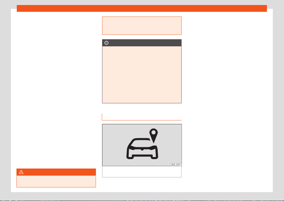
Connectivity
Activating SEAT CONNECT
SEAT CONNEC
T can be activ
at
ed at
https://my.seat or, in some vehicles, directly
in the infotainment system:
●
First step: create a user account.
●
Second step: add your vehicle to the user
account.
●
Third step: activate SEAT CONNECT.
Description of services
Before running SEAT CONNECT services,
read and take into account the correspond-
ing services description. Descriptions are up-
dated non-periodically and are available on-
line. Always use the most up-to-date version
of the corresponding service description.
The initial service allocation shown here cor-
responds to the first generation of SEAT
CONNECT fitted to the Mii electric:
●
Vehicle status incl. doors and lights
●
Driving data
●
Parking position
●
Remote air conditioning
●
Electrical power manager
●
Departure times
WARNING
In areas with insufficient mobile phone and
GPS cover
age, neither emergency calls or
phone calls can be made, and data cannot
be transmitted.
●
Change l
ocation if possible.
CAUTION
The vehicle may be damaged by factors
outside SEAT
’s contr
ol. These may be spe-
cifically:
●
Insufficient network coverage
●
Misuse of mobile terminals
●
Data loss during transmission
●
Unsuitable or defective third party appli-
cations
●
Malicious software on data storage devi-
ces, computers, tablets or mobile phones
Legal provisions
Fig. 132
Marking for vehicles that send track-
ing inf
ormation.
When contracting SEAT CONNECTION serv-
ices f
or your v
ehicl
e, you are obliged as a
contractor, for the purposes of the data pro-
tection law, to inform any driver of the vehicle
that it can transmit or receive data online.
This also applies if the vehicle is sold or lent.
Not taking into account this obligation to in-
form, can infringe certain rights of the occu-
pants.
GPS tracking: consult all occupants
Some SEAT CONNECT services need vehicle
data to determine at any given time whether
the vehicle is being used or moving within de-
fined speed ranges, where it has been parked
or if it is being used in an established geo-
graphical area. This information is displayed
in the MySEAT web portal and in the SEAT
CONNECT app.
Therefore, before moving off, ask all the vehi-
cle occupants if they agree with the activa-
ted services. If they do not, deactivate the
service in question (if possible) or do not al-
low the occupants to use the vehicle. If you
do not take this into account, you may in-
fringe upon certain rights of the occupants.
GPS tracking: marking
If the vehicle has a factory assembled control
unit that transmits the its current geographi-
cal position and speed, the vehicle usually
has this marking
›››
Fig. 132 (e.g., on the
»
131
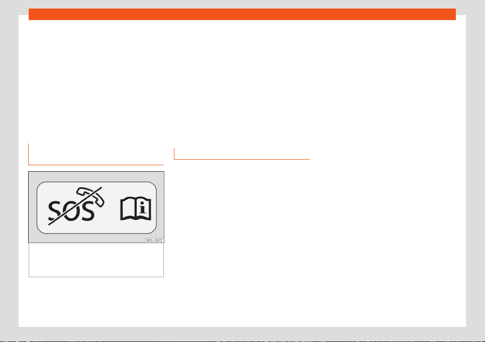
Infotainment System
roof console). The absence of this marking
›
›
›
Fig. 132 in the vehicle does not guarantee
that the control unit does not transmit the ve-
hicle’s current geographical position and
speed.
Personal data
SEAT collects, processes and uses the user's
personal data within the framework of the
law. On the SEAT website you can consult the
current data confidentiality statement.
Deactivating SEAT CONNECT serv-
ices
Fig. 133
Sticker subsequently affixed to the
v
ehicl
e that indicat
es that the SEAT CONNECT
services have been permanently disconnec-
ted.
To permanently deactivate the SEAT CON-
NEC
T functionalit
y, go t
o a specialized work-
shop and request the deactivation of the
control unit called “Emergency call module
control unit and communication unit”.
Once the “Emergency call module control
unit and communication unit” has been de-
activated, the workshop in question generally
affixes the sticker
›››
Fig. 133 to the vehicle,
e.g. to the roof console. The sticker indicates
that “Remote Access” services do not work.
If you sell the vehicle or lend it for a long peri-
od of time, warn the buyer or the user that the
services and the control unit are deactivated.
Faults
Even if the prerequisites for the use of SEAT
CONNEC
T services ar
e met, ther
e may be
factors beyond the control of SEAT that inter-
fere with the execution of such services or
prevent them. These may be specifically:
●
Maintenance, repair, deactivation, software
update and technical expansion of telecom-
munication equipment, satellites, servers and
data banks.
●
Change of the mobile telephony standard
for the transmission of mobile data by the tel-
ecommunications service provider, for exam-
ple, from UMTS to EDGE or GPRS.
●
Disconnection of an existing mobile phone
standard by the telecommunications service
provider.
●
Interference, disturbance or interruption in
the reception of the mobile phone and GPS
signal due to aspects such as high-speed
driving, solar storms, meteorological influen-
ces, topography, blocking equipment and the
intensive use of mobile phones in the radio
cells in question.
●
When in areas with zero or insufficient mo-
bile telephony or GPS coverage. Also, for ex-
ample, in tunnels, confined areas between
very tall buildings, garages, underpasses,
mountains and valleys.
●
External information from third party sup-
plies available with limitations, incomplete or
incorrect, e.g. representations of maps.
●
Countries and regions where SEAT CON-
NECT is not offered.
132
Drive system and driving
Driving
Driv
e syst
em and driving
Driving indications
El
ectric drive system functions.
Delivery of power from the electric engine
The maximum torque of the el
ectric engine is
available immediately after pressing the ac-
celerator pedal.
Brake energy recuperation (charging)
When braking the vehicle, electric power is
generated through the electric engine and
stored in the high-voltage battery
›››
page 134. This also occurs to a lesser ex-
tent when the vehicle moves by inertia or
drives downhill in the deceleration phase.
As the charge level of the high-voltage bat-
tery increases, the recuperation reduces and,
thus, the effect of the engine brake. When the
high-voltage battery is fully charged, no en-
ergy recuperation takes place and the effect
of the engine brake is not available
›››
.
The ener
gy r
ecuper
ation can be displayed
on the instrument panel display or in the ap-
plication installed on the smartphone.
Slow travel function
The slow travel function consists of driving
slowly, at about 5 km/h (3 mph), forward or
reverse without pressing the accelerator ped-
al.
The slow travel function is activated automat-
ically:
●
When the drive system is connected and
the selector lever is placed in the D/B posi-
tion or the reverse gear is engaged R.
●
Each time the selector lever is changed to
position D/B or R.
●
When the vehicle is travelling less than 10
km/h (6 mph) and the driver's door is opened.
●
When the vehicle is stopped and the brake
pedal is pressed, the driver's door opens or
the driver unbuckles the seat belt.
The slow travel function is deactivated if,
when the driver's door is closed and the seat
belt is in place:
●
The vehicle is travelling at more than 10
km/h (6 mph).
●
The selector lever is in position P or N.
●
If, after connecting the drive system, the ve-
hicle was once in motion.
WARNING
Any accidental movement of the vehicle
could result in serious injury.
●
When the drive system is connect
ed and
the selector lever is in the D/B position or
reverse gear is engaged, the vehicle must
be stopped by pressing the brake pedal.
Even when the drive system is switched off,
it is possible that the power transmission is
not interrupted completely and the vehicle
continues to “move slowly”.
●
Never leave the vehicle with the selector
lever in the N or D/B position. The vehicle
will roll downhill regardless of whether the
drive system is connected or not.
WARNING
As the level of charge of the high-voltage
battery increases, the eff
ect of the engine
brake caused by the recuperation of the
brake energy is reduced and may even be
completely cancelled out.
●
Slow down before starting a long dis-
tance with a steep descent.
●
During a long distance with a steep de-
scent, reduce the speed with the vehicle
brake.
133
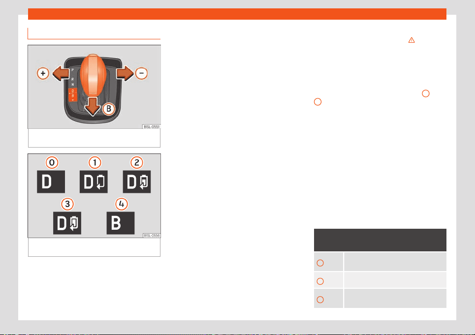
Driving
Brake energy recuperation
Fig. 134
On the selector lever: connect the
br
ak
e ener
gy recuperation.
Fig. 135
On the instrument panel display: indi-
cation of r
ecuper
ation l
evels.
The brake energy recuperation can generate
a br
aking eff
ect. This br
aking effect depends
on the selected driving programme and the
level of charge of the high-voltage battery.
When braking the vehicle and when the vehi-
cle moves by inertia or travels downhill in the
deceleration phase, electric power is gener-
ated by the electric engine and stored in the
high-voltage battery. The electric engine
then operates as an alternator and produces
a engine brake effect. This process is called
brake energy recuperation.
The status of the recuperation is indicated in
the power display of the instrument panel
›››
page 57. When recuperation is active, the
needle goes to the green area of the display.
The current recuperation level is displayed on
the instrument panel display
›››
Fig. 135.
Given the case, in the application installed on
the smartphone you can view a statistic of
the energy recuperated over the last 30 mi-
nutes. Check the electronic instruction man-
ual of the application for this.
The effect of the engine brake is more or less
intense depending on the level of recupera-
tion. If the recuperation is very intense, the
brake light of the vehicle may also be switch-
ed on. As the charge level of the high-voltage
battery increases, the recuperation reduces
and, thus, the effect of the engine brake.
When the high-voltage battery is fully charg-
ed, no energy recuperation takes place and
the effect of the engine brake is not available.
When the vehicle detects that road condi-
tions do not allow safe contact between the
wheels and the road, the energy recupera-
tion is automatically reduced and, therefore,
the effect of the engine brake
›››
.
Sel
ect a r
ecuper
ation level
There are a total of 4 brake energy recupera-
tion levels. You can switch between recupera-
tion levels 1 to 3 by pressing the selector lever
slightly sideways towards
›››
Fig. 134
+
and
–
:
●
Push the selector lever slightly to the l
eft
t
o
increase one recuperation level.
●
Push the selector lever slightly to the right
to decrease one recuperation level.
●
Push the selector lever to the right for a few
seconds to disconnect the recuperation.
To increase to recuperation level 4, push the
selector lever slightly to position B.. Pushing it
again gently in the direction of the arrow , it
is changed back to position D and the last re-
cuperation level that was selected is activa-
ted.
Recuperation level
›››
Fig. 135 and mean-
ing:
0
The vehicle moves by inertia. Recupera-
tion only takes pl
ace when braking.
1
Slight recuperation, recuperation level 1
2
Medium recuperation, recuperation lev-
el 2
134
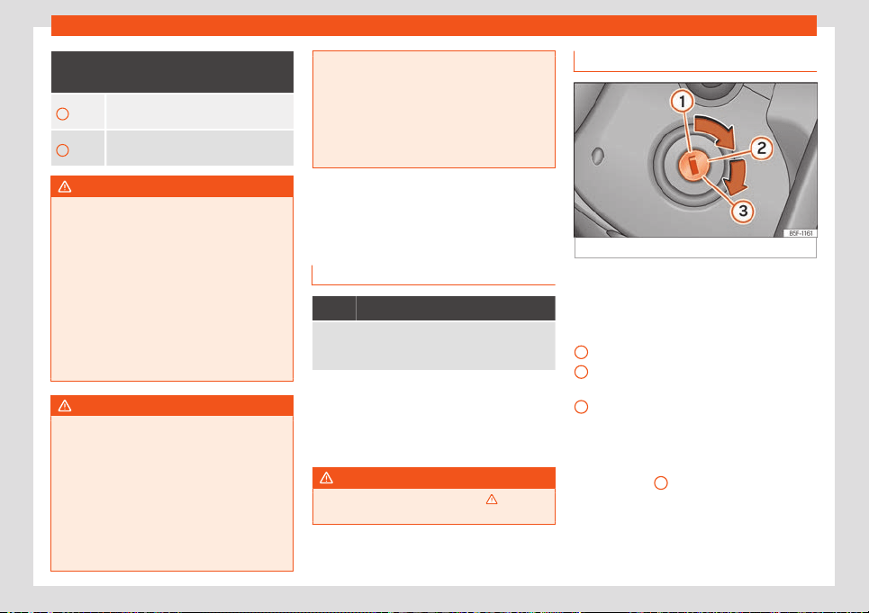
Drive system and driving
Recuperation level
›››
Fig. 135 and mean-
ing:
3
Intense recuperation, recuperation level
3
4
Very intense recuperation, recuperation
level 4
WARNING
A medium, intense or very intense recuper-
ation of brake ener
gy can cause loss of
traction and the vehicle skidding, especial-
ly on slippery roads. This could cause loss
of control of the vehicle, accidents and se-
rious injury.
●
Never use a medium, intense or very in-
tense brake energy recuperation if the con-
ditions of visibility, weather, road and traf-
fic do not allow it, or if it endangers other
users on the road due to the acceleration
of the vehicle and the driving style.
WARNING
As the charge level of the high-voltage bat-
tery increases, the eff
ect of the engine
brake caused by the recuperation of the
brake energy is reduced and may even be
completely cancelled out. This puts much
greater demand on the vehicle’s brakes.
●
When charging the high-voltage battery
in high-altitude locations (e.g. on top of a
mountain pass), never fully charge it. In this
way, when descending the mountain the
engine braking effect through recuperation
will be enabled.
●
Slo
w down before starting a long dis-
tance with a steep descent.
●
During a long distance with a steep de-
scent, reduce the speed with the vehicle
brake.
Connecting and disconnect-
ing the drive system
Contr
ol lamps
It lights up yellow
Failure in engine management.
Go immediately to a specialised w
orkshop and re-
quest the electric drive system be checked.
Several warning and control lamps light up
f
or a f
e
w seconds when the ignition is switch-
ed on, signalling that the function is being
verified. They will switch off after a few sec-
onds.
WARNING
Observe the safety warnings
›››
in Con-
trol and warning l
amps on page 66.
Ignition lock
Fig. 136
Ignition key positions.
When there is no vehicle key in the ignition
l
ock
, the st
eering column lock may be activa-
ted.
Positions of the vehicle key
›››
Fig. 136
Ignition off. The key can be removed.
Ignition is switched on. The steering lock
may be released.
Press the brake pedal if the control lamp
lights up green. Connection of the
drive system. When the drive system is
connected, release the key. When it is re-
leased, the key returns to position
›››
Fig. 136
2
.
W
arning that the ignition is connect
ed
When the ignition is connect
ed and the driv-
er's door is open, the warning message
may light on the instrument panel
»
1
2
3
135
Driving
display. Additionally, a warning acoustic sig-
nal may sound.
The purpose of the w
arning is t
o r
emember to
switch off the ignition before leaving the vehi-
cle.
WARNING
If the vehicle keys are used negligently or
without proper attention, accidents and se-
rious injuries can occur
.
●
Never leave any key inside the vehicle
when exiting. The key can connect the drive
system and certain electrical equipment
can be operated, such as electric windows,
which can cause serious injuries.
●
When locking the vehicle, never leave
any child or anyone who may need help in-
side. They could be trapped in the car in an
emergency and will not be able to get
themselves to safety. Thus, for example,
depending on the season, a closed vehicle
can reach very high or very low tempera-
tures that can cause serious injuries and ill-
nesses or even death, especially in the
case of young children.
●
Never remove the key from the ignition
lock when the vehicle is moving. The steer-
ing column lock could suddenly become
locked and it would be impossible to steer
the vehicle.
●
The bit of the vehicle key must be com-
pletely unfolded and locked.
●
Do not fix objects that ex
ceed 100 g in to-
tal to the vehicle key.
Note
●
If the v
ehicle k
ey remains for a long time
in position
2
of the ignition lock with the
electric drive syst
em disconnected, the 12-
volt battery will discharge.
●
The key can only be removed from the ig-
nition lock if the selector lever is in position
P. If necessary, press the lock key on the
selector lever and release it again.
●
The key can only be removed from the ig-
nition lock if the selector lever is in position
P. If necessary, press the lock key on the
selector lever and release it again.
Connecting the drive system
When the electric drive system is connected,
the el
ectric engine is connect
ed and the v
e-
hicle is ready to move.
Requirements for connecting the drive
system
The drive system can be connected when the
following conditions are met:
●
The level of charge of the high-voltage bat-
tery is sufficient.
●
There is no charging cable plugged in.
●
The temperature of the high-voltage bat-
tery is within the operating range.
Connecting the drive system
●
Connect the ignition
›››
page 135.
●
Press the brake pedal and keep it pressed.
If the brake pedal is not pressed, the control
lamp comes on in green and the instru-
ment panel displays the message The brake
pedal is not pressed.
●
Set the selector lever to the N position or
engage the parking lock.
●
Keep turning the key in the ignition lock
without stepping on the accelerator. Keep the
key in this position until the control lamp
comes on. When the control lamp
comes on in the instrument panel display, re-
lease the key. The needle of the power indi-
cator goes from to .
●
If the control lamp does not turn on,
interrupt the process and repeat it.
●
When you start to move, release the hand-
brake.
Noises before starting to move
When you connect the drive system you may
hear a “click”. This is quite normal, and no
cause for concern.
136
Drive system and driving
Indication that the drive system is connec-
t
ed
The el
ectric engine does not gener
ate no-
ticeable noises neither when connecting the
drive system nor when it is running. Therefore,
it is not possible to recognise whether the
drive system is running based on the engine
noises. Instead, you can recognised that the
drive system is connected by the following
characteristics:
●
The needle of the power display located on
the instrument panel is position in
›››
page 57.
●
The lighting of the needles of the instru-
ment panel is on, regardless of whether the
exterior lighting of the vehicle is on.
●
The indicator lamp on the instrument clus-
ter switches on .
●
An acoustic signal sounds.
Connecting and disconnecting the drive
system at very low outside temperatures
If the outside temperature is very low (ap-
proximately -27 °C (-16 °F) and lower), the
high-voltage battery may freeze and not
work. Then it is not possible to connect the
drive system.
Once the temperature of the high-voltage
battery has risen sufficiently, the drive system
can be reconnected.
To ensure that the drive system can be con-
nected at very low outside temperatures,
SEAT recommends leaving the vehicle
parked in a place that is protected from
weather conditions.
Starting to move with the electric drive
system
●
Connect the drive system. When doing so,
press the brake pedal and keep it pressed.
●
Set the selector lever to the D/B position or
engage the reverse gear
›››
page 140.
●
Release the handbrake and brake pedal
›››
page 152.
●
Press the accelerator pedal.
WARNING
Never leave the vehicle with the drive sys-
tem connected. The v
ehicle could suddenly
start moving or something unusual could
happen that could cause damage, fire or
serious injury.
●
Always switch off the ignition before
leaving the vehicle.
●
When leaving the vehicle parked or get-
ting out of it, always check that the selec-
tor lever is in the P position and that the
handbrake is applied and tightened.
●
When leaving the vehicle, always make
sure that all the doors, the windows, the
rear lid and the bonnet are completely
closed and locked.
Note
If the outside temperature is very low and,
therefor
e, the high-voltage battery is very
cold, the electrical driving and autonomy
may be limited.
Disconnecting the drive system
Perform the following operations only in the
order indicated:
●
St
op the vehicle.
●
Park the vehicle
›››
page 154
●
Switch the ignition off.
●
Bear in mind the indications on the instru-
ment panel
›››
page 57.
WARNING
Never leave the vehicle with the drive sys-
tem connected. The v
ehicle could suddenly
start moving or something unusual could
happen that could cause damage, fire or
serious injury.
●
Always switch off the ignition before
leaving the vehicle.
●
When leaving the vehicle parked or get-
ting out of it, always check that the selec-
tor lever is in the P position and that the
handbrake is applied and tightened.
●
When leaving the vehicle, always make
sure that all the doors, the windows, the
»
137
Driving
rear lid and the bonnet are completely
closed and lock
ed.
WARNING
Never disconnect the drive system when
the v
ehicle is in motion. This coul
d cause
loss of control of the vehicle, accidents and
serious injury.
●
Airbags and belt tensioners do not work.
●
The brake servo does not work when the
electric drive system is disconnected. To
stop the vehicle, the brake pedal must be
pressed harder.
●
The power steering does not work with
the electric drive system disconnected and
more strength is needed to turn the steer-
ing wheel.
●
If the key is removed from the ignition
lock, the steering lock could block and it
would not be possible to control the vehi-
cle.
WARNING
The components of the high-voltage sys-
tem become extr
emely hot and could
cause fire and serious injury.
●
Never park the vehicle in a manner that
any component of the high-voltage system
comes in contact with highly flammable
materials that may be found under the ve-
hicle, e.g. brush, litter, dry grass, etc.
●
Never use additional pr
otection for vehi-
cle underside of the vehicle or anti-corro-
sive products for thermal insulation ele-
mennts.
Note
●
The k
ey can only be remo
ved from the ig-
nition lock with the selector lever in posi-
tion P.
●
After disconnecting the electric drive
system it is possible that the radiator fan
continues to work in the engine compart-
ment for a few more minutes, even with the
ignition switched off or the key outside the
ignition lock. The radiator fan is automati-
cally switched off.
Never leave the vehicle with the
driv
e syst
em connect
ed
If, after stopping the vehicle, the driver leaves
the v
ehicl
e with the driv
e system switched on,
the system switches off automatically.
This protects the vehicle against unauthor-
ised use.
Warning when leaving the vehicle
When the driver's door is opened or the seat
belt is unbuckled, a warning signal sounds
and the message The vehicle may still
move will appear on the instrument panel dis-
play. This is intended to remind the driver to
disconnect the ignition before leaving the ve-
hicle.
Automatic disconnection of the drive sys-
tem.
In certain situations, the drive system of the
vehicle is automatically switched off. In addi-
tion, a warning message may appear in the
instrument panel. The drive system will switch
off when the following conditions are met:
●
The vehicle is stopped.
●
The selector lever is in D/B position.
●
The slow travel function is not active.
●
The driver unbuckles his seat belt, opens
the door and removes his foot from the brake
pedal.
Automatic connection of the drive system
The drive system may automatically recon-
nect within 30 seconds. To do this, the driver's
door must be closed and the seat belt must
be buckled, as well as meeting one of the fol-
lowing conditions:
●
The handbrake is on or the selector lever is
in position P.
●
Or , the brake pedal is pressed if the vehicle
is moving.
138
Drive system and driving
A short sequence of acoustic signals indi-
cat
es that the driv
e syst
em has been
reconnected.
If 30 seconds elapse without the drive system
being reconnected, the drive system can be
reconnected manually as described in
›››
page 136. In this case, bear in mind the
messages shown on the instrument panel
display.
WARNING
If the vehicle is left unattended with the
drive system connect
ed, accidents and se-
rious injuries can occur.
●
Never leave the vehicle unattended with
the drive system connected.
●
Always switch off the ignition and place
the selector lever in position P before leav-
ing the vehicle.
●
When parking or getting out of the vehi-
cle, always check that the selector lever is
in the P position and that the handbrake is
applied and tightened.
●
When leaving the vehicle, always make
sure that all the doors, the windows, the
rear lid and the bonnet are completely
closed and locked.
Electronic immobilizer
The electronic immobiliser helps to prevent
the driv
e syst
em fr
om being connected with
an unauthorised key and, consequently, the
vehicle being put in motion.
The vehicle key has a built-in chip. When a
valid key is inserted into the ignition lock, the
chip automatically deactivates the electronic
immobiliser.
The electronic immobiliser will be activated
again automatically as soon as you pull the
key out of the ignition lock.
For this reason, the vehicle's drive system can
only be connected with a properly coded
Original SEAT key. This type of keys can be
purchased from a SEAT dealer.
Note
The correct operation of the vehicle is only
guaranteed with the original SEAT k
eys.
Problems and solutions
Cannot remove the vehicle key from the
ignition l
ock
An unauthorised k
ey has been insert
ed into
the ignition lock.
To remove the key, proceed as follows:
●
Press the lock key on the selector lever and
release it again.
●
Remove the key from the ignition switch.
The drive system cannot be connected
If an unauthorised vehicle key is used or there
is a fault in the system, an indication appears
on the instrument panel display.
●
Use an authorised key.
●
If the fault continues, seek specialist assis-
tance.
The vehicle has stopped because the
high-voltage battery has discharged
The relevant text message will appear in the
instrument panel display.
If the vehicle has stopped because the high-
voltage battery has discharged, there is the
possibility of reconnecting the electric drive
system to travel a few meters and be able to
remove the vehicle from the flow of traffic or
from a level crossing, etc.
●
Switch the ignition off.
●
Reconnect the drive system.
●
Press the accelerator pedal to start moving.
This process can be repeated a second time,
although the distance that can be travelled
and the power is reduced considerably.
If the vehicle can no longer move, seek the
assistance of specialised personnel.
Charge the high-voltage battery
›››
page 160.
139
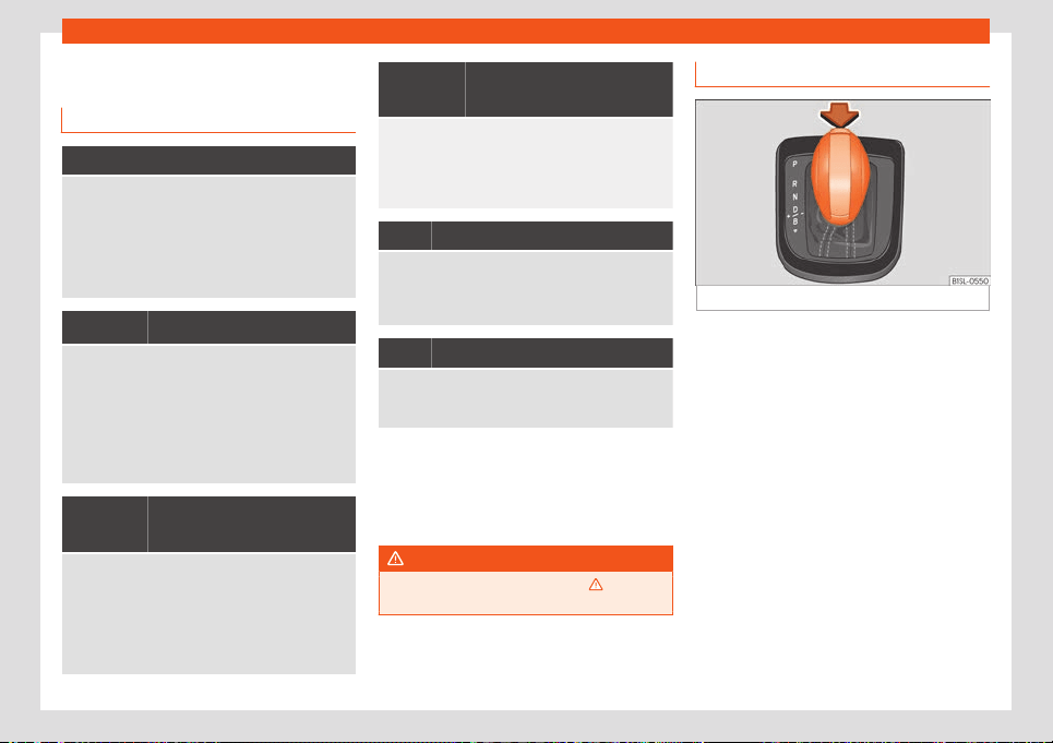
Driving
Gear selection
Contr
ol l
amps
It lights up red
There is a fault in the electrical system.
The instrument panel display shows the message
Error: Electr. Syst. Stop the vehi-
cle!
Stop the vehicle immediately as soon as it is
possible and safe, park it outdoors and disconnect
the drive system. Seek specialist assistance.
and
They light up red
The electrical system has overheated.
The instrument panel displ
ay shows the message
Electr. system overheated. Stop! Man-
ual!
Stop the vehicle immediately as soon as it is
possible and safe, park it outdoors and disconnect
the drive system. Do not pour coolant! Seek spe-
cialist assistance.
and
They light up yellow
Brake energy recuperation is not possible.
The instrument panel display shows the message
Error: Recuperation. Check the man-
ual.
Ther
e is a failure in the brake energy recuperation.
Autonomy may be limited. Contact a specialised
workshop.
and
They light up yellow
Limited braking capacity.
The instrument panel display shows the message
Error: Limited braking capacity.
The br
aking system does not work or has a fault.
Contact a specialised workshop.
It lights up green
The engine will not start.
The brake pedal is not pr
essed when changing the
position of the selector lever from N. To change the
position of the selector lever, press the brake pedal.
Flashes green
The lock button prevents starting to move.
The vehicle is pr
evented from moving forwards. The
selector lever locking button is not engaged.
Several warning and control lamps light up
f
or a f
e
w seconds when the ignition is switch-
ed on, signalling that the function is being
verified. They will switch off after a few sec-
onds.
WARNING
Observe the safety warnings
›››
in Con-
trol and warning l
amps on page 66.
Gear selector lever
Fig. 137
Gear selector lever
The vehicle has a forward gear D/B and a r
e-
v
erse gear
R.
The selector lever has a lock. To change the
selector lever from position P or N to another
position, switch on the ignition, press the
brake pedal and press the lock button on the
lever button in the direction of the arrow
›››
Fig. 137.
– Parking lock
The drive wheels are locked mechanically.
Select this position only when the vehicle is
stopped.
– Reverse gear
The reverse gear is engaged. Select this posi-
tion only when the vehicle is stopped.
140
Drive system and driving
- Neutr
al
The el
ectric driv
e system is in the neutral po-
sition. No movement is transmitted to the
wheels and the braking effect of the electric
engine does not occur.
– Permanent forward drive position
The electric drive system is in the normal pro-
gramme (brake energy recuperation levels
0-3).
– Very intense brake energy recupera-
tion
Very intense brake energy recuperation is de-
celeration phases (brake energy recupera-
tion level 4).
– Change between D and B
Changed between D and B by pushing the
selector lever gently backwards from position
D/B
›››
Fig. 137. The selector lever always re-
turns to D/B position. Pushing it gently back
again, it changes back to D.
Selector lever lock
In positions P and N, the selector lever lock
prevents the position selector lever from be-
ing changed by mistake and, as a conse-
quence, stops the vehicle from moving with-
out being desired.
To release the selector lever lock, press the
brake pedal and keep it pressed with the igni-
tion switched on. At the same time, press the
lock button on the selector lever.
If the selector lever is quickly changed from
position moving past N (i.e. from reverse gear
to D/B), the lever does not lock. This allows a
stuck vehicle to be “towed”, for example. If the
selector lever remains for more than approx. 1
second in position N without having the brake
pedal pressed or travelling at a speed below
about 5 km/h (3 mph), the lever locks.
In rare cases it may happen that the selector
lever lock does not engage. In this case, the
traction is cancelled to prevent the vehicle
from moving accidentally. To engage the se-
lector lever lock, proceed as follows:
●
Press the brake pedal and release it again.
●
OR: place the lever in the P or N position
and then select a gear.
WARNING
If the selector lever is placed in an inappro-
priate position, vehicl
e control could be
lost and an accident and serious injury
could result.
●
Never accelerate when changing the po-
sition lever.
●
Never engage reverse gear or parking
lock while the vehicle is in motion.
WARNING
Any accidental movement of the vehicle
could result in serious injury.
●
As a driv
er, never leave your seat when
the drive system is connected and a gear is
engaged. If you have to leave the vehicle
with the electric drive system connected,
always engage the handbrake and always
place the selector lever in position P.
●
Never leave the vehicle with the selector
lever in the N, R or D/B positions. The vehi-
cle could be set in motion depending on
the inclination of the road.
●
When the drive system is connected and
the selector lever is D/B o R position, the
vehicle must be stopped by pressing the
brake pedal.
●
Never engage reverse gear while the ve-
hicle is in motion.
CAUTION
●
If the vehicle is st
opped but the hand-
brake is not engaged and the brake pedal
is released with the selector lever in posi-
tion P, the vehicle can move a few centime-
tres forward or backward.
●
Never allow the vehicle to move with the
lever in the N position, especially when the
drive system is disconnected.
»
141
Driving
Note
If the selector lever is left for a long time in
a position other than P with the ignition off,
the 12-volt batt
ery may discharge.
Driving with an automatic gearbox
Driving down slopes
The steeper the slope
, the higher the selected
brake energy recuperation level will have to
be. A high recuperation level increases the
braking effect of the electric engine. Never let
the vehicle roll downhill with the selector lev-
er in the neutral position N.
●
You should reduce speed accordingly.
●
Set the selector lever to the B position.
Stop and star
t moving uphill
When the vehicle stops uphill with the forward
gear engaged, this will have to be avoided
whenever you go backwards by pressing the
brake pedal or engaging the handbrake. Do
not release the brake pedal or handbrake un-
til you start moving.
Kick-down
The kick-down function enables maximum
acceleration by pressing the accelerator
pedal fully with the selector lever in the D/B
position. In the Eco and Eco+ driving profiles,
the limitation of the maximum possible speed
is cancelled when the kick-down function is
used.
The vehicle does not move even though a
gear range is selected
If the vehicle does not move in the desired di-
rection, the system may not have recognised
the gear range correctly.
●
Press the brake pedal and select it again.
●
If the vehicle still does not move in the de-
sired direction, there is a fault in the system.
Request the help of specialised personnel
and have the system checked.
WARNING
Rapid acceleration can cause loss of trac-
tion and the vehicle skidding, especially on
slippery r
oads. This could cause loss of
control of the vehicle, accidents and seri-
ous injury.
●
Never press down hard or suddenly on
the acclerator pedal (kick-down) if the
conditions of visibility, weather, road and
traffic do not allow it, or if it endangers oth-
er users on the road due to the accelera-
tion of the vehicle and the driving style.
●
Always adapt the driving style to traffic
conditions.
●
When the ASR is disconnected, the drive
wheels may skid, especially if the road is
wet, slippery or dirty. This can cause the
vehicle to be neither steered nor control-
led.
WARNING
Never move the selector lever from position
P if the handbr
ake is not engaged. Other
-
wise, if the vehicle is on a slope, it could
start moving unexpectedly and cause an
accident and serious injuries.
CAUTION
●
When stopping uphill with a select
ed
gear range, do not step on the accelerator
to prevent the vehicle from moving back-
ward. Press the brake pedal to avoid un-
necessarily overloading the electric drive
system.
●
If the vehicle moves with the ignition and
electric drive system disconnected or with
the 12-volt battery discharged or without a
12-volt battery and the selector lever in the
N position for a prolonged period of time or
at a high speed, the electric drive system
will suffer damages.
142

Drive system and driving
Hill driving assistant
Ho
w it w
orks
The hill start assistant helps start moving up-
hill while keeping the v
ehicle actively
stopped.
The hill start assistant is automatically
connected if the following conditions are
met simultaneously:
●
The vehicle is stopped f
acing a hill by step-
ping on the brake pedal until the vehicle
starts moving.
●
The engine rotates correctly.
●
The gear range D is selected or the reverse
gear is engaged.
To start moving, remove your foot from the
brake pedal and accelerate immediately.
When starting to moving, the brake is re-
leased progressively.
The hill start assistant is immediately dis-
connected:
●
If any of the conditions mentioned above
ceases to be met.
●
If the driver door is opened.
●
If the electric drive system is disconnected.
●
If there is any failure in the electric drive
system.
●
The selector lever is in N position.
WARNING
●
If the vehicle does not st
art moving im-
mediately after releasing the brake pedal,
it could roll backwards under certain cir-
cumstances. In this case, immediately
press the brake pedal or engage the hand-
brake.
●
If the engine stops, immediately press the
brake pedal or engage the handbrake.
●
If, when driving uphill in heavy traffic, you
want to prevent the vehicle from rolling
backwards when you start moving, before
moving press the brake pedal for a few sec-
onds.
Steering
Inf
ormation r
el
ating to different ve-
hicle processes.
Electro-mechanical power steering assists
the driv
er when st
eering.
El
ectro-mechanical power steering adapts
electronically to the speed of the car, torque
and turning angle. The electromechanical
steering only work with the drive system con-
nected.
If the power steering does not work properly
or does not work at all, you will have to use
much more strength than usual to turn the
steering wheel.
Mechanical locking of the steering
To make it hard to steal the vehicle, always
lock the steering system before leaving it.
The steering column is locked by removing
the key from the ignition lock with the vehicle
stopped. Turn the steering wheel slightly until
the steering lock has engaged.
To release the steering lock, turn the steering
wheel slightly to reduce the pressure. Insert
the key in the ignition lock. Hold the steering
wheel in this position and switch on the igni-
tion.
WARNING
If the power steering does not work, you
have to use much mor
e strength to turn the
steering wheel and this can hinder the con-
trol of the vehicle.
●
The power steering only works with the
drive system connected.
●
Never allow the vehicle to move when the
drive system is disconnected.
●
Never remove the key from the ignition
lock when the vehicle is moving. The steer-
ing lock could suddenly become blocked
and it would be impossible to steer the ve-
hicle.
»
143
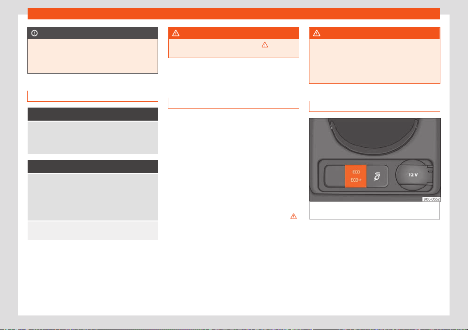
Driving
CAUTION
If the vehicle needs to be towed, leave the
ignition on so that the steering wheel is not
block
ed and the turn signals, the horn and
the windscreen wiper work.
Control lamp
It lights up red
Stop driving! The electromechanical steering is
fault
y.
Have the steering checked immediately by a special-
ised workshop.
It lights up yellow
The operation of the electromechanical steering is
limited.
Have the st
eering checked immediately by a special-
ised workshop. If the warning lamp does not come on
again after restarting the engine and driving a short
distance, it is not necessary to check the steering.
The 12-volt battery was disconnected and reconnec-
ted. Drive a short dist
ance at 15-20 km/h (9-12 mph).
Several warning and control lamps light up
f
or a f
e
w seconds when the ignition is switch-
ed on, signalling that the function is being
verified. They will switch off after a few sec-
onds.
WARNING
Observe the safety warnings
›››
in Con-
trol and warning l
amps on page 66.
Driving profiles
Introduction
By means of the driving profiles, the driver
can adapt different char
acteristics of the ve-
hicle systems to the current driving situation
and to an economic driving style. Among the
systems that can be adapted are, for exam-
ple, engine management and air condition-
ing.
The degree of influence of the vehicle config-
uration on the different driving profiles de-
pends on the vehicle’s equipment.
You can change the driving profile both with
the vehicle stopped and while in motion
›››
.
Aft
er sel
ecting a driving pr
ofile, the vehicle,
except the engine, is immediately configured
according to the new profile. When traffic
permits, briefly remove your foot from the ac-
celerator so that the selected driving profile is
also activated for the engine.
WARNING
Adjusting the driving profile while driving
can distract attention fr
om traffic and
cause accidents.
●
Always drive as carefully and responsibly
as possible.
Adjusting a driving profile
Fig. 138
In the lower part of the centre con-
sol
e: driving pr
ofil
e selection button.
Selecting a driving profile
●
Switch the ignition on.
●
To change the driving profile, press the driv-
ing pr
ofil
e sel
ect button
›››
Fig. 138 several
times.
When changing the driving profile, a message
is is displayed on the instrument panel dis-
play for a few seconds.
144
Drive system and driving
When
or profiles are selected, the
corr
esponding inscription
›
››
Fig. 138 remains
on in the selection button of the driving pro-
file.
Characteristics of driving profiles
This driving profile is always adjusted
when the drive system is connected. All
the power of the electric engine is avail-
able. The Climatronic works in normal
mode. When the Normal profile is selec-
ted, the Driving Mode Normal mes-
sage appears on the instrument panel
display.
In the ECO driving profile, the power of
the electric engine is limited to favour
lower energy consumption. The maxi-
mum speed is reduced. The Climatronic
switches to Eco mode, optimal for low
consumption, in which the fan and the
defrosting/demisting functions are still
available. When the ECO profile is selec-
ted, the Driving Mode Eco message
appears on the instrument panel dis-
play.
In the ECO+ driving profile, the power
of the electric engine is limited even
more to favour even lower energy con-
sumption. The maximum speed is re-
duced. The heating and cooling func-
tions of the Climatronic are disconnec-
ted; the fan and the defrosting/demisting
functions are still available. When the
Normal
ECO
ECO+
ECO+ profile is selected, the Driving
Mode Eco+ message appears on the in-
strument panel display.
WARNING
The driving properties may change de-
pending on the selected driving pr
ofile.
Never allow the selection of the driving pro-
file to induce you to take any risk that com-
promises safety.
●
Adapt your speed and driving style at all
times to suit visibility, weather, road and
traffic conditions.
Note
The power limitation of the electric engine
in the ECO and ECO+ driving profiles can
be cancell
ed temporarily by pressing the
accelerator pedal as far as it will go (“kick-
down”).
Driving tips
Running in
Running in new tyres and brake pads
●
Replacement of wheel rims and new tyres
›
›
›
page 187.
●
Information about brakes
›››
page 150.
Driving on flooded roads
To prevent damage to the vehicle driving on
flooded roads, t
ake the following into ac-
count:
●
The water should never come above the
lower edge of the bodywork.
●
Drive at pedestrian speed.
WARNING
After driving through flooded zones, brak-
ing effectiveness can decr
ease if the brake
discs or pads are damp
›››
page 150.
CAUTION
Driving through flooded areas may dam-
age vehicle components such as the driv
e
system, transmission or electrical system.
Note
●
Check the depth of the water bef
ore en-
tering the flooded zone.
●
Do not stop in the water, drive in reverse,
or stop the drive system.
●
Vehicles travelling in the opposite direc-
tion cause waves that could exceed your
vehicle's critical height.
●
Avoid driving through salt water (corro-
sion)
›››
page 196.
145
Driving
Trips abroad
In some countries, certain safety regulations
can be in force that diff
er from the vehicle's
technical characteristics. Before travelling
abroad, SEAT recommends you consult a
technical service about the legal require-
ments and the following points:
●
Does the vehicle need technical modifica-
tions for driving abroad, for example, adjust-
ment of the headlamps?
●
Does the vehicle have all the tools, diag-
nostics equipment and spare parts requir
ed
for inspections and repairs?
●
Are there any SEAT dealers in the destina-
tion country?
●
Will it be possible to find operating fluids
that meet SEAT specifications in the country
of destination?
●
Are special tyres required in the destination
country?
CAUTION
SEAT does not accept liability for any dam-
age to the vehicl
e due to an inadequate
service or the non-availability of genuine
spare parts.
Driver assistance systems
Cruise contr
ol syst
em
(CCS)*
Contr
ol lamp
It lights up green
The Cruise Control System (GRA) is switched on and
active.
The control lamps light up when the ignition is
s
wit
ched on and shoul
d turn off after approxi-
mately 2 seconds. This is the time taken for
the function check.
WARNING
Observe the safety warnings
›››
in Con-
trol and warning l
amps on page 66.
Introduction
The cruise control system (CCS) is able to
maint
ain the set speed fr
om 20 km/h (
15
mph).
The CSS only reduces vehicle speed by
ceasing to accelerate, not by actively braking
the vehicle
›››
.
Travelling down hills with the CCS
If the GRA cannot maint
ain a const
ant v
ehicle
speed downhill, brake and connect the brake
energy recuperation. The GRA is temporarily
disabled by pressing the brake.
Automatic off
The GRA disconnects automatically or is
temporarily interrupted:
●
If the system detects a fault that could af-
fect the working order of the CCS.
●
If you press and maintain the accelerator
pedal for a certain time, driving faster than
the stored speed.
●
If the dynamic driving control systems inter-
vene, ASR, ESC, etc.
●
If the brake pedal is pressed.
●
If the airbag is triggered.
●
If the lever is taken out of the D/B position.
●
If the emergency braking function in the city
brakes the vehicle.
WARNING
Use of GRA could cause accidents and se-
vere injuries if it is not possibl
e to drive at a
constant speed maintaining the safety dis-
tance.
●
Do not use GRA in heavy traffic, if the dis-
tance from the vehicle in front is insuffi-
cient, on steep roads, with several bends or
146
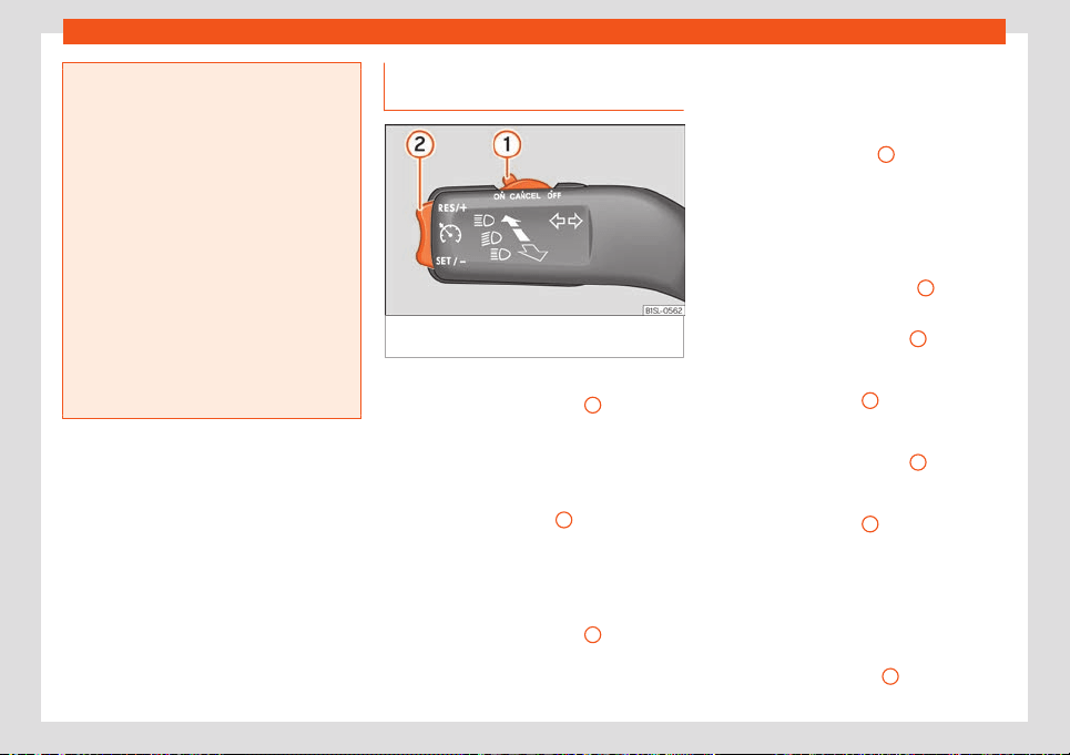
Driver assistance systems
in slippery circumstances or on flooded
roads.
●
Nev
er use the CCS when driving off-road
or on unpaved roads.
●
Adapt your speed and the distance to the
vehicles ahead in line with visibility, weath-
er, the condition of the road and the traffic
situation.
●
To avoid unexpected operation of the
cruise control system, turn it off every time
you finish using it.
●
It is dangerous to use a set speed which is
too high for other conditions.
●
If driving down a steep gradient, the GRA
cannot maintain a constant speed. The
speed can increase. In this case, reduce
the speed by braking or connecting the
brake energy recuperation.
Operating the cruise control with
the t
urn signal l
e
ver
Fig. 139
On the turn signal lever: controls for
oper
ating the GRA.
Connecting
●
Move the control
›
›
›
Fig. 139
1
to .
If no speed has been pr
ogr
ammed, the sys-
t
em will not control it.
Activating the cruise control
●
Press button
›››
Fig. 139
2
in area
.
The curr
ent speed is st
ored and the cruise
control is activated.
Temporarily interrupting
●
Move the control
›››
Fig. 139
1
to
or
st
ep on the brake.
The cruise control system is switched off tem-
porarily. The speed is stored.
Reinstating the cruise control
●
Press button
›››
Fig. 139
2
in area
.
Cruise contr
ol is activ
ated at the stored
speed.
Adjusting the speed
While the GRA is set, the stored speed can be
adjusted with button
›››
Fig. 139
2
:
●
To increase in increments of 1 km/h (1 mph)
briefly pr
ess butt
on
›
››
Fig. 139
2
in the area
.
●
To increase the speed without interruption,
keep button
›››
Fig. 139
2
pressed down in
the ar
ea
.
●
To reduce in increments of 1 km/h (1 mph)
briefly press button
›››
Fig. 139
2
in the area
.
●
To reduce the speed without interruption,
k
eep butt
on
›
››
Fig. 139
2
pressed down in
the ar
ea .
The v
ehicl
e adapts the current speed by ac-
celerating or stopping accelerating. The vehi-
cle does not brake actively.
Switching off
●
Move control
›››
Fig. 139
1
to .
»
147
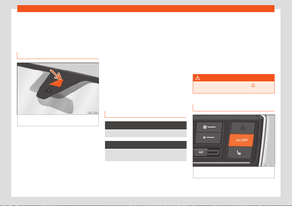
Driving
The system is disconnected and the memo-
rised speed is del
et
ed.
L
ane Assist*
Introduction
Fig. 140 On the windscreen: field of vision of
the L
ane Assist syst
em.
The Lane Assist System helps the driver stay
in their l
ane
. This function is not suit
able and
is not designed to keep the vehicle automati-
cally in the lane.
Using the camera located in the windscreen,
the Lane Assist system detects the possible
lines dividing the lanes. When the vehicle in-
voluntarily approaches a dividing line it has
detected, the system notifies the driver with a
corrective steering movement. This move-
ment can be over-regulated at any time.
No warning is produced with the turn signals
activated, given that the Lane Assist system
understands that a lane change is required.
System limits
Use the Lane Assist system only on large,
well-maintained motorways and highways.
The system is not available under the follow-
ing conditions:
●
The driving speed allowed is below 55 km/h
(32 mph).
●
The system has not detected any lane
lines.
●
Temporarily in very sporty driving situations.
Control lamp
It lights up green
Lane Assist system active and available.
It lights up yellow
The Lane Assist system intervening with a rectifica-
tion of the steering.
If the corresponding warning lamp does not
light up on the instrument clust
er
, this can
mean that:
●
The minimum speed has not been r
eached.
●
The system does not recognise the lane
lines.
●
Or the system is not available.
If the latter persists, go to a specialised work-
shop to repair the fault.
Some control and warning lamps will light up
briefly when the ignition is switched on to
check certain functions. They will switch off
after a few seconds.
WARNING
Observe the safety warnings
›››
in Con-
trol and warning l
amps on page 66.
Operating mode
Fig. 141 In the centre console: button to con-
nect the l
ane assist syst
em
148
Driver assistance systems
Connecting and disconnecting the lane
assist syst
em
The l
ane assist syst
em is always activated
when the ignition is switched on. Pressing the
button
›››
Fig. 141 enables to deacti-
vate the assist system until the next time the
engine is started.
The button
›››
Fig. 141 is backlit if the
system has been disconnected or has a fault.
The Lane Assist system can actively intervene
as of approximately 60 km/h (35 mph) if it
has detected lane lines.
If the control lamp of the instrument panel
display is off, it means that the assist system
is connected but not ready to adjust steering
(system in passive state) or disconnected.
When you activate a turn signal, the system
temporarily goes into a passive state in order
to allow manual lane change.
Driver intervention prompt
If the steering is not corrected manually, the
system prompts the driver through an indica-
tion on the instrument panel display and
acoustic warnings to actively take the steer-
ing wheel.
If no reaction is obtained from the driver, the
system switches to a passive state.
Through an indication on the instrument pan-
el display and acoustic warnings, the driver is
also prompted to drive through the centre of
the lane if the steering correction lasts more
than reasonable.
Steering wheel vibration
If the system stops displaying the lane lines
while assisting with steering, it can cause the
steering wheel to vibrate. This situation re-
quires the driver to actively assume control.
Switching off the Lane Assist system in the
following situations
Due to the limits of the Lane Assist system,
switch it off in the following situations:
●
When more attention is required of the driv-
er
●
When driving in a sporty style
●
In unfavourable weather conditions
●
On roads in poor condition
●
In areas of road works
WARNING
The intelligent technology in the Lane As-
sist system cannot change the limits im-
posed by the laws of physics and by the
v
ery nature of the system. Careless or un-
controlled use of the Lane Assist system
may cause accidents and injury. The sys-
tem is not a replacement for driver aware-
ness.
●
Always adapt your speed and the dis-
t
ance to the vehicles ahead in line with visi-
bility, weather conditions, the condition of
the road and the traffic situation.
●
Always keep your hands on the steering
wheel so it can be turned at any time.
●
The Lane Assist system does not detect
all road markings. The road surfaces, road
structures or objects in poor condition can
be incorrectly detected as road markings
under certain circumstances by the Lane
Assist system. In such situations, switch the
Lane Assist system off immediately.
●
Please observe the indications on the in-
strument panel and act as is necessary.
●
In the following situations there may be
counter-productive interventions of the
system or it may be that the system does
not intervene at all. In these situations, spe-
cial attention is required from the driver
and, where appropriate, the temporary de-
activation of the lane assist warning sys-
tem:
–
In very sporty driving situations.
–
In adverse weather conditions and
roads in poor condition.
–
When passing through areas undergo-
ing works.
–
Before gradient changes of grade and
river beds.
●
Always pay attention to the vehicle's sur-
roundings.
»
149
Driving
●
When the area of vision of the camera
becomes dir
ty, covered or is damaged, the
Lane Assist system function can be affec-
ted.
CAUTION
In order to avoid influencing the operation
of the syst
em, the foll
owing points must be
taken into account:
●
Regularly clean the area of vision of the
camera and keep it in a clean state, without
snow or ice
›››
Fig. 140.
●
Do not cover the area of vision of the
camera.
●
Check that the area of vision of the wind-
screen camera is not damaged.
Note
●
The Lane Assist system can be aut
omati-
cally disconnected if it registers a fault.
●
The lane departure warning system has
been exclusively developed for driving on
paved roads only.
●
If the Lane Assist system does not work as
described in this chapter, do not use it and
contact a specialised workshop.
●
If there is a fault in the system, have it
checked by a specialised workshop.
Braking and parking
Br
aking syst
em
Contr
ol lamps
It lights up red
Brake fluid level is too low
›››
page 180; or, failure in
the braking system.
Do not carry on driving!
It lights up red
Handbrake applied
›››
page 152.
The warning lamp turns off when the handbrake is re-
leased.
WARNING
●
If the brake w
arning lamp does not go
out or if it lights up when driving, the brake
fluid level in the reservoir is too lo so there
is a risk of an accident
›››
page 180, Brake
fluid. Stop the vehicle and do not drive on.
Obtain technical assistance.
●
If the brake warning lamp lights up to-
gether with the ABS lamp this could be
due to an ABS fault. When this function
fails, the rear wheels can lock up. Under
certain circumstances, the rear of the vehi-
cle may skid, with the danger of losing con-
trol. Stop and seek technical assistance.
Information about the brakes
New brake pads
For the first 200 to 300 km (
100 to 200
miles), new brake pads have not yet reached
their maximum braking capacity, and need to
be “run in” first. However, you can compen-
sate for the slightly reduced braking effect by
applying more pressure on the brake pedal.
Avoid overloading the brakes while running
them in.
Wear
The rate of wear on the brake pads depends
a great deal on how you drive and the condi-
tions in which the vehicle is operated. This is a
particular problem in urban traffic and short
stretches, or with very sporty driving.
Depending on the speed, the braking force
and the environmental conditions (e.g. tem-
perature, air humidity, etc.) noises may be
produced when braking.
Wet roads or road salt
In certain situations (for example, on driving
through flooded areas, in severe downpours
or after washing the vehicle) the braking ac-
tion could be delayed if the discs and pads
are damp, or frozen in winter. In this case the
brakes should be “dried” by pressing the
brake pedal several times.
150
Braking and parking
At high speed and with the windscreen wipers
activ
at
ed, the br
ake pads will briefly touch
the brake discs. This takes place, although
unnoticeable to the driver, at regular intervals
to improve the response time of the brakes
when they are wet.
The effectiveness of the brakes can also be
temporarily reduced if the vehicle is driven for
some distance without using the brakes when
there is a lot of salt on the road in winter. The
layer of salt that accumulates on the discs
and pads can be removed by gently apply-
ing the brakes a few times.
Corrosion
There may be a tendency for corrosion to
form on the discs and dirt to build up on the
brake pads if the vehicle is used infrequently
or the brakes are not used very often.
If the brakes are not used frequently, or if rust
has formed on the disks, it is advisable to
clean off the pads and disks by braking firmly
a few times at a moderately high speed
›››
.
F
ault in the br
ak
e system
If the brake pedal travel should ever increase
suddenly, this may mean that one of the two
brake circuits has failed. Drive immediately to
the nearest specialised workshop and have
the fault repaired. Drive there slowly and re-
member that you will have to apply more
pressure on the brake pedal and allow for
longer stopping distances.
Low brake fluid level
Malfunctions can occur in the brake system if
the brake fluid level is too low. The brake fluid
level is monitored electronically.
Brake servo
The electromechanical brake servo increases
the pressure that you exert when you press
the brake pedal. It only works when the vehi-
cle’s ignition or drive system is switched on.
WARNING
Any anomaly in the brake system can in-
crease the braking dist
ance, with the re-
sulting risk of an accident.
●
New brake pads and discs must be run in
and do not have the correct friction during
the first 200 km (124 miles). This reduced
braking capacity may be offset by pressing
on the brake pedal a little harder.
●
If you are driving on roads which have
been salted, braking effectiveness may be
decreased.
●
Brakes can overheat if used excessively
on slopes. Before descending a long, steep
gradient, slow down and select a higher re-
cuperation level
›››
page 134. Therefore, us-
ing the engine brake relieves the brakes.
●
Gentle continuous braking causes the
br
akes to overheat and the braking dis-
tance will increase. Apply and then release
the brakes alternately.
●
Apply the brakes heavily to clean the
brake system only in a suitable traffic situa-
tion. Do not put other road users in danger:
there is risk of causing an accident.
●
Ensure the vehicle does not move while in
neutral, when the engine is stopped. The
braking distance is increased considerably
when the brake servo is not active.
●
If the brake is subjected to high stresses,
vapour bubbles may form in the brake sys-
tem's pipes. This reduces the efficiency of
the brakes.
●
Non-standard or damaged front spoilers
could restrict the airflow to the brakes and
cause them to overheat. Before purchasing
accessories please read the relevant in-
structions.
CAUTION
●
Never l
et the brakes “drag” by leaving
your foot on the pedal when it is not neces-
sary to brake. This overheats the brakes, re-
sulting in longer stopping distances and
greater wear.
●
Before descending a long, steep gradi-
ent, we recommend slowing down and se-
lecting a higher recuperation level
›››
page 134. This makes use of engine brak-
ing and relieves the brakes. If you still have
»
151
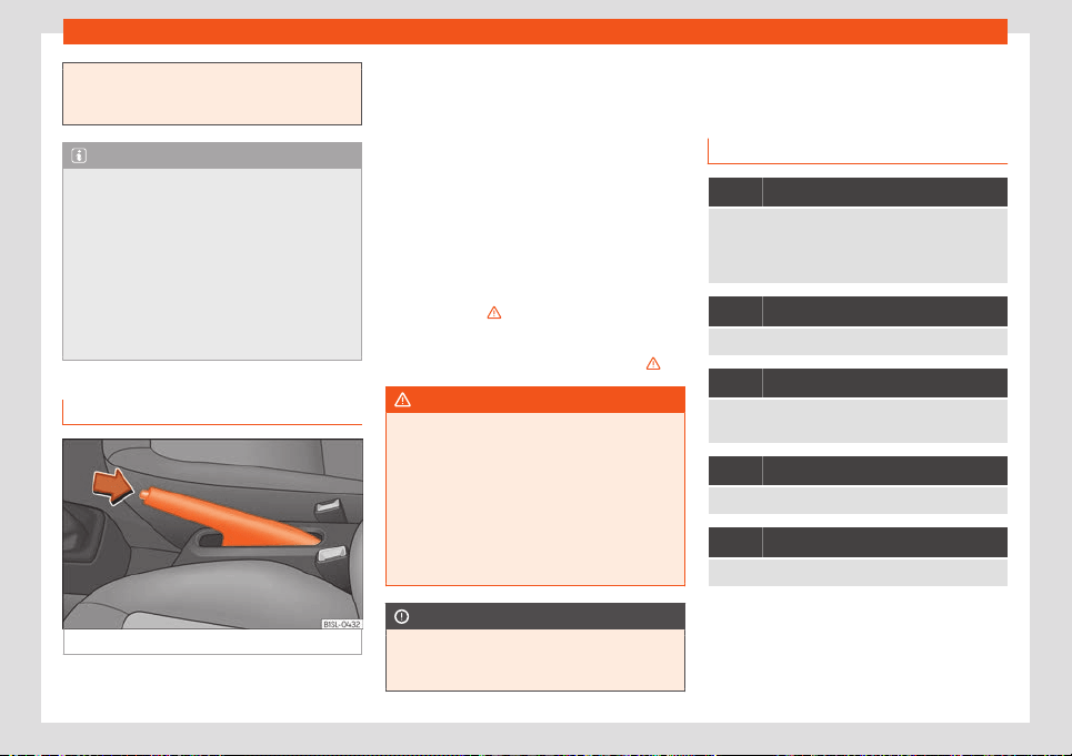
Driving
to use the brakes, it is better to brake firmly
at interval
s than to apply the brakes con-
tinuously.
Note
●
If the br
ake serv
o is out of action, for ex-
ample when the car is being towed, you will
have to press the brake pedal considerably
harder than normal to make up for the lack
of servo assistance.
●
If you wish to equip the vehicle with ac-
cessories such as a front spoiler or wheel
covers, it is important that the flow of air to
the front wheels is not obstructed, other-
wise the brakes can overheat.
Handbrake
Fig. 142 Handbrake between the front seats.
The handbrake should be applied firmly to
pr
e
v
ent the vehicle from accidentally moving.
Apply the handbrake when you leave your
vehicle and when you park.
Applying the handbrake
–
Pull the handbrake lever up
›››
Fig. 142. The
handbrake is set when the control lamp
lights up.
Releasing the handbrake
–
Pull the lever up slightly and press the re-
lease knob in the direction of the arrow
›››
Fig. 142 and guide the handbrake lever
down fully
›››
.
Al
w
ays pull the handbr
ake all the way up, to
avoid driving off while the brake is on
›››
.
WARNING
●
Never use the handbr
ake to stop the vehi-
cle when it is in motion. The braking dis-
tance is considerably longer, because
braking is only applied to the rear wheels.
Risk of accident!
●
Failure to fully lower the handbrake lever
can affect the operation of the system, and
can also cause heating and wear of the
rear brakes.
CAUTION
Do not forget to apply the handbrake
whenever you l
eave the vehicle, and put
the selector lever in the P position.
Stabilisation and brake as-
sist
ance syst
ems
Contr
ol lamps
It lights up
Fault in the ESC or ABS, or disconnection caused by
the system.
The ESC works in combination with the ABS. If the
ABS fails, the lamp also lights up.
Flashes
ESC or ASR activated.
It lights up
Fault in the ASR or disconnection caused by the sys-
tem.
Flashes
ASR working.
It lights up
ABS faulty or does not work.
The control lamps light up together when the
ignition is s
wit
ched on and shoul
d turn off af-
ter approximately 2 seconds. This is the time
taken for the function check.
152

Braking and parking
WARNING
Observe the safety warnings
›››
in Con-
trol and warning l
amps on page 66.
Brake assist systems
Electronic Stability Control (ESC)*
The ESC helps to impro
ve safety. It reduces
the tendency to skid and improves the stabili-
ty and roadholding of the vehicle. The ESC
detects critical handling situations, such as
vehicle understeer or oversteer, or wheelspin
on the driving wheels. It stabilises the vehicle
by braking individual wheels or by reducing
the engine torque. The warning lamp will
flash on the instrument panel when the ESC is
intervening .
The ESC includes the anti-lock brake system
(ABS), the hydraulic brake assist (HBA), the
traction control system (ASR) and the elec-
tronic differential lock (EDS)
ESC also helps stabilise the vehicle by
changing the torque.
Anti-lock brake system (ABS)
ABS prevents the wheels from locking up un-
der braking until the vehicle has reached a
virtual standstill. You can continue to steer the
vehicle even when the brakes are on full.
Keep your foot on the brake pedal and do not
pump the brakes. You will feel the brake pedal
pulsate whil
e the ABS is working.
If the running gear or brake system is modi-
fied, the effectiveness of the ABS could be se-
verely limited.
Hydraulic Brake Assist (HBA)*
The brake assist system can reduce the re-
quired braking distance. The braking force is
automatically boosted if you press the brake
pedal quickly in an emergency. You must
keep pressing the brake pedal until the dan-
ger has passed.
Traction control system (ASR)
In the event of wheelspin, the traction control
system reduces the engine torque to match
the amount of grip available. This helps the
car to start moving, accelerate or climb a
gradient.
Electronic differential lock (EDL)*
When the EDL detects wheelspin, it brakes
the spinning wheel and directs the power to
the other driven wheel. This function is active
up to approximately 100 km/h (62 mph).
To prevent the disc brake of the braked wheel
from overheating, the EDL cuts out automati-
cally if subjected to excessive loads. The ve-
hicle can still be driven. The EDL will switch on
again automatically when the brake has
cooled down.
Electronic brake pressure distribution
(EBV)
In all vehicles, when the brakes are applied,
the centre of gravity of the vehicle moves for-
ward. As a consequence, there is a danger
that the rear wheels may lock due to their low
traction. The electronic brake pressure distri-
bution controls the brake pressure for the rear
wheels and ensures that this pressure is dis-
tributed optimally between the front and rear
axles. Under normal circumstances it pre-
vents the rear part of the vehicle from skid-
ding due to excessive braking of the rear
wheels. The function of the electronic brake
pressure distribution is incorporated in the
ABS function.
Electromechanical brake servo (eBKV)
With the ignition switched on, the electrome-
chanical brake servo supports the force of
the foot by increasing the pressure that the
driver exerts on the brake pedal. After discon-
necting the ignition, the assistance of the
brake servo is progressively reduced. Once
stopped, immobilise the vehicle to prevent it
from moving
›››
page 154.
If the electromechanical brake servo does
not work, the yellow control lamps and
on the instrument panel display light up at
the same time. When braking with the faulty
electromechanical brake servo, vibration of
the brake pedal may occur.
»
153
Driving
If the electromechanical brake servo is not
w
orking, the br
ak
e pedal must be pressed
harder, as the braking distance increases due
to the lack of assistance from the servo brake.
Brake blending
The brake energy recuperation can generate
a braking effect
›››
page 134. This braking ef-
fect depends on the selected driving pro-
gramme and the level of charge of the high-
voltage battery. If the braking effect caused
by the recuperation is very intense, the vehi-
cle’s brake lights with turn on. The electric en-
gine, when operating as an alternator, can
generate braking torque on the front wheels
based on the RPM and the temperature and
charge level of the high-voltage battery.
These variable parameters cause fluctuating
electric decelerations which are hydraulical-
ly compensated according to the driver’s de-
sires. This function is called “brake blending”
and it combines mechanical braking with the
engine brake effect.
WARNING
Driving at high speed on icy, slippery wet
ground can result in l
oss of vehicle control
and serious injury to the driver and passen-
gers.
●
The ESC, ABS, ASR, EDS or HBA systems
are neither in conditions to exceed the lim-
its established by the laws of physics. Al-
ways bear this in mind, especially on wet or
slippery roads. If you notice the systems
cutting in, you should reduce your speed
immediat
ely to suit the road and traffic
conditions. Do not be encouraged to take
risks by the presence of more safety sys-
tems. If you do, an accident may occur.
●
Please remember that the accident risk
always increases if you drive fast, espe-
cially in corners or on a slippery road, or if
you follow too close behind the vehicle in
front of you. The ESC, ABS, ASR, EDS or HBA
system cannot prevent accidents from oc-
curing: risk of accidents!
●
Accelerate with caution on slippery sur-
faces (for example, icy or snow-covered).
Despite the control systems, the driven
wheels could spin, affecting the stability of
the vehicle: risk of accident!
Note
●
The ABS and ASR will only operate cor
-
rectly if the four wheels have identical
tyres. Any differences in the rolling radius
of the tyres can cause the system to re-
duce engine power when this is not desired.
●
The regulating processes of the systems
can make noises due to their operation.
●
If the warning lamp or lights up,
there could be a fault
›››
page 65.
●
Any modifications made to the vehicle
(for example, to the engine, brake system,
running gear or to the combination of
wheels and tyres) may affect the operation
of the ABS, ASR and EDS.
Parking
To park the vehicl
e
When parking your vehicle, all legal require-
ments should be observed.
Al
ways note the following points when park-
ing the vehicle:
●
Park the vehicle on a suitable surface
›››
.
●
Apply the handbrake
›
›
›
page 152.
●
Set the selector lever to the P position.
●
Connect the drive system.
●
Turn the steering wheel slightly to engage
the steering lock.
●
When leaving the vehicle, take all keys with
you.
Additionally, on steep slopes and inclines
Before switching off the engine, rotate the
steering wheel so that if the vehicle should
move, it will be held by the kerb.
●
On slopes, turn the front wheels so that
they are against the edge of the kerb.
●
Uphill, turn the wheels towards the centre of
the road.
154
Help with parking and manoeuvring
WARNING
●
Avoid parking the vehicl
e where the hot
exhaust system could ignite inflammable
materials, such as dry grass, low bushes,
spilt fuel or flammable materials.
●
Do not leave passengers inside a closed
vehicle, they may not be able to open
doors or windows. Locked doors hinder the
possibility of a rescue.
●
Children should not be left alone in the
vehicle. They could tamper with the hand-
brake or the gears, which could cause the
vehicle to move without control.
●
Depending on weather conditions, it may
become extremely hot or cold inside the
vehicle. This can be fatal.
Help with parking and ma-
noeuvring
P
arking dist
ance w
arning
system*
Introduction
The parking distance warning system assists
the driver when parking. If the rear of the v
e-
hicle is approaching an obstacle, an intermit-
tent audible warning is emitted. The shorter
the distance, the shorter the intervals be-
tween tones. If the vehicle is too close to the
obstacle, the audible warning becomes con-
stant.
If you continue to approach an obstacle
when the sound is continuous, this means the
system can no longer measure the distance.
Sensors situated on the rear bumper transmit
and receive ultrasound. Using the ultrasound
signal (transmission, reflection from the ob-
stacles and reception), this system continu-
ously calculates the distance between the
bumper and the obstacle.
WARNING
The parking distance warning system can-
not replace the driv
er's assessment of the
situation.
●
The sensors have blind spots in which ob-
stacl
es and people are not registered.
●
Always observe the area around the vehi-
cle, as the sensors do not always detect
small children, animals or objects.
●
The surface of certain objects and some
clothing do not reflect the ultrasound sig-
nals from the parking distance system. The
system cannot detect or incorrectly de-
tects these objects and people wearing
these types of clothes.
●
External sound sources can affect the
parking distance aid signals. In this case,
under certain circumstances, people and
objects will not be detected.
CAUTION
●
The sensors may not always be abl
e to
detect objects such as trailer draw bars,
thin rails, fences, posts, trees and open
boots, etc. This could result in damage to
your car.
●
Although the parking distance warning
system detects and warns of the presence
of an obstacle, the obstacle could disap-
pear from the angle of measurement of the
sensors if it is too high or low and the sys-
tem would no longer show it. Therefore, it
will not warn you of these objects. Ignoring
the warnings of the parking sensor system
could cause considerable damage to the
vehicle.
»
155
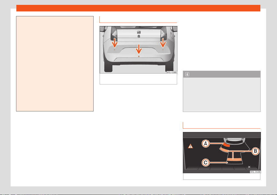
Driving
●
The bumper sensors may become dam-
aged or misaligned, for ex
ample, when
parking.
●
To ensure that the system works properly,
the bumper sensors must be kept clean,
free of ice and snow and uncovered.
●
When cleaning the sensors with high-
pressure or steam cleaning equipment,
spray the sensors briefly at a distance of
no less than 10 cm.
●
Different sources of noise can produce
errors in the parking distance warning sys-
tem, e.g. parking distance warning systems
from other vehicles, inductive loops or con-
struction works machines.
●
Retrofitting of components to the vehicle,
such as a bicycle carrier, may interfere with
the function of the parking distance warn-
ing system.
Parking distance warning system
Fig. 143
Parking distance warning system sen-
sors on the r
ear bumper
The sensors of the parking distance warning
syst
em ar
e sit
uated on the rear bumper
›››
Fig. 143.
Switching the parking distance warning
system on and off
●
Switch on: With the ignition switched on, se-
lect reverse gear. A short audible warning
confirms that the parking distance warning
system is switched on and functioning.
●
Switch off: Release reverse gear.
Special features of the parking distance
warning system
●
The parking distance warning system
sometimes registers water on the sensors as
an obstacle.
●
If the distance does not change, the warn-
ing signal will sound less loudly after a few
seconds. If the continuous signal sounds, the
volume will remain constant.
●
When the vehicle moves away from the ob-
stacle, the beeping sound automatically
switches off. When getting close again, it re-
connects.
●
Your SEAT dealership can adjust the volume
of the warning signals.
Note
A fault in the parking distance warning sys-
tem is indicated thr
ough a brief audible
warning that is constant for about 3 sec-
onds when switching it on the first time.
Have the parking distance warning system
checked as soon as possible at a special-
ised workshop.
Optical parking system* (OPS)
Fig. 144 On-screen OPS display
156
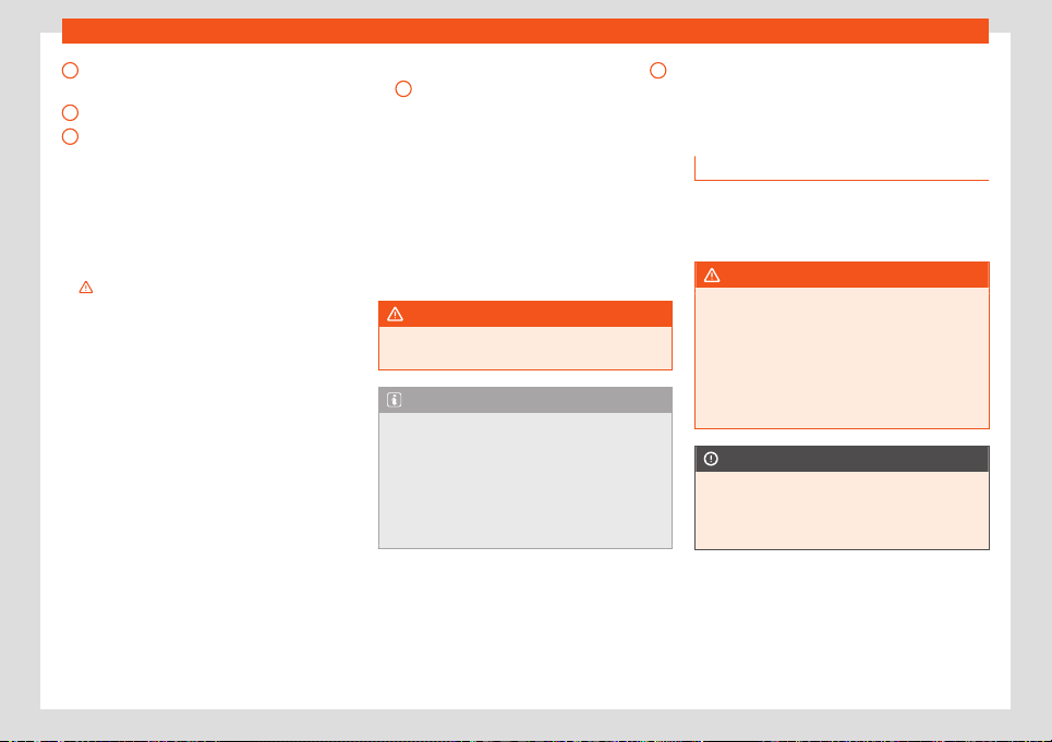
Towing bracket device
An obstacle was detected in the collision
ar
ea
An obst
acl
e was detected in the segment
Zone behind the vehicle registered
The optical parking system is an extension of
the parking distance warning system
›››
page 156.
The radio screen displays the area behind
the vehicle recorded by the sensors. Any ob-
stacles are displayed in relation to the vehicle
›››
.
Connect the indication
●
Activate the parking distance warning sys-
t
em
›
›
›
page 156. The OPS switches on auto-
matically.
Manually disconnect the indication
●
Remove reverse gear.
Zones explored
The approximate measurement range of the
sensors is:
1.50 m
0.60 m
Screen display
The image displayed represents the super-
vised zones in several segments. As the vehi-
cle approaches an obstacle, it approaches
A
B
C
Rear area:
Rear side area:
the displayed vehicle segment
›
›
›
Fig. 144
A
or
B
. Ultimately, when the second-to-last
segment is sho
wn, the collision ar
ea has been
r
eached. Stop the vehicle!
Segment colours (colour display)
The distance to the obstacle behind is
approximately 31-150 cm. The audio
signal is intermittent.
The distance to the obstacle behind is
approximately 0-30 cm. The audio sig-
nal is continuous.
WARNING
Do not be distracted from traffic to look at
the display.
Note
●
SEAT recommends practising using the
parking dist
ance warning system in a traf-
fic-free zone or in a car park to familiarise
yourself with the system and its operation.
●
The display on the radio display of the
area explored by the sensors may take up
to 5 seconds.
Yellow
Red
Towing bracket device
T
r
ail
er mode
Information on driving with a trailer
The vehicle is not certified for trail
er coupling.
The vehicle is not factory-equipped with a
towing bracket, nor is it possible to retrofit it.
WARNING
Installing a towing bracket on the vehicle
may cause accidents and serious injuries
while operating the v
ehicle.
●
Never install a towing bracket on the ve-
hicle.
●
The trailer may be released from the ve-
hicle when the vehicle is moving.
CAUTION
Any type of towing bracket installed on the
vehicle can cause serious and costly dam-
age that ar
e not covered under the SEAT
guarantee.
157
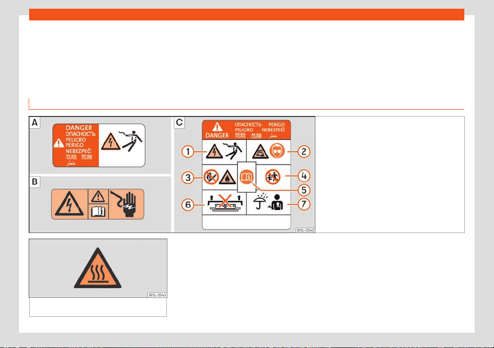
Practical tips
Practical tips
High-v
olt
age batt
ery
Safety warnings relating to the high-voltage network and the high-voltage battery
Introduction
Fig. 145 Warning signs (schematic representa-
tions): High-voltage components.
General
high-voltage warning sign. High-voltage battery
warning sign.
Fig. 146 When charging, in the engine com-
partment: hot surface warning.
Overview of the high-voltage system
The high-v
olt
age syst
em is made up by,
among others, the following components:
●
High-voltage battery
●
Electronic power module
●
Electric engine
●
High-voltage air conditioning compressor
●
High-voltage battery charger
●
High-voltage battery charging socket
●
Orange coloured high-voltage cables and
connectors
●
High-voltage heater
The works that are to be carried out on the
high-voltage system should be performed ex-
clusively by a specialised workshop with duly
158
High-voltage battery
qualified technical staff, trained according to
the SEAT guidelines
›
›
›
page 174 .
Handling the warning signs and stickers
›››
page 205.
General high-voltage warning signs
The high-voltage warning signs
›››
Fig. 145
and warn of the existence of high electrical
voltage
›››
. The following vehicle parts may
come with these w
arning signs:
●
The co
v
ers and lids behind which there are
high-voltage components under high-volt-
age.
●
All the high-voltage components, including
the high-voltage battery.
●
The lock carrier, in the engine compart-
ment.
High-voltage battery warning sign
The high-voltage battery comes with a sign
that warns of its hazards.
Key to
›››
Fig. 145
High-voltage can cause serious injuries or
even death. Never touch the battery
poles with bare fingers, tools, jewellery or
other metal objects.
The high-voltage battery contains haz-
ardous liquid and solid substances. In the
event of gases emitting from the battery,
these could cause serious burns and
1
2
blindness. When performing works on
high-v
olt
age batt
ery, always use appro-
priate eye protection and and protective
clothing to avoid skin and eyes from com-
ing into contact with the battery fluid. If
the battery fluid were to come into con-
tact with skin or eyes, immediately rinse
the affected area with clean water for at
least 15 minutes and seek medical assis-
tance.
The high-voltage battery may burn. Nev-
er expose the high-voltage battery to
sources of fire, sparks or unprotected
flames. Always handle the high-voltage
battery with care to avoid damaging it
and, consequently, fluid from leaking.
Always keep children away from from the
high-voltage battery.
The instruction manual and the workshop
information contain further information
and warnings to this regard.
An inappropriate handling of the high-
voltage battery can cause serious injuries
or death. Never remove the cover from
the high-voltage battery and never re-
move the high-voltage battery.
An inappropriate handling of the high-
voltage battery can cause serious injuries
or death. All maintenance works involving
the high-voltage battery should only be
performed by duly qualified and trained
technical staff . Never modify the high-
voltage battery in any way. When the
3
4
5
6
7
high-voltage battery is open, ensure it
does not come int
o cont
act with w
ater or
other liquids. Liquids may cause short cir-
cuits, electrical shocks and burns.
WARNING
The vehicle’s high-voltage network and the
high-voltage batt
ery are hazardous and
can cause burns, other injuries and an
electrical shock with deathly consequen-
ces.
●
Always consider that the high-voltage
battery is fully charged and that all the
high-voltage components are powered.
This may may be the case even with the
electric drive system and the ignition dis-
connected.
●
Never touch the high-voltage cables or
the high-voltage battery and its poles, and
never touch them with jewellery or other
metal objects, especially when the cables,
battery and its poles are damaged.
●
Never take it upon yourself to perform
any type of work on the high-voltage net-
work, on the high-voltage cables or the
high-voltage battery.
●
Never open the components or parts of
the high-voltage network. Never perform
any maintenance work on these elements,
nor repair or uncouple the high-voltage
network.
●
Never damage, modify or remove the or-
ange coloured high-voltage cables, and
»
159
Practical tips
never uncouple them from the high-voltage
network.
●
Ne
ver open, modify or remove the cover
from the high-voltage battery.
●
Only duly qualified and trained techni-
cians are authorised to perform works on
the high-voltage system and on any other
systems on which these may have indirect
influence.
●
To perform works close to high-voltage
components and cables which require the
use of sharp tools, which may deform or re-
lease shavings, or sources of heat, such as
works involving welding, soldering, use of
hot air or thermal gluing, you must first en-
sure the system is not powered. Only duly
qualified and trained technicians are au-
thorised to leave the high-voltage system
without power.
●
When performing any work on the high-
voltage system and the high-voltage bat-
tery, ensure you bear in mind the SEAT
guidelines and standards.
●
Keep the vehicle key in a safe place at a
safe distance from the vehicle to prevent
the ignition from turning on by mistake.
●
The gases that are released or leaked
from the high-voltage battery may be toxic
or flammable.
●
Any damage caused to the vehicle or the
high-voltage battery may lead to an imme-
diate or subsequent leak of toxic gases.
These gases can also cause a fire. In the
event of any damage, always open the ve-
hicle windows so the gases can fl
ow out of
the vehicle. Do not inhale the gases.
●
Never touch the fluids or come into con-
tact with the gases that may be released
from the high-voltage battery, especially if
the battery has been damaged.
●
In the event of a fire, leave the danger
area and call the fire department. Inform
the fire fighters that the vehicle is fitted
with an electric drive system.
●
Always inform the emergency service
that the vehicle is fitted with a high-voltage
battery.
WARNING
If works are performed on the high-voltage
system and on the high-volt
age compo-
nents in an inappropriate manner, this may
lead to faults in the operation, accidents
and injuries.
●
Only duly qualified and trained techni-
cians are authorised to perform works on
the high-voltage system and on any other
systems on which these may have indirect
influence.
WARNING
Electric vehicles do not make any noise
when the vehicle is not mo
ving and very lit-
tle noise when the vehicle is moving. Hence
other road users, such as pedestrians or
children, cannot hear or perceive their
presence, or they do so with difficult
y. This
may lead to accidents and cause injuries,
for example, in residential areas, when ma-
noeuvring or moving in reverse gear.
CAUTION
After an accident or having hit an obstacle
with the v
ehicle underside
, the high-volt-
age battery must be checked by duly
qualified and trained technicians.
Charging the high-voltage
batt
ery
Contr
ol l
amps
Its lights up yellow. The charge
lev
el display needle is in the area
marked in red.
The high-voltage battery charge has reached the re-
serve le
vel.
Charge the high-voltage battery.
160
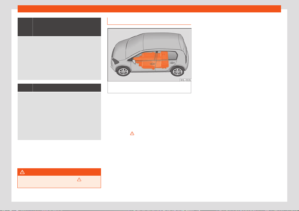
High-voltage battery
Its lights up yellow. A text mes-
sage will also appear on the in-
strument panel display.
The
Eco or Eco+ driving profile will be activ
e. The
power is reduced and certain consumers are auto-
matically switched off, such as the air conditioning
system. The vehicle may already be travelling in re-
serve mode.
The high-voltage battery charge has reached the re-
serve level. The vehicle autonomy will only be of a
few kilometres.
Charge the high-voltage battery immediately.
Its lights up yellow.
The power is reduced and there is very little autono-
my.
A text message will al
so appear on the instrument
panel display.
The maximum speed is limited to 80 km/h (50 mph).
The Eco+ driving profile will be active.
The high-voltage battery is discharged. There is only
sufficient autonomy for a few hundred metres. Stop
the vehicle in a safe place. Charge the high-voltage
battery immediately.
The control lamps light up together when the
ignition is s
wit
ched on and shoul
d turn off af-
ter approximately 2 seconds. This is the time
taken for the function check.
WARNING
Observe the safety warnings
›››
in Con-
trol and warning l
amps on page 66.
Introduction
Fig. 147
On the vehicle floor: location of the
high-v
olt
age batt
ery.
The vehicle’s electric engine is operated by
the high-v
olt
age batt
ery, which is located on
the vehicle floor
›››
Fig. 147.
The high-voltage battery can either be
charged immediately or programmed
›››
page 167. Always bear in mind the safety
warnings
›››
.
Bef
or
e char
ging the battery, disconnect the
drive system
›››
page 137.
Charge options
●
Charge from a power socket or a charging
station (“alternating voltage”)
›››
page 164
●
Home charging station (wallbox) (“alternat-
ing voltage”)
›››
page 166
●
Fast charge at a charging station (“direct
current”)
›››
page 165
To charge the high voltage battery with alter-
nating current, SEAT recommends using an
alternating current charging station with
more than 3.6 kW. This charging method is
more efficient than using a socket.
Protection against fault current
The vehicle is fitted with a device to provide
protection against fault direct current (fault
DC current). This avoids the fault DC cur-
rents, which may be caused during charging,
to reach the electrical installation of the
home through the charging cable and for
them to damage the operation of the differ-
ential switch (in Germany, for example, the
differential switch is A type) while charging.
Night power rates
There are electricity suppliers that offer
cheaper night power rates that can be used
to charge the high-voltage battery. To take
advantage of these periods of time, it is possi-
ble to programme the preferred time for
charging the vehicle using the Energy man-
agement or at the home charging station
(wallbox).
High-voltage battery warranty
The warranty covering new SEAT vehicles al-
so includes the vehicle’s high-voltage battery
›››
page 196.
»
161
Practical tips
Batteries age based on their use and their
oper
ating time
. It is advisabl
e that you know
certain details regarding the correct handling
and care of the high-voltage battery so this
remains in good condition for longer and can
be used in a reliable manner. Carefully read
the following information and take into ac-
count the indications when using the vehicle.
WARNING
If the battery is charged in an inappropriate
manner, if no consideration is giv
en to the
general safety measures, power sockets
and charging cables in poor condition are
used or the high-voltage battery is used in
an inadequate manner, this could lead to
short circuits, electrical shocks, explosions,
fires, burns and serious injuries, even death.
●
Always respect the stipulated order of
the operations to avoid the risk of suffering
an electrical shock or serious injuries due
to the residual energy in the charge accu-
mulator! Never unplug the connector from
the electrical network during the charge
process.
●
Only connect the charging cable to a
power socket that is protected from water,
humidity and other liquids.
●
When charging, only use power sockets
that are appropriately fitted, have been
checked and are not damaged, as well as
electrical installations that are in perfect
working order. Duly qualified technicians
should check the power sockets and the
electrical install
ation on a regular basis.
●
Never use damaged charging connectors
or cables. Before using the charging con-
nectors or cables, always check they are
not damaged.
●
Only use the charging cables supplied
with the vehicle or the charging station ca-
ble. In the event of needing replacement,
we recommend you only use SEAT charging
cables.
●
Never modify or repair the electrical
components, especially those belonging to
the high-voltage system.
●
Never charge the vehicle in places where
there is a danger of explosion. The compo-
nents of the charging cable can cause
sparks and, therefore, may ignite flamma-
ble fumes or explosives.
●
Never use the charging cable in combi-
nation with an extension cable, a cable
reel, a power strip or an adapter, such as a
travel adapter or a timer.
●
Always protect the connectors from hu-
midity, water and other liquids.
●
For safety reasons, never perform other
works on the vehicle while charging.
●
Always complete the charging process
before unplugging the connector from the
electrical network. Otherwise the charging
cable and the electrical installation may
also be damaged.
●
Always r
emove the charging cable be-
fore starting the vehicle. Place the protec-
tive caps and close the cover of the battery
charging socket.
●
Never charge several vehicles simultane-
ously from the power sockets of the same
protected electrical circuit. To charge oth-
er vehicles simultaneously, use another
electrical circuit. Always take into consid-
eration the maximum capacity of the elec-
trical circuit used. Given the case, contact
duly qualified personnel specialised in
electrical installations.
CAUTION
Charging the high-voltage battery fre-
quently with a high charge pow
er could
lead to a permanent reduction in the bat-
tery’s charge capacity. Charge the high-
voltage battery preferably using a low
charge capacity, i.e. a home charging sta-
tion (wallbox) or a power socket that have
been checked.
CAUTION
Leaving the vehicle parked for a long peri-
od of time with the high-voltage batt
ery
discharged may cause irreversible damage
to the battery.
●
Always charge the high-voltage battery
immediately.
162
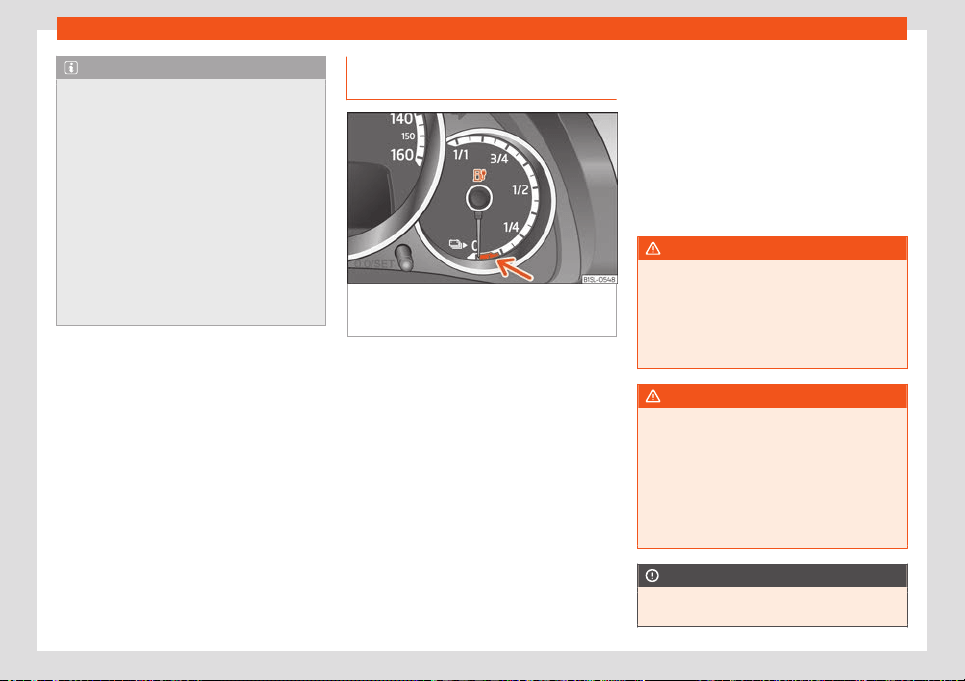
High-voltage battery
Note
●
The high-voltage batt
ery can only be
charged at charging stations that meet the
following requirements and regulations:
–
IEC 61851 and IEC 62196 (type 2 con-
nector).
●
In the event of very low or very high tem-
peratures, it may only be possible to
charge the high-voltage battery in a limited
manner.
●
To avoid possible compatibility problems
with charging infrastructures, SEAT recom-
mends the use of cables and home charg-
ing stations recommended by the Volkswa-
gen Group.
Electric range and charge level dis-
pl
ay
Fig. 148
On the instrument panel: indicator of
the high-v
olt
age batt
ery charge level with the
reserve area marked in red (arrow).
Range indication
The v
ehicl
e r
ange can be viewed on the in-
strument cluster screen
›››
page 59 and on
the application available for mobile phones
(SEAT CONNECT services
›››
page 130). The
value shown is calculated and updated
based on the driving style. Hence, the au-
tonomy may vary even with the high-voltage
battery fully charged.
High-voltage battery reserve level
The charge level display located on the in-
strument panel shows the available charge
of the battery and the reserve area, marked
in red (arrow)
›››
Fig. 148.
When the high-voltage battery charge level
has reached the reserve level, the control
lamp lights up yellow.
In this case, the relevant message
›››
page 160 will appear in the instrument
panel display. Several acoustic warnings are
also sounded.
Charge the high-voltage battery as soon as
possible to avoid the vehicle from stopping.
WARNING
If the vehicle is driven with a very low a
charge le
vel of the high-voltage battery,
the vehicle may stall in traffic, causing seri-
ous damage or accidents and injuries.
●
Always ensure that the charge level of
the high-voltage battery is sufficient!
WARNING
When the high-voltage battery charge lev-
el reaches the reserv
e level, it is possible
that certain driving properties may vary, i.e.
the acceleration behaviour of the vehicle.
●
Always adapt the speed and driving style
to the conditions of visibility, weather, road
and traffic, as well as the charge level of
the high-voltage battery.
CAUTION
The self-discharge of the high-voltage bat-
tery, for e
xample due to the vehicle being
»
163
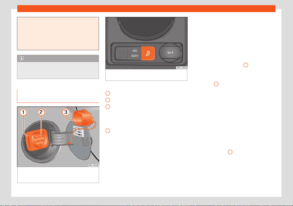
Practical tips
parked for several months, can cause dam-
age to the battery in the e
vent of high am-
bient temperature and the battery having a
low charge level.
●
Always ensure that the charge level of
the high-voltage battery is sufficient!
Note
If the outside temperature is very low and,
ther
efor
e, the high-voltage battery is very
cold, the autonomy may be reduced.
Charging from a power socket or a
char
ging st
ation (AC)
Fig. 149
Behind the cover of the battery
char
ging sock
et: char
ging socket (schematic
representation).
Fig. 150 At the bottom of the centre console:
charging mode button.
Key to
›
›
›
Fig. 149
Charging process display
Charging socket
Protective cap
The high-voltage battery of the vehicle can
be charged using alternating voltage (AC)
through the corresponding charging socket
2
.
Al
w
ays bear in mind the saf
ety warnings
›››
page 158 before starting the charging
process.
Before charging the battery, always discon-
nect the drive system
›››
page 137.
Connecting the charging cable
●
If on, remove the protective caps.
1
2
3
●
First connect the char
ging cabl
e t
o the
power supply or remove this cable from the
charging station.
●
Fully unwind the charging cable.
●
With the vehicle unlocked, press the cover
of the battery charging socket, located at the
rear of the right side, to open it
›››
Fig. 149.
●
Plug the charging connector into the
charging socket
›››
Fig. 149
2
.
As soon as the connect
or is det
ect
ed, the
charging process display lights up yellow
›››
Fig. 149
1
. The control lamp is on in the
instrument panel displ
ay.
Aut
omatic st
art of the charging process
If the programmed charge is not active, the
charging process starts immediately. Make
sure the charging station is switched on.
During the charging, the charging connector
is locked and cannot be removed.
During the charging
During the charging, the charging process
display
›››
Fig. 149
1
flashes green. The
contr
ol l
amp
flashes yellow on in the in-
strument panel display.
The remaining charging time is shown on the
instrument panel display.
164
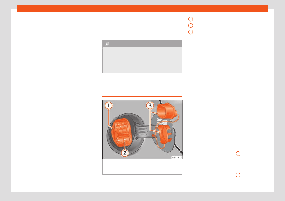
High-voltage battery
Pausing or ending the charging process
Pr
ess the char
ging mode butt
on
›››
Fig. 150
to pause the charging process. The charging
connector remains locked. The charging
process can be reactivated by pressing the
charging mode button again.
If you wish to unplug the charging connector,
unlock the vehicle using the key.
If the charging ends automatically and the
high-voltage battery is charged:
●
Unlock the vehicle with the ignition switch-
ed off.
●
Remove the charging connector from the
charging socket within 30 seconds.
●
Unplug the charging cable from the power
supply source.
●
If available, replace the protective caps.
●
Close the cover of the battery charging
socket until you hear it has engaged.
Charging for the first time and charging
after not being used for a long period of
time
When the high-voltage battery is new or has
not been charged for a long period of time, it
is possible that the battery may not reach its
maximum charge level until it is charged sev-
eral times. This is due to technical reasons
and has nothing to do with any fault in the ve-
hicle.
If you are not going to use the vehicle for a
long period of time, make sure you charge the
high-voltage battery within a period of 4
months at the latest.
Note
If once the charge is completed you leave
the charging cable connect
ed, the high-
voltage battery will not discharge due to
the use of the vehicle’s electricity consum-
ers.
Fast charge at a charging station
(CC)
Fig. 151
Behind the cover of the battery charg-
ing sock
et: char
ging sock
et (schematic repre-
sentation).
Key to
›
›
›
Fig. 151
Charging process display
Charging socket
Protective caps
Depending on the equipment, the vehicle can
be charged with direct current (DC) at a
charging station.
Take into account the general information re-
lating to charging the high-voltage battery
and the preparations to be carried out before
charging
›››
page 158.
Before charging the battery, always discon-
nect the drive system
›››
page 137.
Connecting the charging cable
Fast charge is carried out through the con-
nection located at the bottom of the charging
socket.
●
Remove the charging cable from the
charging station.
●
With the vehicle unlocked, press the cover
of the battery charging socket, located on
the side panel, to open it
›››
Fig. 151.
●
Remove the two protective caps from the
charging socket
›››
Fig. 151
3
. To remove the
bott
om pr
ot
ective cap, first remove the top
cap.
●
Plug the charging connector into the
charging socket
›››
Fig. 151
2
.
»
1
2
3
165
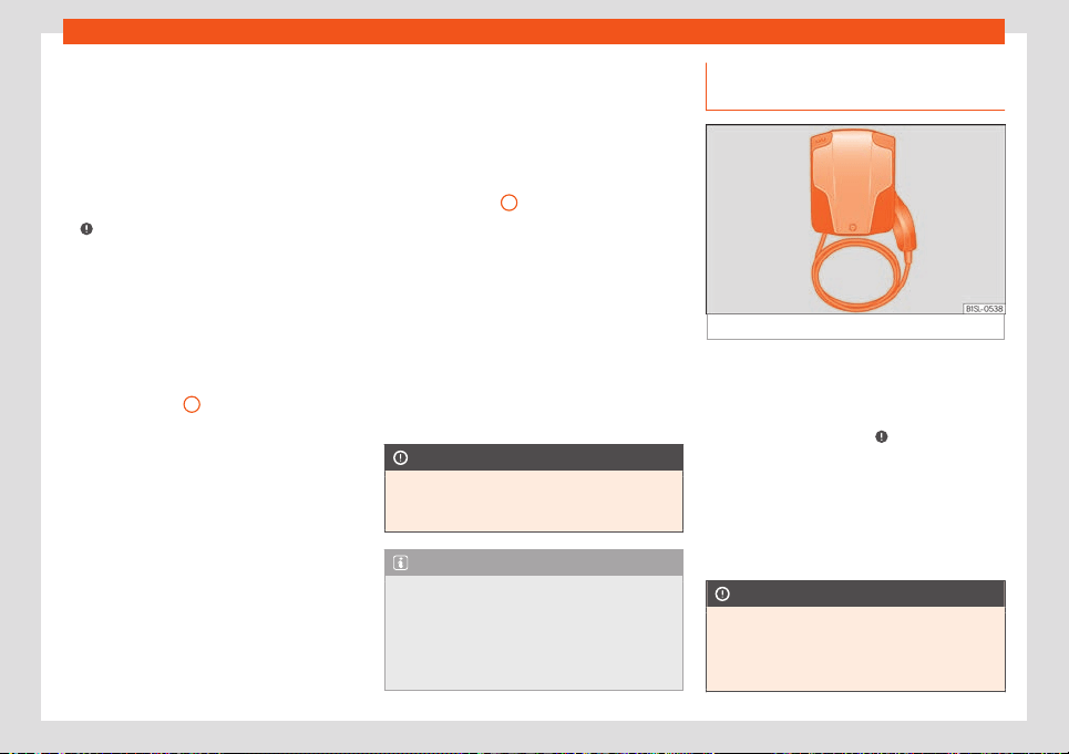
Practical tips
As soon as the connector is detected, the
char
ging pr
ocess displ
ay lights up yellow.
The charging connector is locked. The con-
trol lamp is on in the instrument panel dis-
play.
Automatic start of the charging process
In this case, activate the charging station
›››
.
The char
ging pr
ocess will st
art immediately.
During the charging, the charging connector
remains locked and cannot be removed from
the charging socket.
During the charging
During the charging, the charging process
display
›››
Fig. 151
1
flashes green. The con-
tr
ol l
amp
flashes yellow on in the instru-
ment panel display. Do not unplug the charg-
ing connector.
The remaining charging time is shown on the
instrument panel display.
Ending the charging process
The charging process can be ended by
pressing the charging mode button loca-
ted at the bottom of the centre console of the
vehicle or directly from the charging station.
Unlock the vehicle with the button on the
key or the button located on the driver’s
door. The charging process will stop for ap-
proximately 30 seconds and the charging
connector will unlock. Remove the charging
connector from the charging socket:
●
Remove the charging connector from the
charging socket.
●
Place the protective caps on the charging
socket
›››
Fig. 151
3
.
●
Close the cover of the battery charging
sock
et until you hear it has engaged. The
co
v
er should be flush-mounted on the body-
work.
Emergency release of the charging con-
nector
If it is not possible to remove the charging
connector after ending the charging process,
perform an emergency release of the same
›››
page 169 and remove it.
CAUTION
To use the charging station, bear in mind
the manufactur
er’s indications and usage
instructions.
Note
The stationary air conditioning of the vehi-
cle using a charging st
ation is only possible
during the charging process. As an alterna-
tive, the “Air conditioning without an exter-
nal power supply” can be set in the energy
manager of the infotainment system.
Charging at an AC home charging
st
ation (w
allbo
x)
Fig. 152
Home charging station (wallbox).
Charging at a fixed home charging station
(w
allbo
x)
›
››
Fig. 152 through the home power
supply achieves a higher charging power
than using a domestic socket, but not higher
than charging with DC
›››
. The charge time
diminishes significantly. The de
vice aut
omati-
cally sel
ects the maximum amperage based
on the electrical installation of the property.
Bear in mind the procedure to be followed for
charging from a power socket or a charging
station
›››
page 164.
CAUTION
The home charging station (wallbox) must
be installed by duly qualified t
echnicians.
●
Before using the home charging station
(wallbox) for the first time, ensure the
166
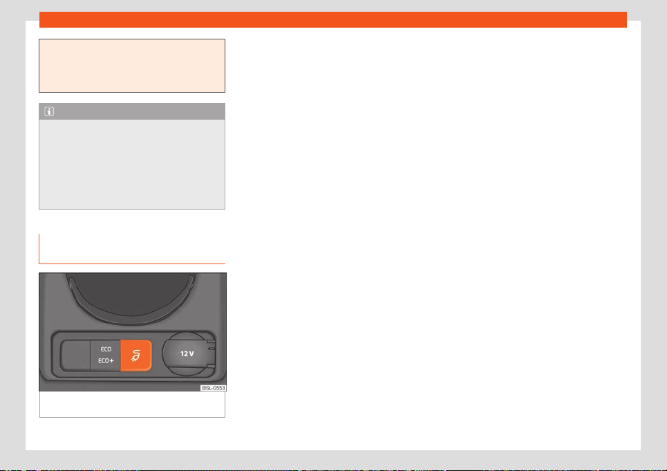
High-voltage battery
property’s electrical installation is
checked.
●
Specialised technicians shoul
d check the
electrical installation on a regular basis.
Note
The home charging station (wallbox) can
be pur
chased as an accessory.
●
Ask about home charging st
ations (wall-
box) at a SEAT dealer.
●
Bear in mind the operating instructions of
the home charging station (wallbox) before
using it.
Immediate charging and program-
med char
ging
Fig. 153 At the bottom of the centre console:
char
ging mode butt
on.
The charge mode button
›
›
›
Fig. 153 loca-
ted at the bottom of the centre console can
be used to choose between immediate and
programmed charging.
Immediate charging
The charging process of the high-voltage
battery starts immediately as soon as the the
charging cable is connected. The high-volt-
age battery will fully charge. During this time,
the charging mode button flashes.
Press the charging mode button to pause
the charging process.
If a timer is activated with a departure time,
press the charging mode button to change to
“programmed charging”.
Programmed charging
●
Open the e-manager in the app (SEAT
CONNECT services).
●
Select a timer.
●
Insert the departure time, being the time at
which the high-voltage battery must be
charged.
●
Activate the timer by ticking the verification
box .
If the charge level is very low, the high-volt-
age battery will start charging immediately
until reaching the low charge limit.
If the charging cable is plugged in, the sym-
bol of the charging mode button
›››
Fig. 153
lights up.
Not all charging stations allow programmed
charging.
Minimum charge limit of the battery
In all charging modes using a power socket,
the high-voltage battery will start charging
immediately until reaching the low charge
limit. This avoids the battery charge level
from being too low.
The value can be adjusted in the e-manager
of the SEAT CONNECT services.
Maximum charge limit of the battery
The high-voltage battery will only charge un-
til reaching the set value for the maximum
charge limit of the battery. This helps protect
the high-voltage battery
›››
page 160.
The value can be adjusted in the e-manager
of the SEAT CONNECT services.
167
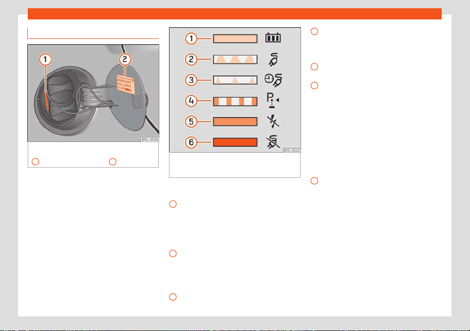
Practical tips
Charging process display
Fig. 154
Behind the cover of the battery
char
ging sock
et: char
ging process indicator
1
and information on sticker
2
.
Fig. 155 On the inside of the cover of the bat-
t
ery char
ging sock
et: sticker with information
on the charging process display.
The charging process display is a diode (LED)
l
ocat
ed ne
xt to charging socket
›››
Fig. 154
1
and it indicates the charge level. There is a
stick
er that e
xpl
ains the different indications
›››
Fig. 155.
Key to the information sticker of the charging
process display
›››
Fig. 155:
The green LED lights up permanently:
The charging process of the high-voltage
battery is complete. The battery has
reached the maximum or set charge lev-
el.
The LED flashes green: The high-voltage
battery is charging.
1
2
The LED flashes green for about 1 mi-
nut
e:
Pr
ogrammed charging is active
(departure time), but has not yet started
›››
page 167.
The LED flashes yellow: The parking
lock P is not engaged.
The yellow LED lights up briefly: The
charging connector is plugged into the
charging socket and the vehicle has de-
tected it.
The yellow LED lights up permanently:
No electrical network has been detected.
Check the power supply and the electri-
cal network. When using the charging ca-
ble for the electrical network, the protec-
tion device will display the status of the
network. Seek specialist assistance.
The red LED lights up permanently: It
has not been possible to lock the charg-
ing connector. Remove the charging con-
nector from the charging socket and plug
in again. If the fault continues, seek spe-
cialist assistance.
The LED flashes red: There is a fault in
the charging system. Seek specialist as-
sistance.
When the charging process is active, this is
displayed on the instrument panel by means
of a control lamp, and on the remaining
charge time is also displayed
›››
page 56.
3
4
5
6
168
High-voltage battery
Remaining charging time
The vehicle's remaining charging time can be
displayed on the instrument cluster displ
ay
and on the mobile app (SEAT CONNECT
services).
The charge can take longer than 10 hours
with a charging cable for power sockets.
The e-Manager shows a maximum charging
time of 10:30 hours, although it can take lon-
ger.
If the charging time is longer than 10:30
hours, the instrument cluster displays >10:30.
When the remaining charge time drops below
this value, the “>” sign disappears and the
time counts down.
While the high-voltage battery is charging,
the indicator lamp (yellow) flashes on the
instrument cluster.
Problems and solutions
The charging process will not start or has
paused
The r
el
e
vant text message will appear in the
instrument panel display.
●
Use another charging source
›››
page 160.
●
Or: unplug the charging cable of the vehi-
cle and plug it back in again.
●
Or: the charging system may be faulty.
Contact a specialised workshop.
Fast charge is not working
The relevant text message will appear in the
instrument panel display.
It is not possible to fast charge using direct
current.
Error in the charging system.
●
Contact a specialised workshop.
●
As an alternative, charge the high-voltage
battery using alternating voltage (AC).
The charge time is longer when using the
fast charge function
The charging current automatically reduces
during the charging process.
The high-voltage battery must be protected
against overheating when performing several
continuous charging cycles, for example,
when using the vehicle on a continuous basis
and with high ambient temperatures.
Emergency release of the charging
connector
Requirements:
●
The parking lock P is not engaged
›
›
›
page 140.
●
The vehicle is unlocked
›››
page 69.
●
The charging process has ended or has
paused
›››
page 161.
If despite this, it is still impossible to unplug
the charging connector, perform an emer-
gency release of the connector.
Emergency release of the charging con-
nector
●
Press the charging mode button at the
bottom of the centre console and keep it
pressed. At the same time, press the central
locking button located on the driver’s door.
●
Remove the connector from the charging
socket.
●
Have the vehicle checked by a specialised
workshop immediately.
If the problem continues, consult a special-
ised workshop.
Note
Perform the emergency release of the
charging connector only in the e
vent of a
fault in the vehicle.
169

Practical tips
Charging cable
Intr
oduction
The type of charging cable supplied with the
vehicle depends on the deliv
ery volume and
the specific technical specifications of each
country, e.g. charging connector connections
for power sockets.
The charging cables supplied from the facto-
ry are in the luggage compartment
›››
page 89 and should only be transported
there.
To charge the high-voltage battery without
problems and ensure a long useful life of the
charging cables, bear in mind the following
information and indications.
SEAT recommends to only use the charging
cables supplied from the factory.
How to maintain the charging cables in good
condition:
●
Use them with care.
●
Roll them up and roll them out completely.
●
Do not twist or bend them over sharp
edges.
●
Do not crush it and avoid driving the vehicle
over it.
●
When r
emoving them from the vehicle and
from the power supply source, only pull on
the connectors.
●
Children should not use the charging cable.
●
Keep animals away from the charging ca-
ble.
●
After use, store them safely and without
twisting.
How to maintain the protection device and
the charging connectors in good condition:
●
Do not touch the charging connector’s
contacts.
●
After using the charging cable, replace the
protective caps.
●
Protect them from intense solar radiation
(the outside temperature should not exceed
50°C (122°F)).
●
Do not drop them.
●
Protect them from immersion in fluids such
as rain water.
In the event of operating faults, SEAT recom-
mends the charging cables are checked by
one of its dealers.
If there is a fault in the power socket or in the
electrical installation, seek assistance from a
technician specialised in electrical installa-
tions.
WARNING
Using a charging cable that has been dam-
aged or tampered with can cause serious
injury and f
atal electric shocks.
●
Before each use check that the connec-
t
ors and the charging cable are undam-
aged, e.g. check for cracks.
●
Never use a charging cable that is dam-
aged or has been tampered with.
●
If the charging cable does not work prop-
erly, get a SEAT dealer to check it.
WARNING
Always plug the charging cable for power
sock
ets directly int
o a power socket. Never
use the charging cable in combination with
an extension cable, a cable reel, a power
strip or an adapter, such as a travel adapt-
er or a timer. Otherwise this could lead to
injuries caused by fire or the charging ca-
ble or the electrical installation of the
property could be damaged.
WARNING
Never charge the battery using unknown
power sock
ets or electrical installations, or
those which have not been checked by du-
ly qualified technicians. Even very low
charging currents can cause important
damages, especially fires, when using
power sockets or electrical installations
that are in poor condition. In this case, seek
assistance from a technician specialised in
electrical installations.
170
High-voltage battery
WARNING
Items that are not secured, or incorrectly
secured can cause serious injury during
sudden manoeuvres or br
aking, or in the
event of an accident.
●
Store the charging cable securely in the
luggage compartment.
●
Use the organizer/protective cover provi-
ded with the cable for this purpose.
WARNING
The high voltage system voltage is danger-
ous and can cause burns, other injuries and
fatal el
ectric shocks.
●
Only clean the charging cable when it is
unplugged.
CAUTION
A specialist in electrical installations
should check the charging cabl
e on a regu-
lar basis. A tester adapter will be needed to
check the charging cables.
CAUTION
The charging cable can be damaged if not
cleaned properly.
●
Only w
ater should be used for this pur-
pose, and never additional cleaning prod-
ucts.
●
Water should be prevented from getting
into the contacts.
For the sake of the environment
Charging cables must be disposed of in an
environmentally friendly w
ay and should
not be thrown in the household waste.
Note
Take into consideration the maximum ca-
pacity of the electrical cir
cuit used. If the
charging cable is plugged in along with
other electrical consumers into a power
socket on the same electrical circuit, this
could cause the fuse to trip. In this case, the
high-voltage battery will not charge. Dis-
connect all other electrical consumers
from the electrical circuit or use another
circuit. In this case, seek assistance from a
technician specialised in electrical instal-
lations.
Charging cable for charging sta-
tions (AC)
Fig. 156
In the luggage compartment: charg-
ing cabl
e f
or char
ging stations (depending on
the equipment).
The maximum charging current is 16 or 32
amps, depending on the v
ehicl
e
’s features
and the charging cable that is supplied
›››
.
WARNING
Charging the high-voltage battery with an
inappropriate char
ging cable could cause
short circuits, serious injuries and fatal
electrical shocks.
WARNING
The charging cable should not be used as
an extension l
ead. The charging process
could be affected.
»
171
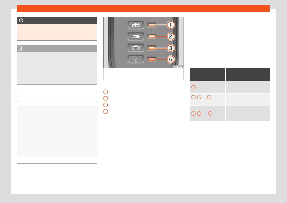
Practical tips
CAUTION
Follow the manufacturer’s instructions and
indications when using the charging sta-
tion.
Note
Charging with a 16 A charging cable is not
possible in some charging st
ations that
support 32 A. This depends on the features
of the charging station.
●
Before charging the vehicle, find out
about the available charging technology.
Charging cable for power sockets
Fig. 157 Charging cable for electrical sockets
Fig. 158 On the charging cable for power
sockets: prot
ection device.
Key to the
›
›
›
Fig. 158:
Control lamp of the power connector
Control lamp of the protection device
Control lamp of the vehicle
Failure warning lamp
The supplied charging cable is for charging
the high-voltage battery using alternating
voltage (AC) from a power socket
›››
page 164.
Also bear in mind the safety information and
indications on the charging cable label.
Protection device
Due to the electronic protection device
›››
Fig. 158, the charging connector does not
receive current until it is plugged into the
charging socket of the vehicle. When the
charging cable is plugged into the power
1
2
3
4
socket, the protection device automatically
perf
orms a self
-check
. The control and warn-
ing lamps then briefly light up and turn off.
Then the current operating status is dis-
played.
Operating displays
The control lamps that indicate the operation
turn on or flash green.
Display
›››
Fig. 158
Meaning
1
on
Charging cable connected
to the electrical netw
ork.
1
,
2
on,
3
flash-
es
a)
High-voltage battery
charging.
1
,
2
and
3
on
Charging process com-
plete
. The high-voltage bat-
tery is charged.
a)
The available supply voltage depends on each
country.
Displ
ay in the e
v
ent of the charging cable
heating
The charging cable is fitted with a tempera-
ture supervision system. The temperature su-
pervision is activated if the charging cable is
too hot due to, for example, overheating in the
luggage compartment where it is stored or
exposure to intense solar radiation.
172
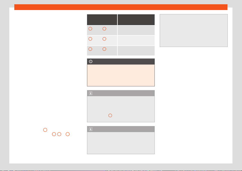
High-voltage battery
If it is still possible to charge, in addition to the
oper
ating displ
ay fl
ashing, the red warning
lamp
›››
Fig. 158 will also appear. The charg-
ing current is automatically reduced. The
charging current will increase again when the
charging cable has cooled down sufficiently.
In the event of the charging process having
paused due to the protection device, the op-
erating display will turn off and a green warn-
ing lamp will flash. The red warning lamp will
flash. Unplug the charging cable and let it
cool down. If the fault occurs again, consult a
specialised workshop.
Limiting the charging current
The charging cable limits the charging cur-
rent based in the existing power supply. De-
pending on the power socket of the country
in question, the maximum charging current
may be 6, 8 or 10 A.
The management of the battery charge ena-
bles to select a lower or maximum charging
current.
Failure indications
If the warning lamp
4
flashes or is red with-
out the oper
ating displ
ay
1
,
2
or
3
re-
maining on, this indicat
es ther
e is a f
ailure.
The charging process will pause or cancel.
Check the failure display and consult a spe-
cialised workshop if necessary.
Display
›››
Fig. 158
Meaning
1
flashes,
4
on or
flashing
Failur
e in the power supply.
2
flashes,
4
on or
flashing
Failure in the protection de-
vice.
3
flashes,
4
on or
flashing
Failur
e in the vehicle.
CAUTION
Seek information regarding the appropri-
ate charging cable and the maximum per-
mitted charging current before travelling
abroad. If possible, use the charging cable
supplied in the country in question.
Note
The charging cables supplied in countries
other than Norway are oft
en not appropri-
ate for charging from power sockets. Nor-
wegian charging cables are not fitted with
control lamp
1
because they use a differ-
ent electrical network
.
Note
If there is another consumer connected si-
multaneously to the el
ectrical network dur-
ing the charging process or if the vehicle is
in the vicinity of high-voltage cables, it is
possible that the charge cannot be per-
formed from a power socket. Simultaneous
connections to the electrical netw
ork:
●
Connection of a charger for the 12-volt
starter battery.
●
Contact with a working equipment con-
nected to the electrical network, i.e. an ele-
vating platform.
173
Practical tips
Verification and replace-
ment
Engine compar
tment
Saf
et
y warnings for performing
works in the engine compartment
The engine compartment of the vehicle is a
dangerous area. Y
ou should only perform
works in the engine compartment if you have
good knowledge of the necessary operations
and the general safety measures, and if you
have adequate tools, means and operating
fluids. Works performed inadequately, could
lead to serious injuries
›››
. In this case, seek
a specialised w
orkshop t
o perf
orm all the
works. SEAT recommends visiting a SEAT
dealership for this.
Before performing any work in the engine
compartment, always park the vehicle on
level and firm ground, taking all necessary
safety precautions.
Only specialised workshops qualified ac-
cording to the SEAT guidelines are authorised
to perform works on the high-voltage system
›››
.
WARNING
The voltage of the high-voltage system and
of the high-voltage batt
ery could be fatal!
Touching damaged high-voltage cables
(orange colour) and the high-v
oltage bat-
tery could cause an electrical shock with
deathly consequences. The high-voltage
system may be active even with the ignition
disconnected!
●
Never perform any type of work on the
high-voltage system, on the orange col-
oured high-voltage cables, on the high-
voltage components or on the high-voltage
battery. Only specialised workshops that
are qualified and approved for performing
works on high-voltage systems are author-
ised to perform works on the high-voltage
network.
●
Never modify, damage or remove the or-
ange coloured high-voltage cables, the
high-voltage components or the high-volt-
age battery, or uncouple them from the
high-voltage system.
●
To perform works close to high-voltage
components and cables, as well as on the
high-voltage battery, which require the use
of sharp tools, which may deform or re-
lease shavings, or sources of heat, such as
works involving welding, soldering, use of
hot air or thermal gluing, it is essential you
first ensure the system is not powered. The
voltage to the high-voltage battery cannot
be disconnected. Only duly qualified and
trained technicians are authorised to leave
the high-voltage system without power.
●
When there is a fault in the high-voltage
system, the engine may automatically de-
activate and the relevant display may ap-
pear on the instrument panel. In this case,
the engine will remain deactiv
ated until du-
ly qualified and trained technicians resolve
the fault.
●
When performing works on the high-volt-
age system, especially on the orange col-
oured high-voltage cables, on the high-
voltage components or on the high-voltage
battery, ensure you bear in mind the SEAT
guidelines.
WARNING
If works are performed on the high-voltage
system and on the high-volt
age compo-
nents in an inappropriate manner, this may
lead to faults in the operation, accidents
and injuries.
●
Only duly qualified and trained techni-
cians are authorised to perform works on
the high-voltage system and on any other
systems on which these may have indirect
influence.
WARNING
Any accidental movement of the vehicle
during maintenance work coul
d cause seri-
ous injuries.
●
Never perform works underneath the ve-
hicle without having first immobilised it to
prevent it from moving. When performing
works underneath the vehicle with the
wheels on the ground, the vehicle must be
174

Verification and replacement
on level ground, the wheels must be locked
and, where appropriat
e, the vehicle key
must be removed from the ignition lock.
●
If work must be performed underneath
the vehicle, take the extra precaution of
supporting it safely using suitable assem-
bly support. The jack is not suitable for this
purpose and may not withstand, which
could lead to serious injuries.
WARNING
The engine compartment of any vehicle is a
danger
ous area in which serious injuries
can be caused!
●
When perf
orming any type of work, al-
ways ensure you are extremely cautious,
and bear in mind the general safety meas-
ures. Never put yourself at risk.
●
Never perform works in the engine com-
partment if you do not have solid knowl-
edge of the necessary operations. If you
are unsure of what needs to be done, seek
a specialised workshop to perform the
works. Works performed inadequately,
could lead to serious injuries.
●
Never open the bonnet if the engine com-
partment is discharging steam or engine
coolant. Steam or hot coolant can cause
severe burns. Always wait until you stop
hearing or seeing the steam or coolant dis-
charging from the engine compartment.
●
Before opening the bonnet, al
ways wait
until the electric drive system and the high-
voltage components have cooled down.
●
If you touch hot parts of the electric drive
system, you may suffer skin burns.
●
When the electric drive system has
cooled down, before opening the bonnet
bear in mind the following:
–
Engage the handbrake, tighten it and
place the selector lever in position P or
the gear lever in neutral.
–
Switch off the ignition, remove the key
from the ignition lock and store it in a
safe place at a safe distance from the
vehicle to prevent the ignition from
turning on by mistake or power the
electrical system.
–
Always keep children away from the
engine compartment and never leave
them unsupervised.
●
When the electric drive system is hot, its
cooling system is under pressure. Never
open the coolant expansion tank cap when
the drive system is hot. Otherwise the cool-
ant could splash and cause severe burn
and other injuries.
–
Turn the coolant expansion tank cap
slowly and very carefully anticlockwise
while pressing it down slightly.
–
Always protect your face, hands and
arms from the hot coolant and steam
with a large thick cloth.
●
When refilling operating fluids, ensur
e
they do not spill onto the components of
the engine or onto the exhaust system.
These liquids could cause a fire.
WARNING
The electrical system is under high voltage
and can cause el
ectrical shocks, burns, se-
rious injuries and ev
en death!
●
Never short circuit the electrical system.
The 12-volt battery may explode.
●
To reduce the risk of suffering a fatal
electrical shock and serious injuries, while
the drive system is connected or is con-
necting, never touch the high-voltage com-
ponents, the high-voltage battery or the
high-voltage system, especially the orange
coloured high-voltage cables.
WARNING
The engine compartment contains rotating
parts that could cause serious injuries.
●
Ne
ver insert your hand in the radiator fan
or around that area. All the rotor blades
can cause serious injuries. The fan acti-
vates depending on the temperature and
can switch on automatically, even with the
ignition disconnected and with the key re-
moved from the ignition lock.
●
If you have to perform works during the
disconnection of the drive system or which
it connected, bear in mind that the rotating
»
175

Practical tips
parts (i.e. the radiator fan) represent a fatal
hazard. Al
ways act with extreme care.
–
Always ensure that no part of your
body, or any jewellery or tie, loose
clothing, loose long hair can become
trapped in the rotating parts of the en-
gine. Before performing works in the en-
gine compartment, remove any jewel-
lery or tie you may be wearing, tie up
your hair if it is long and gather any
loose clothing to prevent them from be-
coming tangled with the engine parts.
–
Never step on the accelerator pedal
without paying attention, always do so
with extreme care. The vehicle could
move, even if the electronic parking
brake is activated.
●
Never leave any object in the engine
compartment, i.e. cloths or tools. These ob-
jects could cause functional failures, dam-
age to the electric drive system and even a
fire.
WARNING
If additional insulating elements (i.e. blan-
kets) are pl
aced in the engine compart-
ment, this could prevent the electric drive
system from operating correctly, could
cause a fire and lead to serious injuries.
●
Never cover the electric drive system
with blankets or other insulating materials.
WARNING
The operating fluids and some materials of
the engine compartment are highly fl
am-
mable and could cause a fire and serious
injuries! · Never smoke in the vicinity of the
engine compartment.
●
Never perform works close to unprotec-
ted flames or sparks.
●
Never spill operating fluids on the elec-
tric drive system. The liquids could ignite
upon coming into contact with the hot
parts of the electric drive system and
cause injuries.
●
When you must perform works on the on-
board 12-volt electrical system, bear in
mind the following:
–
Always disconnect the 12-volt battery.
Ensure the vehicle is unlocked when
disconnecting the 12-volt battery, oth-
erwise the anti-theft alarm will trigger.
–
Never perform works in the vicinity of
heating elements, water boilers or un-
protected flames.
●
Always have a fire extinguisher close-by,
ensuring it is operational and had been
checked.
CAUTION
When refilling or changing the operating
fluids, ensure you pour the correct fluids in-
t
o their corresponding filler caps. Using the
wrong operating fluids could cause severe
functional failures and damage to the en-
gine.
CAUTION
After an accident or having hit an obstacle
with the v
ehicle underside
, the high-volt-
age battery must be checked by duly
qualified and trained technicians.
For the sake of the environment
Operating fluids that overflow from the ve-
hicle contaminat
e the environment. There-
fore, check underneath the vehicle on a
regular basis. If there are marks left by op-
erating fluids on the ground, consult a spe-
cialised workshop and request the vehicle
be checked. If any operating fluid leaks out,
dispose of it in the correct manner.
Working in the engine compart-
ment
Before performing works in the engine com-
partment, al
w
ays perf
orm the following oper-
ations in the order indicated
›››
:
●
Place the vehicle on level and firm ground,
t
aking all necessary saf
et
y precautions.
●
Press the brake pedal and keep it pressed
until you disconnect the drive system.
●
Engage the handbrake and tighten it.
176
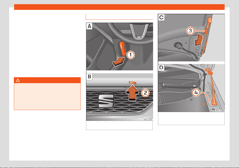
Verification and replacement
●
Pl
ace the sel
ect
or lever to the P
›››
page 140 position.
●
Disconnect the drive system
›››
page 137.
●
Remove the vehicle key outside the vehicle
and keep it at a distance to prevent the drive
system from connecting by mistake and pow-
ering the electrical system
›››
page 138.
●
Wait for the electric drive system to cool
down.
●
Keep children and other people away from
the engine compartment.
●
Ensure the vehicle cannot go into motion
unexpectedly.
WARNING
For your own safety, do not ignore this im-
portant check list, otherwise this coul
d
cause accidents and serious injuries.
●
Always follow the indications on the
check list and always bear in mind the gen-
eral safety measures.
Opening and closing the bonnet
Fig. 159 : Release lever in the footwell on
the driv
er side : Release lever on the bonnet
Fig. 160 : Bonnet securing rod in the bonnet.
: Bonnet supported by the bonnet securing
r
od
Opening the bonnet
The bonnet is r
el
eased fr
om inside the vehi-
cle.
Before opening the bonnet, make sure that
the windscreen wiper arms are in place
against the windscreen.
»
177
Practical tips
●
Open the door and pull the l
e
v
er under the
dashboard
›››
Fig. 159
1
.
●
Lift the bonnet up slightly while pressing the
r
el
ease l
ever
›››
Fig. 159
2
in the direction of
the arr
o
w t
o completely open the bonnet.
●
Take out the bonnet support rod from its
clip in the direction of the arrow
›››
Fig. 160
3
and place it in the corresponding open
position
4
(arrow).
Cl
osing the bonnet
●
Slightly lift the bonnet.
●
R
el
ease the bonnet stay and replace it in its
support.
●
At a height of approximately 30 cm let it fall
so it locks.
If the bonnet does not close, do not press
downwards. Open it again and let it fall as
mentioned above.
WARNING
If the bonnet is not properly closed, it could
open unexpectedly whil
e in motion and im-
pede forward visibility. This could cause
accidents and lead to serious injuries.
●
After closing the bonnet, ensure that the
lock is duly engaged in the lock carrier. The
bonnet must be at the same level as the
adjacent parts of the bodywork.
●
If while in motion you notice the bonnet is
not properly cl
osed, stop the vehicle imme-
diately and close the bonnet.
●
Open and close the bonnet only when
there is nobody in its path.
CAUTION
●
T
o avoid damage t
o the bonnet and to the
wiper arms, open the bonnet only when the
wiper is disconnected and the wiper arms
are positioned on the windscreen.
●
Before starting to move, always place the
wiper arms on the windscreen.
Cooling system
Contr
ol l
amp
Flashes red
Excessive engine coolant temperature.
Stop the vehicl
e! Stop the vehicle safely as soon
as possible. Disconnect the drive system and allow to
cool until the lamp switches off. If the lamp does not
switch off once the drive system has cooled down,
seek specialist assistance.
Insufficient engine coolant level.
Stop the vehicl
e! Check the coolant level once
the drive system has cooled down and, if it is low, re-
fill with engine coolant
›››
page 179.
Flashing red next to the dis-
play --.- on the instrument
panel.
Engine cool
ant system faulty.
Stop the vehicl
e! Seek specialist assistance.
Several control and warning lamps light up
for a fe
w seconds when the ignition is switch-
ed on while the function is verified. They will
switch off after a few seconds.
WARNING
Observe the safety warnings
›››
in Con-
trol and warning l
amps on page 66.
Coolant specifications
The engine cooling system is supplied from
the f
act
ory with a specially tr
eated mixture of
water and at least 40 % of the additive
G12evo (TL-VW 774 J), purple. This mixture
gives the necessary frost protection down to
-25°C (-13°F) and protects the light alloy
parts of the engine cooling system against
corrosion. It also prevents scaling and con-
siderably raises the boiling point of the cool-
ant.
To protect the cooling system, the percent-
age of additive must always be at least 40 %,
even in warm climates where anti-freeze pro-
tection is not required.
178
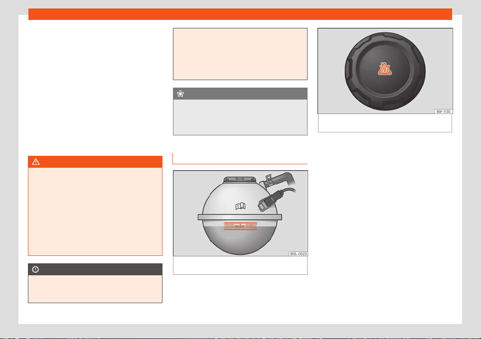
Verification and replacement
If for weather reasons further protection is
necessary, the pr
oportion of additiv
e may be
incr
eased, but only up to 60 %; otherwise an-
tifreeze protection will diminish and this will
worsen cooling.
When the coolant is topped up, use a mixture
of distilled water and at least 40 % of the
additive G12evo for optimal protection
against corrosion. Mixing G12evo with G13
(TL-VW 774 J), G12 plus-plus (TL-VW 774 G),
G12 plus (TL-VW 774 F), G12 (red) or G11
(green blue) engine coolants decreases pro-
tection again corrosion and should be avoi-
ded.
WARNING
If there is not enough anti-freeze in the
coolant system, the engine may f
ail lead-
ing to serious damage.
●
Ensure that the percentage of additive is
correct for the lowest expected ambient
temperature in the zone in which the vehi-
cle is to be used.
●
When the outside temperature is very
low, the coolant could freeze and the vehi-
cle would be immobilised.
CAUTION
The original additives should never be
mixed with coolants which ar
e not ap-
proved by SEAT.
●
If the fluid in the expansion tank is not
purpl
e but is, for example, brown, this indi-
cates that the G12evo additive has been
mixed with an inadequate coolant. The
coolant must be changed as soon as possi-
ble if this is the case!
For the sake of the environment
Coolants and additives can contaminate
the envir
onment. If any fluids are spill
ed,
they should be collected and correctly dis-
posed of, with respect to the environment.
Refilling coolant
Fig. 161 In the engine compartment: marking
on cool
ant e
xpansion t
ank.
Fig. 162 Engine compartment: coolant expan-
sion tank cap.
The coolant tank is located in the engine
compartment
›
›
›
page 174.
Top up coolant when the level is below the
(minimum) mark.
Checking coolant level
–
Park the vehicle in a horizontal position.
–
Switch the ignition off.
–
Read off the coolant level on coolant ex-
pansion tank. When the drive system is
cold, the coolant level should be between
the marks
›››
Fig. 161. With the drive system
hot, the level may be slightly above the top
mark.
Topping up coolant
–
Allow the drive system to cool.
»
179
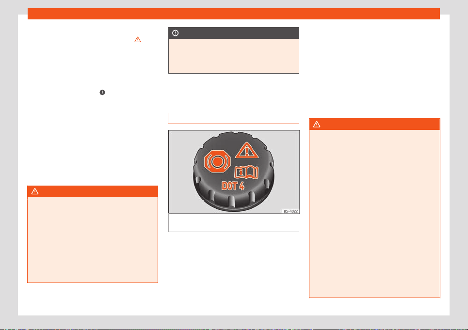
Practical tips
–
Unscr
e
w the cap sl
owly and carefully while
pressing downwards on the cap.
›››
.
–
Only refill the coolant if the coolant expan-
sion t
ank still cont
ains cool
ant; otherwise
you could damage the drive system. If
there is no coolant in the expansion tank, do
not continue driving. You should obtain pro-
fessional assistance
›››
.
–
If there is still some coolant in the expansion
t
ank
, t
op up to the upper mark.
–
Top up with coolant until the level becomes
stable.
–
Screw the cap back on correctly.
If there is a coolant leak, take the vehicle spe-
cialised workshop to have the cooling system
examined.
WARNING
●
The cooling system is under pressur
e. Do
not open the coolant expansion tank cap
when the drive system is hot: risk of burns!
●
Store the antifreeze in its original con-
tainer and keep it out of reach of children.
●
If working inside the engine compart-
ment, remember that, even when the igni-
tion is switched off, the radiator fan may
start up automatically, and therefore there
is a risk of injury.
CAUTION
If you run out of coolant in the expansion
tank, park the v
ehicle in a safe place and
do not continue driving. Obtain technical
assistance.
Brake fluid
Check and refill the brak
e fluid
Fig. 163 Engine compartment: brake fluid res-
erv
oir cap
.
The brake fluid reservoir is located in the en-
gine compartment.
Checking the br
ak
e fluid l
evel
The brake fluid level must be between the
and markings.
However, if the brake fluid level goes down
noticeably in a short time, or drops below the
mark, there may be a leak in the brake
system. Seek specialist assistance. A warning
light on the instrument panel display monitors
the brake fluid level
›››
page 65.
Changing brake fluid
We recommend that you have the brake fluid
changed by a Technical Service.
WARNING
If the brake fluid level is low or unsuita-
ble/old br
ake fluid is used, the brake sys-
tem may fail or braking power may be re-
duced.
●
Check the brake system and the brake
fluid level regularly!
●
When the brake fluid is used and brakes
are subjected to extreme braking forces,
bubbles of vapour form in the brake sys-
tem. These bubbles can significantly re-
duce braking power, notably increasing
braking distance, and could result in the to-
tal failure of the brake system.
●
Be sure to always use the correct brake
fluid. Only use brake fluid that expressly
meets the VW 501 14 standard.
●
You can buy VW 501 14 standard brake
fluid in a SEAT dealership or a SEAT Official
Service. If none is available, use only high-
quality brake fluid that meets DIN ISO 4925
180
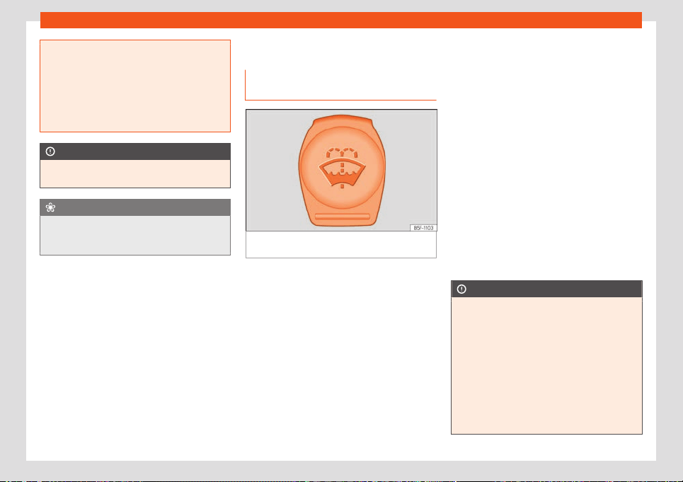
Verification and replacement
CLASS 4 standards, or USA Standards
FMVSS 116 DOT 4.
●
The r
eplacement brake fluid must be
new.
●
Brake fluid should be stored in the closed
original container in a safe place out of
reach of children. Risk of poisoning!
CAUTION
Brake fluid should not come into contact
with the v
ehicle paintw
ork, as it is abrasive.
For the sake of the environment
Brake fluid is an environmental pollutant.
Collect any spilt service fluids and allo
w a
professional to dispose of them.
Windscreen washer reservoir
Checking the l
e
v
el of the window
washer tank and refilling it
Fig. 164
In the engine compartment: window
w
asher t
ank cap
.
The windscreen washer reservoir is in the en-
gine compartment.
Check the w
at
er l
evel in the windscreen
washer reservoir regularly and top up as re-
quired.
The window washer tank contains liquid de-
tergent for the windscreen and rear window.
●
Open the bonnet
›››
page 176.
●
The window washer tank is marked with the
symbol on the cap.
●
Check there is enough windscreen water in
the reservoir.
Plain water is not enough to clean the wind-
screen and headlights. We recommend that
you always add a product to the windscreen
washer fluid.
Recommended windscreen wipers
●
For the hottest seasons we recommend
summer G 052 184 A1 for clear glass. Propor-
tions of the mixture in the washer fluid tank:
1:100 (1 part concentrate per 100 parts wa-
ter).
●
All year round, G 052 164 A2 for clear glass.
Approximate proportion of the winter mixture,
up to -18°C (0°F): 1:2 (1 part concentrate per 2
parts water); otherwise, a 1:4 proportion of
mixture in the washer fluid tank.
The capacity of the window washer tank can
be found in
›››
page 211.
CAUTION
If the water from the windscreen washer
does not contain enough anti-free
ze, it may
freeze on the windscreen and rear window,
reducing forward and rear visibility.
●
In winter, ensure the windscreen washer
contains enough anti-freeze.
●
In cold conditions, you should not use the
windscreen wiper system unless you have
warmed the windscreen with the ventila-
tion system. The antifreeze could freeze on
the windscreen and reduce visibility.
»
181
Practical tips
CAUTION
Never mix an unsuitable antifreeze or other
similar additives with the windscr
een wash-
er water. A greasy layer may be formed on
the windscreen which will impair visibility.
●
Use clean water with a window cleaner
recommended by SEAT.
●
If necessary, add a suitable antifreeze to
the water in the reservoir.
CAUTION
●
Do not mix cleaning products r
ecommen-
ded by SEAT with other products. This
could lead to flocculation and may block
the windscreen washer jets.
●
When topping up service fluids, make ab-
solutely certain that you fill the fluids into
the correct reservoirs. Using the wrong flu-
ids could cause serious malfunctions and
engine damage!
●
Not having windscreen wiper fluid re-
duces visibility through the windscreen,
and leads to loss of visibility in headlights
in models with headlight washer.
12-volt battery
Intr
oduction
The 12-volt battery is part of the electrical
syst
em and in the e
v
ent of a high-voltage
system failure it supplies power to safety-crit-
ical vehicle systems. The 12-volt battery is
checked as part of inspection work and re-
placed if necessary.
You may only work on the electrical system if
you are familiar with the necessary proce-
dures and general safety measures, and if
you have the correct fluids and operating
equipment, as well as the right tools. Work
done incorrectly can cause serious injuries
›››
in Location of the 12 volt battery on
page 182. Get a qualified est
ablishment t
o
do all w
ork. Seat recommends Seat dealer-
ships for this purpose.
You will find information about any warning
and control lamps that may light up in the
“Problem solving” section at the end of the
chapter
›››
page 185.
Location of the 12 volt battery
The 12 volt battery is located in the engine
compartment.
Expl
anation of the w
arning indications on the
12-v
olt battery
Wear eye protection.
Battery acid is extremely corrosive. Wear pro-
t
ective gl
oves and eye protection. Rinse any
splashes of electrolyte with plenty of water.
Fires, sparks, open flames and smoking are
prohibited.
The 12-v
olt battery should only be charged in
a well-v
entilated zone. Risk of explosion!
Keep children away from acid and the 12-volt
battery.
Alw
ays follow the instruction manual.
WARNING
Work on the 12 volt battery and electrical
syst
em can cause sev
ere burns, fires, and
electric shock. Before doing any work, the
following warning instructions must be
read and followed, and the following pre-
cautions must be taken:
●
Before doing any work on the 12-volt bat-
tery, switch off the ignition and all electri-
cal consumers and disconnect the nega-
tive cable from the 12-volt battery.
●
Keep children away from electrolyte and
the 12-volt battery at all times.
●
Always wear protective goggles and
gloves.
●
Electrolyte is highly corrosive. It can
caused skin burns and blindness. When
handling the 12-volt battery you must par-
ticularly protect your hands, arms and face
from splashes of electrolyte.
●
Never smoke or work close to naked
flames or sparks.
182
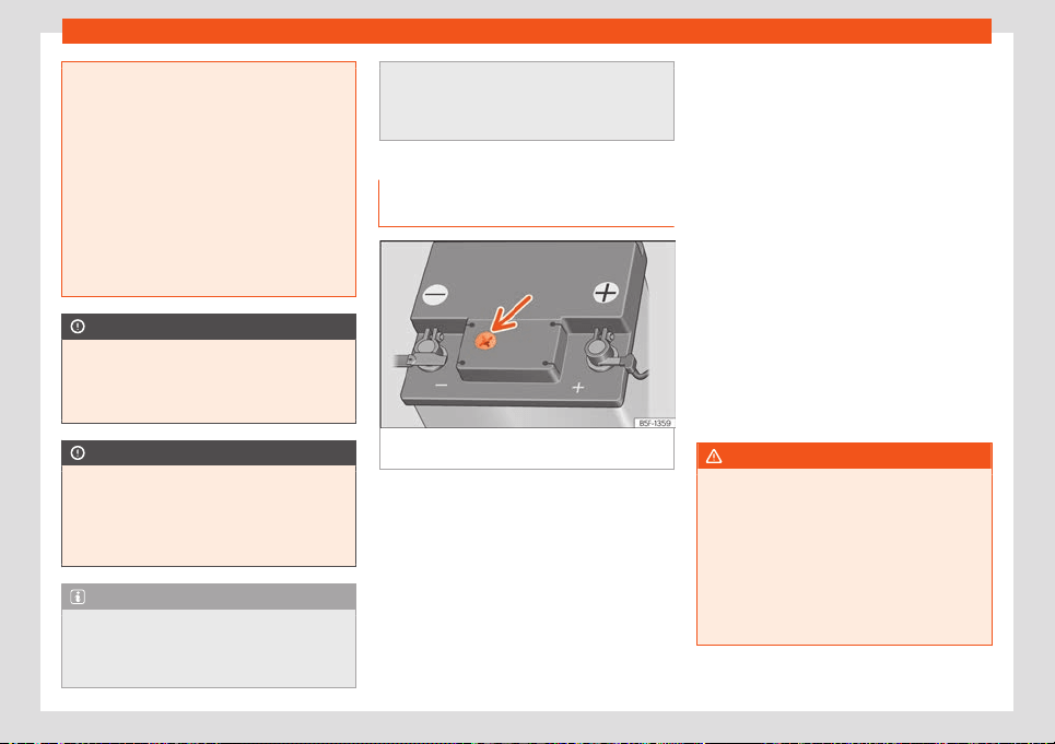
Verification and replacement
●
Avoid generating sparks when handling
cabl
es and electronic devices, or as a re-
sult of an electrostatic discharge.
●
Never short the battery terminals.
●
Never use a damaged 12 volt battery. It
could explode. A damaged 12 volt battery
should be replaced immediately.
●
Never use a frozen 12 volt battery. A dis-
charged 12 volt battery may freeze at a
temperature of just 0 °C (+32 °F). A frozen
12 volt battery should be replaced immedi-
ately.
CAUTION
The 12 volt battery should not be exposed
to direct sunlight f
or a long time.
●
Ultraviolet rays could damage the bat-
tery case.
CAUTION
If it is not going to be used for a long period
of time, the 12 volt batt
ery should be pro-
tected from frost.
●
The 12 volt battery can freeze and be-
come unusable.
Note
When turning on the drive system with a
drained or newly r
eplaced 12-volt battery,
or after a jump start, it is possible that
some system settings (time, date, personal
comfort options and programs) may be lost
or deleted. Check and corr
ect these set-
tings once the 12-volt battery is sufficiently
charged.
Check the 12-volt battery electro-
lyte le
vel
Fig. 165
Sight glass on the top of the 12 volt
batt
ery (schematic r
epr
esentation).
The electrolyte level of the 12 volt battery
shoul
d be check
ed periodically in cases of
high mil
eage, in countries with hot climates
and if an old 12-volt battery is used. Other-
wise, the 12-volt battery is maintenance-free.
Preparations
●
Prepare the vehicle for work in the engine
compartment
›››
page 176
●
Open the bonnet
›››
page 177
Check the electrolyte level (12-volt bat-
teries with a sight glass)
●
Ensure sufficient lighting to clearly identify
the colour indication displayed in the circular
sight glass located at the top of the 12-volt
battery (arrow)
›››
Fig. 165. Never use naked
flames or objects that burn without a flame
as lighting.
●
The colour displayed in the circular sight
glass changes depending on the electrolyte
level in the 12-volt battery.
There are two different colours:
The electrolyte level of
the 12-volt battery is too low. Go to a
specialised workshop to have the bat-
tery checked and replaced if necessary.
The electrolyte level of the 12-volt bat-
tery is correct.
WARNING
Working on 12-volt batteries can cause se-
vere burns, e
xplosions and electric shock.
●
Always wear protective goggles and
gloves.
●
Electrolyte is highly corrosive. It can
caused skin burns and blindness. When
handling the 12-volt battery you must par-
ticularly protect your hands, arms and face
from splashes of electrolyte.
»
Yellow or colourless:
Black:
183

Practical tips
●
Never t
urn the 12-volt battery over. Elec-
trolyte could leak out of the vents and
cause burns.
●
Never open a 12-volt battery.
●
If the electrolyte splashes onto the skin
or eyes, rinse the affected area with cold
water for a few minutes. Then seek medical
care immediately.
●
Seek medical care immediately if you in-
gest the acid.
Charging, replacing, disconnect-
ing and connecting the 12-v
olt bat
-
t
ery
If the 12-volt battery is suspected of being
damaged or def
ectiv
e
, have it checked by a
qualified establishment.
Charging the 12-volt battery
The 12-volt battery must be charged at a
qualified establishment, as the factory fitted
12-volt battery technology requires a voltage
limited charge
›››
. SEAT recommends visit-
ing a SEAT deal
ership f
or this.
R
eplacing the 12-volt battery
The 12-volt battery is developed to suit its lo-
cation and has special safety features. When
a 12-volt battery needs to be replaced, be-
fore buying a new one you must ask a SEAT
dealership about electromagnetic compati-
bility, size and maintenance, power and safe-
ty requirements that the new battery must
meet. The 12-volt battery's vent must always
be on the side of the negative terminal and
the vent on the positive terminal must always
be closed.
A maintenance-free battery that meets the
TL 825 06 and VW 7 50 73 standards must al-
ways be used. These standards must be dat-
ed October 2014 or later.
The 12-volt battery must always be replaced
by a qualified establishment, as it is necessa-
ry to adjust the vehicle's electronic system as
part of its replacement. Only a qualified es-
tablishment has the appropriate technology
to make this adjustment correctly. SEAT rec-
ommends that the 12-volt battery be re-
placed by a SEAT dealer.
Disconnecting the 12-volt battery
If the 12-volt battery needs to be disconnec-
ted from the vehicle's electrical system, these
steps should be followed:
●
Switch off the ignition and all electrical
consumers.
●
Before disconnecting the battery, unlock
the vehicle or theft alarm system will activate.
●
First disconnect the negative cable and
then the positive cable
›››
.
Connecting the 12-volt battery
●
Before reconnecting the 12-volt battery,
disconnect all el
ectrical consumers and the
ignition.
●
First r
econnect the positiv
e cable and then
the negative one
›››
.
Aft
er connecting the 12-v
olt batt
ery and turn-
ing on the ignition, different indicator lights
may come on. They will turn off when a short
distance is driven at approximately 15-20
km/h. If the warning indicators remain lit,
please visit a qualified establishment to have
the vehicle checked.
If the 12-volt battery has been disconnected
for a long time, it's possible that the next serv-
ice appointment might not be displayed or
calculated correctly.
›››
page 63 . Respect
the maximum service intervals permitted
›››
page 194.
Automatic disconnection of consumers
Thanks to the smart management of the on-
board network, when the 12-volt battery is
overcharged different measures are taken to
prevent the 12-volt battery from discharging:
●
If necessary, the power in the largest con-
sumers is limited, or they are disconnected
completely in an emergency.
However, on-board network management
cannot always prevent the 12-volt battery
184
Verification and replacement
from discharging. For example, if the ignition is
k
ept on f
or a l
ong time with the engine stop-
ped or if the parking or side light is left on for
a long time.
The 12-volt battery discharges
●
if electrical consumers are used while the
drive system is switched off.
WARNING
Incorrectly installing the 12-volt battery or
using an inappropriate 12-v
olt battery can
cause short circuits, fires and severe inju-
ries.
●
Maintenance-free and leak-protected
12-volt batteries must always be used, and
they must have the same characteristics,
specifications and dimensions as the fac-
tory-fitted 12-volt battery.
WARNING
A highly explosive gas mixture is generated
during the charging process of the 12-v
olt
battery.
●
Only charge the 12-volt battery in a well-
ventilated place.
●
Never charge a frozen or thawed 12-volt
battery. A discharged 12 volt battery may
freeze at a temperature of just 0 °C (+32
°F).
●
Any 12-volt battery that has frozen must
be replaced.
●
Incorrectly connected connection cabl
es
can cause a short circuit. First connect the
positive cable and then the negative one.
CAUTION
Never connect power supply accessories,
such as sol
ar panels or batt
ery chargers, to
the 12-volt socket or cigarette lighter to
charge the 12-volt battery. This could dam-
age the vehicle's electrical system.
For the sake of the environment
●
12-volt batteries cont
ain toxic substan-
ces such as sulphuric acid and lead. The 12
volt battery must be disposed of in accord-
ance with current regulations.
●
Electrolyte can contaminate the environ-
ment. Used vehicle fluids must be collected
and disposed of properly.
Troubleshooting
The indicator lamp lights up r
ed and
this text message is displayed: 12 volt
power supply interrupted.
Stop the vehicle! The vehicle should be
stopped as soon as it is possible and safe to
do so. The 12-volt battery does not charge
while driving.
●
Disconnect any unnecessary electrical
consumers.
●
Go to a qualified est
ablishment to get the
system checked.
The following text message is displayed:
Error: 12 volt power system.
The connection between the on-board net-
work and the 12-volt battery has been inter-
rupted. If the drive system switches off in this
situation, it should not be switched on again
and the vehicle should be jump started
›››
page 45 or professional assistance should
be sought.
●
Go to a qualified establishment to get the
system checked.
The following text message is displayed:
Error: Switching off the 12 volt
battery.
The 12-volt battery supervision system does
not work.
●
Go to a qualified establishment to get the
system checked.
The following text message is displayed:
Error: 12-volt battery: Workshop.
The 12 volt vehicle battery has almost
reached the end of its useful life.
»
185

Practical tips
●
Go t
o a qualified est
ablishment and r
e-
quest a check and, if necessary, the replace-
ment of the 12-volt battery
›››
page 184.
The following text message is displayed:
Check the 12-volt battery!
The connection between the on-board net-
work and the 12-volt battery has been inter-
rupted.
●
Go to a qualified establishment to get the
system checked.
The following text message is displayed:
12-volt battery low.
Deficient charging of the 12-volt battery due
to circumstances such as low temperatures.
●
Go for a short drive to re-charge the 12-volt
battery.
Wheels
Wheel
s and t
yr
es
General notes
–
When driving with new tyr
es, be especially
careful during the first 500 km (300 miles).
–
If you have to drive over a kerb or similar
obstacle, drive very slowly and as near as
possible at a right angle to the obstacle.
–
Check from time to time if the tyres are
damaged (punctures, cuts, cr
acks or
dents). Remove any foreign objects em-
bedded in the treads.
–
Damaged wheels and tyres must be re-
placed immediately.
–
Keep grease, oil and fuel off the tyres.
–
Replace any missing valve caps as soon as
possible.
–
Mark the wheels before taking them off so
that they rotate in the same direction when
put back.
–
When removed, the wheels or tyres should
be stored in a cool, dry and preferably dark
place.
Low profile tyres
Low profile tyres have a wider tread, a larger
wheel diameter and a lower sidewall height.
Therefore, its driving behaviour is more agile.
Low profile tyres may deteriorate more quick-
ly than standard tyres, for instance due to
strong knocks, potholes, manhole covers and
kerbs. Correct tyre pressure is very important
›››
page 189.
To avoid damage to tyres and wheels, drive
with special care when driving on roads in
poor condition.
Visually check your wheels every 3000 km.
If the tyres or rims have received a heavy im-
pact or have been damaged, have a special-
ised workshop check whether or not it is nec-
essary to change the tyre.
Low profile tyres may deteriorate more quick-
ly than standard tyres.
Concealed damage
Damage to tyres and rims is often not readily
visible. If you notice unusual vibration or the
car pulling to one side, this may indicate
that one of the tyres is damaged. Reduce
speed immediately if there is any reason to
suspect that damage may have occurred. In-
spect the tyres for damage. If no external
damage is visible, drive slowly and carefully
to the nearest specialised workshop and
have the car inspected.
186
Wheels
Foreign objects inserted in the tyre
●
Do not remove foreign bodies if they have
penetr
at
ed thr
ough the tyre wall!
●
If the vehicle comes with a tyre mobility
system, where necessary seal the damaged
tyre as shown in section
›››
page 35. Use a
specialised workshop for repair or replace-
ment. SEAT recommends visiting a SEAT
dealership for this.
The sealant at the lower part of the tyre tread
wraps around the foreign body and provision-
ally seals the tyre.
Tyres with directional tread pattern
An arrow on the tyre sidewall indicates the di-
rection of rotation on single drive tyres. Al-
ways note the direction of rotation indicated
when mounting the wheel. This makes sure
that optimal use is made of tyre properties in
terms of aquaplaning, grip, excessive noise
and wear.
Subsequent fitting of accessories
If you wish to change or fit wheels, rims or
wheel trims, we recommend that you consult
with a SEAT Official Service centre for advice
regarding current techniques.
Speed symbols
The speed rating indicates the maximum
speed permitted for the tyres.
max. 150 km/h (93 mph)
max. 160 km/h (99 mph)
max. 170 km/h (106 mph)
max. 180 km/h (112 mph)
max. 190 km/h (118 mph)
max. 200 km/h (124 mph)
max. 210 km/h (130 mph)
max. 240 km/h (149 mph)
Some manufacturers use the letters “ZR” for
tyres with a maximum authorised speed
above 240 km/h (149 mph).
WARNING
●
New tyr
es do not have maximum grip dur-
ing the first 500 km. Drive particularly
carefully to avoid possible accidents.
●
Never drive with damaged tyres. This
may cause an accident.
●
If you notice unusual vibrations or if the
vehicle pulls to one side when driving, stop
the vehicle immediately and check the
tyres.
●
Never use old tyres or those with an un-
known history of use.
P
Q
R
S
T
U
H
V
New wheels and tyres
It is best to have all wheels and tyres serviced
by a specialised workshop. Ther
e they have
the required knowledge, the special tools and
the corresponding spare parts.
●
Even winter tyres lose their grip on ice. If you
have installed new tyres, drive the first 500
km carefully and at a moderate speed.
●
All four wheels must be fitted with tyres of
the same type, size (rolling circumference)
and, if possible, tread pattern.
●
When changing tyres, do not change just
one; change at least two on the same axl
e.
●
If you want to equip your vehicle with a
combination tyres and rims that are different
to those fitted in the factory, inform your spe-
cialised workshop before purchasing them
›››
The sizes of the rims and tyres approved for
your v
ehicl
e ar
e listed in the vehicle docu-
mentation (e.g. EC Certificate of Conformity
or COC document
1)
). The vehicle documen-
tation varies depending on the country of res-
idence.
If the type of spare wheel is different form the
normal wheels — e.g. in the case of winter
tyres or particularly wide tyres — the spare
wheel should only be used temporarily in the
»
1)
COC = certificate of conformit
y.
187

Practical tips
event of a puncture, and the vehicle should
be driv
en with car
e
. Refit the normal road
wheel as soon as possible.
Manufacturing date
The manufacturing date is also indicated on
the tyre sidewall (or on the inside face of the
wheel):
DOT ... 2218 ...
it means, for example, that the tyre was man-
ufactured in the 22nd week of 2018.
WARNING
●
Use only combinations of tyres and rims,
as w
ell as suitable wheel nuts, approved by
SEAT. Otherwise the vehicle may be dam-
aged, causing an accident.
●
For technical reasons it is not possible to
use wheels of other vehicles; in some cases
not even wheels from the same vehicle
model should be used.
●
Always ensure that the tyres you have
chosen have adequate clearance. When
selecting replacement tyres, do not rely
entirely on the nominal tyre size marked on
the tyre, since the nominal tyre size can dif-
fer significantly depending on the manu-
facturer. Lack of clearance can damage
the tyres or the vehicle and, as a result, en-
danger road safety. Risk of accident!
●
Only use tyres that are over 6 years old in
an emergency, and drive with due care.
●
The fitting of tyres with run-fl
at proper-
ties is not permitted on your vehicle! Pro-
hibited use can cause accidents or can
damage your vehicle.
●
If decorative hubcaps are subsequently
fitted, make sure that they allow enough air
in to cool the braking system. Risk of acci-
dent!
For the sake of the environment
Old tyres must be disposed of according to
the l
aws in the country concerned.
Note
●
A SEAT Service Centre should be consul
-
ted to find out whether wheels or tyres of
different sizes to those originally fitted by
SEAT can be fitted, and to find out about
the combinations allowed between the
front axle (axle 1) and the rear axle (axle 2).
●
Never mount used tyres if you are not
sure of their “previous history”.
Tyre life
Fig. 166 Location of the tyre pressure sticker.
Correct inflation pressures and sensible driv-
ing habits will incr
ease the useful lif
e of your
t
yres.
●
Check tyre pressure at least once a month,
and also prior to any long trip.
●
The tyre pressure should only be checked
when the tyres are cold. Do not reduce the
pressure of warm tyres.
●
Adjust tyre pressure to the load being car-
ried by the vehicle
›››
Fig. 166.
●
In vehicles with a tyre pressure indicator,
save the modified tyre pressure
›››
page 192.
188
Wheels
●
Av
oid f
ast cornering and har
d acceleration.
●
Inspect the tyres for irregular wear from
time to time.
Tyre pressure
The tyre inflation pressures are listed on a
sticker on the rear of the front left door frame
›››
Fig. 166.
Insufficient or excessive pressure greatly re-
duces the useful life of the tyres and adverse-
ly affects vehicle performance and ride. Cor-
rect inflation pressures are very important,
especially at high speeds.
Depending on the vehicle, tyre pressure can
be adjusted to medium load to improve driv-
ing comfort (tyre pressure
›››
Fig. 166).
When driving with comfort tyre pressure, en-
ergy consumption may increase slightly.
The tyre pressure must be adjusted accord-
ing to the load the vehicle is carrying. If the
vehicle is going to carry the maximum load,
the tyre pressure should be increased to the
maximum value indicated on the sticker
›››
Fig. 166.
Do not forget the spare wheel when checking
the tyre pressures: Keep this spare wheel in-
flated to the highest pressure required for the
road wheels.
In the case of a minimised temporary spare
wheel (125/70 R16 or 125/70 R18), inflate to a
pressure of 4.2 bar as indicated on the tyre
pressure label
›››
Fig. 166.
Driving style
Fast cornering, heavy acceleration and hard
braking (squealing tyres) all increase tyre
wear.
Wheel balance
The wheels on new vehicles are balanced.
However, certain circumstances may lead to
imbalance (run-out), which is detected as vi-
brations in the steering wheel.
Unbalanced wheels should be rebalanced,
as they otherwise cause excessive wear on
steering, suspension and tyres. A wheel must
also be rebalanced when a new tyre is fitted
or if a tyre is repaired.
Incorrect wheel alignment
Incorrect running gear alignment causes ex-
cessive tyre wear, impairing the safety of the
vehicle. If you notice excessive tyre wear, you
should check wheel alignment at a SEAT Of-
ficial Service.
WARNING
Unsuitable handling of the wheels and
tyres may l
ead to sudden tyre pressure los-
ses, to tread separation or even to a blow-
out.
●
The driver is responsibl
e for ensuring that
all of the vehicle tyres are correctly infla-
ted to the right pressure. The recommen-
ded tyre pressure is indicated on the label
›››
Fig. 166.
●
Check tyre pressures regularly and en-
sure they are maintained at the pressures
indicated. Tyre pressure that is too low
could cause overheating, resulting in tread
detachment or even burst tyres.
●
When the tyres are cold, tyre pressure
should be that indicated on the label
›››
Fig. 166.
●
Regularly check the cold inflation pres-
sure of the tyres. If necessary, change the
tyre pressure of the vehicle tyres while they
are cold.
●
Regularly check your tyres for damage
and wear.
●
Never exceed the maximum permitted
speed or loads specified for the type of
tyre fitted on your vehicle.
For the sake of the environment
Insufficient tyre pressure increases energy
consumption.
189
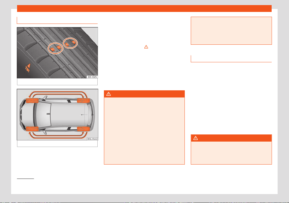
Practical tips
Tread wear indicators
Fig. 167
Tyre profile: tread wear indicators.
Fig. 168
Interchanging tyres.
Wear indicators around 1.6 mm high can be
f
ound on the base of the original t
yr
e treads,
ordered at regular intervals and running
across the tread
›››
Fig. 167. The letters "TWI"
or triangles on the sidewall of the tyre mark
the position of the wear indicators.
The minimum permitted profile depth
1)
have
been reached when the tyres have worn
down to the wear indicators. Replace the
tyres with new ones
›››
.
Changing wheel
s ar
ound
T
o ensure that the wear is equal on all tyres
the wheels should be changed round from
time to time according to the system
›››
Fig. 168. The useful life of all the tyres will
then be about the same time.
WARNING
The tyres must be replaced at the latest
when the tread is worn do
wn to the tread
wear indicators. Failure to follow this in-
struction could result in an accident.
●
Particularly in difficult driving conditions
such as wet or icy roads. It is important that
the tyre tread be as deep as possible and
be approximately the same on the tyres of
both the front and the rear axles.
●
The scant driving safety due to insuffi-
cient tread depth is particularly evident in
vehicle handling, when there is a risk of
“aquaplaning” in deep puddles of water
and when driving through corners, and
braking is also adv
ersely affected.
●
The speed has to be adapted according-
ly, otherwise there is a risk of losing control
over the vehicle.
Wheel nuts
The wheel bolts are matched t
o the rims.
When installing different wheels (for instance
alloy wheels or wheels with winter tyres) it is
important to use the correct wheel bolts with
the right length and correctly shaped bolt
heads. This ensures that wheels are fitted se-
curely and that the brake system functions
correctly.
The wheel bolts must be clean and turn easi-
ly.
A special adapter is required to turn the anti-
theft wheel bolts*
›››
page 39.
WARNING
Wheel nuts should never be greased or
oiled.
●
Use only wheel bolts which belong t
o the
wheel.
1)
Follow the regulations of the country you are
driving in.
190
Wheels
●
If the prescribed tor
que of the wheel
bolts is too low, they could loosen whilst
the vehicle is in motion. Risk of accident! If
the tightening torque is too high, the wheel
bolts and threads can be damaged.
CAUTION
See
›
››
page 42to find out the recommen-
ded tightening torque for wheel nuts for
steel and alloy rims.
Winter tyres
–
Winter tyres must be fitted on all f
our
wheel
s.
–
Only use wint
er tyres that are approved for
your vehicle.
–
Please note that the maximum permissible
speed for winter tyres may be lower than
for summer tyres.
–
Also note that winter tyres are no longer ef-
fective when the tread is worn down.
–
After fitting the wheels you must always
check the tyre pressures. When doing so,
take into account the correct tyre pressures
listed on the rear of the front left door frame
›››
page 188.
In winter road conditions winter tyres will con-
siderably improve vehicle handling. The de-
sign of summer tyres (width, rubber com-
pound, tread pattern) gives less grip on ice
and snow. This applies particularly to vehicles
equipped with wide section tyres or with
high speed tyres (code letters H, V or Y on
the sidewall).
Only use winter tyres of the correct type ap-
proved for your vehicle. The sizes of these
tyres are specified in the vehicle's documents
(e.g. EC Certificate of Conformity or COC
1)
).
The vehicle documentation varies depending
on the country of residence.
Winter tyres lose a great deal of their proper-
ties when the tread is worn down to a depth
of 4 mm.
The performance of winter tyres is also se-
verely impaired by ageing, even if the tread is
still much deeper than 4 mm.
A code letter indicating the speed limit is
stamped on all winter tyres
›››
page 187.
Vehicles capable of exceeding these speeds
must have an appropriate sticker attached
so that it is visible to the driver. Suitable stick-
ers are available from the SEAT Official Serv-
ice and specialised workshop. Please note
the regulations to this effect in your country.
“All-weather” tyres can also be used instead
of winter tyres.
Using winter tyres with V-rating
Please note that the generally applicable
240 km/h (149 mph) speed for winter tyres
with the letter V is subject to technical re-
strictions; the maximum permissible speed
for your vehicle may be significantly lower.
The maximum speed limit for these tyres de-
pends directly on the maximum axle weights
for your car and on the listed weight rating of
the tyres being used.
It is best to contact a SEAT Official Service to
check the maximum speed which is permissi-
ble for the V-rated tyres fitted on your car on
the basis of this information.
WARNING
Exceeding the maximum speed permitted
for the winter t
yres fitted on your car can
cause tyre failure, resulting in a loss of con-
trol of the vehicle – risk of accident.
For the sake of the environment
When winter is over, change back to sum-
mer tyres at an appr
opriate moment. In
temperatures above +7°C (+45°F), perform-
ance will be improved if summer tyres are
»
1)
COC = certificate of conformit
y.
191

Practical tips
used. Rolling noise, wear and energy con-
sumption will all be reduced.
Snow chains
Snow chains should only be used on the
front wheels
.
●
Check that they are correctly seated after
driving for a few yards; correct the position if
necessary, in accordance with the manufac-
turer's fitting instructions.
●
Keep your speed below 50 km/h (30 mph).
Snow chains will impro
ve braking ability as
well as traction in winter conditions.
For technical reasons snow chains may only
be used with the following wheel rim/tyre
combination.
165/70 R14
Chains with links of maximum 15 mm
175/65 R14
Remove any central wheel trims and the rim
ring bef
or
e fitting sno
w chains.
WARNING
The use of unsuitable or incorrectly fitted
chains could lead t
o serious accidents and
damage.
●
Always the appropriate snow chains.
●
Observe the fitting instructions pro
vided
by the snow chain manufacturer.
●
Never exceed the maximum permitted
speeds when driving with snow chains.
CAUTION
●
R
emov
e the snow chains to drive on
roads without snow. Otherwise they will im-
pair vehicle handling, damage the tyres
and wear out very quickly.
●
Wheel rims may be damaged or scratch-
ed if the chains come into direct contact
with them. SEAT recommends the use of
covered snow chains.
Tyre pressure monitor sys-
t
em*
Contr
ol l
amp
It lights up
The tyre pressure of a wheel is much lower than the
value set by the driver
›
››
in Tyre pressure moni-
tor system* on page 193.
Several control and warning lamps light up
f
or a f
e
w seconds when the ignition is switch-
ed on while the function is verified. They will
switch off after a few seconds.
WARNING
Observe the safety warnings
›››
in Con-
trol and warning l
amps on page 66.
Tyre pressure monitor system*
Fig. 169
In the glove box: tyre pressure loss in-
dicat
or butt
on.
The tyre pressure loss indicator compares the
r
e
v
olutions and thus the wheel diameter of
each wheel using the ESC. If the wheel diam-
eter of a wheel changes, the control indicator
of the tyres informs of this fact . The wheel
diameter changes when:
●
Tyre pressure is insufficient.
●
The tyre structure is damaged.
●
The vehicle is unbalanced because of a
load.
192
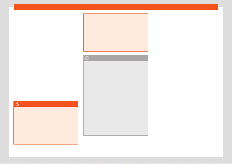
Wheels
●
The wheel
s of one axl
e ar
e under more
pressure (for example, driving with a trailer or
on steep slopes).
●
The vehicle is fitted with snow chains.
●
The temporary spare wheel is fitted.
●
The wheel on one axle is changed.
Tyre pressure setting
On adjusting tyre pressure or changing one
or more wheels, the
›››
Fig. 169 button must
be kept pressed down, with the ignition on,
until an acoustic signal is heard.
If the wheels are under excessive load (for ex-
ample, driving with a trailer or heavy load),
the tyre pressure must be increased to the
recommended value for a full load (see the
sticker
›››
Fig. 166). If the tyre monitor system
button is pressed down, the new tyre pres-
sures are confirmed.
WARNING
When the tyres are inflated at different
pressures or at a pr
essure that is too low
then a tyre may be damaged resulting in a
loss of control of the vehicle and a serious
or fatal accident.
●
If the lamp lights up, reduce speed im-
mediately and avoid any sudden turning or
braking manoeuvre. Stop when possible,
and check the tyre pressure and status.
●
The tyre monit
oring system can only op-
erate correctly if all of the tyres are infla-
ted to the correct pressure when cold.
●
If a tyre has not been punctured and it
does not have to be changed immediately,
drive to the nearest specialised workshop
at a moderate speed and have the tyre
checked and inflated to the correct pres-
sure.
Note
●
Driving f
or the first time with new t
yres at
a high speed can cause them to slightly ex-
pand, which could then produce an air
pressure warning.
●
Do not only rely on the tyre monitoring
system. Regularly check your tyres to en-
sure that the tyre pressure is correct and
that the tyres are not damaged due to
puncture, cuts, tears and impacts/dents.
Remove objects from the tyres only when
they have not pierced the tyres.
●
The tyre monitoring indicator does not
function when there is a fault in the ESC or
ABS
›››
page 153.
●
If the battery is disconnected, the yellow
warning lamp lights up after turning the
ignition on. This should turn off after a brief
journey.
193
Maintenance
Maintenance
SEAT Maint
enance Pr
o-
gr
amme
Service intervals
Service work and the Digital Main-
tenance Plan
Log of services performed (“Digital Main-
t
enance Pl
an”)
The SEAT deal
ership or a specialised work-
shop records Service receipts in a central
system. Thanks to this comprehensive docu-
mentation of the service history, it is possible
to reproduce the services performed any
time. SEAT recommends requesting a Service
receipt after every service carried out con-
taining all the services carried out on the sys-
tem.
Whenever there is a new service the receipt is
replaced with a current one.
The Digital Maintenance Plan is not avail-
able in some markets. In this case, your
SEAT dealer will inform you about the cur-
rent documentation of the work.
Service works
In the Digital Maintenance Plan, your SEAT
authorised service or specialised workshop
documents the following information:
●
When each one of the services was carried
out.
●
Whether a specific repair has been sugges-
ted, e.g. changing the brake pads in the near
future.
●
If you have expressed a special request for
the maintenance. Your Service Advisor will
write the work order.
●
The components or fluids that were
changed.
●
The date of the next service.
The Long Life Mobility Warranty is valid until
the next inspection. This information is docu-
mented in all checks performed.
The type and the volume of the service may
vary from one vehicle to another. A special-
ised workshop will be able to provide specific
information on the jobs for your vehicle.
WARNING
If the services are insufficient or not per-
formed and if the service interv
als are not
observed, the vehicle may be immobilised
in traffic cause an accident and severe in-
juries.
●
Make sure that any r
epairs are carried
out by a SEAT authorised service or speci-
alised workshop.
CAUTION
SEAT cannot be held liable for any damage
t
o the vehicl
e due to insufficient work or of
lack of availability of spare parts.
Note
Regular services on the vehicle not only
maintain its value
, but also its correct oper-
ation and road safety. For this reason, con-
duct the services in accordance with SEAT
guidelines.
Set Service Intervals
Service interval display
At SEAT
, the dat
es of the services ar
e indica-
ted by the service intervals display of the in-
strument panel
›››
page 63 .
The service intervals display informs of the
dates of the services. When it is time to per-
form the corresponding service, other neces-
sary additional work may also be done, such
as changing the brake fluid.
194

SEAT Maintenance Programme
Information about the terms of use
The service intervals and groups are usually
based on normal conditions of use.
If, on the other hand, the vehicl
e is under ad-
verse conditions of use, some of the work
must be carried out before the next service
period or even between service intervals.
Conditions of use adverse include:
●
Using the vehicle in areas with thick dust.
●
Using the vehicle mostly in situations with a
lot of traffic and st
ops (e.g. in a city).
●
Using the vehicle mostly in winter.
This applies especially for the following
parts (depending on equipment):
●
Dust and pollen filter
●
Air Care allergen filter
The Service Advisor of your specialised
workshop will gladly inform you about the
need of performing service work between
normal service intervals, always considering
the conditions of use of your vehicle.
Additional service offers
Approved spare parts
Original SEAT Spare Parts have been con-
ceived for their v
ehicles and approved by
SEAT, with a special emphasis on safety.
These parts correspond exactly to the manu-
facturer's requirements in terms of design,
accuracy of the measurements and materi-
als. The original SEAT Spare Parts have been
conceived exclusively for your vehicle. For this
reason, we always recommend the use of
Original SEAT Spare Parts. SEAT cannot be
held liable for the safety and suitability of
parts from other manufacturers.
Approved spare parts
The approved exchange parts, following the
manuf
act
ur
er's instructions, constitute anoth-
er service available to you, offering the possi-
bility of replacing complete sets, among
which the best known are: control units, elec-
trical elements, etc.
These parts are, approved parts, and are the
same as the factory parts, which are also ap-
proved spare parts.
Original accessories
We recommend you only use SEAT Original
Accessories and SEAT approv
ed accessories
for your vehicle. The reliability, safety and
suitability of these accessories have been in-
spected specifically for this type of vehicle.
SEAT cannot be held liable for the safety and
suitability of parts from other manufacturers.
SEAT Service Mobility
Since the moment you purchase your SEAT
v
ehicl
e you will be abl
e to enjoy the benefits
and coverage of the SEAT Mobility Service.
For the first two years after the purchase,
your new SEAT vehicle is automatically cov-
ered by the SEAT Mobility Service without ad-
ditional costs.
If you wish to enjoy this service after this peri-
od, you can extend SEAT Mobility as long as
you carry out the recommended Inspection
and Maintenance Services at a SEAT Author-
ised Service.
If your SEAT vehicle is immobilised due to a
fault or an accident, our assistance services
will help you keep moving.
Take into account that the SEAT Mobility
Service differs depending on the country in
which the vehicle was purchased. For further
»
195
Maintenance
information ask your SEAT dealership or the
SEAT w
ebsit
e in your country.
W
arranty
Fault-free operation warranty
SEAT Authorised Services ensure the perfect
condition of new vehicl
es. Check the pur-
chase agreement or complementary addi-
tional documentation provided by your Tech-
nical Service to see the conditions and the
terms of the warranty. Consult further infor-
mation in this regard in your SEAT Official
Service.
Commercial warranty for the high-
voltage batt
ery of electric and hy-
brid vehicles of SEAT S.A.
1. Compl
ementing the aforementioned war-
r
anties, the sell
er SEAT dealer grants the
high-voltage batteries of the vehicles that it
has sold an 8-year or 160,000-km warranty,
whichever comes first, for any material or fin-
ish defect.
2. The reduction of the battery’s capacity
over time is conditioned by the component it-
self and does not represent a defect from a
warranty point of view, provided said capaci-
ty is not below 70% of the useful capacity be-
fore 8 years or 160,000 km have passed,
whichever comes first.
3. The warranty for high-voltage batteries will
be invalidated when the defect is due to use,
handling or maintenance not in accordance
with the content of the instruction manual.
This is particularly applicable the battery
charge.
4. In addition, except for the duration of the
warranty, all conditions relating to the legal
warranty of the SEAT dealer (requirements,
criteria for assessing the absence of defects,
exclusion grounds, processing of entitlements
to benefits, entry into force, start and scope
of the warranty validity period, etc.) shall ap-
ply in relation to the high-voltage battery.
Vehicle maintenance
Maint
enance and cl
eaning
Basic observ
ations
Regular and careful care helps to maintain
the value of your vehicl
e. In addition, it may
become a prerequisite to demand the war-
ranty in the event of corrosion damage and
deficiencies in the paint coat of the body-
work.
Specialised workshops have the necessary
care products. Please follow the instructions
for application on the packaging.
WARNING
●
Cleaning products and other mat
erials
used for car care can be damaging to your
health if misused.
●
Always keep care products in a safe
place, out of the reach of children. Danger
of poisoning!
For the sake of the environment
●
When purchasing car care pr
oducts,
chose products that are compatible with
the environment.
●
The waste from car-care products should
not be disposed of with ordinary household
waste.
196
Vehicle maintenance
Washing the vehicle
The longer you take to clean the tanks, e.g.
remains of insects, bird e
xcrements, tree resin
or anti frost salt adhered to your vehicle, the
more damage it can cause to the surface.
High temperatures, for instance strong sun-
light, further intensify the damage.
Before washing the car, soften the dirt using
plenty of water.
To remove encrusted dirt such as insects, bird
droppings or tree resin, use a lot of water and
a microfibre cloth.
Have the underside of the vehicle washed af-
ter the end of the anti frost salts in winter.
High pressure cleaning equipment
When washing the vehicle with a high-pres-
sure cleaner, always follow the operating in-
structions for the equipment. This applies
particularly to the operating pressure and the
distance between the spraying water. Do not
point the jet directly towards the side win-
dows, doors or covers; the same applies for
the tyres, rubber hoses, damping material,
sensors* or camera lenses*. Keep a distance
of at least 40 cm.
Do not remove snow and ice with a high-
pressure cleaner.
Do not use a nozzle that sprays the water out
in a direct stream or one that has a r
otating
jet for forcing off dirt.
The water temperature must not exceed
60°C.
Automatic car washes
Spray the vehicle before starting the car
wash.
Make sure that the windows are closed and
the windscreen wipers are deactivated. Bear
in mind the instructions of the car wash tunnel
operator, especially if your vehicle has de-
tachable parts.
Use of car washes without brushes if possible.
Washing by hand
Clean your vehicle from top to bottom with a
soft sponge or with a brush. Only use clean-
ing products that do not contain solvents.
Washing vehicles with a matte paint by
hand
To prevent damage to the vehicle when
washing it, first remove the thicker dust and
dirt. To remove traces of insects, grease and
fingerprints, it is best to use a special cleaner
for matte paint.
Apply the product with a microfibre cloth. To
avoid damaging the surface of the paint, do
not apply too much pressure.
Rinse with plenty of water. Then clean it with
a neutral cleaning product and a soft microfi-
bre cloth.
Rinse the vehicle again with plenty of water
and then leave it to dry. Remove traces of
water with a leather cloth.
WARNING
●
Only wash the vehicl
e with the ignition
switched off or according to the specifica-
tions of the car wash tunnel operator. Risk
of accident!
●
When cleaning the underbody or the in-
side of the wheel arches, protect yourself
from sharp or pointy metal parts. Risk of
cut!
●
After cleaning the brakes could act more
slowly due to moisture or, in winter, the ice
on the brake discs and pads. Risk of acci-
dent! In this case the brakes should be
dried by pressing the brake pedal several
times.
CAUTION
●
Before w
ashing the vehicle in an auto-
matic car wash, please make sure to re-
tract the exterior mirrors to prevent them
from being damaged. The electric folding*
exterior mirrors should only be folded elec-
trically!
●
Do not wash the vehicle in direct sunlight.
Risk of damaging the paint job!
»
197
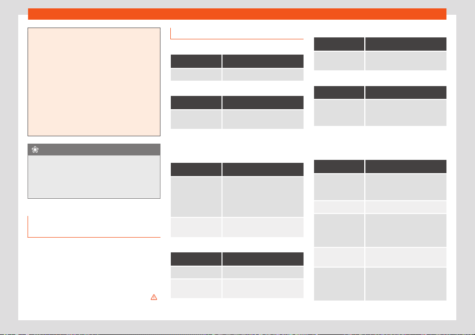
Maintenance
●
Do not use sponges, abrasive househol
d
sponges or similar to clean insect remains.
Risk of damaging the surface!
●
Vehicle parts with matte paint:
–
Do not use polish or hard wax. Risk of
damaging the surface!
–
Never select washing programmes that
include the use of wax. This could dam-
age the appearance of matte paint.
–
Do not put stickers or magnets on parts
with matte paint, as removing them
may damage the paint.
For the sake of the environment
The car should only be washed in special
wash bays. These places ar
e designed to
prevent the water that is used for washing,
which may be contaminated, from entering
the drains.
Cleaning and maintenance instruc-
tions
The cleaning and maintenance of individual
components of the v
ehicl
e can be check
ed in
the following tables. The contents should be
understood merely as a recommendation. Go
to your specialised workshop if you have spe-
cial questions or parts that are not listed. Take
he general considerations into account
›››
in Take special care with... on page 201.
Cleaning the exterior
Windscreen wipers
Problem Solution
Dirt Soft cloth with wipers
Headlights / Tail lights
Problem Solution
Dirt Soft sponge with neutral soap
solution
a)
a)
Neutral soap solution: two tablespoons maximum in
1 litr
e of w
at
er
Sensors / Camera lenses
Problem Solution
Dirt
Sensors: soft cloth with a sol-
v
ent-free cleaning product
Camera lenses: soft cloth with
an alcohol-free cleaning prod-
uct
Snow/ice
Hand brush/Anti frost spray
with no solvents
Wheels
Problem Solution
Antifreeze salt Water
Brake abrasion
dust
Acid-free special cleaning
product
End exhausts
Problem Solution
Antifreeze salt Water, if a steel cleaning prod-
uct is required
Covers / Trims
Problem Solution
Dirt Neutral soap solution
a)
, if a
steel cleaning pr
oduct is re-
quired
a)
Neutral soap solution: two tablespoons maximum in
1 litr
e of w
at
er
Paint
Problem Solution
Paint flaws
Check the paint's colour code
in an authorised service and re-
stor
e with a touch-up pencil
Spilled fuel Immediately rinse with water
Environmental rust
tank
Apply rust remo
ver and then
apply hard wax. Go you your
specialised w
orkshop if you
have any queries
Corrosion
Have your specialised work-
shop take car
e of this
The water does
not create dr
op-
lets on the clean
paint
Maintain with hard wax (at
least 2 times a year)
198
Vehicle maintenance
Problem Solution
No shine de-
spite sober main-
tenance/paint
Treat with suitable wax and ap-
ply paint preservativ
e after-
wards if the wax used does not
contain preservative ingredi-
ents
Tanks, e.g. insect
remains, bird
dr
oppings, tree
sap, road salt
Immediately soften with water
and remove with a microfibre
cloth
Fat-based dirt,
e.g. cosmetic
products or
sunscr
een
Delete immediately with a neu-
tral soap solution
a)
and a soft
cloth
a)
Neutral soap solution: two tablespoons maximum in
1 litr
e of w
at
er
Carbon fibre parts
Problem Solution
Dirt Clean the same way as pain-
ted parts
››
›
page 197
Decoration slides
Problem Solution
Dirt Soft sponge with neutral soap
solution
a)
a)
Neutral soap solution: two tablespoons maximum in
1 litr
e of w
at
er
Interior cleaning
Windows
Problem Solution
Dirt Apply windscreen cleaner and
then dry with a cloth
Covers / Trims
Problem Solution
Dirt Neutral soap solution
a)
a)
Neutral soap solution: two tablespoons maximum in
1 litr
e of w
at
er
Plastic parts
Problem Solution
Dirt Damp cloth
Encrusted dirt Neutral soap solution
a)
, if pos-
sible solvent-free plastic clean-
er
a)
Neutral soap solution: two tablespoons maximum in
1 litr
e of w
at
er
Displays/instrument panel
Problem Solution
Dirt Soft cloth with a liquid crystal
display cleaner
Control panels
Problem Solution
Dirt Soft brush, then soft cloth with
neutral soap solution
a)
a)
Neutral soap solution: two tablespoons maximum in
1 litre of wat
er
Seat belts
Problem Solution
Dirt Neutral soap solution
a)
, al-
lo
wed to dry before retracting
a)
Neutral soap solution: two tablespoons maximum in
1 litr
e of w
at
er
Fabrics, artificial, Alcantara leather
Problem Solution
Particles of dirt
stuck to surf
aces
Vacuum cleaner
Water-based dirt,
e.g. coffee
, tea,
blood etc.
Absorbent cloth and neutral
soap solution
a)
Grease-based
dirt, e.g. oil, mak
e-
up, etc.
Apply a neutral soap solution
a)
.
Absorb the dissolved grease
and paint particles drying with
an absorbent cloth, in case you
must treat it with water after-
wards
»
199

Maintenance
Problem Solution
Special dirt, e.g.
pens, nail polish,
dispersion paint,
shoe cream etc.
Special st
ain remove: dry with
an absorbent cloth, if applica-
ble, apply neutral soap solution
afterwards
a)
a)
Neutral soap solution: two tablespoons maximum in
1 litre of wat
er
Natural leather
Problem Solution
Recent dirt Cotton cloth with neutral soap
solution
a)
Water-based dirt,
e.g. coffee
, tea,
blood etc.
Recent stains: absorbent cloth
Dry stains: stain remover suita-
ble for leather
Grease-based
dirt, e.g. oil, mak
e-
up, etc.
Recent stains: absorbent cloth
and suitable stain remover for
leather
Dry stains: grease solvent
spray
Special dirt, e.g.
pens, nail polish,
dispersion paint,
shoe cream etc.
St
ain remover suitable for
leather
Care Apply preservative cream regu-
larly to protect from sunlight.
Use a colour preservative if re-
quired
a)
Neutral soap solution: two tablespoons maximum in
1 litr
e of w
at
er
Carbon fibre parts
Problem Solution
Dirt Clean like plastic parts
Take special care with...
Headlights/tail lights
●
Do not clean the headlights/tail lights with
a dry cloth or sponge.
●
Do not use cl
eaning products that contain
alcohol. Risk of cracks!
Wheel
s
●
Do not use for paint wax or other abrasive
products.
●
If the protective coating on the paint of the
rim has been damaged due to stone impacts,
scratches, etc., the damage should be re-
paired immediately.
Camera lenses
●
Do not use hot or warm water to remove ice
or snow from the camera lenses. Risk of
cracking the lens!
●
To clean the camera lens, never use abra-
sive cleaning products or products with alco-
hol. Risk of scratches and cracks!
Windows
●
Remove snow and ice from windows and
exterior mirrors with a plastic scraper only. To
avoid scratches, the scraper should only be
pushed in one direction and not moved to
and fro.
●
Never remove snow or ice from windows
and rearview mirrors with warm or hot water.
Risk of cracks on the windows!
●
To prevent damage to the heating of the
rear window, do not put stickers over the
heating elements.
Covers/trims
●
Do not use cleaning products or chrome
based cleaning agents.
Paint
●
The vehicle must be free from dirt and dust
before applying wax or care products. Risk of
scratches!
●
Do not apply wax or care products if the
vehicle is exposed to direct sunlight. Risk of
damaging the paint job!
●
The ambient rust deposits must not be re-
moved through friction. Risk of damaging the
paint job!
●
Remove cosmetic products and sunlight
immediately. Risk of damaging the paint job!
200
Vehicle maintenance
Displays/instrument panel
●
The displays, the instrument panel and the
trim ar
ound it must not be cl
eaned dry. Risk of
scr
atches!
●
Make sure that the instrument panel is
switched off and cooled down before clean-
ing.
●
Make sure that no liquid leaks between the
instrument panel and the trim. Risk of dam-
age!
Control panels
●
Make sure that no liquid leaks into the con-
trol panels. Risk of damage!
Seat belts
●
Do not remove the seat belts to clean them.
●
Seat belts and their components must nev-
er be cleaned with chemical products, nor
should they be allowed to come into contact
with corrosive liquids, solvents or sharp ob-
jects. Risk of damaging the fabric!
●
If you find any damage to the belt webbing,
belt fittings, the belt retractor or the buckle,
ask your specialised workshop to replace the
belt in question.
Fabrics/artificial leather/Alcantara leath-
er
●
Do not treat artificial leather/Alcantara
leather with leather cleaning products, sol-
vents, wax polish, shoe cream, stain removers
or similar products.
●
If the stain is very hard to remove, take the
vehicle to a specialised workshop to have it
removed there. This will prevent damage.
●
Do not use steam cleaners, brushes, hard
sponges, etc. to clean.
●
Do not turn on seat heating* to dry the
seats.
●
Sharp objects on clothing, such as zips, riv-
ets or belts can damage the surface.
●
Open Velcro, e.g. on clothes can damage
the seat upholstery. Make sure that Velcro
fasteners are closed.
Natural leather
●
Never use solvents, wax polish, shoe cream,
spot removers or similar products on leather.
●
Sharp objects on clothing, such as zips, riv-
ets or belts can damage the surface.
●
Do not use steam cleaners, brushes, hard
sponges, etc. to clean.
●
Do not turn on seat heating* to dry the
seats.
●
Avoid exposing leather to direct sunlight for
long periods, otherwise it may tend to lose
some of its colour. If the car is left for a pro-
longed period in the bright sun, it is best to
cover the leather.
WARNING
Do not use water-repellent coatings on the
windscreen. In bad visibility conditions
such as humid weather, darkness or when
the sun is in its low
est point, visibility may
be impacted. Risk of accident! Such coat-
ings can also cause the windscreen wiper
blades to make noise.
Note
●
R
emains of insects can be remo
ved much
more easily with previously treated paint.
●
Regular car care treatments can prevent
deposits of ambient rust.
Remove the vehicle from traffic
If you want to leave your vehicle stationary
f
or a l
ong period of time
, contact a qualified
workshop. They will gladly inform you about
the necessary measures, such as anti-corro-
sion protection, Service and storage.
Also bear in mind the indications regarding
the vehicle’s batteries.
201
Maintenance
Accessories and modifi-
cations t
o the v
ehicl
e
Accessories, spare parts and
repair work
Introduction
Always ask your dealer or specialist retailer
for advice befor
e purchasing accessories
and replacement parts.
Your vehicle is designed to offer a high stand-
ard of active and passive safety. For this rea-
son, we recommend that you ask a SEAT Offi-
cial Service for advice before fitting accesso-
ries or replacement parts. Your SEAT Official
Service has the latest information from the
manufacturer and can recommend accesso-
ries and replacement parts which are suita-
ble for your requirements. They can also an-
swer any questions you might have regarding
official regulations.
We recommend only using SEAT accesso-
ries and genuine SEAT parts®. SEAT has
tested these parts and accessories for suita-
bility, reliability and safety. SEAT Official
Services have the necessary experience and
facilities to ensure that the parts are installed
correctly and professionally.
Any retro-fitted equipment which has a di-
rect eff
ect on the vehicle and/or the way it is
driven, such as a cruise control system or
electronically-controlled suspension, must
be approved for use in your vehicle and bear
the e mark (the European Union's authorisa-
tion symbol).
If any additional electrical devices are fit-
ted which do not serve to control the vehicle
itself (for instance a refrigerator box, laptop
or ventilator fan, etc.), they must bear the
sign (manufacturer conformity declaration in
the European Union).
WARNING
Accessories, for example telephone hold-
ers or cup holders, should ne
ver be fitted
on the covers, or within the working range
of the airbags. Otherwise, there is a danger
of injury if the airbag is triggered in an acci-
dent.
Technical modifications
Unauthorised modifications to the electronic
components, softw
ar
e
, wiring or data transfer
in the vehicle may cause malfunctioning.
You will appreciate that your SEAT dealership
cannot be held liable for any damage
caused by modifications and/or work per-
formed incorrectly.
For this reason we recommend asking official
SEAT service centres to do any necessary
work using genuine SEAT parts®.
WARNING
Incorrectly performed modifications or
other work on your vehicl
e can lead to mal-
functions and cause accidents.
Radio telephones and office equip-
ment
Radio transmitters (fixed installation)
Any r
etr
ofit inst
allations of radio transmitters
in the vehicle require prior approval. SEAT
generally authorises in-vehicle installations
of approved types of radio transmitters provi-
ded that:
●
The antenna is installed correctly.
●
The aerial is installed on the exterior of the
vehicle (and shielded cables are used to-
gether with non-reflective aerial trimming).
●
The effective transmitting power does not
exceed 10 Watts at the aerial base.
A SEAT Official Service and specialised work-
shop will be able to inform you about options
for installing and operating radio transmitters
with a higher transmitting power.
202
Accessories and modifications to the vehicle
Mobile radio transmitters
Commer
cial mobil
e t
elephones or radio
equipment might interfere with the electron-
ics of your vehicle and cause malfunctions.
This may be due to:
●
No external aerial.
●
External aerial incorrectly installed.
●
Transmitting power more than 10 W.
You must, therefore, do not operate portable
mobile telephones or radio equipment inside
the vehicle without a properly installed exter-
nal aerial
›››
.
Pl
ease not
e al
so that the maximum range of
the equipment can only be achieved with an
external aerial.
Business equipment
Retrofit installation of business or private
equipment in the vehicle is permitted, provi-
ded the equipment cannot interfere with the
driver's immediate control of the vehicle and
that any such equipment carries the mark.
Any retrofit equipment that could influence
the driver's control of the vehicle must have a
type approval for your vehicle and must carry
the e mark.
WARNING
Mobile telephones or radio equipment
which is operated inside the v
ehicle without
a properly installed external aerial can
create e
xcessive magnetic fields that
could cause a health hazard.
Note
●
The post
erior fitting of electric and el
ec-
tronic equipment in this vehicle affects its
licence and could lead to the withdrawal of
the vehicle registration document under
certain circumstances.
●
Please use the mobile telephone/radio
operating instructions.
203

Information for the user
Information for the user
Inf
ormation f
or the user
Inf
ormation stored by the
control units
Description and operation
Your vehicle is fitted with a series of electronic
control units that, among others, are r
espon-
sible for the engine management. In addition,
the control units monitor the proper function-
ing of the airbags.
Therefore, while the vehicle is being driven,
these electronic control units are continuous-
ly analysing the vehicle data. In the event of
faults or deviations from the theoretical val-
ues, only this data is stored. Normally, the
warning lamps on the instrument panel light
up in the event of faults.
This data can only be read and analysed us-
ing special equipment.
The storing of the data allows specialised
workshops to detect and repair faults. Stored
data may include:
●
Data referring to the engine
●
Speed
●
Direction of travel
●
Braking for
ce
●
Detection of seat belt
The vehicle control units never record conver-
sations held by passengers in the vehicle.
In vehicles equipped with an emergency call
function via the mobile phone or other appli-
ances connected in the vehicle, it is possible
to send the vehicle position. If the control unit
records an accident with airbag activation,
the system may automatically send a signal.
This will depend on the network operator.
Normally, transmission is only possible in
areas with good coverage.
Event Data Recorder
The vehicle is not fitted with an event data re-
corder.
An event data recorder temporarily stores the
vehicle information. Therefore, in the event of
an accident, it is possible to obtain detailed
information about how the accident occur-
red. Vehicles with airbag systems can store
data relating to impact speed, seat belt sta-
tus, seat positions and airbag activation times
may be stored, etc. The volume of data de-
pends on the manufacturer.
Event data recorders can only be mounted
with authorisation from the vehicle owner
and, in some countries, they are governed by
local legislation.
Reprogramming of control units
On the whole, all the data required for the
component management is stored in the
control units. The programming of certain
convenience functions, such as the turn sig-
nals, individual door opening and instructions
on the display can be modified using special
equipment at the workshop. If the comfort
functions are reprogrammed, the information
and Instruction Manual descriptions will not
coincide with the modified functions. There-
fore, SEAT recommends that any modifica-
tions be recorded in the section “Other work-
shop notes” in the Maintenance Programme.
The SEAT Official Service must have a record
of any modification to the programming.
Reading the vehicle's fault memory
There is a diagnostics connector in the vehi-
cle interior for reading the vehicle fault mem-
ory. The fault memory documents errors and
deviations from the theoretical values of the
electronic control units.
The diagnostics connector is in the driver side
footwell area, next to the lever for opening
the bonnet, below a cover.
The fault memory should only be read and
reset by a specialised workshop.
204

Information for the user
Other important information
Envir
onment
al compatibilit
y
Environmental protection is a top priority in
the design, choice of materials and manuf
ac-
ture of your new SEAT.
Constructive measures to encourage re-
cycling
●
Joints and connections designed for easy
dismantling.
●
Modular construction to facilitate disman-
tling.
●
Increased use of single-grade materials.
●
Plastic parts and elastomers are marked in
accordance with ISO 1043, ISO 11469 and
ISO 1629.
Choice of mat
erials
●
Use of recycled materials.
●
Use of compatible plastics in the same part
if its components are not easily separated.
●
Use of recycled materials and/or materials
originating from renewable sources.
●
Reduction of volatile components, including
odour, in plastic materials.
●
Use of CFC-free coolants.
Ban on heavy metals, with the exceptions
dictated by law (Annex II of ELV Directive
2000/53/EC): cadmium, lead, mercury,
hexavalent chromium.
Manufacturing methods
●
Reduction of the quantity of thinner in the
protective wax for cavities.
●
Use of plastic film as protection during vehi-
cle transport.
●
Use of solvent-free stickers.
●
Use of CFC-free coolants in cooling sys-
tems.
●
Recycling and energy recovery from resi-
dues (RDF).
●
Improvement in the quality of waste water.
●
Use of systems for the recovery of residual
heat (thermal recovery, enthalpy wheels,
etc.).
●
The use of water-soluble paints.
Stickers and plates
Some parts in the engine compartment come
fr
om the f
act
ory with certificates of safety, la-
bels or plates containing important informa-
tion regarding the operation of the vehicle, for
example, on the battery charging socket flap,
on the passenger's sun visor, on the driver
door strut, or on the floor of the luggage
compartment.
●
Never remove these certificates of safety,
labels or plates, and ensure they are kept in
good condition and are legible.
●
If a vehicle part, bearing a certificate of
safety, label or plate, is replaced, the special-
ised workshop should attach the information
back in the same place.
Certificate of safety
A certificate of safety on the door strut states
that all the safety standards and regulations
established by the national traffic authorities
responsible for road safety were met at the
time of manufacture. It may also give the
month and year of manufacture, together
with the chassis number.
Warning of high voltage label
There is a label close to the bonnet lock
which warns of high voltage in the vehicle's
electrical system.
Using the vehicle in other countries
and continents
The vehicle is manufactured at the factory for
use in a particul
ar country in accor
dance
with the national l
egislation in force at the
time of manufacture.
If the vehicle is sold in another country or
used in another country for an extended
»
205
Information for the user
period of time, the applicable legislation of
that country shoul
d be observ
ed.
It may be necessary t
o fit or remove certain
pieces of equipment or to deactivate certain
functions. Service work may also be affected.
This is particularly true if the vehicle is used in
a different climate for an extended period of
time.
CAUTION
●
SEAT does not accept liability for any
damage t
o the vehicle due to an inade-
quate service or the non-availability of
genuine spare parts.
●
SEAT does not accept liability if the vehi-
cle does not comply in part or in full with
the legal requirements of other countries or
continents.
Radio and antenna reception
For factory-fitted radio equipment, the aerial
f
or r
adio r
eception is fitted to the roof of the
vehicle.
Note
If electrical equipment such as mobile tele-
phones, is used near a roof aerial, you may
observe int
erference in the reception of AM
stations.
Information about SEAT repairs
WARNING
Repairs or modifications which are not per-
formed correctly may r
esult in damage or
errors in the vehicle operation, affecting
the effectiveness of the driver assist and
airbag systems. This could result in serious
accident.
●
Have any repairs or modifications carried
out at a specialised workshop.
Declaration of conformity
The respective manufacturer hereby de-
cl
ar
es that the pr
oducts indicated below
comply with basic requirements and the fol-
lowing provisions and important legislation on
the date of manufacture of the vehicle,
among others FCC Part 15.19, FCC Part 15.21
and RSS-Gen Issue 1:
Radio frequency equipment
●
Electronic gearbox lock.
●
Vehicle key
Electrical equipment
●
12 volt power socket
Collection of end-of-life vehicles
and scrapping
Collection of end-of-life vehicles
SEAT is already prepar
ed for the moment
when you wish to scrap your vehicle and of-
fers you an environmentally-friendly solution.
An extensive network of used car reception
centres already exists in much of Europe. Af-
ter the vehicle has been delivered, you will re-
ceive a certificate of destruction describing
the environmentally friendly scrapping of the
vehicle in accordance with applicable legis-
lation.
We will collect the used vehicle free of
charge, provided it complies with all national
legislation.
Please see your technical service for further
information about the collection and scrap-
ping of end-of-life vehicles.
Scrapping
The relevant safety requirements must be ob-
served when the vehicle or components of
the airbag or belt tensioner systems are
scrapped. These requirements are known to
specialised workshops.
206

Information for the user
Recycling of electrical or electron-
ic de
vices
All electrical or electronic devices (EED) that
are not permanently fitted in the v
ehicle must
be marked with the following symbol:
This symbol indicates that EED must not be
discarded as home waste but through selec-
tive waste collection.
Information about the EU Di-
rective 2014/53/EU
Simplified EU compliance decl
ara-
tion
Your vehicle has different radioelectrical devi-
ces. The manuf
act
ur
ers of these devices de-
clare that they comply with Directive
2014/53/EU when legally required.
The full text of the EU compliance declaration
is available online at the following address:
www.seat.com/generalinfo
Addresses of the manufacturers
According to the Directive 2014/53/EU, all
rele
vant components must include the ad-
dress of the manufacturer.
The address of the manufacturers of compo-
nents that, due to their size or nature, cannot
include a sticker are listed below, as long as it
is legally required:
Radioelectrical
equipment fitted
in the vehicl
e
Addresses of the
manufacturers
Radiofrequency remote
control key
Dell
a KGaA Hueck & Co.
Rixbecker Straße 75
59552 Lippst
adt,
GERMANY
Radio frequency re-
mote control (auxiliary
heat
er)
Transmitted-Receiver
(independent heating)
Digades GmbH
Äußere Weberstr
aße 20
02763 Zittau, GERMANY
Webasto Thermo &
Comfort SE
Friedrichshafener Str
. 9
82205 Gilching, GERMANY
Radar sensors for as-
sistance systems
ADC Aut
omotive Distance
Control Systems GmbH
P
eter-Dornier-Straße 10
88131 Lindau, GERMANY
Robert Bosch GmbH
Postfach 16 61
71226 Leonberg,
GERMANY
207

Information for the user
Frequency bands, station power
Radioelectrical equipment
a)
Frequency band Max. station power Valid for models
Radiofrequency remote control (vehicle)
433.05-434.78 MHz 10 mW (ERP)
All SEAT models
433.05-434.79 MHz 10 mW
868.0-868.6 MHz 25 mW
434.42 MHz 32 µW
Radio frequency remote control (auxiliary
heater)
868.7-869.2 MHz (869.0 MHz) 25 mW Leon, Ateca and Tarraco
868.0-868.6 MHz (868.3 MHz) 3.1 mW Alhambra
Transmitted-Receiver (independent heating)
868.0-868.6 MHz (868.3 MHz) 23.5 mW Alhambra
868.7-869.2 MHz (869.0 MHz) 23.5 mW Leon, Ateca and Tarraco
Bluetooth
2402-2480 MHz 6 dBm
All SEAT models
2400-2483.5 MHz 10 dBm
Connection to the external antenna of the car
GSM 900: 880-915 MHz 33 dBm
Leon, Ateca, Alhambra and TarracoGSM 1800: 1710-1785 MHz 30 dBm
WCDMA FDD I: 1920-1980 MHz 24 dBm
WCDMA FDD lll: 1710-1785 MHz 21 dBm
Tarraco and Leon
WCDMA FDD VIII: 880-915MHz 21 dBm
LTE FDD1: 1920-1980 MHz 23 dBm
LTE FDD3: 1710-1785 MHz 23 dBm
LTE FDD7: 2500-2570 MHz 23 dBm
LTE FDD8: 880-915 MHz 23 dBm
LTE FFD20: 832-862 MHz 23 dBm
208

Information for the user
Radioelectrical equipment
a)
Frequency band Max. station power Valid for models
Wireless hotspot 2400-2483.5 MHz 10 dBm Leon, Ateca and Tarraco
Keyless Access 434.42 MHz 32 µW Ibiza, Arona, Leon, Ateca and Tarraco
Radar sensors for assistance systems
76 GHz-77 GHz
28.2 dBm Leon and Alhambra
35.0 dBm Ibiza, Arona, Ateca and Tarraco
24050-24250 MHz 20 dBm Arona, Ateca, Tarraco and Alhambra
Wireless charging
110-120 kHz 10 W Ibiza, Arona, Leon, Ateca and Tarraco
111-120 kHz 10 W New Leon
Instrument panel 125 kHz 40 dBµA/m
Ibiza, Arona, Ateca, Tarraco and
Alhambr
a
Online Connectivity Unit
EGSM900: 880-915 MHz 33 dBm
Ibiz
a, Arona, Leon, Ateca and Tarraco
DCS1800: 1710-1785 MHz 31 dBm
UMTS FDD 1: 1920-1980 MHz 24 dBm
UMTS FDD 3: 1710-1785 MHz 24 dBm
UMTS FDD 8: 880-915 MHz 24 dBm
E-UTRA FDD 1: 1920-1980 MHz 23.5 dBm
E-UTRA FDD 3: 1710-1785 MHz 23.0 dBm
E-UTRA FDD 7: 2500-2570 MHz 23.5 dBm
E-UTRA FDD 8: 880-915 MHz 23.0 dBm
E-UTRA FDD 20: 832-862 MHz 23.5 dBm
E-UTRA FDD 28: 703-748 MHz 23.0 dBm
a)
The commissioning or authorisation of radioelectrical technology may be restricted in some European countries, forbidden or only allowed with additional requirements.
»
209

Information for the user
Hereby, Molex CVS Dabendorf GmbH de-
cl
ar
es that the r
adio equipment type LTE-
MBC-EU2 is in compliance with Directive
2014/53/EU. The full text of the EU declara-
tion of conformity is available at the following
internet address:
http://www.molex.com/doc
210
Indications about the technical data
Technical data
Indications about the
t
echnical dat
a
Impor
tant information
Introduction
The values indicated in the technical data
may diff
er depending on optional equipment
or v
ersion of the model, as w
ell as in the case
of special vehicles and equipment for certain
countries.
The information in the official vehicle docu-
mentation takes precedence at all times.
Abbreviations used in the Technical Speci-
fications section
kW Kilowatt, engine power measurement.
PS
Horsepower (not currently used), en-
gine power measur
ement unit.
rpm, 1/min Revolutions per minute - engine speed.
Nm Newton metres, unit of engine torque.
Vehicle identification data
Vehicle identification number
The vehicle identification number (v
ehicle ID
number) can be read from the outside of the
vehicle through a window located on the
windscreen. This viewer is located in the low-
er part of the windscreen. The vehicle identifi-
cation number (chassis number) is also stam-
ped on the right water drain channel. The wa-
ter drain channel is located between the sus-
pension tower and the wing. Open the bonnet
to read the vehicle identification number .
Type plate
The type plate is located on the vehicle’s right
hand door frame. Vehicles for certain export
countries do not have a type plate.
Filling capacities
Capacity of the windscreen washer fluid con-
t
ainer
Windscreen washer
fluid container
appro
x. 3 litres
Weights
Load on the roof
The maximum authorised load on the roof of
your v
ehicle is 50 kg.
Empty weight, total weight, axle loads
The empty weight of the vehicle with driver
(75 kg) was calculated according to the (EU)
1230/2012 standard. Optional equipment can
increase the empty weight, which means that
the possible useful load decreases propor-
tionally.
WARNING
The values indicated for the maximum per-
mitted weights must not be e
xceeded.
There is a risk of accident and damage!
211

Technical data
Engine specifications
Electric engine
Power kW (CV) 61 (82)
Maximum torque (Nm) 210
Gearbox automatic
Top speed (km/h) 130
Acceleration from 0-100 km/h (seconds) 12.3
Maximum authorised weight (kg) 1,530
212
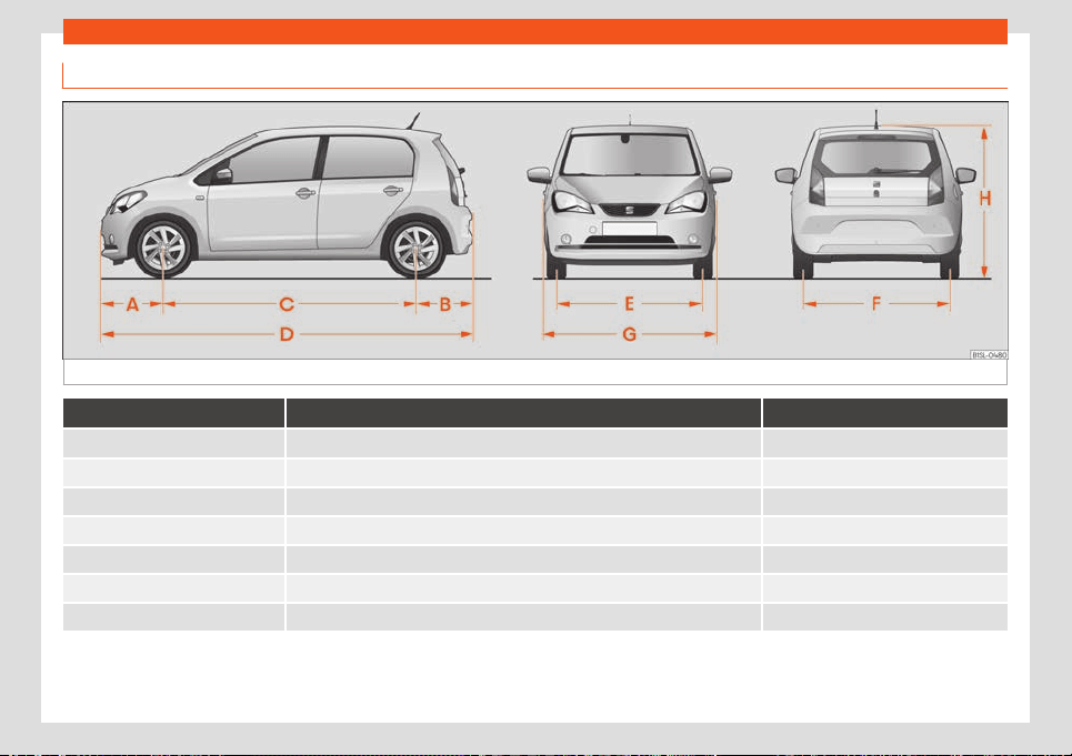
Indications about the technical data
Dimensions.
Fig. 170 Dimensions.
Mii
A/B Front and rear projection (mm) 595/542
C Wheelbase (mm) 2,420
D Length (mm) 3,557
E/F Front/rear
a)
track width (mm) 1,428/1,4
24
G Width (mm) 1,645
H Height at kerb weight (mm) 1,478
Turning radius (m) approx. 9.8
a)
This data will change depending on the type of wheel rim. Values for wheel 185/70 R14 ET38.
213


Index
Index
Numbers and Symbol
s
12-v
olt batt
ery
assisted start . . . . . . . . . . . . . . . . . . . . . . . . . . . . . . . 44
charging . . . . . . . . . . . . . . . . . . . . . . . . . . . . . . . . . . 184
disconnect and connect . . . . . . . . . . . . . . 182, 184
electrolyte level . . . . . . . . . . . . . . . . . . . . . . . . . . . 183
location . . . . . . . . . . . . . . . . . . . . . . . . . . . . . . . . . . . 182
replacement . . . . . . . . . . . . . . . . . . . . . . . . . . . . . . 184
winter operations . . . . . . . . . . . . . . . . . . . . . . . . . . 182
A
ABS
see Anti-lock brake system . . . . . . . . . . . . . . . . 153
Accessories . . . . . . . . . . . . . . . . . . . . . . . . . . . . . . . . . 202
Adjust
front seats . . . . . . . . . . . . . . . . . . . . . . . . . . . . . . . . . 86
lights . . . . . . . . . . . . . . . . . . . . . . . . . . . . . . . . . . . . . . . 80
seats . . . . . . . . . . . . . . . . . . . . . . . . . . . . . . . . . . . . . . . . 11
Adjusting the seat belt . . . . . . . . . . . . . . . . . . . . . . . . 18
Airbags . . . . . . . . . . . . . . . . . . . . . . . . . . . . . . . . . . . . . . . 20
description . . . . . . . . . . . . . . . . . . . . . . . . . . . . . . . . . 20
Airbag system . . . . . . . . . . . . . . . . . . . . . . . . . . . . . . . . 20
activation . . . . . . . . . . . . . . . . . . . . . . . . . . . . . . . . . . . 21
control lamp . . . . . . . . . . . . . . . . . . . . . . . . . . . . . . . . 22
deactivation of the front airbag . . . . . . . . . . . . . 23
description . . . . . . . . . . . . . . . . . . . . . . . . . . . . . . . . . 20
front airbags . . . . . . . . . . . . . . . . . . . . . . . . . . . . . . . 22
how it works . . . . . . . . . . . . . . . . . . . . . . . . . . . . . . . . 21
Air conditioning
Climatronic . . . . . . . . . . . . . . . . . . . . . . . . . . . . . . . . 101
usage instructions . . . . . . . . . . . . . . . . . . . . . . . . . 102
Air recirculation . . . . . . . . . . . . . . . . . . . . . . . . . . . . . . 103
Air vents . . . . . . . . . . . . . . . . . . . . . . . . . . . . . . . . . . . . . 102
Alternator
warning lamp . . . . . . . . . . . . . . . . . . . . . . . . . . . . . 185
Ambient lighting . . . . . . . . . . . . . . . . . . . . . . . . . . . . . . 81
Antenna . . . . . . . . . . . . . . . . . . . . . . . . . . . . . . . . . . . . 206
Anti-lock brake system . . . . . . . . . . . . . . . . . . . . . . 153
Anti-puncture . . . . . . . . . . . . . . . . . . . . . . . . . . . . . 35, 36
Anti-puncture kit . . . . . . . . . . . . . . . . . . . . . . . . . . 34, 35
check after 10 minutes . . . . . . . . . . . . . . . . . . . . . . 37
components . . . . . . . . . . . . . . . . . . . . . . . . . . . . . . . 36
inflating the tyre . . . . . . . . . . . . . . . . . . . . . . . . . . . . 36
sealing the tyre . . . . . . . . . . . . . . . . . . . . . . . . . . . . . 36
Anti-puncture set . . . . . . . . . . . . . . . . . . . . . . . . . . . . . 35
Antifreeze . . . . . . . . . . . . . . . . . . . . . . . . . . . . . . . . . . . . 178
Aspects to think about before starting the ve-
hicle . . . . . . . . . . . . . . . . . . . . . . . . . . . . . . . . . . . . . . . . 10
ASR
see Traction control system . . . . . . . . . . . . . . . 153
Assistance systems
cruise control . . . . . . . . . . . . . . . . . . . . . . . . . . . . . 146
optical parking system (OPS) . . . . . . . . . . . . . 156
parking aid . . . . . . . . . . . . . . . . . . . . . . . . . . . . . . . . 156
parking distance warning . . . . . . . . . . . . . . . . . 156
Tyre pressure monitoring . . . . . . . . . . . . . . . . . . 192
Assisted start . . . . . . . . . . . . . . . . . . . . . . . . . . . . . . . . . 44
Audible warning
control and warning lamps . . . . . . . . . . . . . . . . . 65
lights . . . . . . . . . . . . . . . . . . . . . . . . . . . . . . . . . . . . . . . 76
unbuckled seat belt . . . . . . . . . . . . . . . . . . . . . . . . . 14
Auto Lock (central locking) . . . . . . . . . . . . . . . . . . . 70
Automatic car wash . . . . . . . . . . . . . . . . . . . . . . . . . 197
Automatic dipped beam headlight control . . . . 77
Automatic gearbox . . . . . . . . . . . . . . . . . . . . . . . . . . 140
control lamp . . . . . . . . . . . . . . . . . . . . . . . . . . . . . . 140
driving tips . . . . . . . . . . . . . . . . . . . . . . . . . . . . . . . . . 142
ignition key extraction lock . . . . . . . . . . . . . . . . 135
selector lever lock . . . . . . . . . . . . . . . . . . . . . . . . . 141
selector lever positions . . . . . . . . . . . . . . . . . . . . 140
AUX-IN . . . . . . . . . . . . . . . . . . . . . . . . . . . . . . . . . . . . . . . 124
AUX-IN multimedia socket . . . . . . . . . . . . . . . . . . . 124
B
Backrest of the rear seat
folding . . . . . . . . . . . . . . . . . . . . . . . . . . . . . . . . . . . . . 88
raise . . . . . . . . . . . . . . . . . . . . . . . . . . . . . . . . . . . . . . . 88
Bag hooks . . . . . . . . . . . . . . . . . . . . . . . . . . . . . . . . 92, 96
Bag support . . . . . . . . . . . . . . . . . . . . . . . . . . . . . . . . . . 95
Battery . . . . . . . . . . . . . . . . . . . . . . . . . . . . . . . . . . . . . . . 68
Before starting the vehicle . . . . . . . . . . . . . . . . . . . . 10
Belt tightening . . . . . . . . . . . . . . . . . . . . . . . . . . . . . . . . 19
Blown bulbs
change a bulb . . . . . . . . . . . . . . . . . . . . . . . . . . . . . 49
Bluetooth . . . . . . . . . . . . . . . . . . . . . . . . . . . . . . . . . . . . 123
Bonnet . . . . . . . . . . . . . . . . . . . . . . . . . . . . . . . . . . . . . . . 176
opening and closing . . . . . . . . . . . . . . . . . . . . . . . 177
Brake fluid . . . . . . . . . . . . . . . . . . . . . . . . . . . . . . . . . . . 180
Brakes . . . . . . . . . . . . . . . . . . . . . . . . . . . . . . . . . . . . . . . 150
brake fluid . . . . . . . . . . . . . . . . . . . . . . . . . . . . . . . . . 180
brake servo . . . . . . . . . . . . . . . . . . . . . . . . . . . . . . . 150
braking assistant . . . . . . . . . . . . . . . . . . . . . . . . . . 153
handbrake . . . . . . . . . . . . . . . . . . . . . . . . . . . . . . . . . 152
new brake pads . . . . . . . . . . . . . . . . . . . . . . . . . . . 150
Braking assistant . . . . . . . . . . . . . . . . . . . . . . . . . . . . 153
Braking system
warning lamp . . . . . . . . . . . . . . . . . . . . . . . . . . . . . 150
215

Index
C
Camer
a
L
ane Assist . . . . . . . . . . . . . . . . . . . . . . . . . . . . . . . .
148
Capacities
window washer water . . . . . . . . . . . . . . . . . . . . . . 181
Central locking . . . . . . . . . . . . . . . . . . . . . . . . . . . . . . . 69
central locking switch . . . . . . . . . . . . . . . . . . . . . . . 71
emergency lock . . . . . . . . . . . . . . . . . . . . . . . . . . . . 72
remote control key . . . . . . . . . . . . . . . . . . . . . . . . . 70
selective unlocking system . . . . . . . . . . . . . . . . . 70
Change a bulb . . . . . . . . . . . . . . . . . . . . . . . . . . . . . . . 49
front bumper . . . . . . . . . . . . . . . . . . . . . . . . . . . . . . . . 51
headlights . . . . . . . . . . . . . . . . . . . . . . . . . . . . . . . . . 50
number plate light . . . . . . . . . . . . . . . . . . . . . . . . . . 52
side turn signal . . . . . . . . . . . . . . . . . . . . . . . . . . . . . 53
tail lights . . . . . . . . . . . . . . . . . . . . . . . . . . . . . . . . . . . . 51
Change the wiper blades . . . . . . . . . . . . . . . . . . . . 43
Changing a wheel . . . . . . . . . . . . . . . . . . . . . . . . . . . . 38
subsequent work . . . . . . . . . . . . . . . . . . . . . . . . . . . 42
wheel nuts . . . . . . . . . . . . . . . . . . . . . . . . . . . . . . . . . 39
Changing parts . . . . . . . . . . . . . . . . . . . . . . . . . . . . . 202
Charging cable . . . . . . . . . . . . . . . . . . . . . . . . . . . . . 170
for charging stations (AC) . . . . . . . . . . . . . . . . . . 171
for sockets . . . . . . . . . . . . . . . . . . . . . . . . . . . . . . . . . 172
Charging the high-voltage battery . . . . . . . . . . 160
at a charging station (DC) . . . . . . . . . . . . . . . . . 165
charging process display . . . . . . . . . . . . . . . . . . 168
emergency release of the charging con-
nector . . . . . . . . . . . . . . . . . . . . . . . . . . . . . . . . . . . 169
from a socket or a charging station (AC) . . 164
home charging (wallbox) . . . . . . . . . . . . . . . . . . 166
immediate charging and programmed
charging . . . . . . . . . . . . . . . . . . . . . . . . . . . . . . . . 167
problems and solutions . . . . . . . . . . . . . . . . . . . 169
Childproof locks
electric windows . . . . . . . . . . . . . . . . . . . . . . . . . . . 75
Child seats
group classification . . . . . . . . . . . . . . . . . . . . . . . . . 27
ISOFIX system . . . . . . . . . . . . . . . . . . . . . . . . . . . . . . 30
safety instructions . . . . . . . . . . . . . . . . . . . . . . . . . . 28
securing with the seat belt . . . . . . . . . . . . . . . . . 33
Top Tether system . . . . . . . . . . . . . . . . . . . . . . 30, 32
Cleaning the vehicle
Alcantara . . . . . . . . . . . . . . . . . . . . . . . . . . . . . . . . . 199
carbon fibre . . . . . . . . . . . . . . . . . . . . . . . . . 199, 200
control panels . . . . . . . . . . . . . . . . . . . . . . . . . . . . . 199
covers/ trims . . . . . . . . . . . . . . . . . . . . . . . . . 198, 199
decorative sheets . . . . . . . . . . . . . . . . . . . . . . . . . 199
end exhausts . . . . . . . . . . . . . . . . . . . . . . . . . . . . . . 198
exterior . . . . . . . . . . . . . . . . . . . . . . . . . . . . . . . . . . . . 198
fabrics . . . . . . . . . . . . . . . . . . . . . . . . . . . . . . . . . . . . 199
headlights/tail light units . . . . . . . . . . . . . . . . . . 198
high pressure cleaning equipment . . . . . . . . . 197
interior . . . . . . . . . . . . . . . . . . . . . . . . . . . . . . . . . . . . 199
leather . . . . . . . . . . . . . . . . . . . . . . . . . . . . . . . . . . . 200
paint . . . . . . . . . . . . . . . . . . . . . . . . . . . . . . . . . . . . . . 198
plastic parts . . . . . . . . . . . . . . . . . . . . . . . . . . . . . . . 199
radio screen . . . . . . . . . . . . . . . . . . . . . . . . . . . . . . . 199
seat belts . . . . . . . . . . . . . . . . . . . . . . . . . . . . . . . . . 199
sensors / camera lenses . . . . . . . . . . . . . . . . . . 198
special care . . . . . . . . . . . . . . . . . . . . . . . . . . . . . . 200
wash the vehicle . . . . . . . . . . . . . . . . . . . . . . . . . . . 197
wheels . . . . . . . . . . . . . . . . . . . . . . . . . . . . . . . . . . . . 198
windows . . . . . . . . . . . . . . . . . . . . . . . . . . . . . . . . . . 199
wiper blades . . . . . . . . . . . . . . . . . . . . . . . . . . . . . . 198
Climatronic . . . . . . . . . . . . . . . . . . . . . . . . . . . . . . . . . . 101
Closing . . . . . . . . . . . . . . . . . . . . . . . . . . . . . . . . . . . . . . 69
bonnet . . . . . . . . . . . . . . . . . . . . . . . . . . . . . . . . . . . . . 177
luggage compartment . . . . . . . . . . . . . . . . . . . . . 74
windows . . . . . . . . . . . . . . . . . . . . . . . . . . . . . . . . . . . . 75
Coming Home . . . . . . . . . . . . . . . . . . . . . . . . . . . . . . . . 79
Connectivity . . . . . . . . . . . . . . . . . . . . . . . . . . . . . . . . . 129
Contact . . . . . . . . . . . . . . . . . . . . . . . . . . . . . . . . . . . . . 135
Control and warning lamps . . . . . . . . . . . . . . . . . . 65
airbags . . . . . . . . . . . . . . . . . . . . . . . . . . . . . . . . . . . . . 23
airbag system . . . . . . . . . . . . . . . . . . . . . . . . . . . . . . 22
alternator . . . . . . . . . . . . . . . . . . . . . . . . . . . . . . . . . 185
anti-lock brake system ABS . . . . . . . . . . . . . . . . 152
ASR . . . . . . . . . . . . . . . . . . . . . . . . . . . . . . . . . . . . . . . . 152
audible warning . . . . . . . . . . . . . . . . . . . . . . . . . . . . 65
braking system . . . . . . . . . . . . . . . . . . . . . . . . . . . . 150
cooling system . . . . . . . . . . . . . . . . . . . . . . . . . . . . 178
cruise control (GRA) . . . . . . . . . . . . . . . . . . . . . . . 146
drive system . . . . . . . . . . . . . . . . . . . . . . . . . . . . . . . 135
EDL . . . . . . . . . . . . . . . . . . . . . . . . . . . . . . . . . . . . . . . . 152
electromechanical steering . . . . . . . . . . . . . . . 144
ESC . . . . . . . . . . . . . . . . . . . . . . . . . . . . . . . . . . . . . . . 152
high-voltage battery . . . . . . . . . . . . . . . . . . . . . . 160
Lane Assist . . . . . . . . . . . . . . . . . . . . . . . . . . . . . . . . 148
lights . . . . . . . . . . . . . . . . . . . . . . . . . . . . . . . . . . . . . . . 76
replacement . . . . . . . . . . . . . . . . . . . . . . . . . . . . . . 140
seat belt . . . . . . . . . . . . . . . . . . . . . . . . . . . . . . . . . . . . 14
steering column lock . . . . . . . . . . . . . . . . . . . . . . 144
tyre pressure loss indicator . . . . . . . . . . . . . . . . 192
Controls and displays
overview . . . . . . . . . . . . . . . . . . . . . . . . . . . . . . . . . . . 55
Control units . . . . . . . . . . . . . . . . . . . . . . . . . . . . . . . . 204
reprogramming . . . . . . . . . . . . . . . . . . . . . . . . . . . 204
216

Index
Cooling system
check the cool
ant . . . . . . . . . . . . . . . . . . . . . . . . .
1
79
control lamps . . . . . . . . . . . . . . . . . . . . . . . . . . . . . . 178
refilling coolant . . . . . . . . . . . . . . . . . . . . . . . . . . . . 179
Correct driver position . . . . . . . . . . . . . . . . . . . . . . . . 11
Cruise control . . . . . . . . . . . . . . . . . . . . . . . . . . . . . . . 146
control and warning lamp . . . . . . . . . . . . . . . . . 146
operation . . . . . . . . . . . . . . . . . . . . . . . . . . . . . . . . . . 147
Cybersecurity . . . . . . . . . . . . . . . . . . . . . . . . . . . . . . . 129
D
DAB . . . . . . . . . . . . . . . . . . . . . . . . . . . . . . . . . . . . . . . . . . 118
main menu . . . . . . . . . . . . . . . . . . . . . . . . . . . . . . . . . 119
station update . . . . . . . . . . . . . . . . . . . . . . . . . . . . . 120
Dangers of not using the seat belt . . . . . . . . . . . . 16
Data logger . . . . . . . . . . . . . . . . . . . . . . . . . . . . . . . . . 204
Data transmissions . . . . . . . . . . . . . . . . . . . . . . . . . . 129
Deactivation of the front airbag . . . . . . . . . . . . . . 23
Declaration of conformity . . . . . . . . . . . . . . . . . . . 206
Diagnostic connector . . . . . . . . . . . . . . . . . . . . . . . 204
Digital clock . . . . . . . . . . . . . . . . . . . . . . . . . . . . . . . . . . 57
Digital radio
see DAB . . . . . . . . . . . . . . . . . . . . . . . . . . . . . . . . . . . . 118
Disposal
airbag system . . . . . . . . . . . . . . . . . . . . . . . . . . . . 206
seat belt tensioners . . . . . . . . . . . . . . . . . . . . . . . . . 19
vehicle at the end of its useful life . . . . . . . . . 206
Door handle
interior . . . . . . . . . . . . . . . . . . . . . . . . . . . . . . . . . . . . . 55
Doors . . . . . . . . . . . . . . . . . . . . . . . . . . . . . . . . . . . . . . . . . 72
child lock . . . . . . . . . . . . . . . . . . . . . . . . . . . . . . . . . . . 73
Drink holder . . . . . . . . . . . . . . . . . . . . . . . . . . . . . . . . . . 96
bottle holder . . . . . . . . . . . . . . . . . . . . . . . . . . . . . . . 96
centre console . . . . . . . . . . . . . . . . . . . . . . . . . . . . . 97
Driver . . . . . . . . . . . . . . . . . . . . . . . . . . . . . . . . . . . . . . . . . 11
Drive system
automatic connection . . . . . . . . . . . . . . . . . . . . . 138
automatic disconnection . . . . . . . . . . . . . . . . . . 138
brake energy recuperation . . . . . . . . . . . . . . . . 134
connecting . . . . . . . . . . . . . . . . . . . . . . . . . . . . . . . . 136
control lamp . . . . . . . . . . . . . . . . . . . . . . . . . . . . . . . 135
disconnecting . . . . . . . . . . . . . . . . . . . . . . . . . . . . . 137
functions . . . . . . . . . . . . . . . . . . . . . . . . . . . . . . . . . . 133
problems and solutions . . . . . . . . . . . . . . . . . . . . 139
starting . . . . . . . . . . . . . . . . . . . . . . . . . . . . . . . . . . . . 135
Driving
data storage . . . . . . . . . . . . . . . . . . . . . . . . . . . . . . 204
driving on flooded roads . . . . . . . . . . . . . . . . . . . 145
parking on inclines . . . . . . . . . . . . . . . . . . . . . . . . 154
park on upward slopes . . . . . . . . . . . . . . . . . . . . 154
safe . . . . . . . . . . . . . . . . . . . . . . . . . . . . . . . . . . . . . . . . 10
trips abroad . . . . . . . . . . . . . . . . . . . . . . . . . . . . 81, 146
Driving data . . . . . . . . . . . . . . . . . . . . . . . . . . . . . . . . . . 61
Driving data indicator . . . . . . . . . . . . . . . . . . . . . . . . . 61
Driving on flooded roads . . . . . . . . . . . . . . . . . . . . 145
Driving profiles . . . . . . . . . . . . . . . . . . . . . . . . . . . . . . 144
Duplicate keys . . . . . . . . . . . . . . . . . . . . . . . . . . . . . . . 67
Dust and pollen filter . . . . . . . . . . . . . . . . . . . . . . . . 100
Dynamic headlight range control . . . . . . . . . . . . 80
E
EDL
see Electronic differential lock . . . . . . . . . . . . . 153
Electric devices . . . . . . . . . . . . . . . . . . . . . . . . . . . . . . . 97
Electric range . . . . . . . . . . . . . . . . . . . . . . . . . . . . . . . 163
Electric windows . . . . . . . . . . . . . . . . . . . . . . . . . . . . . . 75
Electrolyte . . . . . . . . . . . . . . . . . . . . . . . . . . . . . . . . . . . 183
Electromechanical steering
control lamp . . . . . . . . . . . . . . . . . . . . . . . . . . . . . . 144
lamp . . . . . . . . . . . . . . . . . . . . . . . . . . . . . . . . . . . . . . 143
steering column lock . . . . . . . . . . . . . . . . . . . . . . 143
Electronic differential lock . . . . . . . . . . . . . . . . . . . 153
Electronic immobilizer . . . . . . . . . . . . . . . . . . . . . . . 139
Electronic self-locking . . . . . . . . . . . . . . . . . . . . . . . 153
Electronic Stability Control (ESC) . . . . . . . . . . . . 153
Emergencies . . . . . . . . . . . . . . . . . . . . . . . . . . . . . . . . . 34
anti-puncture kit . . . . . . . . . . . . . . . . . . . . . . . . . . . . 35
changing a wheel . . . . . . . . . . . . . . . . . . . . . . . . . . 38
changing the battery . . . . . . . . . . . . . . . . . . . . . . 184
fire extinguishers . . . . . . . . . . . . . . . . . . . . . . . . . . . 34
first aid kit . . . . . . . . . . . . . . . . . . . . . . . . . . . . . . . . . . 34
hazard warning lights . . . . . . . . . . . . . . . . . . . . . . 80
jump leads . . . . . . . . . . . . . . . . . . . . . . . . . . . . . . . . . 44
replace a blown fuse . . . . . . . . . . . . . . . . . . . . . . . 48
vehicle tool kit . . . . . . . . . . . . . . . . . . . . . . . . . . . . . . 34
warning triangle . . . . . . . . . . . . . . . . . . . . . . . . . . . . 34
Emergency closing and opening
front passenger door . . . . . . . . . . . . . . . . . . . . . . . 72
rear lid . . . . . . . . . . . . . . . . . . . . . . . . . . . . . . . . . . . . . 75
Emergency locking of the front passenger
door . . . . . . . . . . . . . . . . . . . . . . . . . . . . . . . . . . . . . . . . 72
Emergency opening
rear lid . . . . . . . . . . . . . . . . . . . . . . . . . . . . . . . . . . . . . 75
Emergency release of the charging connec-
tor . . . . . . . . . . . . . . . . . . . . . . . . . . . . . . . . . . . . . . . . . 169
energy recuperation . . . . . . . . . . . . . . . . . . . . . . . . . 134
Engine
assisted start . . . . . . . . . . . . . . . . . . . . . . . . . . . . . . . 44
running in . . . . . . . . . . . . . . . . . . . . . . . . . . . . . . . . . . 145
217

Index
Engine compartment
batt
ery . . . . . . . . . . . . . . . . . . . . . . . . . . . . . . . . . . . .
182
br
ake fluid . . . . . . . . . . . . . . . . . . . . . . . . . . . . . . . . . 180
coolant . . . . . . . . . . . . . . . . . . . . . . . . . . . . . . . 178, 179
opening and closing . . . . . . . . . . . . . . . . . . . . . . . 177
safety instructions . . . . . . . . . . . . . . . . . . . . . . . . . 176
safety warnings . . . . . . . . . . . . . . . . . . . . . . . . . . . . 174
window washer tank . . . . . . . . . . . . . . . . . . . . . . . 181
working in the engine compartment . . . . . . . 176
Engine coolant . . . . . . . . . . . . . . . . . . . . . . . . . . . . . . 178
check the level . . . . . . . . . . . . . . . . . . . . . . . . . . . . 179
G 12 plus-plus . . . . . . . . . . . . . . . . . . . . . . . . . . . . . 178
G 13 . . . . . . . . . . . . . . . . . . . . . . . . . . . . . . . . . . . . . . . 178
specifications . . . . . . . . . . . . . . . . . . . . . . . . . . . . . 178
Engine specifications . . . . . . . . . . . . . . . . . . . . . . . . 212
Enlarge
the luggage compartment . . . . . . . . . . . . . . . . . 88
Environment
environmental compatibility . . . . . . . . . . . . . . 205
Equipment . . . . . . . . . . . . . . . . . . . . . . . . . . . . . . . . . . 202
ESC (electronic stability control) . . . . . . . . . . . . 153
Event data recorder . . . . . . . . . . . . . . . . . . . . . . . . . 204
Event Data Recorder . . . . . . . . . . . . . . . . . . . . . . . . 204
Exterior lighting
change a bulb . . . . . . . . . . . . . . . . . . . . . . . . . . . . . 49
Exterior mirrors
fold manually . . . . . . . . . . . . . . . . . . . . . . . . . . . . . . 85
settings . . . . . . . . . . . . . . . . . . . . . . . . . . . . . . . . . . . . 85
Exterior view . . . . . . . . . . . . . . . . . . . . . . . . . . . . . . . . . . . 7
External antenna . . . . . . . . . . . . . . . . . . . . . . . . . . . . 202
Extinguisher . . . . . . . . . . . . . . . . . . . . . . . . . . . . . . . . . . 34
F
Fabrics: clean . . . . . . . . . . . . . . . . . . . . . . . . . . . . . . . 199
Factors that have a negative influence on
safe driving . . . . . . . . . . . . . . . . . . . . . . . . . . . . . . . . . 10
Fastening rings . . . . . . . . . . . . . . . . . . . . . . . . . . . . . . . . 91
Fault memory
connector . . . . . . . . . . . . . . . . . . . . . . . . . . . . . . . . 204
reading . . . . . . . . . . . . . . . . . . . . . . . . . . . . . . . . . . . 204
Filling capacities
window washer tank . . . . . . . . . . . . . . . . . . . . . . . 211
First aid kit
housing . . . . . . . . . . . . . . . . . . . . . . . . . . . . . . . . . . . . 34
Front airbags . . . . . . . . . . . . . . . . . . . . . . . . . . . . . . . . . 22
control lamp . . . . . . . . . . . . . . . . . . . . . . . . . . . . . . . . 22
Full-LED headlights . . . . . . . . . . . . . . . . . . . . . . . . . . . 49
Fuses . . . . . . . . . . . . . . . . . . . . . . . . . . . . . . . . . . . . . . . . . 47
colour coded . . . . . . . . . . . . . . . . . . . . . . . . . . . . . . 48
fuse box . . . . . . . . . . . . . . . . . . . . . . . . . . . . . . . . 47, 48
preparations for replacing fuses . . . . . . . . . . . . 48
recognise blown fuses . . . . . . . . . . . . . . . . . . . . . 48
replace . . . . . . . . . . . . . . . . . . . . . . . . . . . . . . . . . . . . 48
G
Glove compartment . . . . . . . . . . . . . . . . . . . . . . . . . . 95
H
Handbrake . . . . . . . . . . . . . . . . . . . . . . . . . . . . . . . . . . 152
Hangers . . . . . . . . . . . . . . . . . . . . . . . . . . . . . . . . . . . . . . 96
Hazard warning lights . . . . . . . . . . . . . . . . . . . . . . . . 80
Head-on collisions and the laws of physics . . . 16
Head-protection airbags
safety instructions . . . . . . . . . . . . . . . . . . . . . . . . . . 25
Headlights
change a bulb . . . . . . . . . . . . . . . . . . . . . . . . . . . . . 49
headlight washer . . . . . . . . . . . . . . . . . . . . . . . . . . . 83
trips abroad . . . . . . . . . . . . . . . . . . . . . . . . . . . . . . . . 81
Headrest . . . . . . . . . . . . . . . . . . . . . . . . . . . . . . . . . . . . . 87
High-voltage battery
charging cable . . . . . . . . . . . . . . . . . . . . . . . . . . . . 170
control lamps . . . . . . . . . . . . . . . . . . . . . . . . . . . . . 160
fast charge (DC) . . . . . . . . . . . . . . . . . . . . . . . . . . 165
home charging (wallbox) . . . . . . . . . . . . . . . . . . 166
immediate charging and programmed
charging . . . . . . . . . . . . . . . . . . . . . . . . . . . . . . . . 167
loading . . . . . . . . . . . . . . . . . . . . . . . . . . . . . . . . . . . . 161
socket (AC) . . . . . . . . . . . . . . . . . . . . . . . . . . . . . . . 164
state of charge . . . . . . . . . . . . . . . . . . . . . . . . . . . . 163
warnings . . . . . . . . . . . . . . . . . . . . . . . . . . . . . . . . . . 158
Hill driving assistant . . . . . . . . . . . . . . . . . . . . . . . . . . 143
Horn . . . . . . . . . . . . . . . . . . . . . . . . . . . . . . . . . . . . . . . . . . 55
I
Ignition . . . . . . . . . . . . . . . . . . . . . . . . . . . . . . . . . . . . . . 135
Ignition key extraction lock . . . . . . . . . . . . . . . . . . . 135
Ignition lock . . . . . . . . . . . . . . . . . . . . . . . . . . . . . . . . . . 135
Information for the user . . . . . . . . . . . . . . . . . . . . . 204
Infotainment System . . . . . . . . . . . . . . . . . . . . . . . . . 107
adapting the playback volume . . . . . . . . . . . . 124
anti-theft password . . . . . . . . . . . . . . . . . . . . . . . . 111
AUX-IN connection . . . . . . . . . . . . . . . . . . . . . . . . 124
Bluetooth . . . . . . . . . . . . . . . . . . . . . . . . . . . . . . . . . . 123
calling by telephone . . . . . . . . . . . . . . . . . . . . . . . 127
changing station . . . . . . . . . . . . . . . . . . . . . . . . . . . 117
Drive Mii App . . . . . . . . . . . . . . . . . . . . . . . . . . . . . . 128
energy management . . . . . . . . . . . . . . . . . . . . . . . 111
frequency bands . . . . . . . . . . . . . . . . . . . . . . . . . . . 117
frequency change . . . . . . . . . . . . . . . . . . . . . . . . . 117
general operating information . . . . . . . . . . . . . . 111
Media . . . . . . . . . . . . . . . . . . . . . . . . . . . . . . . . . . . . . 120
overview of the unit . . . . . . . . . . . . . . . . . . . . . . . . 109
preset buttons . . . . . . . . . . . . . . . . . . . . . . . . . . . . . 118
218

Index
radio . . . . . . . . . . . . . . . . . . . . . . . . . . . . . . . . . . . . . . . 115
saf
et
y instructions . . . . . . . . . . . . . . . . . . . . . . . . .
107
saving stations . . . . . . . . . . . . . . . . . . . . . . . . . . . . . 118
SD card . . . . . . . . . . . . . . . . . . . . . . . . . . . . . . . . . . . 122
switching Media source . . . . . . . . . . . . . . . . . . . . 121
switching on and off . . . . . . . . . . . . . . . . . . . . . . . . 111
tuning station frequency . . . . . . . . . . . . . . . . . . . 117
USB . . . . . . . . . . . . . . . . . . . . . . . . . . . . . . . . . . . . . . . . 123
INFO (traffic announcement) . . . . . . . . . . . . . . . . . 116
Inspection . . . . . . . . . . . . . . . . . . . . . . . . . . . . . . . . . . . 194
Instrument panel . . . . . . . . . . . . . . . . . . . . . . . . . . 56, 57
control and warning lamps . . . . . . . . . . . . . . . . . 65
display . . . . . . . . . . . . . . . . . . . . . . . . . . . . . . . . . 57, 59
instruments . . . . . . . . . . . . . . . . . . . . . . . . . . . . . . . . . 57
service intervals display . . . . . . . . . . . . . . . . . . . . 63
use with the wiper lever . . . . . . . . . . . . . . . . . . . . 64
Instrument panel lighting . . . . . . . . . . . . . . . . . . . . . . 81
Interior mirror
anti-dazzle . . . . . . . . . . . . . . . . . . . . . . . . . . . . . . . . . 84
Interior view . . . . . . . . . . . . . . . . . . . . . . . . . . . . . . . . . . . . 9
Interlock button . . . . . . . . . . . . . . . . . . . . . . . . . . . . . . 141
ISOFIX . . . . . . . . . . . . . . . . . . . . . . . . . . . . . . . . . . . . . . . . 30
ISOFIX system . . . . . . . . . . . . . . . . . . . . . . . . . . . . . . . . 30
J
Jack . . . . . . . . . . . . . . . . . . . . . . . . . . . . . . . . . . . . . . . . . . 34
position points . . . . . . . . . . . . . . . . . . . . . . . . . . . . . 40
Jump leads . . . . . . . . . . . . . . . . . . . . . . . . . . . . . . . . . . 44
Jump start . . . . . . . . . . . . . . . . . . . . . . . . . . . . . . . . . . . 44
description . . . . . . . . . . . . . . . . . . . . . . . . . . . . . . . . . 45
K
Keys
assign a key . . . . . . . . . . . . . . . . . . . . . . . . . . . . . . . . 67
changing the battery . . . . . . . . . . . . . . . . . . . . . . . 68
duplicates . . . . . . . . . . . . . . . . . . . . . . . . . . . . . . . . . 68
mechanical key . . . . . . . . . . . . . . . . . . . . . . . . . . . . 68
remote control . . . . . . . . . . . . . . . . . . . . . . . . . . . . . 67
spare key . . . . . . . . . . . . . . . . . . . . . . . . . . . . . . . . . . . 67
synchronise . . . . . . . . . . . . . . . . . . . . . . . . . . . . . . . . 69
unlock and lock . . . . . . . . . . . . . . . . . . . . . . . . . . . . 70
vehicle key . . . . . . . . . . . . . . . . . . . . . . . . . . . . . . . . . 67
Key switch . . . . . . . . . . . . . . . . . . . . . . . . . . . . . . . . . . . . 23
L
Lane Assist . . . . . . . . . . . . . . . . . . . . . . . . . . . . . . . . . . 148
control and warning lamp . . . . . . . . . . . . . . . . . 148
Lane Assist system
see Lane Assist . . . . . . . . . . . . . . . . . . . . . . . . . . . . 148
Leather: clean . . . . . . . . . . . . . . . . . . . . . . . . . . . . . . . 199
Leaving Home . . . . . . . . . . . . . . . . . . . . . . . . . . . . . . . . 79
Legal provisions . . . . . . . . . . . . . . . . . . . . . . . . . . . . . . 131
Levels control . . . . . . . . . . . . . . . . . . . . . . . . . . . . . . . . 211
Lift the vehicle . . . . . . . . . . . . . . . . . . . . . . . . . . . . . . . . 40
Light range control . . . . . . . . . . . . . . . . . . . . . . . . . . . 80
Lights . . . . . . . . . . . . . . . . . . . . . . . . . . . . . . . . . . . . . . . . . 76
audible warnings . . . . . . . . . . . . . . . . . . . . . . . . . . . 76
AUTO . . . . . . . . . . . . . . . . . . . . . . . . . . . . . . . . . . . . . . . 77
change a bulb . . . . . . . . . . . . . . . . . . . . . . . . . . . . . 49
coming home . . . . . . . . . . . . . . . . . . . . . . . . . . . . . . 79
control and warning lamps . . . . . . . . . . . . . . . . . 76
control lighting . . . . . . . . . . . . . . . . . . . . . . . . . . . . . 81
controlling the lights . . . . . . . . . . . . . . . . . . . . . . . . 76
daylight . . . . . . . . . . . . . . . . . . . . . . . . . . . . . . . . . . . . 77
dipped beam headlights . . . . . . . . . . . . . . . . . . . 76
fog light . . . . . . . . . . . . . . . . . . . . . . . . . . . . . . . . . . . . 78
headlight range control . . . . . . . . . . . . . . . . . . . . 80
instrument lighting . . . . . . . . . . . . . . . . . . . . . . . . . . 81
interior lights . . . . . . . . . . . . . . . . . . . . . . . . . . . . . . . . 81
leaving home . . . . . . . . . . . . . . . . . . . . . . . . . . . . . . . 79
main beam headlights . . . . . . . . . . . . . . . . . . 76, 78
reading lights . . . . . . . . . . . . . . . . . . . . . . . . . . . . . . . 81
side lights . . . . . . . . . . . . . . . . . . . . . . . . . . . . . . . . . . 76
switch . . . . . . . . . . . . . . . . . . . . . . . . . . . . . . . . . . . . . . 77
switching on and off . . . . . . . . . . . . . . . . . . . . . . . . 77
turn signals . . . . . . . . . . . . . . . . . . . . . . . . . . . . . . . . . 78
Loading the luggage compartment
bag hooks . . . . . . . . . . . . . . . . . . . . . . . . . . . . . . . . . . 92
fastening rings . . . . . . . . . . . . . . . . . . . . . . . . . . . . . . 91
general advice . . . . . . . . . . . . . . . . . . . . . . . . . . . . . 89
luggage compartment . . . . . . . . . . . . . . . . . 74, 89
positioning the load . . . . . . . . . . . . . . . . . . . . . . . . 89
positioning the luggage . . . . . . . . . . . . . . . . . . . . 89
roof carrier system . . . . . . . . . . . . . . . . . . . . . . . . . 93
Load on the roof . . . . . . . . . . . . . . . . . . . . . . . . . . . . . . 93
technical data . . . . . . . . . . . . . . . . . . . . . . . . . . . . . 93
Lock and unlock
luggage compartment . . . . . . . . . . . . . . . . . . . . . 74
with the central locking switch. . . . . . . . . . . . . . . 71
Luggage compartment . . . . . . . . . . . . . . . . . . . 74, 89
closing . . . . . . . . . . . . . . . . . . . . . . . . . . . . . . . . . . . . . 74
emergency unlocking . . . . . . . . . . . . . . . . . . . . . . 75
luggage compartment lighting . . . . . . . . . . . . . 81
storing the rear shelf . . . . . . . . . . . . . . . . . . . . . . . 90
variable luggage compartment floor . . . . . . . 91
Luggage compartment floor . . . . . . . . . . . . . . . . . . 91
Luggage compartment shelf
storing . . . . . . . . . . . . . . . . . . . . . . . . . . . . . . . . . . . . . 90
Lumbar support . . . . . . . . . . . . . . . . . . . . . . . . . . . . . . 86
219

Index
M
Main beam headlight l
e
v
er . . . . . . . . . . . . . . . . . . . 78
Maintenance
see Service . . . . . . . . . . . . . . . . . . . . . . . . . . . . . . . . 194
Mats . . . . . . . . . . . . . . . . . . . . . . . . . . . . . . . . . . . . . . . . . . 13
Media . . . . . . . . . . . . . . . . . . . . . . . . . . . . . . . . . . . . . . . 120
External data storage device connected to
a USB port . . . . . . . . . . . . . . . . . . . . . . . . . . . . . . . 123
smartphone . . . . . . . . . . . . . . . . . . . . . . . . . . . . . . . 128
MFD
see Multifunction display . . . . . . . . . . . . . . . . . . . 61
Mirrors . . . . . . . . . . . . . . . . . . . . . . . . . . . . . . . . . . . . . . . 84
adjusting the exterior mirrors . . . . . . . . . . . . . . . 85
anti-dazzle interior . . . . . . . . . . . . . . . . . . . . . . . . . 84
see also Mirrors . . . . . . . . . . . . . . . . . . . . . . . . . . . . 84
Mobile phone . . . . . . . . . . . . . . . . . . . . . . . . . . . 125, 202
Multifunction display . . . . . . . . . . . . . . . . . . . . . . . . . . 61
N
Navigation
smartphone . . . . . . . . . . . . . . . . . . . . . . . . . . . . . . . 128
Noise
brakes . . . . . . . . . . . . . . . . . . . . . . . . . . . . . . . . . . . . . 150
ESC . . . . . . . . . . . . . . . . . . . . . . . . . . . . . . . . . . . . . . . 154
tyres . . . . . . . . . . . . . . . . . . . . . . . . . . . . . . . . . . . 187, 191
Number of seats . . . . . . . . . . . . . . . . . . . . . . . . . . . . . . 12
O
Odometer
partial . . . . . . . . . . . . . . . . . . . . . . . . . . . . . . . . . . . . . . 57
total . . . . . . . . . . . . . . . . . . . . . . . . . . . . . . . . . . . . . . . . 57
Opening . . . . . . . . . . . . . . . . . . . . . . . . . . . . . . . . . . . . . 69
bonnet . . . . . . . . . . . . . . . . . . . . . . . . . . . . . . . . . . . . . 177
windows . . . . . . . . . . . . . . . . . . . . . . . . . . . . . . . . . . . . 75
Opening and closing . . . . . . . . . . . . . . . . . . . . . . . . . 69
bonnet . . . . . . . . . . . . . . . . . . . . . . . . . . . . . . . . . . . . . 177
by remote control . . . . . . . . . . . . . . . . . . . . . . . . . . 70
doors . . . . . . . . . . . . . . . . . . . . . . . . . . . . . . . . . . . . . . . 72
rear lid . . . . . . . . . . . . . . . . . . . . . . . . . . . . . . . . . . . . . . 74
windows . . . . . . . . . . . . . . . . . . . . . . . . . . . . . . . . . . . . 75
with the central locking switch. . . . . . . . . . . . . . . 71
Operation in winter
battery . . . . . . . . . . . . . . . . . . . . . . . . . . . . . . . . . . . . 182
salt on the roads . . . . . . . . . . . . . . . . . . . . . . . . . . . 84
snow chains . . . . . . . . . . . . . . . . . . . . . . . . . . . . . . . 192
tyres . . . . . . . . . . . . . . . . . . . . . . . . . . . . . . . . . . . . . . . 191
Optical parking system (OPS) . . . . . . . . . . . . . . . 156
Original SEAT Spare Parts . . . . . . . . . . . . . . . . . . . 195
Overseas
longer stay with the vehicle . . . . . . . . . . . . . . . 205
selling the vehicle . . . . . . . . . . . . . . . . . . . . . . . . . 205
Overview (left hand drive) . . . . . . . . . . . . . . . . . . . . . 8
P
Painting the vehicle
care . . . . . . . . . . . . . . . . . . . . . . . . . . . . . . . . . . . . . . . 198
Parking . . . . . . . . . . . . . . . . . . . . . . . . . . . . . . . . . . . . . . 154
Parking aid . . . . . . . . . . . . . . . . . . . . . . . . . . . . . . . . . . 156
optical parking system (OPS) . . . . . . . . . . . . . 156
sensors and camera: clean . . . . . . . . . . . . . . . . 198
Parking aid system
see Parking aid . . . . . . . . . . . . . . . . . . . . . . . . . . . . 156
Parking distance warning system . . . . . . . . . . . . 155
fault . . . . . . . . . . . . . . . . . . . . . . . . . . . . . . . . . . . . . . . 156
see also Parking aid . . . . . . . . . . . . . . . . . . . . . . . 156
ParkPilot
see Parking aid . . . . . . . . . . . . . . . . . . . . . . . . . . . . 156
Pedals . . . . . . . . . . . . . . . . . . . . . . . . . . . . . . . . . . . . . 11, 13
Power display and available power . . . . . . . . . . . 57
Power socket . . . . . . . . . . . . . . . . . . . . . . . . . . . . . . . . . 97
12 Volts . . . . . . . . . . . . . . . . . . . . . . . . . . . . . . . . . . . . . 97
Power steering
see Electromechanical steering . . . . . . . . . . . 143
Power windows. . . . . . . . . . . . . . . . . . . . . . . . . . . . . . . 75
R
Radio
main menu . . . . . . . . . . . . . . . . . . . . . . . . . . . . . . . . . 115
station name . . . . . . . . . . . . . . . . . . . . . . . . . . . . . . . 115
Radio-operated remote control
see Keys . . . . . . . . . . . . . . . . . . . . . . . . . . . . . . . . . . . 67
Radio reception
antenna . . . . . . . . . . . . . . . . . . . . . . . . . . . . . . . . . . 206
malfunctions . . . . . . . . . . . . . . . . . . . . . . . . . . . . . . 206
Radio telephones . . . . . . . . . . . . . . . . . . . . . . . . . . . 202
Rain sensor . . . . . . . . . . . . . . . . . . . . . . . . . . . . . . . . . . . 83
function control . . . . . . . . . . . . . . . . . . . . . . . . . . . . 84
Raise the vehicle . . . . . . . . . . . . . . . . . . . . . . . . . . . . . 40
RDS . . . . . . . . . . . . . . . . . . . . . . . . . . . . . . . . . . . . . . . . . . 115
TP (traffic information station) . . . . . . . . . . . . . 116
Rear fog light
control lamp . . . . . . . . . . . . . . . . . . . . . . . . . . . . . . . 76
Rear lid . . . . . . . . . . . . . . . . . . . . . . . . . . . . . . . . . . . . . . . 74
emergency closing and opening . . . . . . . . . . . 75
Rear seat
folding down and raising the backrest . . . . . . 88
Rear windows . . . . . . . . . . . . . . . . . . . . . . . . . . . . . . . . 76
Rear window wiper . . . . . . . . . . . . . . . . . . . . . . . . . . . 82
Recycling . . . . . . . . . . . . . . . . . . . . . . . . . . . . . . . . . . . 206
Releasing the seat belt . . . . . . . . . . . . . . . . . . . . . . . . 17
Repairs . . . . . . . . . . . . . . . . . . . . . . . . . . . . . . . . . . . . . 206
Repair work . . . . . . . . . . . . . . . . . . . . . . . . . . . . . . . . . 202
Reprogramming of control units . . . . . . . . . . . . . 204
Reverse (automatic gearbox) . . . . . . . . . . . . . . . . 140
220

Index
Revolution counter . . . . . . . . . . . . . . . . . . . . . . . . . . . . 57
R
oof carrier . . . . . . . . . . . . . . . . . . . . . . . . . . . . . . . . . .
92
fix the cr
ossbars . . . . . . . . . . . . . . . . . . . . . . . . . . . . 93
Roof carrier system . . . . . . . . . . . . . . . . . . . . . . . . . . . 92
Roof rack . . . . . . . . . . . . . . . . . . . . . . . . . . . . . . . . . . . . . 92
Rotation direction
tyres . . . . . . . . . . . . . . . . . . . . . . . . . . . . . . . . . . . . . . . 42
Running in
new brake pads . . . . . . . . . . . . . . . . . . . . . . . . . . . 150
new engine . . . . . . . . . . . . . . . . . . . . . . . . . . . . . . . . 145
new tyres . . . . . . . . . . . . . . . . . . . . . . . . . . . . . . . . . . 186
S
Safe . . . . . . . . . . . . . . . . . . . . . . . . . . . . . . . . . . . . . . . . . 139
Safe driving . . . . . . . . . . . . . . . . . . . . . . . . . . . . . . . . . . . 10
Safe security system . . . . . . . . . . . . . . . . . . . . . . . . . . 71
Safety
child safety . . . . . . . . . . . . . . . . . . . . . . . . . . . . . . . . . 26
child seats . . . . . . . . . . . . . . . . . . . . . . . . . . . . . . . . . 26
safe driving . . . . . . . . . . . . . . . . . . . . . . . . . . . . . . . . . 10
Safety equipment . . . . . . . . . . . . . . . . . . . . . . . . . . . . . 11
Safety instructions
Head-protection airbags . . . . . . . . . . . . . . . . . . . 25
seat belt tensioners . . . . . . . . . . . . . . . . . . . . . . . . . 19
side airbags . . . . . . . . . . . . . . . . . . . . . . . . . . . . . . . . 24
using child seats . . . . . . . . . . . . . . . . . . . . . . . . . . . 28
using seat belts . . . . . . . . . . . . . . . . . . . . . . . . . . . . . 15
Scrapping . . . . . . . . . . . . . . . . . . . . . . . . . . . . . . . . . . 206
Screen . . . . . . . . . . . . . . . . . . . . . . . . . . . . . . . . . . . . 57, 59
clean . . . . . . . . . . . . . . . . . . . . . . . . . . . . . . . . . . . . . . 199
SD card . . . . . . . . . . . . . . . . . . . . . . . . . . . . . . . . . . . . . . 122
Seat belts . . . . . . . . . . . . . . . . . . . . . . . . . . . . . . . . . . . . . 14
adjustment . . . . . . . . . . . . . . . . . . . . . . . . . . . . . . . . . 17
control lamp . . . . . . . . . . . . . . . . . . . . . . . . . . . . . . . . 14
fitting the seat belt strap . . . . . . . . . . . . . . . . . . . . 18
protective function . . . . . . . . . . . . . . . . . . . . . . . . . . 15
purpose . . . . . . . . . . . . . . . . . . . . . . . . . . . . . . . . . 14, 20
safety instructions . . . . . . . . . . . . . . . . . . . . . . . . . . 15
unfastened . . . . . . . . . . . . . . . . . . . . . . . . . . . . . . . . . 16
Seat belt tensioners . . . . . . . . . . . . . . . . . . . . . . . . . . 19
control lamp . . . . . . . . . . . . . . . . . . . . . . . . . . . . . . . . 22
SEAT CONNECT
activation . . . . . . . . . . . . . . . . . . . . . . . . . . . . . . . . . . 131
deactivate . . . . . . . . . . . . . . . . . . . . . . . . . . . . . . . . . 132
faults . . . . . . . . . . . . . . . . . . . . . . . . . . . . . . . . . . . . . . 132
legal provisions . . . . . . . . . . . . . . . . . . . . . . . . . . . . 131
Seat heating . . . . . . . . . . . . . . . . . . . . . . . . . . . . . . . . 103
SEAT information system . . . . . . . . . . . . . . . . . . . . . 63
Seats
backrest of the rear seat . . . . . . . . . . . . . . . . . . . 88
heating . . . . . . . . . . . . . . . . . . . . . . . . . . . . . . . . . . . . 103
incorrect positions . . . . . . . . . . . . . . . . . . . . . . . . . . 12
manual adjustment . . . . . . . . . . . . . . . . . . . . . . . . 86
number of seats . . . . . . . . . . . . . . . . . . . . . . . . . . . . 12
SEAT Service Mobility . . . . . . . . . . . . . . . . . . . . . . . 195
Selective unlocking system . . . . . . . . . . . . . . . . . . . 70
Selector lever lock . . . . . . . . . . . . . . . . . . . . . . . . . . . 141
Selector lever (automatic gearbox)
positions . . . . . . . . . . . . . . . . . . . . . . . . . . . . . . . . . . 140
Selling the vehicle . . . . . . . . . . . . . . . . . . . . . . . . . . . . 131
in other countries/continents . . . . . . . . . . . . . 205
Service
Digital Maintenance plan . . . . . . . . . . . . . . . . . 194
inspection . . . . . . . . . . . . . . . . . . . . . . . . . . . . . . . . . 194
proof of Service . . . . . . . . . . . . . . . . . . . . . . . . . . . 194
service works . . . . . . . . . . . . . . . . . . . . . . . . . . . . . . 194
set service intervals . . . . . . . . . . . . . . . . . . . . . . . 194
terms of use . . . . . . . . . . . . . . . . . . . . . . . . . . . . . . . 195
Service interval display . . . . . . . . . . . . . . . . . . . . . . 194
Service intervals . . . . . . . . . . . . . . . . . . . . . . . . . . . . . . 63
Set of vehicle keys . . . . . . . . . . . . . . . . . . . . . . . . . . . . 67
Side airbags
safety instructions . . . . . . . . . . . . . . . . . . . . . . . . . . 24
Smartphone . . . . . . . . . . . . . . . . . . . . . . . . . . . . . . . . . 128
Smartphone support
removing and attaching . . . . . . . . . . . . . . . . . . . . 98
Snow chains . . . . . . . . . . . . . . . . . . . . . . . . . . . . . . . . . 192
Spare parts . . . . . . . . . . . . . . . . . . . . . . . . . . . . . . . . . 202
Special characteristics
towing . . . . . . . . . . . . . . . . . . . . . . . . . . . . . . . . . . . . . 46
tow start . . . . . . . . . . . . . . . . . . . . . . . . . . . . . . . . . . . 46
Speed symbol . . . . . . . . . . . . . . . . . . . . . . . . . . . . . . . 187
Start the engine by towing . . . . . . . . . . . . . . . . . . . 46
special characteristics . . . . . . . . . . . . . . . . . . . . . 46
Stationary air conditioning . . . . . . . . . . . . . . . . . . 104
connecting . . . . . . . . . . . . . . . . . . . . . . . . . . . . . . . . 104
programming . . . . . . . . . . . . . . . . . . . . . . . . . . . . . 106
Status display . . . . . . . . . . . . . . . . . . . . . . . . . . . . . . . . 59
doors, bonnet and rear lid open . . . . . . . . . . . . 59
driving profiles . . . . . . . . . . . . . . . . . . . . . . . . . . . . . 144
odometer . . . . . . . . . . . . . . . . . . . . . . . . . . . . . . . . . . 59
reminder . . . . . . . . . . . . . . . . . . . . . . . . . . . . . . . . . . . 63
seat belt status . . . . . . . . . . . . . . . . . . . . . . . . . . . . 60
selector lever positions . . . . . . . . . . . . . . . . 60, 140
service intervals . . . . . . . . . . . . . . . . . . . . . . . . . . . . 63
temperature . . . . . . . . . . . . . . . . . . . . . . . . . . . . . . . 60
warning and information messages . . . . . . . . 62
Steering wheel
adjust . . . . . . . . . . . . . . . . . . . . . . . . . . . . . . . . . . . . . . . 13
Stickers and plates . . . . . . . . . . . . . . . . . . . . . . . . . . 205
Storage compartment . . . . . . . . . . . . . . . . . . . . . . . 94
front centre console . . . . . . . . . . . . . . . . . . . . . . . . 95
glove compartment . . . . . . . . . . . . . . . . . . . . . . . . 95
glove compartment light . . . . . . . . . . . . . . . . . . . . 81
on-board documentation . . . . . . . . . . . . . . . . . . 95
221

Index
on the front passenger side . . . . . . . . . . . . . . . . 95
other ob
ject hol
ders . . . . . . . . . . . . . . . . . . . . . . .
96
Storage compartment accessories
see Storage . . . . . . . . . . . . . . . . . . . . . . . . . . . . . . . . 94
Storage of trip data . . . . . . . . . . . . . . . . . . . . . . . . . 204
Storing objects . . . . . . . . . . . . . . . . . . . . . . . . . . . . . . . 89
fastening rings . . . . . . . . . . . . . . . . . . . . . . . . . . . . . . 91
positioning the load . . . . . . . . . . . . . . . . . . . . . . . . 89
positioning the luggage . . . . . . . . . . . . . . . . . . . . 89
roof carrier . . . . . . . . . . . . . . . . . . . . . . . . . . . . . . . . . 92
roof carrier system . . . . . . . . . . . . . . . . . . . . . 92, 93
trailer . . . . . . . . . . . . . . . . . . . . . . . . . . . . . . . . . . . . . . 157
sun blind . . . . . . . . . . . . . . . . . . . . . . . . . . . . . . . . . . . . . 85
Sun protection . . . . . . . . . . . . . . . . . . . . . . . . . . . . . . . 85
T
Tail lights
change a bulb . . . . . . . . . . . . . . . . . . . . . . . . . . . . . 49
Technical data . . . . . . . . . . . . . . . . . . . . . . . . . . . . . . . 211
load on the roof . . . . . . . . . . . . . . . . . . . . . . . . . . . . 93
vehicle dimensions . . . . . . . . . . . . . . . . . . . . . . . . 213
weights . . . . . . . . . . . . . . . . . . . . . . . . . . . . . . . . . . . . 211
Technical modifications . . . . . . . . . . . . . . . . . . . . . 202
Telephone
Bluetooth . . . . . . . . . . . . . . . . . . . . . . . . . . . . . . . . . . 125
favourites . . . . . . . . . . . . . . . . . . . . . . . . . . . . . . . . . . 127
functions . . . . . . . . . . . . . . . . . . . . . . . . . . . . . . . . . . 126
to call . . . . . . . . . . . . . . . . . . . . . . . . . . . . . . . . . . . . . . 127
To change the battery
of the vehicle key . . . . . . . . . . . . . . . . . . . . . . . . . . . 68
To park the vehicle . . . . . . . . . . . . . . . . . . . . . . . . . . 154
Top Tether . . . . . . . . . . . . . . . . . . . . . . . . . . . . . . . . 30, 32
Top Tether System . . . . . . . . . . . . . . . . . . . . . . . . 30, 32
Torque
wheel nuts . . . . . . . . . . . . . . . . . . . . . . . . . . . . . . . . . 42
Towing bracket device
description . . . . . . . . . . . . . . . . . . . . . . . . . . . . . . . . 157
Towing the vehicle . . . . . . . . . . . . . . . . . . . . . . . . . . . . 46
front towline anchorage . . . . . . . . . . . . . . . . . . . . 46
special characteristics . . . . . . . . . . . . . . . . . . . . . 46
TP (traffic information) . . . . . . . . . . . . . . . . . . . . . . . 116
traffic announcement (INFO) . . . . . . . . . . . . . . . 116
Traction control system . . . . . . . . . . . . . . . . . . . . . . 153
traffic announcement (INFO TP) . . . . . . . . . . . . . 116
Trailer . . . . . . . . . . . . . . . . . . . . . . . . . . . . . . . . . . . . . . . . 157
Trailer mode
see Trailer . . . . . . . . . . . . . . . . . . . . . . . . . . . . . . . . . 157
Transportation of children . . . . . . . . . . . . . . . . . . . . 26
Trips abroad
headlights . . . . . . . . . . . . . . . . . . . . . . . . . . . . . . . . . . 81
Turning off the lights . . . . . . . . . . . . . . . . . . . . . . . . . . 76
Turning on the lights . . . . . . . . . . . . . . . . . . . . . . . . . . 76
Turning the ignition on and off . . . . . . . . . . . . . . . 135
Turn signal lever . . . . . . . . . . . . . . . . . . . . . . . . . . . . . . 78
Turn signals
Comfort function . . . . . . . . . . . . . . . . . . . . . . . . . . . 78
Type plate . . . . . . . . . . . . . . . . . . . . . . . . . . . . . . . . . . . 211
Tyre Mobility System
see Anti-puncture kit . . . . . . . . . . . . . . . . . . . . . . . 35
Tyre pressure . . . . . . . . . . . . . . . . . . . . . . . . . . . . . . . . 188
Tyre pressure monitor system . . . . . . . . . . . . . . . . 192
control lamp . . . . . . . . . . . . . . . . . . . . . . . . . . . . . . 192
Tyre profile . . . . . . . . . . . . . . . . . . . . . . . . . . . . . . . . . . 190
Tyre repair kit . . . . . . . . . . . . . . . . . . . . . . . . . . . . . . . . . 34
see also Anti-puncture kit . . . . . . . . . . . . . . . . . . . 35
Tyre repairs . . . . . . . . . . . . . . . . . . . . . . . . . . . . . . . . . . . 35
Tyres . . . . . . . . . . . . . . . . . . . . . . . . . . . . . . . . . . . . . . . . 186
accessories . . . . . . . . . . . . . . . . . . . . . . . . . . . . . . . 187
change . . . . . . . . . . . . . . . . . . . . . . . . . . . . . . . . . . . . 38
directional tread pattern . . . . . . . . . . . . . . . . . . . 42
foreign objects inserted . . . . . . . . . . . . . . . . . . . . 187
new tyres . . . . . . . . . . . . . . . . . . . . . . . . . . . . . . . . . . 187
speed symbol . . . . . . . . . . . . . . . . . . . . . . . . . . . . . 187
tread wear indicators . . . . . . . . . . . . . . . . . . . . . 190
tyre pressure . . . . . . . . . . . . . . . . . . . . . . . . . . . . . . 188
useful life . . . . . . . . . . . . . . . . . . . . . . . . . . . . . . . . . . 188
with directional tread pattern . . . . . . . . . . . . . . 187
Tyre tread depth . . . . . . . . . . . . . . . . . . . . . . . . . . . . 190
Tyre wear . . . . . . . . . . . . . . . . . . . . . . . . . . . . . . . . . . . 190
U
Unlock and lock
by remote control . . . . . . . . . . . . . . . . . . . . . . . . . . 70
doors . . . . . . . . . . . . . . . . . . . . . . . . . . . . . . . . . . . . . . . 72
with the central locking switch. . . . . . . . . . . . . . . 71
USB
connecting external data media . . . . . . . . . . . 123
location . . . . . . . . . . . . . . . . . . . . . . . . . . . . . . . . . . . . 97
USB connection . . . . . . . . . . . . . . . . . . . . . . . . . . . . . . 97
V
Vanity mirror . . . . . . . . . . . . . . . . . . . . . . . . . . . . . . . . . . 85
Variable luggage compartment floor . . . . . . . . . 91
Vehicle
identification number . . . . . . . . . . . . . . . . . . . . . . 211
lending or selling . . . . . . . . . . . . . . . . . . . . . . . . . . . 131
parking on inclines . . . . . . . . . . . . . . . . . . . . . . . . 154
parking on upward slopes . . . . . . . . . . . . . . . . . 154
raise . . . . . . . . . . . . . . . . . . . . . . . . . . . . . . . . . . . . . . . 40
recycling . . . . . . . . . . . . . . . . . . . . . . . . . . . . . . . . . 206
type plate . . . . . . . . . . . . . . . . . . . . . . . . . . . . . . . . . . 211
Vehicle care
wiper blade service position . . . . . . . . . . . . . . . . 43
Vehicle conservation products . . . . . . . . . . . . . . 196
222

Index
Vehicle dimensions . . . . . . . . . . . . . . . . . . . . . . . . . . 213
V
ehicl
e l
ocation . . . . . . . . . . . . . . . . . . . . . . . . . . . . . . 131
Vehicle maintenance . . . . . . . . . . . . . . . . . . . . . . . . 196
antenna built into the glass . . . . . . . . . . . . . . . 206
see also Cleaning the vehicle . . . . . . . . . . . . . 196
Vehicle seats . . . . . . . . . . . . . . . . . . . . . . . . . . . . . . . . . . 12
Vehicle tool kit . . . . . . . . . . . . . . . . . . . . . . . . . . . . . . . . 34
Vehicle wallet compartment . . . . . . . . . . . . . . . . . 95
W
Wallbox . . . . . . . . . . . . . . . . . . . . . . . . . . . . . . . . . . . . . 166
Warning symbols
see Control and warning lamps . . . . . . . . . . . . 65
Warning triangle . . . . . . . . . . . . . . . . . . . . . . . . . . 34, 80
Warranty . . . . . . . . . . . . . . . . . . . . . . . . . . . . . . . . . . . . 196
Washing the vehicle
conserving the exterior of the vehicle . . . . . . 197
high pressure cleaning equipment . . . . . . . . . 197
sensors . . . . . . . . . . . . . . . . . . . . . . . . . . . . . . . . . . . . 155
Weights . . . . . . . . . . . . . . . . . . . . . . . . . . . . . . . . . . . . . . 211
Wheel balance . . . . . . . . . . . . . . . . . . . . . . . . . . . . . . 188
Wheel bolts . . . . . . . . . . . . . . . . . . . . . . . . . . . . . 39, 190
anti-theft device . . . . . . . . . . . . . . . . . . . . . . . . . . . 39
caps . . . . . . . . . . . . . . . . . . . . . . . . . . . . . . . . . . . . . . . 38
torque . . . . . . . . . . . . . . . . . . . . . . . . . . . . . . . . . . . . . . 42
Wheels . . . . . . . . . . . . . . . . . . . . . . . . . . . . . . . . . . . . . . 186
change . . . . . . . . . . . . . . . . . . . . . . . . . . . . . . . . . 38, 41
changing . . . . . . . . . . . . . . . . . . . . . . . . . . . . . . . . . . 190
changing a wheel . . . . . . . . . . . . . . . . . . . . . . . . . . 38
new wheels . . . . . . . . . . . . . . . . . . . . . . . . . . . . . . . . 187
snow chains . . . . . . . . . . . . . . . . . . . . . . . . . . . . . . . 192
wheel trim . . . . . . . . . . . . . . . . . . . . . . . . . . . . . . . . . . 38
Wheel spanner . . . . . . . . . . . . . . . . . . . . . . . . . . . . . . . 34
Wheel trim . . . . . . . . . . . . . . . . . . . . . . . . . . . . . . . . . . . 38
remove . . . . . . . . . . . . . . . . . . . . . . . . . . . . . . . . . . . . . 38
Window controls . . . . . . . . . . . . . . . . . . . . . . . . . . . . . . 75
Window washer
window washer lever . . . . . . . . . . . . . . . . . . . . . . . 82
Window washer system . . . . . . . . . . . . . . . . . . . . . . 181
Window washer water
check . . . . . . . . . . . . . . . . . . . . . . . . . . . . . . . . . . . . . . 181
filling quantities . . . . . . . . . . . . . . . . . . . . . . . . . . . . 181
refill . . . . . . . . . . . . . . . . . . . . . . . . . . . . . . . . . . . . . . . . 181
Windscreen
heat-insulating glass . . . . . . . . . . . . . . . . . . . . . . . 86
infrared protection . . . . . . . . . . . . . . . . . . . . . . . . . 86
Windscreen heating . . . . . . . . . . . . . . . . . . . . . . . . . 101
Windscreen washer . . . . . . . . . . . . . . . . . . . . . . . . . . 82
Windscreen wipers . . . . . . . . . . . . . . . . . . . . . . . . . . . 82
functions . . . . . . . . . . . . . . . . . . . . . . . . . . . . . . . . . . . 83
headlight washer system . . . . . . . . . . . . . . . . . . . 83
lift the blade . . . . . . . . . . . . . . . . . . . . . . . . . . . . . . . . 43
rain sensor . . . . . . . . . . . . . . . . . . . . . . . . . . . . . . . . . 83
reposition the blade . . . . . . . . . . . . . . . . . . . . . . . . 43
service position . . . . . . . . . . . . . . . . . . . . . . . . . . . . 43
special characteristics . . . . . . . . . . . . . . . . . . . . . 83
thermal washing ejectors . . . . . . . . . . . . . . . . . . 83
Winter tyres . . . . . . . . . . . . . . . . . . . . . . . . . . . . . . . . . . 191
Wiper and rear window wiper blades
cleaning . . . . . . . . . . . . . . . . . . . . . . . . . . . . . . . . . . . 43
replacement . . . . . . . . . . . . . . . . . . . . . . . . . . . . . . . 43
service position . . . . . . . . . . . . . . . . . . . . . . . . . . . . 43
Wiper blades
cleaning . . . . . . . . . . . . . . . . . . . . . . . . . . . . . . . . . . . 198
223


SEAT S.A. is permanently concerned about continuous development of its types and models. For this reason we ask you to understand,
that at any given time, changes regarding shape, equipment and technique may take place on the car delivered. For this reason no
right at all may derive based on the data, drawings and descriptions in this current handbook.
All texts, illustrations and standards in this handbook are based on the status of information at the time of printing. Except for error or
omission, the information included in the current handbook is valid as of the date of closing print.
Re-printing, copying or translating, whether total or partial is not allowed unless SEAT allows it in written form.
SEAT reserves all rights in accordance with the “Copyright” Act.
All rights on changes are reserved.
❀
This paper has been manufactured using bleached non-chlorine cellulose.
© SEAT S.A. - Reprint: 15.08.20
Vehicle identification data
Model:
Vehicle Registration:
Vehicle identification
number:
Date of vehicle registration
or vehicle delivery:
SEAT Official Service:
Service advisor:
Telephone:
Confirmation of receipt of documentation
and vehicle keys
The following items were delivered
with the vehicle:
YES NO
On-board documentation
First key
Second key
Correct working order of all keys was
checked
Location:
Date:
Signature of owner:

Mii
Owner’s manual
12S012720BB
Inglés
12S012720BB (08.20)
SEAT Mii Inglés (08.20)