Loading ...
Loading ...
Loading ...
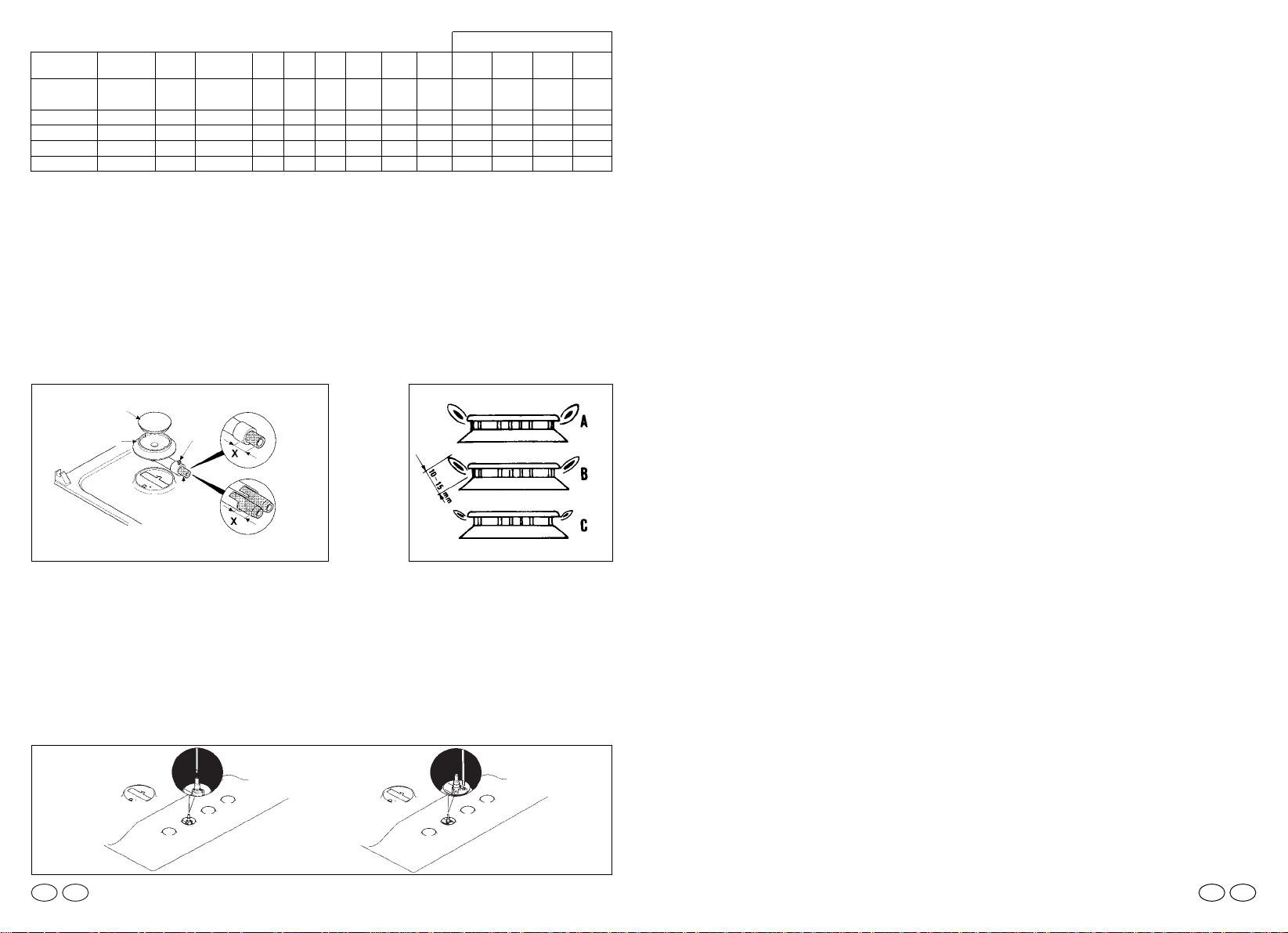
REGULATING THE MINIMUM FLAME
After lighting the burners, turn the control knob to the minimum setting and then remo-
ve the knob (this can easily be removed by apply a gentle pressure).
Using a small «Terminal» type screwdriver the regulating screw can be adjusted as in
Fig. 9. Turning the screw clockwise reduces the gas flow, whilst turning it anticlockwise
increases the flow – Use this adjustment to obtain a flame of approximately 3 to 4 mm
in length and then replace the control knob.
When the gas supply available is LPG (Bottle gas)- the screw to set the idle flame must
be turned (clockwise) to the end stop.
Screws regulating
(for differend models)
37
Fig. 9
Fig. 7 Fig. 8
BURNER
BURNER CAP
AIR REGULATION
SCREW
FIXING
SCREW
SMALL
MEDIUM
LARGE
DOUBLE RING
MAXI
FISH
For dimensions «X» see table of gas consumption
SETTING OF THE GAS BURNERS
When the jets have been changed it is necessary to set the correct air gap by keeping
to the setting “X” as shown in the table “ gas consumption” fig 7. Warning the value of ‘
X ‘ setting varies in relation to the size of gas burner and type of gas chosen.
A good flame must be of medium length (fig.8B), excessive air will cause the flame to
be short and with sharp colour (fig.8C): in this case it is necessary to extend out the tu-
be for the air setting from the burner body, if there is insufficient air the flame will ap-
pear weak and long (fig. 8A): in this case push the tube of the air setting back into the
burner body. To adjust the air setting tube loosen the retaining screw.
Once the air is correctly set secure the screw over the tube ( fig. 7).
air
regul.
4mm
2mm
13 mm
15 mm
Working
burner
large
medium
double ring
maxi
Ø injector
1/100 mm
120
93
2x94
2x94
Ø injector
1/100 mm
80
61
2x65
2x65
Qn
kW
2,65
1,5
3,3
3,3
l/h
G20
252
143
314
314
g/h
G30
193
109
238
238
g/h
G31
189
107
236
236
Qn
kW
2,5
1,45
3,1
3,1
l/h
G25
277
161
343
343
Qmin.
kW
0,650
0,380
0,900
0,900
air
regul.
4mm
2mm
13 mm
15 mm
air
regul.
2mm
5mm
0 mm
0 mm
G20 G30 G25 G31
G30
G31
G20/G25
G20 20mbar
G30 29mbar
G31 37mbar
G25
Quota «X» depending on type of gas
Table of gas consumption 1W = 0,860 kcal/h
air
regul.
5mm
7mm
15 mm
15 mm
GBIE
38
When you have carried out the new gas regulation, replace the old gas rating pla-
te on your appliance with one (supplied with hob) suitable for the type of gas for
which it has been regulated.
USE OF HOB
USER INSTRUCTIONS
This appliance must only be used for the purpose for which it is intended, domestic
cooking, and any other use will be considered improper and could therefore be danger-
ous. The Manufacturer will not be responisble for any damage or loss resulting from
improper use.
USING THE GAS BURNER
To ignite the burners, place a lighted taper close to the burner, press in and turn the
control knob anti-clockwise.
If the burners have not been used for a couple of days, wait for a few seconds before
lighting the burner, this will allow any air present in the pipes to escape.
For appliances fitted with electronic ignition carry out the following:
• push in and turn the knob anticlockwise to the
★
symbol.
• ignite the burner by pressing the sparker button.
For hobs fitted with automatic ignition simply push in and turn the knob to the
★
sym-
bol.
The ignition system will continue to generate sparks as long as the gas tap is being
pressed.
If the burner is not ignited within 5 seconds, turn the knob to the 0 position and repeat
the operation.
For models fitted with a safety tap (which cuts-off the flow of gas if the flame is acci-
dentally extinguished) the burners are ignited ad described above, but care must be
taken to keep the knob pressed in for 5 or 6 seconds after the flame is ignited.
ATTENTION:
Prior to switching on the gas hob ensure that the burners and bur-
ner caps are correctly placed within their position.
GENERAL ADVICE
For the best results, the flat-bottomed pans size should match the gas burner size as
follows. See fig. 1 pag. 31.
— Front right burner from 6 to 12 cm.
— Front left burner from 6 to 12 cm.
— Back right burner from 18 to 24 cm.
— Back left burner from 24 to 26 cm.
For smaller containers the gas burner should be regulated so that the flame does not
overlap the base of the pan. Vessels with concave or convex base should not be used.
WARNING: If a burner is accidentally extinguehed, turn the knob to the off posi-
tion and do not attempt to re-ignite if for at least 1 minute.
To protect the glass lid from damage and in the interests of safety, the burners/plates
must be turned off and the burner/pan support/plate area must be cool before closing
the lid down.
GB IE
Loading ...
Loading ...