
Loading ...
Loading ...
Loading ...
12
Preparation and Setup
WARNING
Make sure electrical service to the RNIVS is installed by a licensed electrician.
It is the owner’s responsibility to confirm that all electrical
requirements are met by a qualified electrician who is
servicing this appliance.
The electrical installation, including the minimum supply-
wire size and grounding, must be in accordance with the
National Electric code ANSI/NFPA* (or latest revision), local
codes, and ordinances.
*A copy of this standard can be obtained from:
National Fire Protection Association
1 Batterymarch Park
Quincy, Massachusetts 02269-9101
• The ground terminal inside the RNIVS must be con-
nected to a grounded, metallic, permanent wiring sys-
tem, or to a grounding conductor installed by a licensed
electrician.
• Do not ground the appliance or appliance wiring to a
gas pipeline or to the neutral (white) power supply wire.
• Do not install a fuse in the neutral or ground circuit.
• Connect the RNIVS directly to an electrical junc-
tion box. Hard-wire the RNIVS according to local code
directly to a dedicated three-wire grounded, single
phase circuit: rated at 120 Vac 60 Hz, 15 Amp.
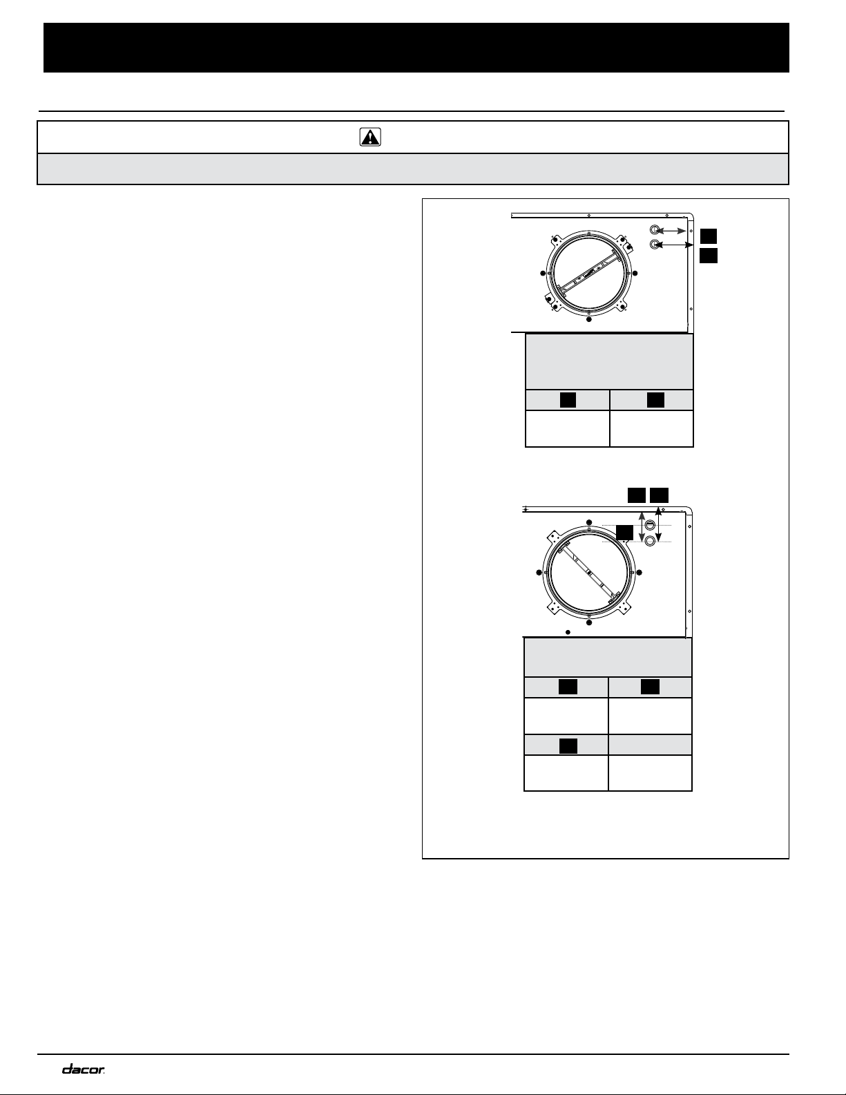
• See the diagram: Electrical Access Holes for wire
hole locations inside the RNIVS.
• See Wiring Diagrams at the end of this document.
Meeting Electrical Codes
Electrical access hole dimensions are the same on all
RNIVS models.
All tolerances are +1/16”, -0” (+0.16, -0 cm)
HORIZONTAL
DIMENSIONS
RNIVS1 & RNIVS2
A B
3
3
/8”
(8.57 cm)
3
15
/16”
(10.07 cm)
A
B
A B
Electrical Access Holes
VERTICAL DIMENSIONS
RNIVS1 & RNIVS2
C D
2
3
/4”
(7 cm)
3
3
/16”
(8.16 cm)
E Diameter
1
1
/2”
(3.81 cm)
7
/8”
(5.1 cm)
C
L
C D
E
C D
E
Loading ...
Loading ...
Loading ...