5W SOLAR
BATTERY CHARGER
MAINTAINER
User Guide
Model: RSP5BM
TABLE OF CONTENTS
IMPORTANT SAFETY INSTRUCTIONS 03
SPECIFICATIONS
04
PACKAGE CONTENTS
04
INSTALLATION
05
INTELLIGENT CHARGING TECHNOLOGY
08
WARRANTY
09
- 01 - - 02 -
IMPORTANT SAFETY INSTRUCTIONS
PACKAGE CONTENTS
SPECIFICATIONS
Please read the User Guide carefully before installation.
IMPORTANT SYMBOLS
Indicates potentially dangerous conditions that could result in personal
injury
Indicates conditions or practices that could result in damages to the
unit or other equipment
Indicates procedures or functions that are important for proper and
safe operation of the unit and/or other equipment
CAUTION
DO NOT operate the unit if it has been smashed, squashed, pierced, or
otherwise damaged in anyway.
The unit is designed to withstand splashes and spills but is not fully
waterproof. DO NOT submerge the unit in water or leave it in the rain.
CAUTION
Dispose of the unit according to the local recycling and environmental
regulations.
CAUTION
DO NOT step, walk, stand, or jump on the unit. Localized heavy loads may
cause variances of micro-cracks on the solar cells, which will ultimately
compromise the reliability of the unit.
CAUTION
Clean the surface of the solar battery charger maintainer as necessary for
optimal performance.
WARNING
DO NOT disassemble the unit or remove any attached components.
Incorrect reassembly may result in a risk of fire or electric shock.
WARNING
Keep the unit out of reach of children unless supervised by an adult.
WARNING
WARNING
The unit is only compatible with 12V lead-acid batteries. DO NOT connect it
to other types of batteries or batteries with nominal voltages other than 12V.
Doing so may cause irreversible damages to the unit and/or battery explosion.
WARNING
To reduce the risk of a battery explosion, please follow the instructions
published by the battery manufacturer and review the cautionary markings
on the battery carefully.
WARNING
DO NOT place the unit on a surface constructed from combustible material.
Keep the unit away from explosives and corrosive substances.
WARNING
NOTE
NOTE
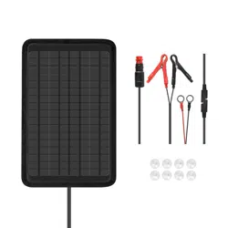
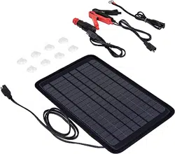
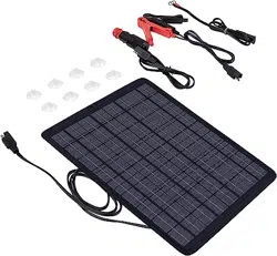
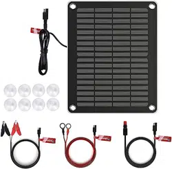
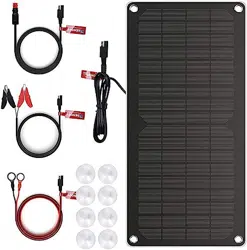
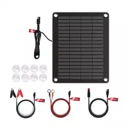
1 x Renogy 5W Solar Battery Charger Maintainer
1 x SAE to Ring Terminal Cable
1 x SAE to Alligator Clip Cable
1 x SAE to Cigarette Lighter Plug Cable
8 x Suction Cups
1 x User Guide
- 03 - - 04 -
Rated Maximum Power
Open Circuit Voltage
Short Circuit Current
Optimum Operating Voltage
Optimum Operating Current
Operating Temperature Range
Output Connector
Dimension
Weight
5W
21.6V
0.3A
18V
0.27A
-4~140 / -20~60
SAE
7.9 x 9.8 x 0.1 inch / 200 x 250 x 3 mm
10.5 oz / 298 g
Solar Panel
MPPT Charge Controller
Boost Voltage
Float Voltage
Maximum Input Current
Maximum Output Current
Operating Temperature Range
14.8V
13.55V
0.35A
0.4A
-4~185
/ -20~85
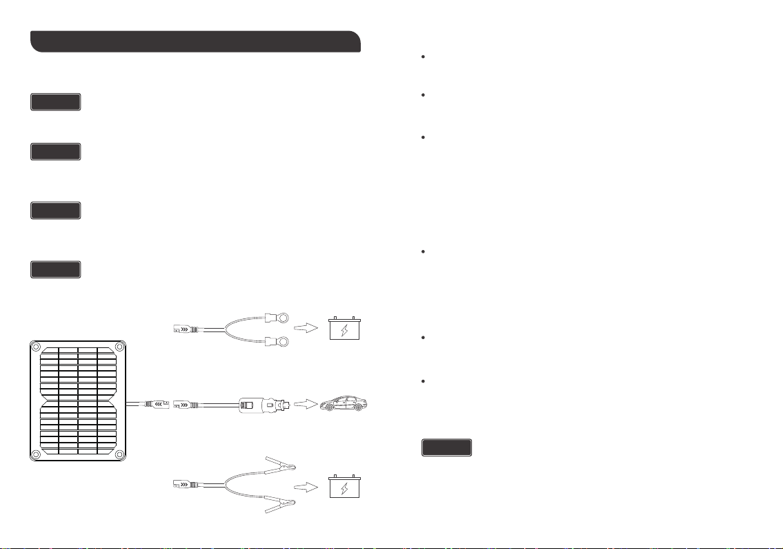
INSTALLATION
CONNECTING DIRECTLY TO THE BATTERY
The solar battery charger maintainer MUST be disconnected from the
battery or cigarette lighter port when starting the engine or driving the
vehicle. Electric surges from the alternator when starting and running may
damage the solar battery charger maintainer.
CAUTION
DO NOT leave the solar battery charger maintainer connected and
unattended for extended periods of time. Check the battery status frequent-
ly for safe operation.
WARNING
Place the solar battery charger maintainer as far away from the battery as
the adapter cables permit. DO NOT place it directly above the battery.
WARNING
The solar battery charger maintainer is designed to compensate for the
battery self-discharge. Please do not rely on it for a full charge.
NOTE
Check the polarity of the battery terminals. The positive (POS, P, +) terminal usually has
a larger diameter than the negative (NEG, N, -) terminal.
- 05 - - 06 -
Connect the included SAE to Ring Terminal Cable or SAE to Alligator Clip Cable to the
battery.
Connect the SAE to Ring Terminal Cable or SAE to Alligator Clip Cable to the solar battery
charger maintainer.
Place the solar battery charger maintainer, facing due south (or north), in the path of the
sun. Make sure that no shadows are cast on the solar battery charger maintainer.
If the battery is installed in the vehicle, the vehicle ground type must be identified. For a
negative-grounded vehicle, first connect the positive (red) alligator clip or ring terminal to
the positive (POS, P, +) terminal of the battery, and then connect the negative (black)
alligator clip or ring terminal to the vehicle chassis or engine block away from the battery.
For a positive-ground vehicle, first connect the negative (black) alligator clip or ring
terminal to the negative (NEG, N, -) terminal of the battery, and then connect the positive
(red) clip to the vehicle chassis or engine block away from the battery.
If the battery is outside the vehicle, a 24 inch (610mm) 6 AWG (13 mm2) insulated battery
cable must be first connected to the negative (NEG, N, -) battery terminal. Then connect
the positive (red) alligator clip or ring terminal to the positive (POS, P, +) terminal of the
battery and connect the negative (black) alligator clip or ring terminal to the free end of the
battery cable away from the battery.
Electric shock can occur if the adapter cable is damaged. DO NOT use a
damaged adapter cable to maintain or charge the battery. Position the
adapter cable properly to reduce the risk of damage by the hood, door, or
hot engine parts.
WARNING
For some makes or models of vehicles, the cigarette lighter port may not
operate when the ignition is turned off. In such cases, please connect the
solar battery charger maintainer to the battery directly.
NOTE
Dark window tints may seriously affect the performance of the solar battery
charger maintainer if it is attached to the inner side of the windshield. For
optimal performance, please route the adapter cable through the open
window and place the solar battery charger maintainer outside the vehicle.
NOTE
- 07 - - 08 -
CONNECTING TO THE CIGARETTE LIGHTER PORT
Park the vehicle in direct sunlight with the front facing due south (or north).
Connect the solar battery charger maintainer to the included SAE to Cigarette Lighter
Plug Cable.
Insert the cigarette lighter plug into the cigarette lighter port.
Attach the solar battery charger maintainer to the windshield using included Suction Cups.
Stay clear of fan blades, belts, pulleys, and other parts that can cause injury.
WARNING
NEVER allow the alligator clips or ring terminals to touch each other.
WARNING
When disconnecting the solar battery charger maintainer, please follow the
above procedures in reverse order.
WARNING
DO NOT connect the alligator clips or ring terminals to the carburetor, fuel
lines, or sheet-metal body part.
WARNING
If it is necessary to close the hood during the maintaining or charging
process, ensure that the hood does not touch the metal part of the alligator
clips or ring terminals, or cut the insulation of the adapter cable.
WARNING
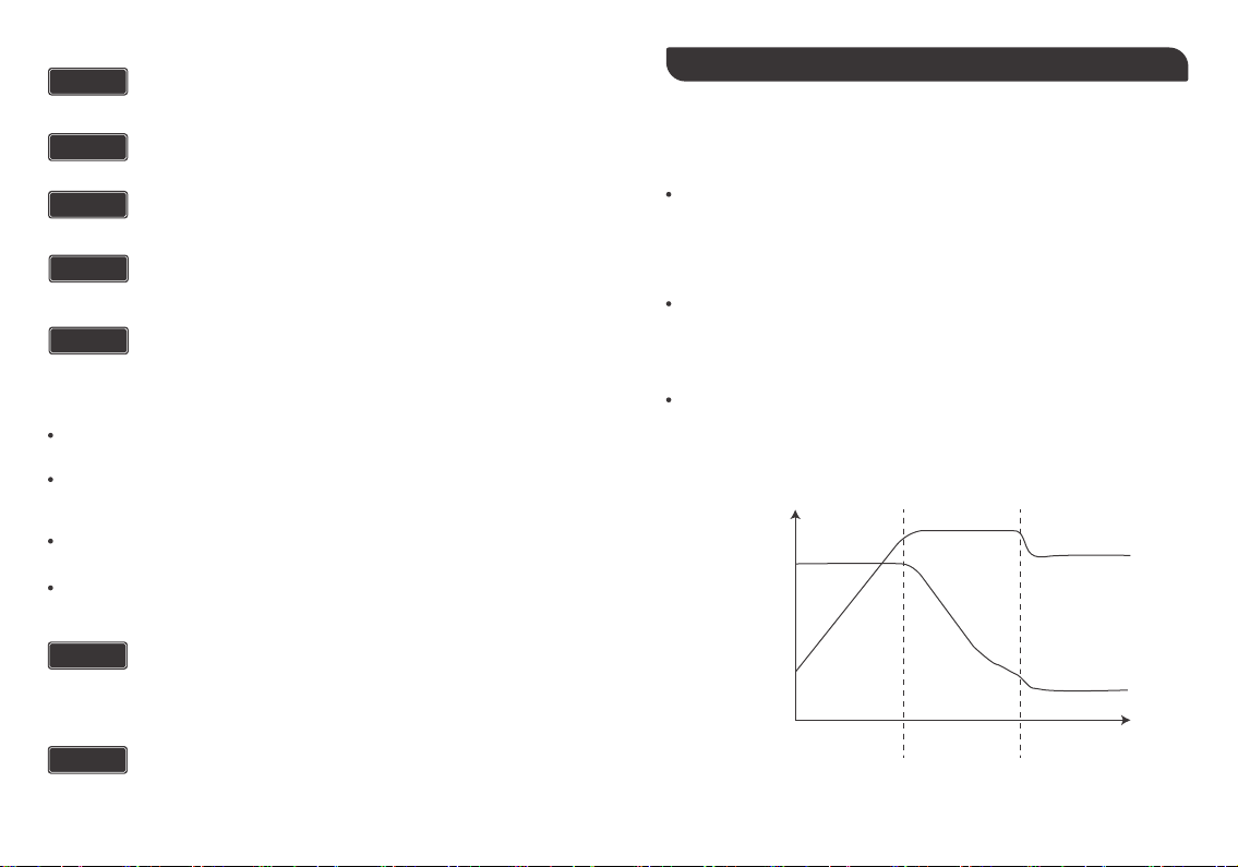
INTELLIGENT CHARGING TECHNOLOGY
Bulk Charge: During this stage, the built-in charge controller utilizes the MPPT
(Maximum Power Point Tracking) algorithm to automatically track the maximum power
point voltage of the solar panel and charges the battery at a constant maximum current
until the battery voltage increases to the boost voltage.
Boost Charge: During this stage, the built-in charge controller keeps the battery at the
boost voltage while gradually decreasing the charging current. The Boost Charge stage
helps the battery retain the energy stored during the Bulk Charge stage.
Float Charge: During this stage, the built-in charge controller charges the battery at the
float voltage with a small maintenance current, making up for the loss of battery
self-discharge. The Float Charge stage keeps the battery topped off once it is fully
charged.
The built-in charge controller employs a 3-stage charging algorithm for an efficient and safe
charging process, which includes bulk charge, boost charge, and float charge.
Battery Curent
Stage 1
Bulk Charge
Stage 2
Boost Charge
Stage 3
Float Charge
Battery Voltage

WARRANTY
RENOGY products are covered by a 1-year limited warranty from the original purchase
date. If any problems occur, please contact us for assistance. Refer to the last page of
User Guide for contact information.
We only provide after-sales services for products that are sold by RENOGY or retailers
and distributors authorized by RENOGY. If you have purchased your unit from other
channels, please contact your seller for more information about return and warranty.
Please register your purchase(s) directly at www.renogy.com/warranty-registration or
your region’s corresponding website so that we can stay in touch and contact you in the
unlikely event that a safety recall is required.
FCC Compliance:
This device complies with Part 15 of the FCC Rules. Operation is subject to the following
two conditions: (1) this device may not cause harmful interference, and (2) this device must
withstand any interference received, including interference that may cause undesired
operation.
- 09 -
Renogy reserves the right to change
the contents of this manual without notice.
RENOGY.COM
US
2775 E Philadelphia St, Ontario, CA 91761, USA
909-287-7111
www.renogy.com
support@renogy.com
https://www.renogy.cn
support@renogy.cn
CN
400-6636-695
苏州高新区科技城培源路1号5号楼-4
CA
https://ca.renogy.com
supportca@renogy.com
https://au.renogy.com
supportau@renogy.com
AU
JP
https://www.renogy.jp
supportjp@renogy.com
https://uk.renogy.com
supportuk@renogy.com
UK
https://de.renogy.com
supportde@renogy.com
DE