Loading ...
Loading ...
Loading ...
10
the insulation is removed from the cable
end. The acceptable diameter of the copper
stands size is 0.100 inches (2.54 mm) so it
will fit the into opening on the MI128 Con-
nection Plug.
B. If desired, the twisted ends can be tinned
with solder to keep the strands together.
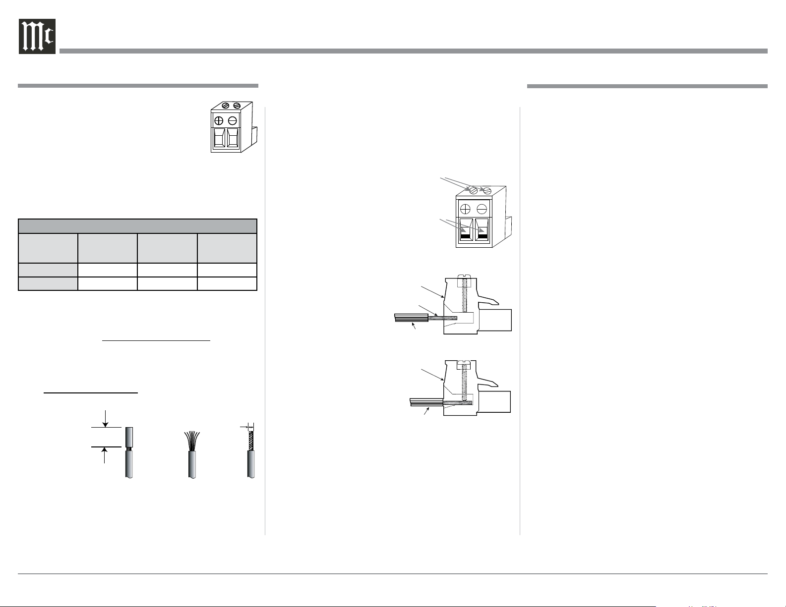
3. Adjust the two top screws of
the Loudspeaker Connection
Plug to provide a sufcient
opening size so the bare wire
will t into the connector.
Refer to gure 2.
4. Insert the Loudspeaker
Hookup Cable bare
wire end into the
Connection Plug
opening. Refer to
gure 3.
5. With the Hookup Ca-
ble insulation ush
with the Loudspeaker
Connection Plug
opening, now rotate
the two top screws to
secure the Hookup
Cable with the plug.
Refer to gure 4.
6. Now complete the remaining Loudspeaker Con-
nection Plugs and the Loudspeaker Hookup Cables
WARNING: The MI128 Chassis Loudspeaker Con-
nection Socket Pins present a risk of
electric shock when the Amplifier is
On. For additional assistance on using
Loudspeaker Connections Plugs con-
tact your McIntosh Dealer or McIntosh
Technical Support.
.
When connecting the Loudspeaker Hookup Cables to
the MI128 using the supplied Loudspeaker
Connection Plugs. Refer to figure 1.
1. When connecting Loudspeakers to the
MI128 it is very important to use cables
of adequate size, so there is little to no
power loss in the cables. The size is
specified in Gauge Numbers or AWG (American
Wire Gauge). The smaller the Gauge number, the
larger the wire size:
Loudspeaker Cable Distance vs Wire Gauge Guide
Loudspeaker
Impedance
25 feet
(7.62 meters)
or less
50 feet
(15.24 meters)
or less
100 feet
(30.48 meters)
or less
4 Ohms
14AWG 12AWG 10AWG
8 Ohms
16AWG 14AWG 12AWG
This McIntosh MI128 Power Amplifier is designed
for Loudspeakers with an impedance of 4 ohms or
8 ohms. Connect a single Loudspeaker only to each
Channel Output Terminal.
2. Prepare the Loudspeaker Hookup Cable for attach-
ment to the MI128 Power Amplifier:
Bare wire cable ends:
Carefully remove sufficient insulation from the
cable
ends,
refer to
figures
1, 2 &
3. If
the cable is stranded, carefully twist the strands
together as tightly as possible.
Notes: A. If the Loudspeaker Cable used is greater
in size than 12AWG, it can be used by
removing some of the copper strands after
How to Connect for Eight Zones
Caution: Do not connect the AC Power Cord to the MI128
Rear Panel until after the Loudspeaker Con-
nections are made. Failure to observe this could
result in Electric Shock.
The connection instructions below, together with the
MI128 Connection Diagram located on the separate
folded sheet “Mc1C”, is an example of a typical Mul-
tichannel System. Your system may vary from this,
however the actual components would be connected in
a similar manner. For additional information refer to
“Connector and Cable Information” on page 3.
1. For Power Remote Control of the MI128, connec-
tions from the Audio Source Components Power
Control Connection(s) can provide that operation.
Note: When the Power Control Cable is connected
between the MI128 and an Audio Source Com-
ponent, the AUTO OFF Sensing Circuitry of
the MI128 is disabled.
2. Connect a Power Control Cable from the Stream-
ing Audio Player Trigger (Power Control) Output
connector to the FM/AM Tuner Power Control IN
(Input) Connector.
3. Connect a second Power Control Cable from the
FM/AM Tuner Power Control OUT (Output) con-
nector to the MI128 POWER CONTROL INput
Connector.
4. Optionally, connect the MI128 POWER CON-
TROL OUTput if any of the Loudspeaker connect-
ed to the MI128 have Power Control In connectors.
5. Using a Digital Optical Cable connect the Stream-
ing Audio Player Audio Output Optical Connector
to the MI128 DIGital 1 Optical Input Connector.
6. Connect a Coaxial Digital Cable from the FM/AM
Tuner Digital Coaxial Output Connector to the
MI128 DIGital 2 Coaxial Input Connector.
Figure 2
Figure 3 Figure 4
0.100 inches
2.54 mm
0.5 inches
12.7 mm
Output Plug Connection
Figure 1
Cable Insulation
Loudspeaker
Connection
Plug
Figure 4
Cable Insulation
Cable Bare Wire
Loudspeaker
Connection
Plug
Figure 3
Figure 2
Openings
Screws
Loading ...
Loading ...
Loading ...