Loading ...
2
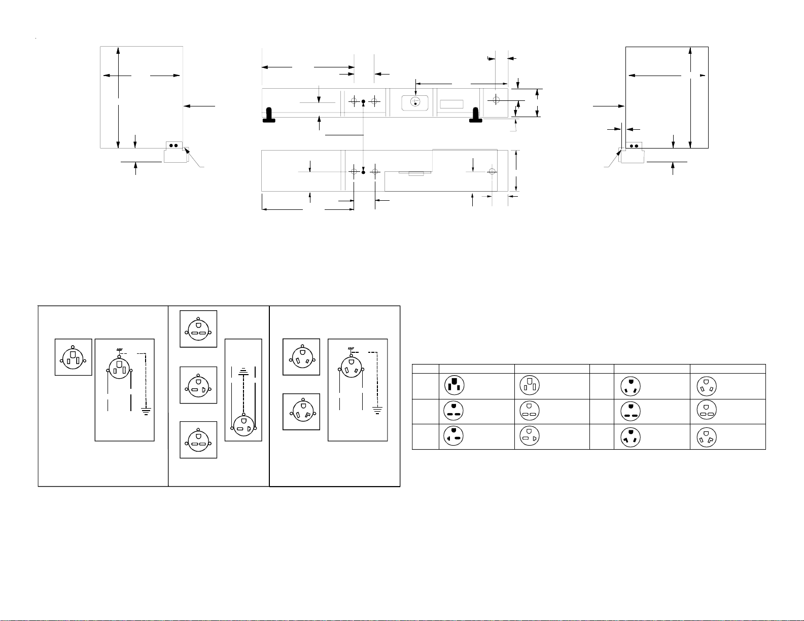
NEMA Plug Configurations
Voltage Unit Plug Subbase Receptacle
230/208
230/208
NEMA 6-15 AMP
NEMA 6-20 AMP
NEMA 6-15 AMP
NEMA 6-20 AMP
L2
L2
L1 L1
L1 L2
L2
L1
G
GG
NEMA 5 -15 AMP NEMA 5-15 AMP
L2 L1 L1 L2
115
230/208
265
265
NEMA 7-20 AMP
NEMA 6-30 AMP
NEMA 7-30 AMP
NEMA 7-20 AMP
NEMA 6-30 AMP
NEMA 7-30 AMP
L2
L2
L2
L1
L1
L1
L2
L2
L2
L1
L1
L1
G
G
G
W
W
G
W
G
W
Voltage Unit Plug Subbase Receptacle
Subbase Dimensions
1-1/4"
Wall Sleeve
(Outdoor Side)
16-1/16"
13-3/4"
3-1/4"
Left End View
Wall
Sleeve
Inside
Edge
Back of
Flange "A"
19-9/16"
1-3/8"
Ground
Screw Location
2"
19-9/16"
Concentric
Knockouts in Rear
Front View
Top View
Concentric
Knockouts in Bottom
3-1/2"
3-1/2"
Receptacle
Provided
Inside Subbase
Accessory
1-1/4"
1-3/8"
1-1/4"
2"
13-1/2"
2-5/8"
4"
2" Max. Adjustment
Wall Sleeve
(Inside Side)
16-1/16"
13-3/4"
3-1/4"
Right End View
Wall
Sleeve
Outdoor
Edge
Back of
Flange "A"
1-7/16"
NOTE: The subbase should
extend into the room 1-7/16"
past the wall sleeve flange.
NOTE: The subbase should
extend into the room 1-7/16"
past the wall sleeve flange.
Wiring Diagram
230/208 VAC Field Schematic 265 VAC Field Schematic
Field Wiring
Line Voltage
G
W
L1 L2
WHT
BLK
GRN
L2L1
G
W
NEMA 7-20R
Receptacle
NEMA 7-30R
Receptacle
L2L1
G
W
G
BLK RED
L1 L2
Field Wiring
Line Voltage
L2L1
L2L1
G
G
NEMA 6-20R
Receptacle
NEMA 6-30R
Receptacle
L2L1
G
NEMA 6-15R
Receptacle
115 VAC Field Schematic
L2L1
G
NEMA 5-15R
Receptacle
W
L1 L2
WHT
BLK
GRN
G
W
Field Wiring
Line Voltage