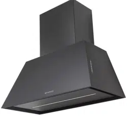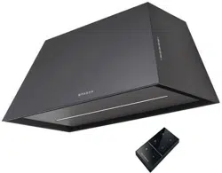
CHLO28BK600
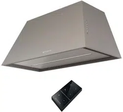
CHLO28GR600
Installation Instructions
Use and Care Information
Instructions d'installation
Utilisez et d'entretien
Instrucciones de instalación
Información de uso y cuidado
CHLOE'

2
READ AND SAVE THESE INSTRUCTIONS BEFORE YOU START
INSTALLING THIS RANGEHOOD
WARNING: - TO REDUCE THE RISK OF A RANGE TOP GREASE FIRE:
a) Never leave surface units unattended at high settings. Boilovers cause smoking and
greasy spillovers that may ignite. Heat oils slowly on low or medium setting.
A KV@XRSTQMGNNC.-VGDMBNNJHMF@SGHFGGD@SNQVGDMl@LADHMFENNCHD"QDODR
Suzette, Cherries Jubilee, Peppercorn Beef Flambé).
c) Clean ventilating fans frequently. Grease should not be allowed to accumulate on fan
NQkKSDQ
d) Use proper pan size. Always use cookware appropriate for the size of the surface element.
WARNING: - TO REDUCE THE RISK OF INJURY TO PERSONS IN THE EVENT OF A
RANGE TOP GREASE FIRE, OBSERVE THE FOLLOWING*:
@2,.3'$1%+ ,$2VHSG@BKNRDkSSHMFKHCBNNJHDRGDDSNQLDS@KSQ@XSGDMSTQMNEESGDATQMDQ
!$" 1$%4+3./1$5$-3!41-2(ESGDl@LDRCNMNSFNNTSHLLDCH@SDKX$5 "4 3$
AND CALL THE FIRE DEPARTMENT.
b) NEVER PICK UP A FLAMING PAN - You may be burned.
c) DO NOT USE WATER, including wet dishcloths or towels - a violent steam explosion will
result.
d) Use an extinguisher ONLY if:
1. You know you have a Class ABC extinguisher, and you already know how to operate it.
3GDkQDHRRL@KK@MCBNMS@HMDCHMSGD@QD@VGDQDHSRS@QSDC
3GDkQDCDO@QSLDMSHRADHMFB@KKDC
8NTB@MkFGSSGDkQDVHSGXNTQA@BJSN@MDWHS
* Based on "Kitchen Firesafety Tips" published by NFPA
WARNING - TO REDUCE THE RISK OF FIRE OR ELECTRIC SHOCK, do not use this
fan with any solid-state speed control device.
WARNING - TO REDUCE THE RISK OF FIRE, ELECTRICAL SHOCK, OR INJURY TO
PERSONS, OBSERVE THE FOLLOWING:
1. Use this unit only in the manner intended by the manufacturer. If you have any
questions, contact the manufacturer.
2. Before servicing or cleaning unit, switch power off at service panel and lock the
service disconnecting means to prevent power from being switched on acciden-
tally. When the service disconnecting means cannot be locked, securely fasten a
prominent warning device, such as a tag, to the service panel.
CAUTION: For General Ventilating Use Only. Do Not Use To Exhaust Hazardous or
Explosive Materials and Vapors.
WARNING - TO REDUCE THE RISK OF FIRE, ELECTRICAL SHOCK, OR INJURY TO
PERSONS, OBSERVE THE FOLLOWING:
1. (MRS@KK@SHNM6NQJ MC$KDBSQHB@K6HQHMF,TRS!D#NMD!X0T@KHkDC/DQRNMR(M BBNQ-
dance With All Applicable Codes And Standards, Including Fire-Rated Construction.
2. 2TEkBHDMS@HQHRMDDCDCENQOQNODQBNLATRSHNM@MCDWG@TRSHMFNEF@RDRSGQNTFG
SGDlTDBGHLMDXNEETDKATQMHMFDPTHOLDMSSNOQDUDMSA@BJCQ@ESHMF%NKKNVSGD
heating equipment manufacturer's guideline and safety standards such as those
OTAKHRGDC AXSGD-@SHNM@K%HQD/QNSDBSHNM RRNBH@SHNM-%/ @MCSGD LDQHB@M
2NBHDSXENQ'D@SHMF1DEQHFDQ@SHNM@MC HQ"NMCHSHNMHMF$MFHMDDQR 2'1 $@MC
the local code authorities.

3
ALL WALL AND FLOOR OPENINGS WHERE THE RANGEHOOD IS INSTALLED MUST
BE SEALED.
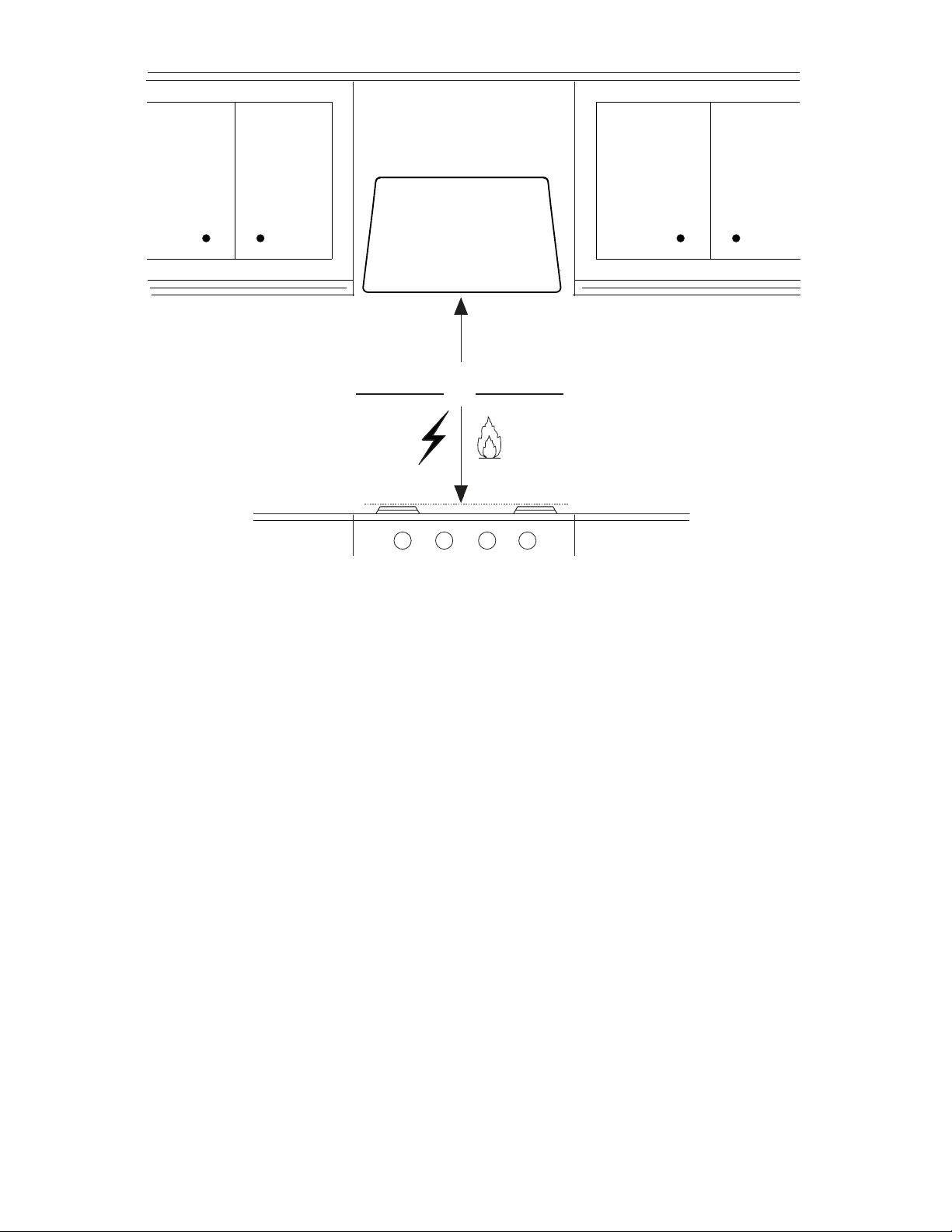
This rangehood requires at least 24" of clearance between the bottom of the rangehood
and the cooking surface or countertop. This hood has been approved by UL at this distance from
the cooktop.
This minimum clearance may be higher depending on local building codes. For gas cooktops and
combination ranges, a minimum of 30" is recommended and may be required.
The maximum depth of overhead cabinets is 13". Overhead cabinets on both sides of this unit
must be a minimum of 18" above the cooking surface or countertop. Consult the cooktop or range
installation instructions given by the manufacturer before making any cutouts.
MOBILE HOME INSTALLATION The installation of this rangehood must conform to the Manufactured
Home Construction and Safety Standards, Title 24 CFR, Part 3280 (formerly Federal Standard
for Mobile Home Construction and Safety, Title 24, HUD, Part 280). See Electrical Requirements.
• Venting system MUST terminate outside the home.
• DO NOT terminate the ductwork in an attic or other enclosed space.
• DO NOT use 4" laundry-type wall caps.
• Flexible-type ductwork is not recommended.
• DO NOTNARSQTBSSGDkNVNEBNLATRSHNM@MCUDMSHK@SHNM@HQ
q%@HKTQDSNENKKNVUDMSHMFQDPTHQDLDMSRL@XQDRTKSHM@jQD
WARNING
!
Cold Weather installations
M@CCHSHNM@KA@BJCQ@ESC@LODQRGNTKCADHMRS@KKDCSNLHMHLHYDA@BJV@QCBNKC@HQkNV@MC@
nonmetallic thermal break should be installed to minimize conduction of outside temperatures as
part of the vent system. The damper should be on the cold air side of the thermal break. The break
should be as close as possible to where the vent system enters the heated portion of the house.
VENTING REQUIREMENTS
Determine which venting method is best for your application. Ductwork can extend either through the
wall or the roof.
3GDKDMFSGNESGDCTBSVNQJ@MCSGDMTLADQNEDKANVRRGNTKCADJDOSSN@LHMHLTLSNOQNUHCDDEjBHDMS
performance. The size of the ductwork should be uniform. Do not install two elbows together. Use
CTBSS@ODSNRD@K@KKINHMSRHMSGDCTBSVNQJRXRSDL4RDB@TKJHMFSNRD@KDWSDQHNQV@KKNQkNNQNODMHMF
around the cap.
Flexible ductwork is not recommended. Flexible ductwork creates back pressure and air
turbulence that greatly reduces performance.
,@JDRTQDSGDQDHROQNODQBKD@Q@MBDVHSGHMSGDV@KKNQkNNQENQDWG@TRSCTBSADENQDL@JHMFBTSNTSR
Do not cut a joist or stud unless absolutely necessary. If a joist or stud must be cut, then a supporting
frame must be constructed.
WARNING - To Reduce The Risk Of Fire, Use Only Metal Ductwork.
" 43(.-3NQDCTBDQHRJNEkQD@MCSNOQNODQKXDWG@TRS@HQADRTQDSNCTBS@HQNTSRHCDm#N
not vent exhaust air into spaces within walls or ceilings or into attics, crawl spaces, or garages.
3. When cutting or drilling into wall or ceiling, do not damage electrical wiring and
other hidden utilities.
4. Ducted fans must always be vented to the outdoors.
4
ELECTRICAL REQUIREMENTS
A 120 volt, 60 Hz AC-only electrical supply is required on a separate 15 amp fused circuit. A time-delay
fuse or circuit breaker is recommended. The fuse must be sized per local codes in accordance with
SGDDKDBSQHB@KQ@SHMFNESGHRTMHS@RRODBHjDCNMSGDRDQH@KQ@SHMFOK@SDKNB@SDCHMRHCDSGDTMHSMD@QSGDjDKC
wiring compartment.
ELECTRICAL INSTALLATION WITH WIRING BOX
THIS UNIT MUST BE CONNECTED WITH COPPER WIRE ONLY. Wire sizes must conform to the
QDPTHQDLDMSRNESGD-@SHNM@K$KDBSQHB@K"NCD -2(-%/ K@SDRSDCHSHNM@MC@KKKNB@KBNCDR@MC
ordinances. Wire size and connections must conform with the rating of the appliance. Copies of the
standard listed above may be obtained from:
National Fire Protection Association
Batterymarch Park
Quincy, Massachusetts 02269
This appliance should be connected directly to the fused disconnect (or circuit breaker) through
kDWHAKD@QLNQDCNQMNMLDS@KKHBRGD@SGDCBNOODQB@AKD KKNVRNLDRK@BJHMSGDB@AKDRNSGD
@OOKH@MBDB@MADLNUDCHERDQUHBHMFHRDUDQMDBDRR@QX 4++HRSDCŭBNMCTHSBNMMDBSNQLTRS
be provided at each end of the power supply cable (at the appliance and at the junction box).
6GDML@JHMFSGDDKDBSQHB@KBNMMDBSHNMBTS@ŭGNKDHMSGDV@KK GNKDBTSSGQNTFGVNNC
must be sanded until smooth. A hole through metal must have a grommet.
• Electrical ground is required on this rangehood.
• If cold water pipe is interrupted by plastic, nonmetallic gaskets or other materials, DO
NOT use for grounding.
• DO NOT ground to a gas pipe.
• DO NOT have a fuse in the neutral or grounding circuit. A fuse in the neutral or
grounding circuit could result in electrical shock.
q"GDBJVHSG@PT@KHjDCDKDBSQHBH@MHEXNT@QDHMCNTAS@RSNVGDSGDQSGDQ@MFDGNNCHR
properly grounded.
q%@HKTQDSNENKKNVDKDBSQHB@KQDPTHQDLDMSRL@XQDRTKSHM@jQD
WARNING
5
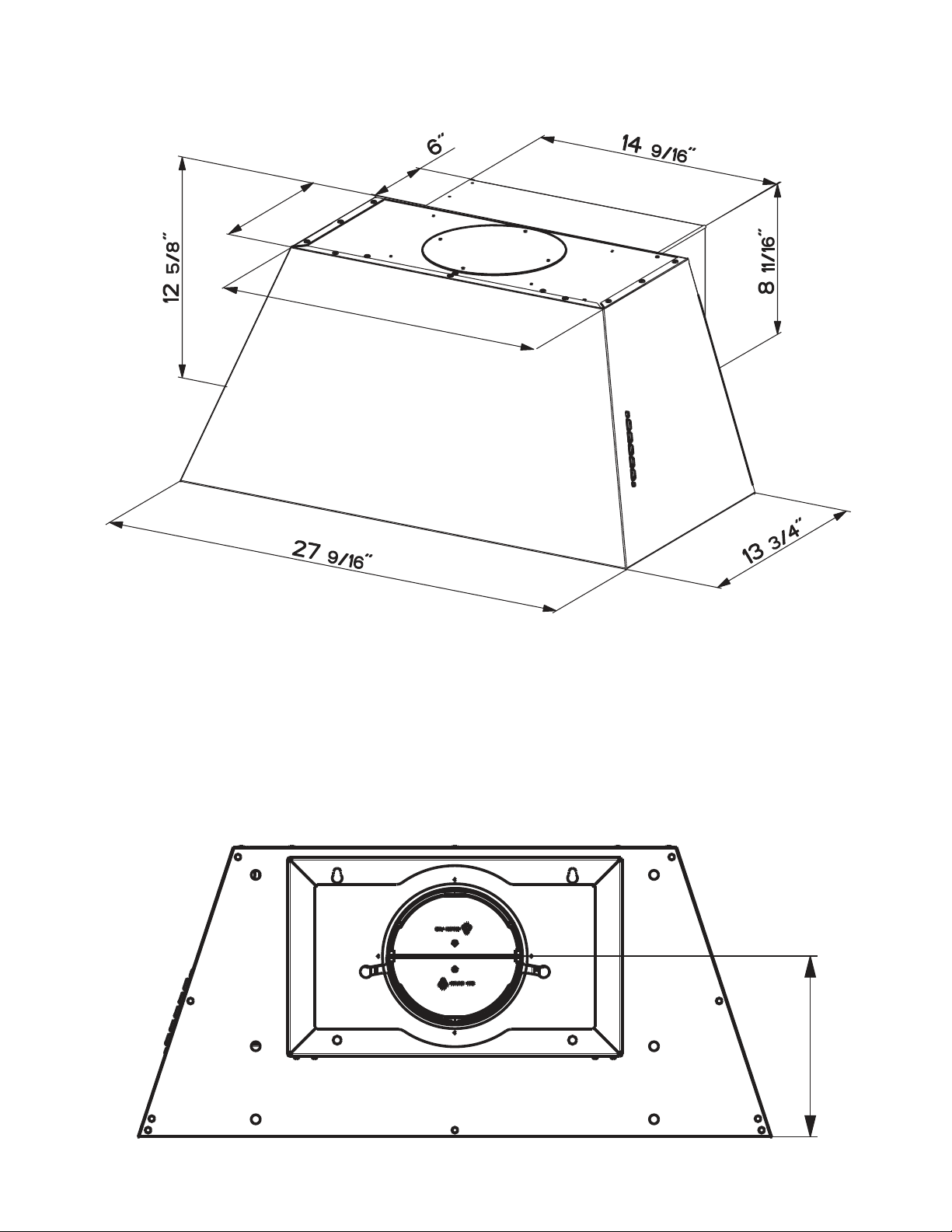
RANGEHOOD DIMENSIONS
´
´
7-11/16"
7 11/16"
REAR DUCTED VENTING INSTALLATION
SGD'NNCRGNTKCBNLDRDSHMSGHRONRHSHNM

6
Min. 24" Min. 30"

7
Available Accessories
Recirculation Vent Kit - Activated Charcoal Filter - sku # FILTER1
Washable Long Lasting Charcoal Filter Kit - sku#FILTER1LL
Telescopic Chimney Accessory Kit - Upper and Lower Chimney Flue for Ducted or Recirculation Venting -
sku# CHIMCHGR - Grey / sku#CHIMCHBK - Black
Wireless Remote Control Accessory - REMCTRL
Cfm reducer kit (600-400) - sk# CFMRED-2
Cfm reducer kit (600-300) - sku#CFMRED
Parts needed
- 6" Round Metal ductwork .
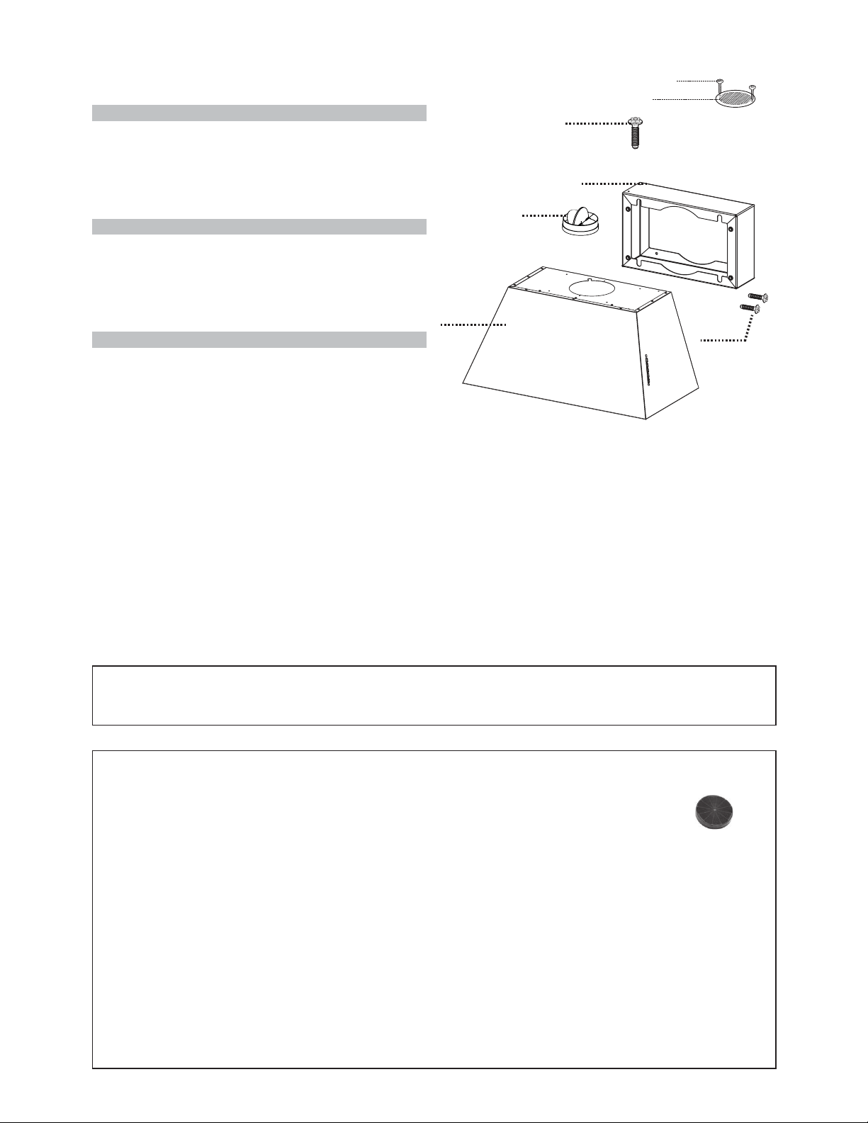
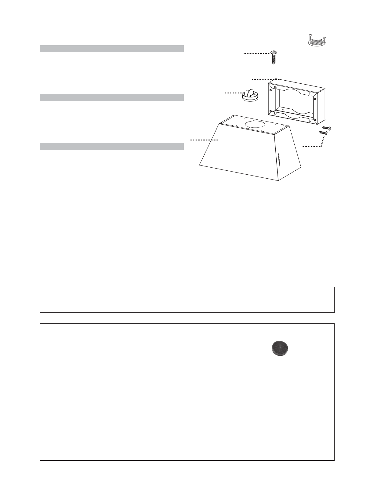
MAIN PARTS
Components
Ref. Qty. Product Components
1 1 Hood Body, complete with: Con-
trols, Light, Filters, Blower.
2 1 Rear Section
8 1 Recirculation Vent Grill
10 1 Damper ø 5 7/8"
Ref. Qty. Installation Components
12a 4 Screws 1/4" x 9/16"
12b 2 Screws 1/8"x3/8" (for Wiring Box
mounting)
12e 2 Screws 1/8"x3/8" (for Recirculation
Vent Grill mounting)
Qty. Documentation
1 Instruction Manual
10
1
12a
2
H
I
12b
8
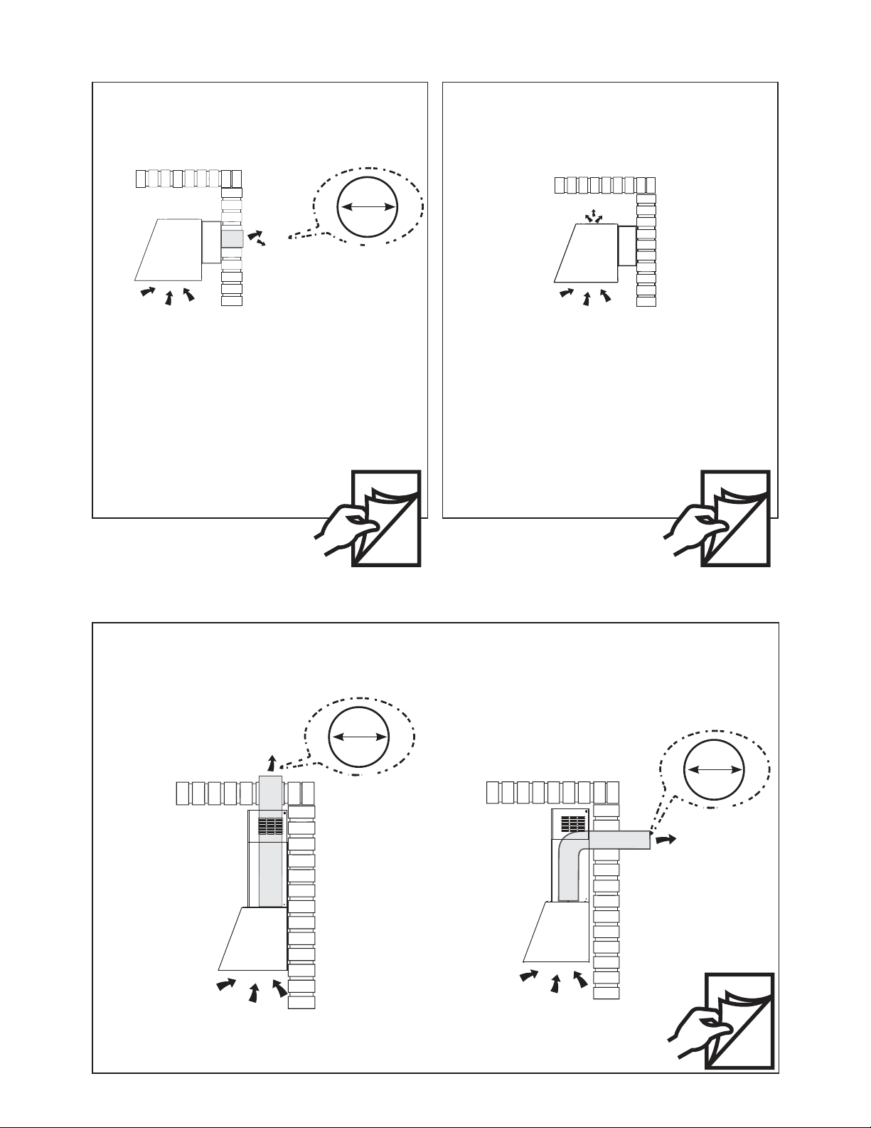
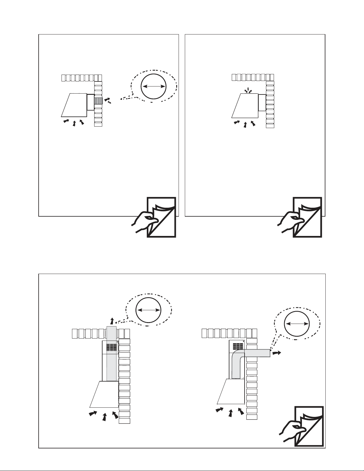
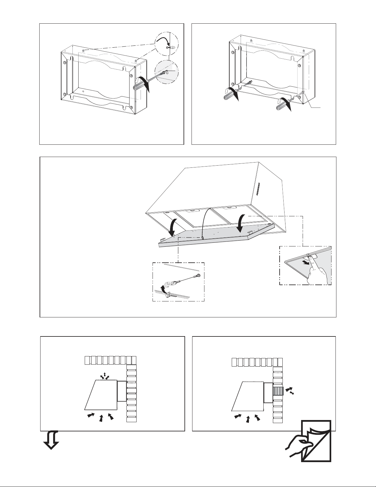
Choose your ducting method
Non Ducted - Recirculation OptionDucted Venting Options Installation
Requires purchase of Activated Charcoal Accessory
Horizontal
Vertical
6"
When used in recirculation mode, To Reduce the
Risk of Fire and Shock use only conversion kit
Model FILTER1
Rear
Requires purchase of Chimney accessory
18
Vertical and Horizontal Ducted Venting Installation with the optional Kit Chimney
6"
6"
9 9
9
1
2
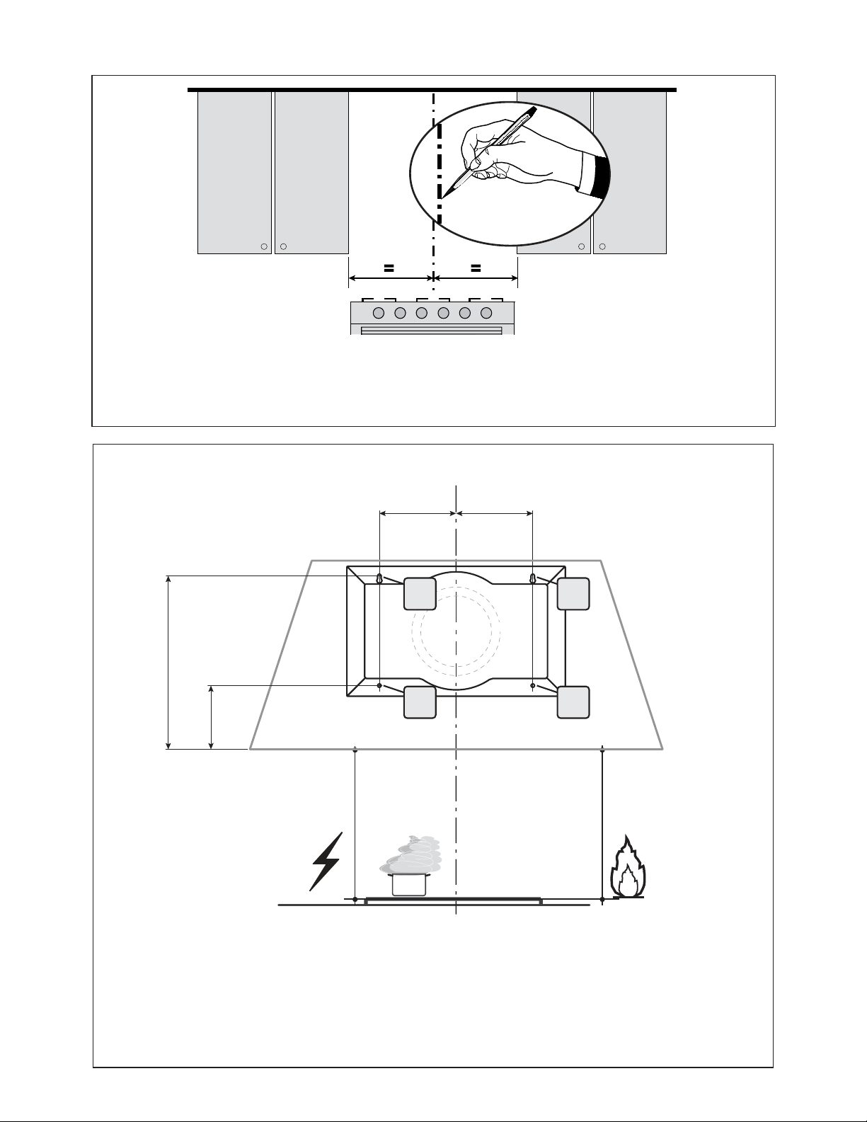
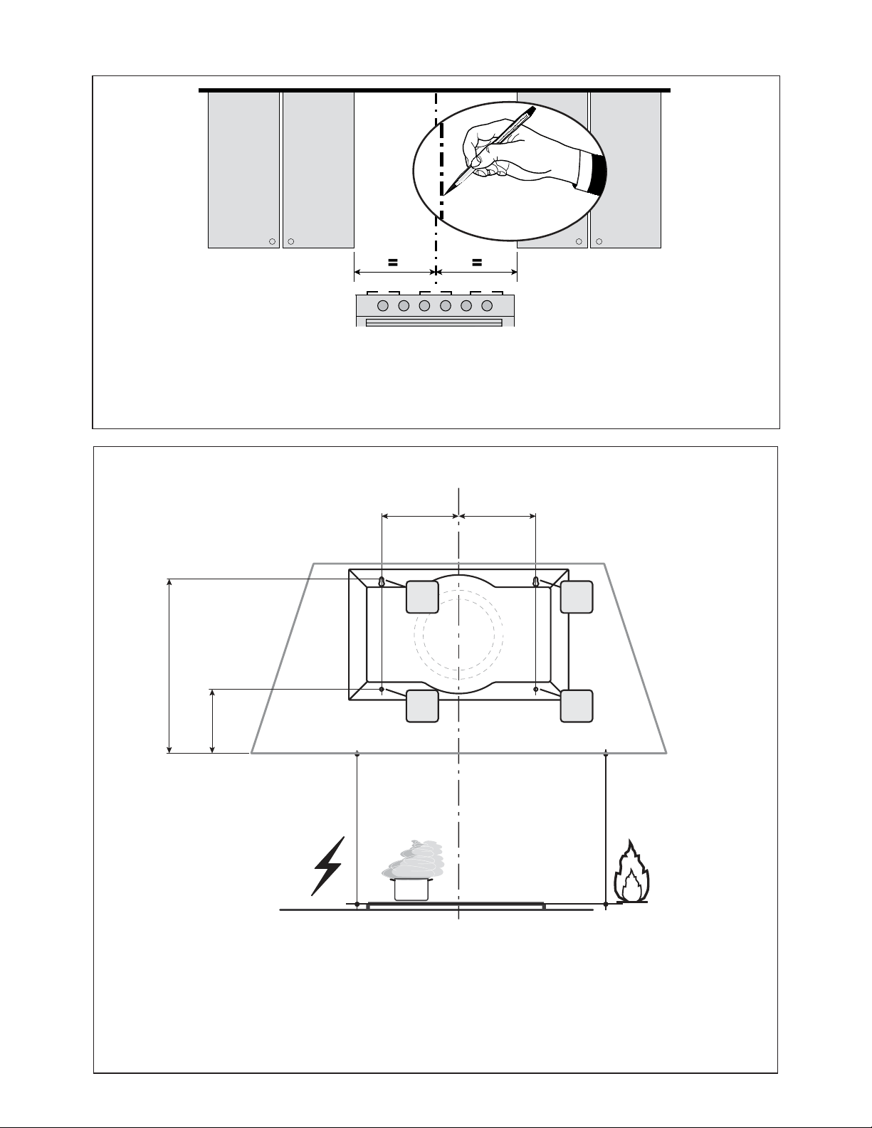
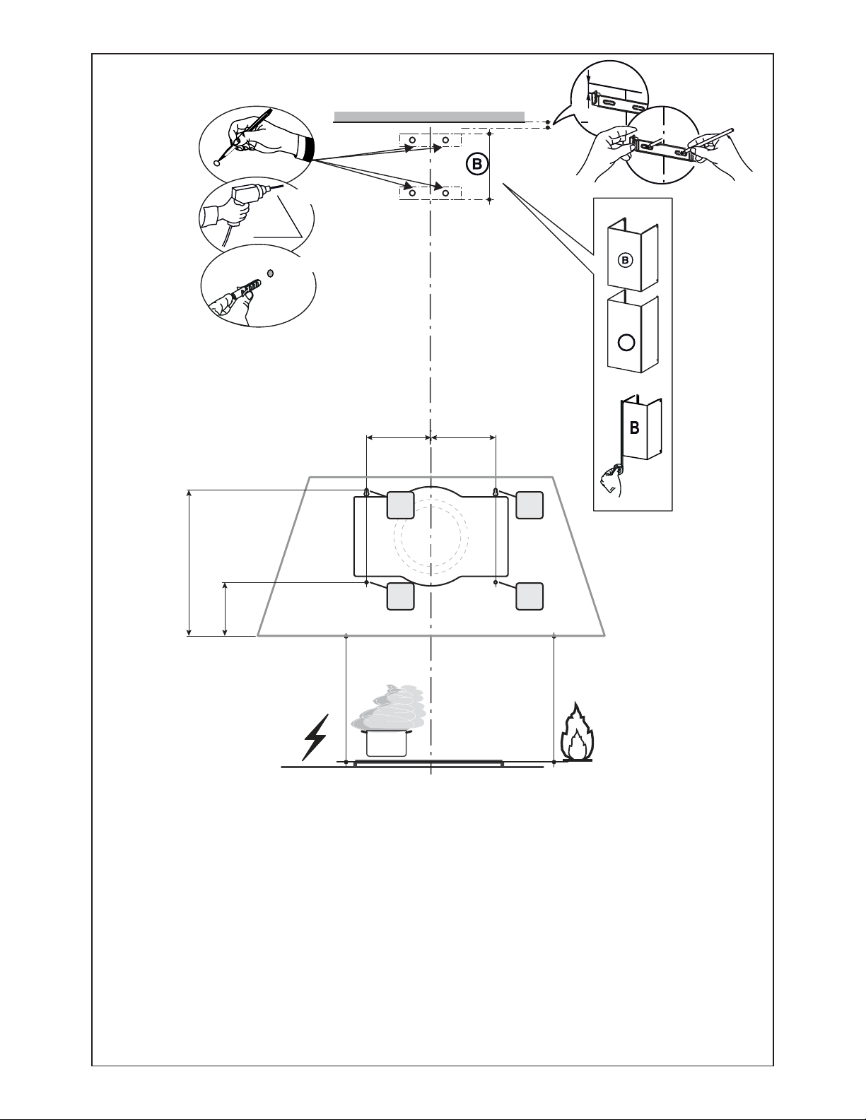
Draw a vertical line on the supporting wall as high as practical, at the center of the area in which the hood will be installed.
'UDZDKRUL]RQWDOOLQHDWZKHUHWKHERWWRPHGJHRIWKHKRRGZLOOEHORFDWHGDVLQGLFDWHGLQWKH¿JXUHWKDWLVDPLQLPXP
of 24" above Electric cooking surface and 30" above Gas.
Mark the wall where indicated (A), 11 9/16" above the horizontal line and at 4 5/16" distance on the left and right of vertical
line. Checking that the two marks are level.
Insert two wall plugs and screws (purchased separately) into the (A) holes as shown and leave 1/4" of screws exposed.
Mark the wall where indicated (B), 4 1/4" above the horizontal line and at 4 5/16" distance on the left and right of vertical
line. Checking that the two marks are level.
Insert two wall plugs (purchased separately).
Installation Instructions
Rear Section Installation
´
´
11
9/16”
4
1/4”
4
5/16” 4 5/16”
$
%
$
%
10
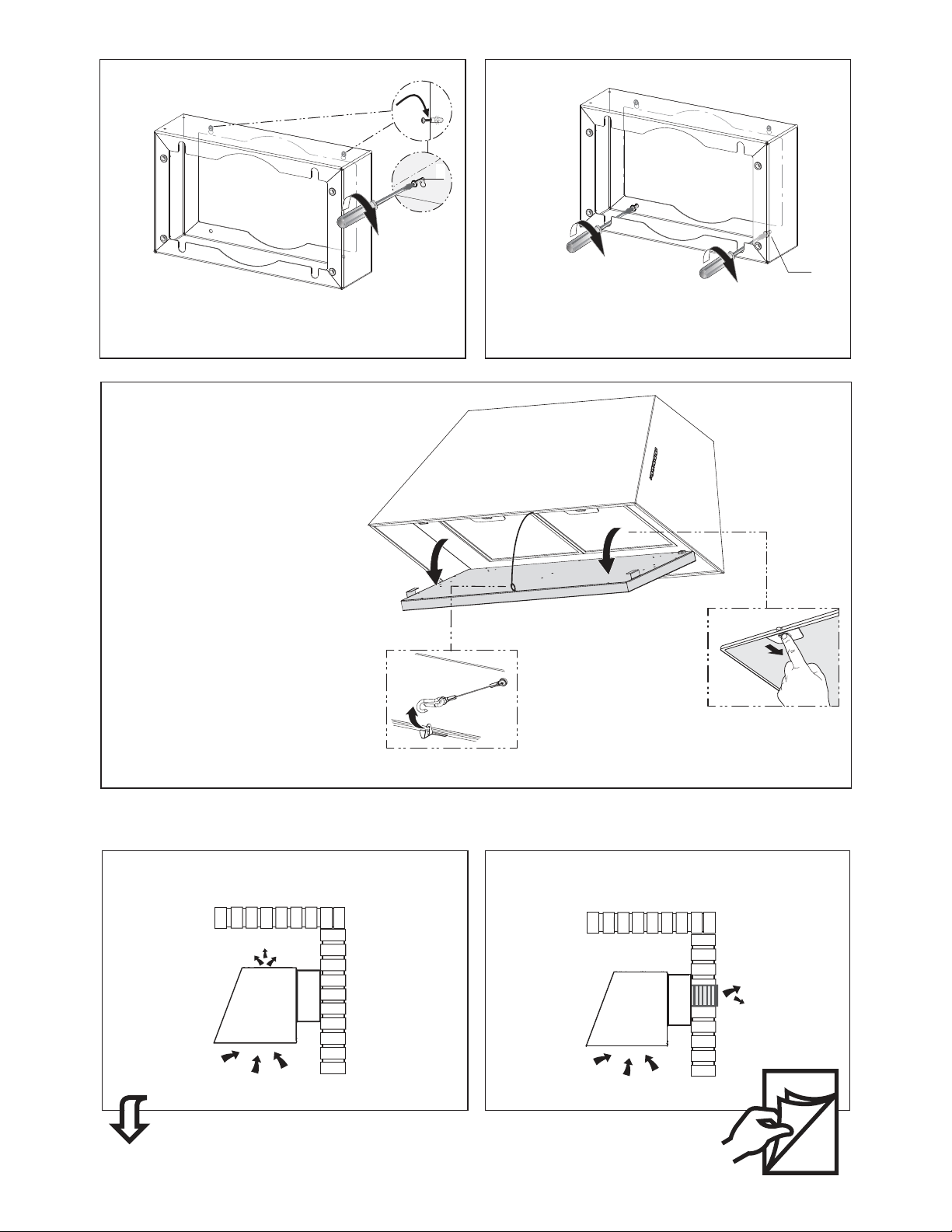
3
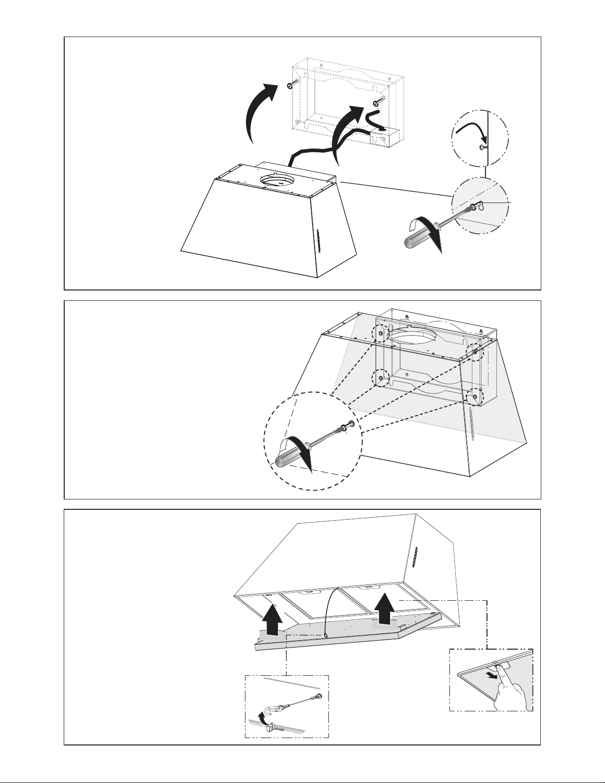
Hook the Rear Section as shown in the image above
onto the upper screws and fully secure.
From inside fully secure the two lower screws (purchased
separately).
4
L
2x
L
2x
5
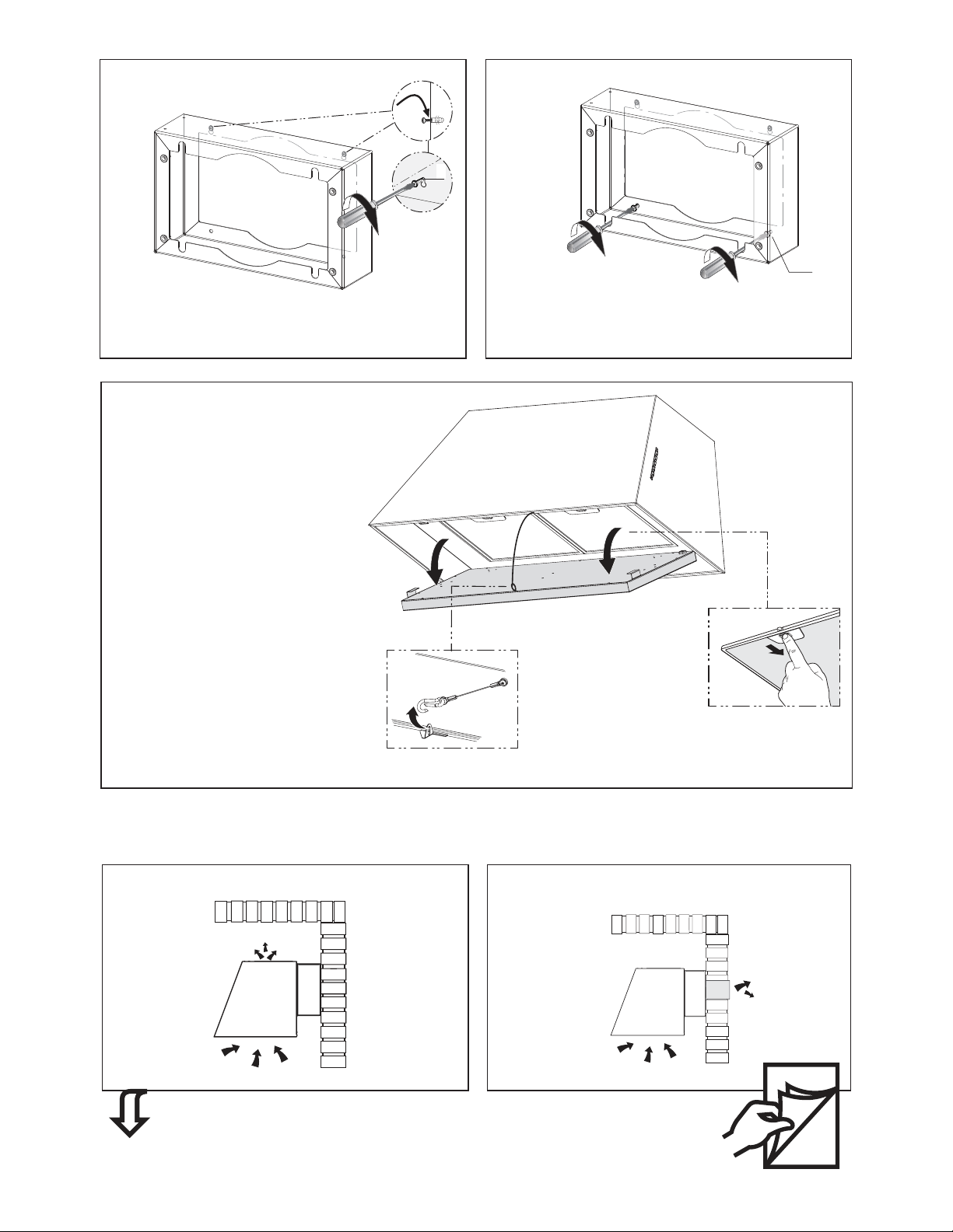
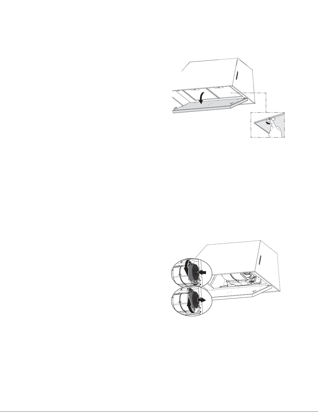
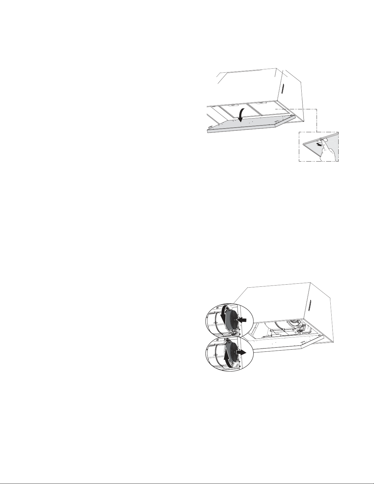
Open the panel, unlock the security cable as
VKRZQ5HPRYHWKH¿OWHUVE\SXVKLQJWKHOHYHU
towards the back of the unit and at the same
time pulling downward. Do not discard the
¿OWHUVDQGVHWDVLGHIRUIXWXUHXVH
For Non-Ducted Recirculation Option
13
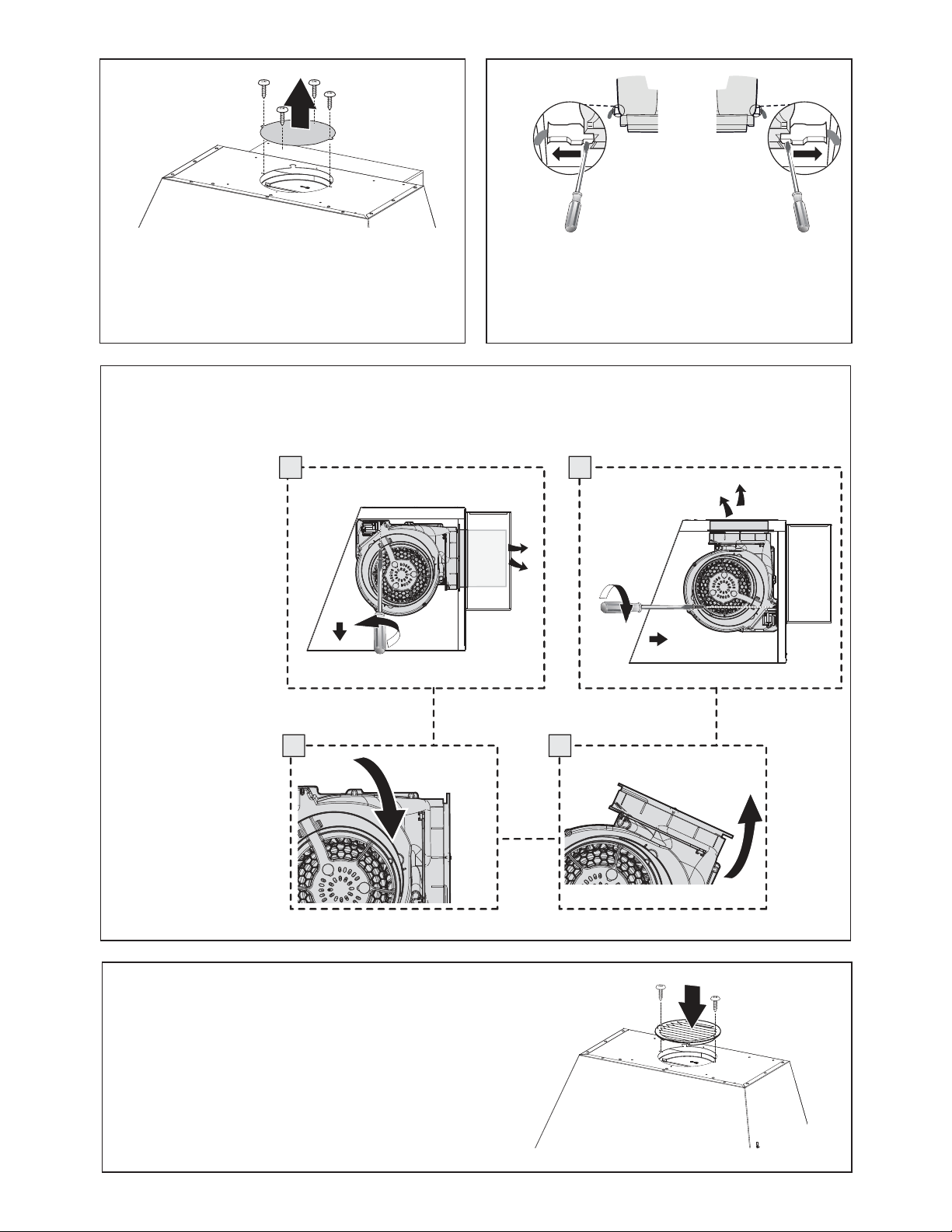
Rear Ducting Installation
11
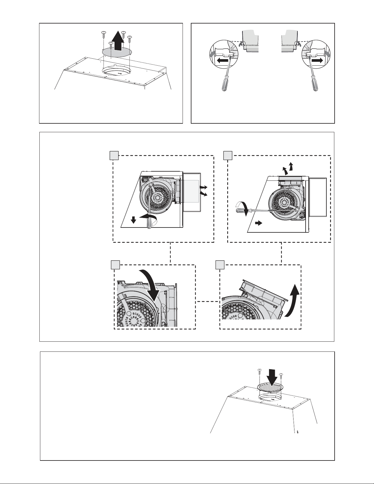
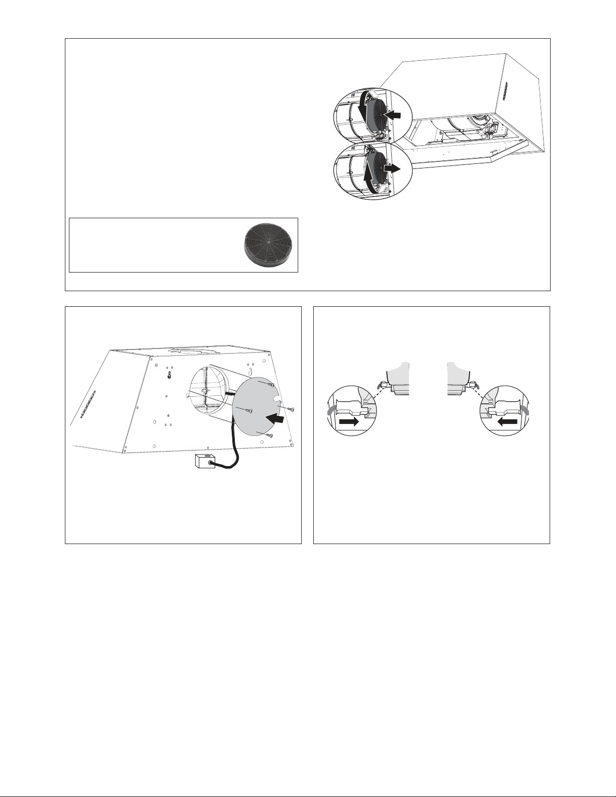
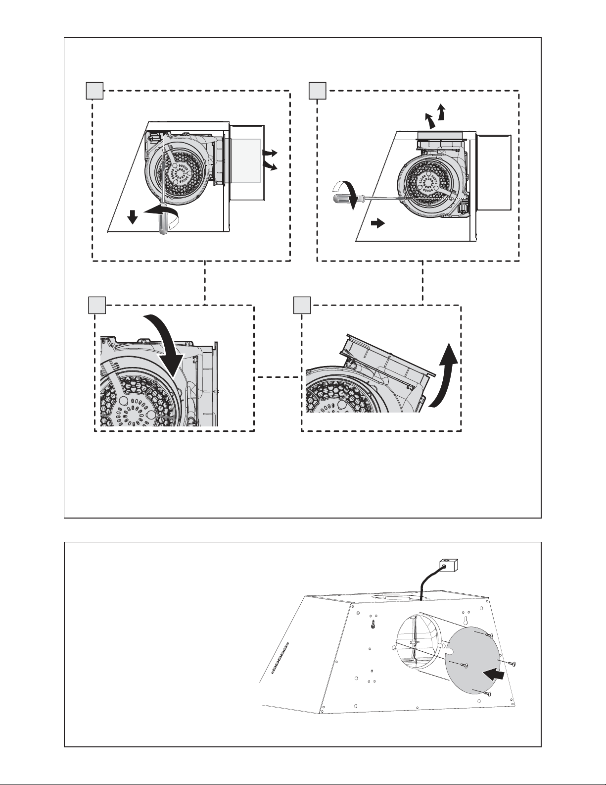
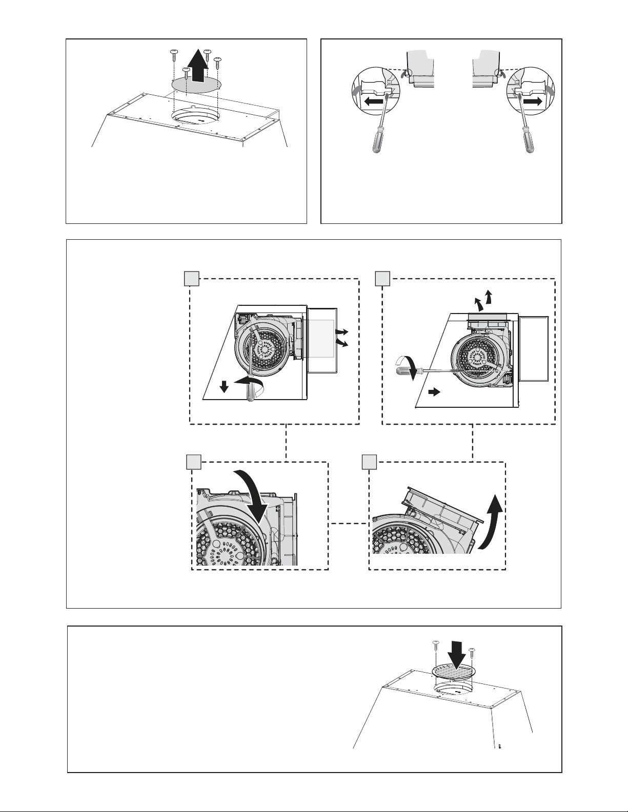
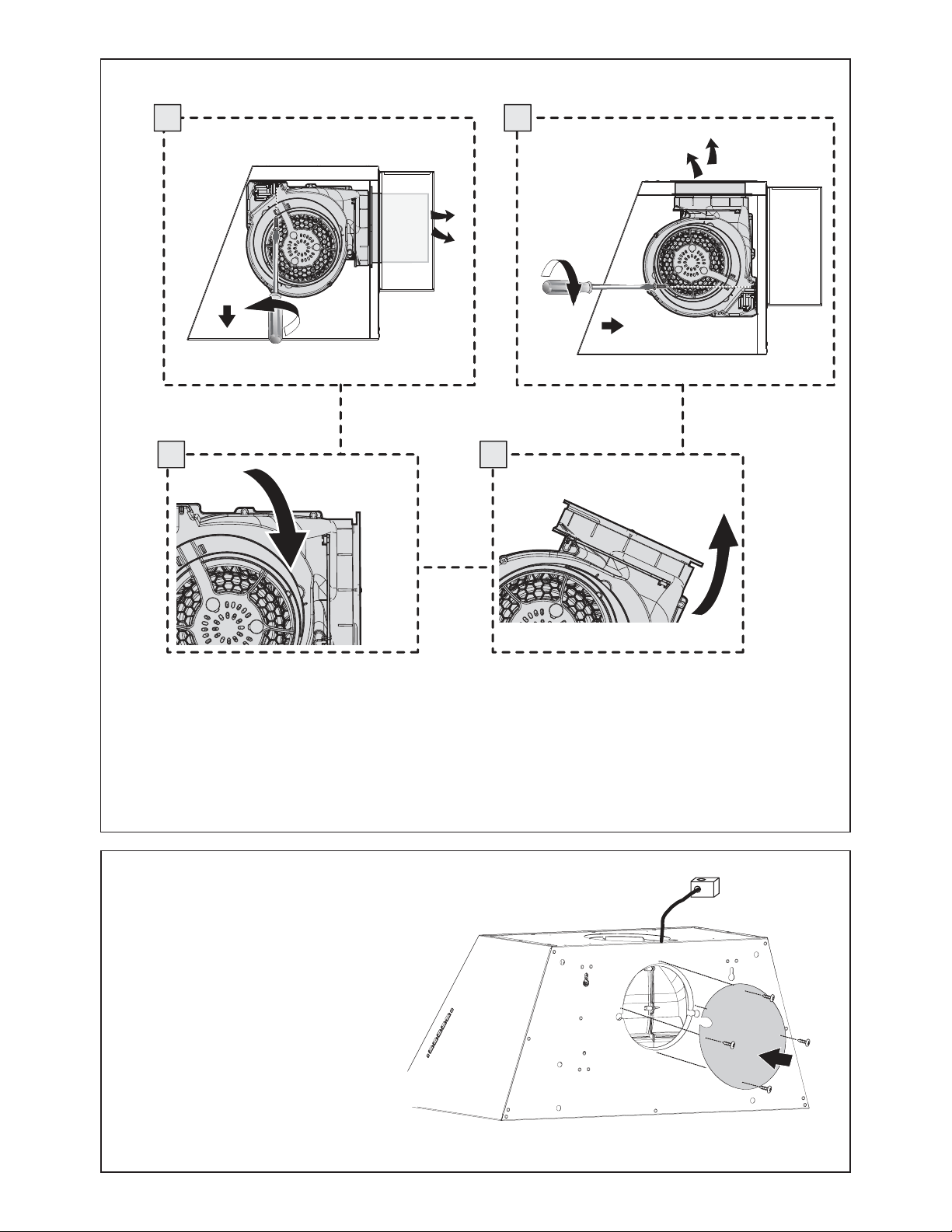
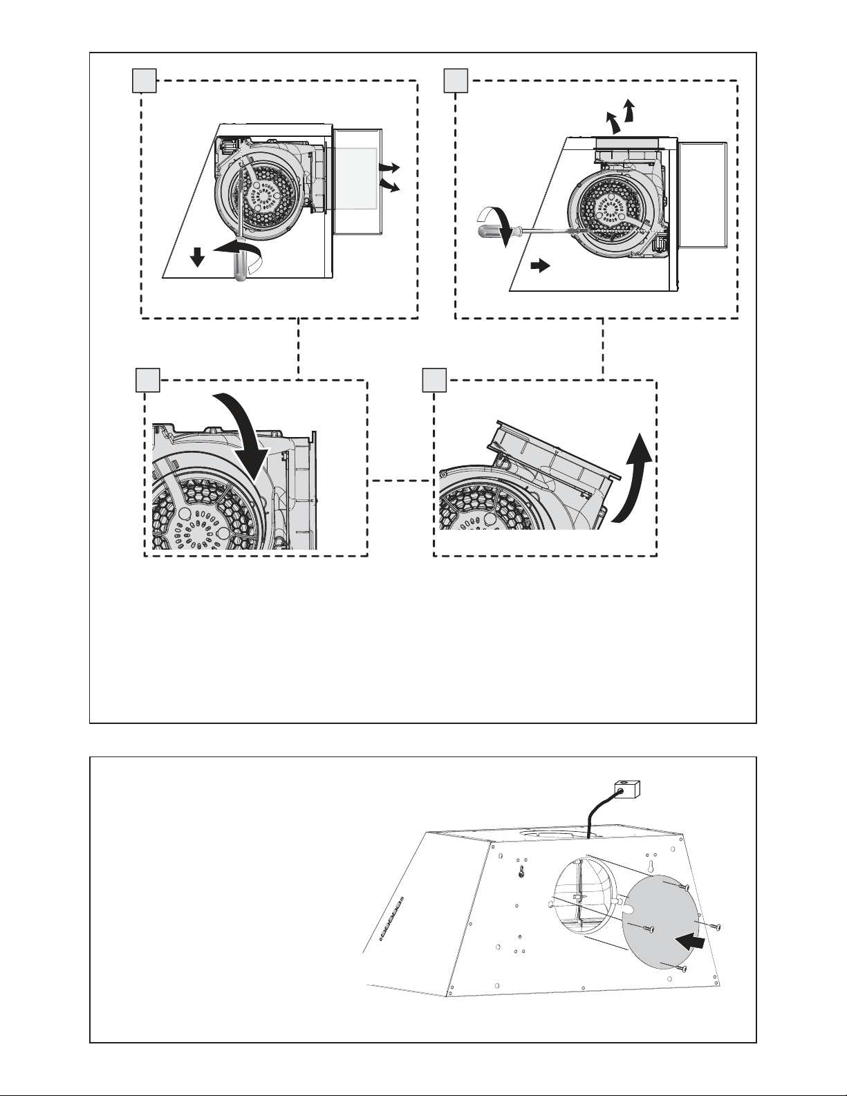
Remove the 4 screws as shown and take off the cover plates.
Do not discard and set aside for future use.
)URPLQVLGHWKHKRRGXVHDÀDWKHDGVFUHZGULYHUDVVKRZQLQ
image above, to disconnect the left and right Connectors from
the blower.
6
Unscrew the 2 screws
(Posi-Drive) that hold
the blower and unlock it
from the initial position as
shown in Image a.
E F
D G
[
[
After removing blower
rotate as shown until it is
in the correct rear venting
position as shown in
Image b-c.
Use the two screws that
were removed to secure
the blower as shown in
Image d.
7
8
P
P1
2x
Fix the Recirculation Vent Grill with two screws.
9
12e
12
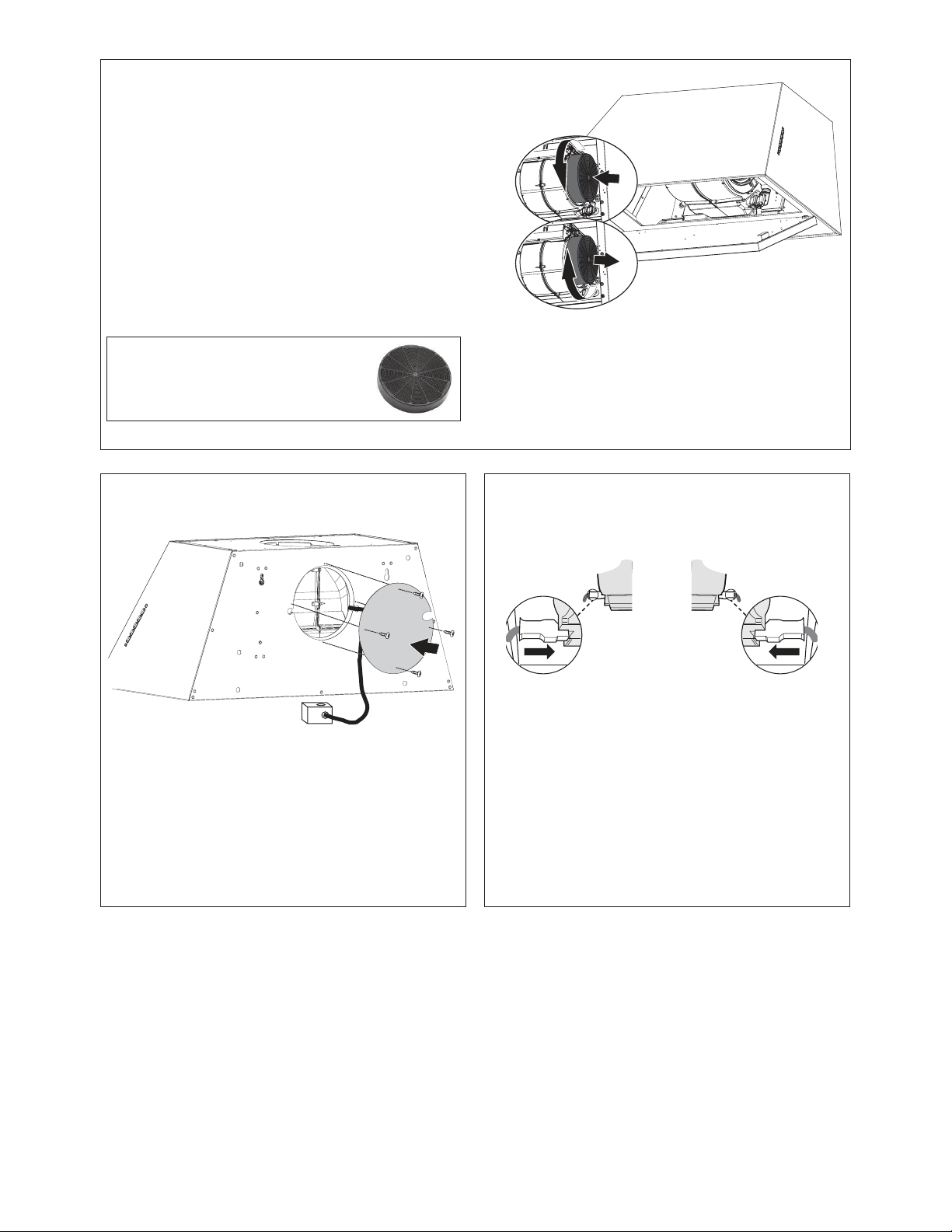
A10
Fix the cover plate with the 4 screws removed previously and
route the wiring box outside of the hood body through the notch
on the cover plate.
$WWDFKHDFKFKDUFRDO¿OWHUWRWKHEODFNJULGRQHDFKVLGHRIWKH
EORZHU3UHVVWKHFKDUFRDO¿OWHUWLJKWO\WRWKHEODFNJULGRQWKH
EORZHUVLGHDQGURWDWHWKH¿OWHUFORFNZLVHWRZDUGVWKHIURQW
of the hood) until it locks into place. Turn counterclockwise
(towards the back of the hood) to remove.
Required Activated Charcoal Filter Accessory -
sku # - FILTER1 (purchased separately)
A10
10
11 12
From inside the hood re-connect the Connectors on the left
and right side shown in the image above.

13
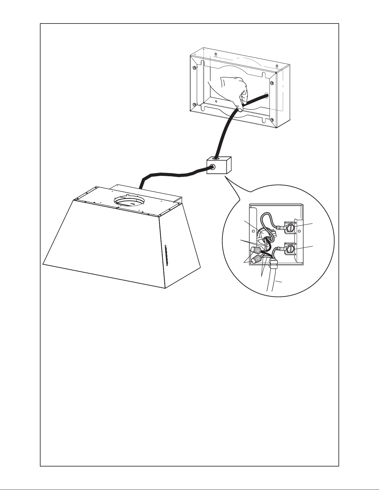
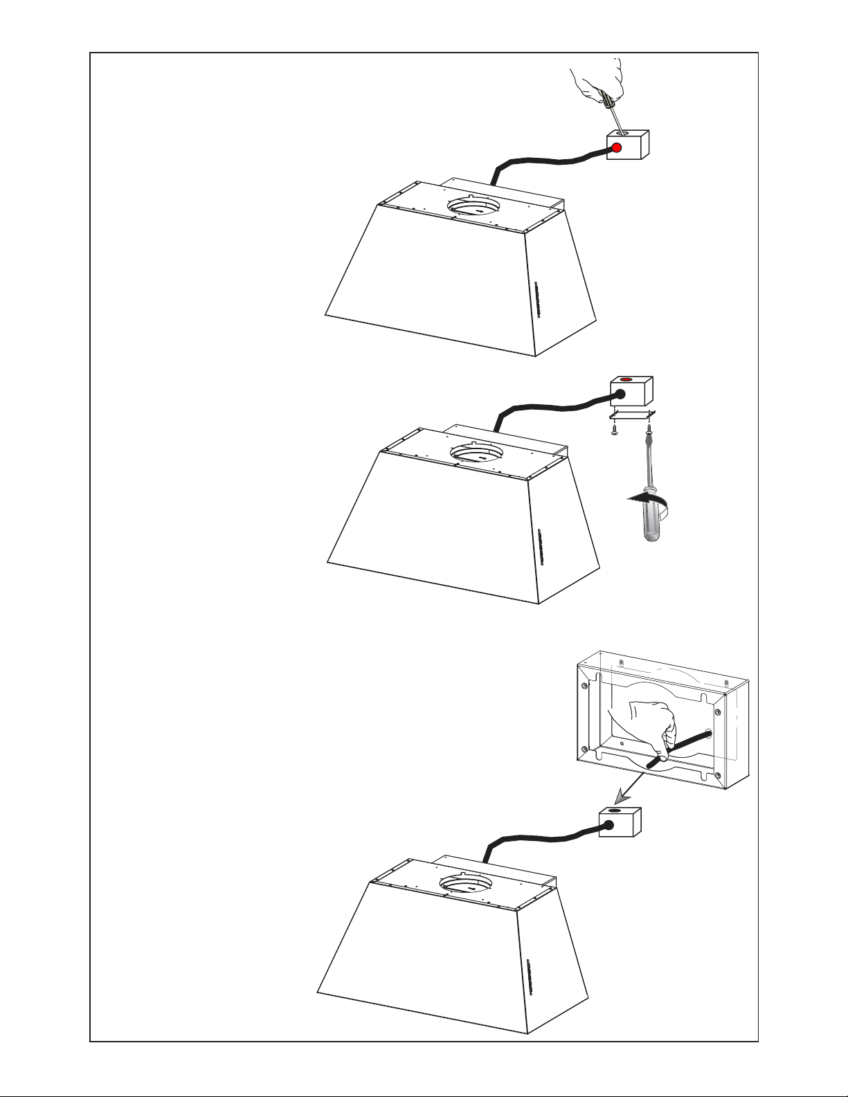
13
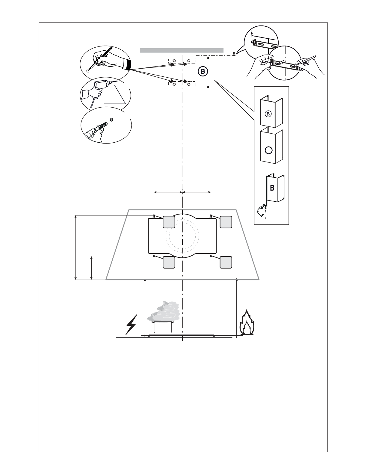
Break the Hole in the Wiring
Box to connect the Hood to
Power Supply Cable.
Pull the cable from the Power
Supply through the Hole for
the Electrical Connection to
the Wiring Box.
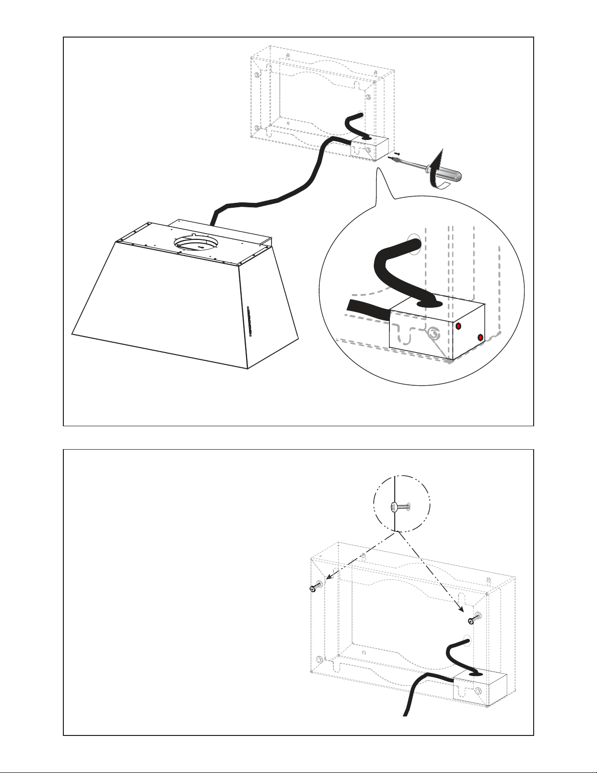
Remove the Wiring Box
compartment cover by
unscrewing the two screws.
14
14
A. Home power supply cable
B. Black wires
C. UL listed wire connectors
D. White wires
E. Green (or bare) ground wire from home power supply connected to green ground screw
F. Range hood power supply cable
G. Green ground wire from Range hood power supply cable connected to green ground screw.
E
A
F
D
C
B
G
Installation of wiring connection
5HPRYHWKHFRYHUIURPWKH¿HOGZLULQJFRPSDUWPHQW
DO NOT turn on the power until installation is complete!
Connect the Power Supply Cable to the rangehood.
Connect the Green (Green and Yellow) ground wire under the Green grounding
screw. Attach the White lead of the power supply to the White lead of the range-
hood with a twist-on type wire connector.
Attach the Black lead of the power supply to the Black lead of the rangehood
with a twist-on type wire connector.
5HSODFHWKH¿HOGZLULQJFRPSDUWPHQWFRYHU
15
15
16
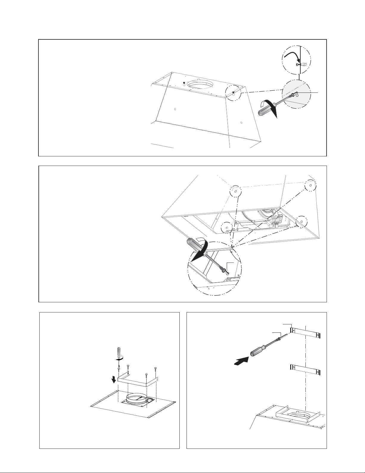
Secure the Wiring Box as shown
in the image with the 2 Screws
(12b).
12b
Attention: After the Wiring Box installation, place the Cable inside a Rear Section without stressing for
the Cable.
12a
Screw the two 12a screws into
the Rear Section with the heads
exposed by 1/4".
16
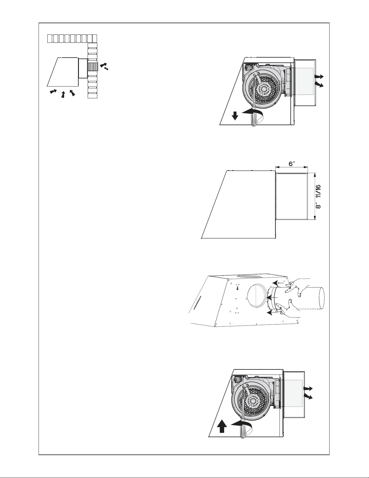
%HIRUH¿[LQJWKH%RG\+RRGWRWKH
Rear Section, Unscrew the 2 screws
WR¿[WKH%ORZHU
This operation will simplify the connect
of Air outlet duct.
E F
D G
[
[
Only for the Rear Ducting Installation
Use this dimensional drawing to help with planning of duct
connection.
Install to the Roof or Wall attach ductwork.
After ¿[LQJWKH%RG\+RRGWRWKH5HDU6HFWLRQ¿[
the Blower in the previously position with the
same 2 screws.
E F
D G
[
[
E F
D G
[
[
17
Complete the Securing of the Hood
Body to the Rear Section by installing
the two remaining 12a screws into
the lower holes on the Rear Section.
Secure all the 4 screws.
18
M1 = 4x
M6x15
M1
4x
19
5HSODFHWKH¿OWHUVLQWRWKHKRRGDQGORFNWKH
security cable as shown in the image to the
right. Close the panel.
17
Hook the hood body onto
the upper screws (12a)
of the mounted Rear
Section, and then fully
secure the screws.
L
2x
12a

18
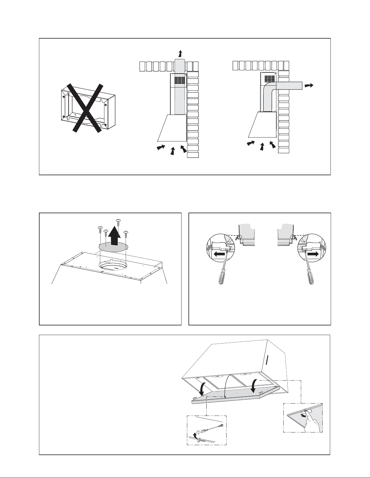
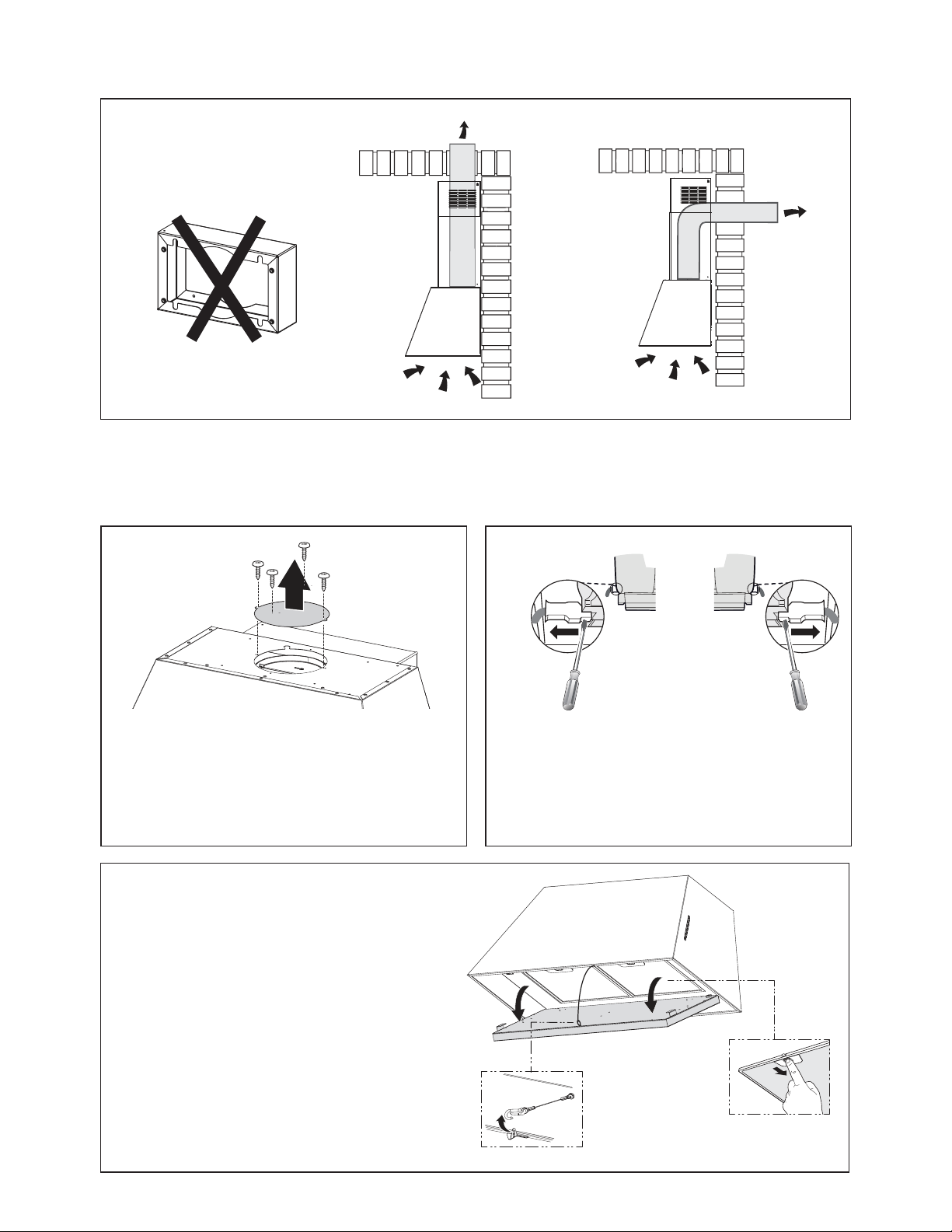
Vertical and Horizontal Ducted Venting Installation with the optional Kit Chimney
Remove the 4 screws as shown and take off the cover plates.
Do not discard and set aside for future use.
)URPLQVLGHWKHKRRGXVHDÀDWKHDGVFUHZGULYHUDV
shown in image above, to disconnect the left and right
Connectors from the blower.
1 2
3
Open the panel, unlock the security cable as shown.
5HPRYHWKH¿OWHUVE\SXVKLQJWKHOHYHUWRZDUGVWKH
back of the unit and at the same time pulling downward.
'RQRWGLVFDUGWKH¿OWHUVDQGVHWDVLGHIRUIXWXUHXVH
Installation with the optional Kit Chimney - Preparation of Hood

19
4
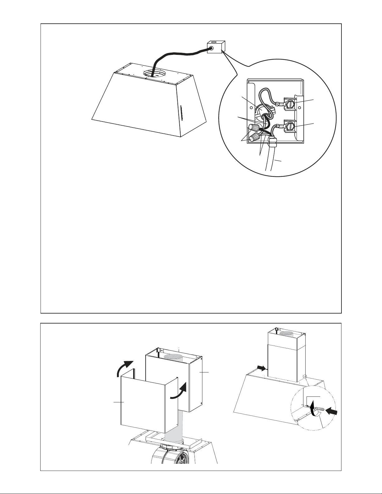
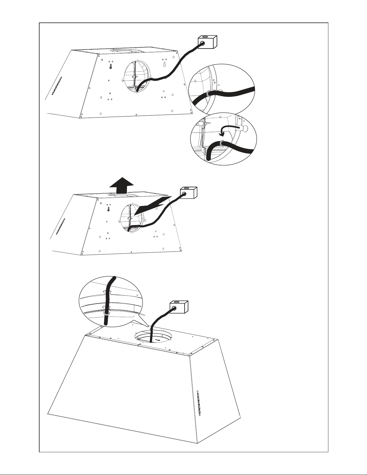
Pull the Cable from
the rear hole.
Fix the Cable in the hole on the Top of the Hood
as show.
Move the Cable from the rear of the
Hood to the Top of the Hood.
20
Re-secure the Cover Plate as shown with the
screws removed previously.
6
5
Unscrew the 2 screws that hold the blower and unlock it from the initial position as shown in Image a.
E F
D G
[
[
After removing blower rotate as shown until it is in the correct rear venting position as shown in Image b-c.
Use the two screws (Posi-Drive) that were removed to secure the blower as shown in Image d.

21
8
Draw a vertical line on the supporting wall as high as practical, at the center of the area in which the hood will be installed.
'UDZDKRUL]RQWDOOLQHDWZKHUHWKHERWWRPHGJHRIWKHKRRGZLOOEHORFDWHGDVLQGLFDWHGLQWKH¿JXUHWKDWLVDPLQLPXP
of 24" above Electric cooking surface and 30" above Gas.
A10
A10
From inside the hood re-connect the Connectors on the left
and right side shown in the image above.
7
Installation with the optional Kit Chimney - Preparation of Wall
22
Mark the wall where indicated (A), 11 9/16" above the horizontal line and at 5 1/8" distance on the left and right of vertical line. Checking that the two
marks are level.
Insert two wall plugs and two screws into the holes as shown not completely (purchased separately).
Mark the wall where indicated (B), 4 1/4" above the horizontal line and at 5 1/8" distance on the left and right of vertical line. Checking that the two
marks are level.
Insert two wall plugs (purchased separately).
Place a bracket 7.2.1 on the wall as shown about 1 1/8" from the ceiling or upper limit, aligning the center (notch) with the vertical reference line and
mark the wall at the centers of the holes in the bracket.
3ODFHWKHVHFRQGEUDFNHWRQWKHZDOODVVKRZQEHORZWKH¿UVWEUDFNHWDWWKHKHLJKWRIWKHXSSHUFKLPQH\VHFWLRQVXSSOLHGDQGDOLJQLQJWKH
center (notch) with the vertical line.
Mark the wall at the centers of the holes in the bracket and drill ø 5/16" as shown.
Installation screws provided for the Brackets, must be secured with wall plugs (purchased separately).
$
´
´
11
9/16”
4
1/4”
5
1/8” 5 1/8”
$
%
$
%
´
>
[
[
´
9

23
10
+RRN DQG ¿[ WKH KRRG ERG\ RQWR
the wall.
From inside fully secure the 4 screws 12a.
L
2x
4
L
4x
11
12
Use the four
screws(included
with Optional Tele-
scopic Chimney
Kit) to secure the
angle bracket.
13
8
L
4x
M
2x
Fix the
bracket using
the screws
included with
Optional
Telescopic
Chimney Kit.
Installation with the optional Kit Chimney

24
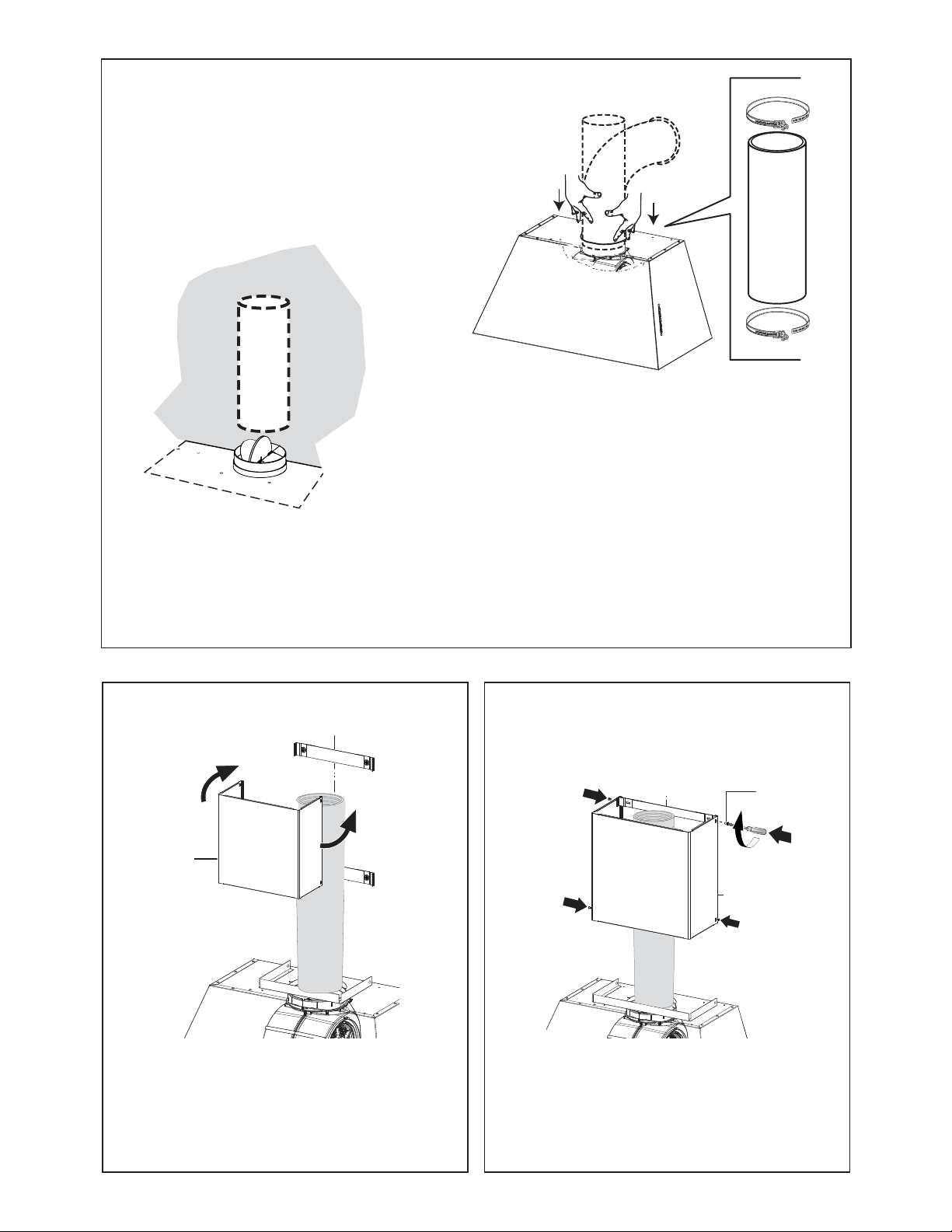
Install Roof or Wall Cap purchased separately. Connect the 6" metal ductwork to the Roof or Wall Cap and
then attach ductwork.
N1
10
B
11
N1
M1
4x
B
Slightly widen the two sides of the upper
chimney and hook them behind the brackets,
making sure that they are well seated.
Secure the sides to the brackets by using the 4
screws .
15 16
14
25
Installation of wiring connection
E
A
F
D
C
B
G
5HPRYHWKHFRYHUIURPWKH¿HOGZLULQJFRPSDUWPHQW
DO NOT turn on the power until installation is complete!
Connect the Power Supply Cable to the rangehood.
Connect the Green (Green and Yellow) ground wire under the
Green grounding screw. Attach the White lead of the power supply
to the White lead of the rangehood with a twist-on type wire con-
nector.
Attach the Black lead of the power supply to the Black lead of the
rangehood with a twist-on type wire connector.
5HSODFHWKH¿HOGZLULQJFRPSDUWPHQWFRYHU
17
A. Home power supply cable
B. Black wires
C. UL listed wire connectors
D. White wires
E. Green (or bare) ground wire from home power supply connected to green ground screw
F. Range hood power supply cable
G. Green ground wire from Range hood power supply cable connected to green ground screw.
12
N2
N1
N
2x
Slightly widen the
two sides of the
lower section and
hook them between
the upper section
and the wall, making
sure that they are
properly housed.
B
A
18
26
USE AND CARE INFORMATION
For Best Results
6WDUWWKHUDQJHKRRGVHYHUDOPLQXWHVEHIRUHFRRNLQJWRGHYHORSSURSHUDLUÀRZ$OORZWKHUDQJHKRRGWRRSHUDWH
for several minutes after cooking is complete to clear all smoke and odors from the kitchen.
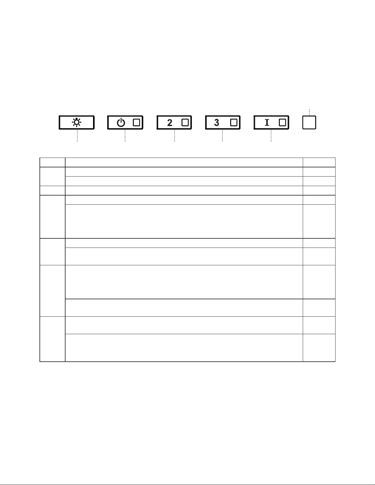
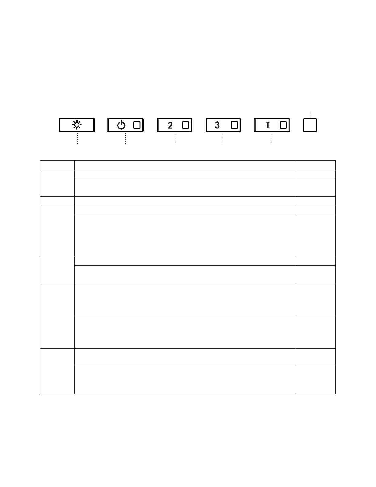
S1
L T1 T2 T3 T4
Button Function Led
L Turns the lights on/off at maximum strength. -
Press and hold the button for approximately 2 seconds to dim the Lights On/Off. -
T1 Turns the motor on/off at speed one. -
T2 Turns the Motor on at speed two. -
Press and hold the button for approximately 5 seconds, with all the loads turned off (Motor and
/LJKWVWRWXUQWKH$FWLYDWHG&KDUFRDO)LOWHUDODUPRQ7KHUHOHYDQW/('ÀDVKHVWZLFHWRFRQ¿UP
To turn the alarm off, press the button again and hold for at least 5 seconds. The relevant LED
ÀDVKHVRQFH
Flashing
T3 Turns the Motor on at speed three. -
Press and hold the button for approximately 3 seconds, with all the loads turned off (Motor and Lights),
WRSHUIRUPDUHVHW7KH/('6ÀDVKHVWKUHHWLPHV
Flashing
T4 Turns the Motor on at INTENSIVE Speed.
This speed is timed to run for 6 minutes. At the end of this time, the system returns automatically to
the speed that was set before. If it is activated with the motor turned off, the hood will switch to OFF
at the end of the time.
-
3UHVVDQGKROGIRUVHFRQGVWRHQDEOHWKHUHPRWHFRQWUROLQGLFDWHGE\WKH/('ÀDVKLQJWZLFH
3UHVVDQGKROGIRUVHFRQGVWRGLVDEOHWKHUHPRWHFRQWUROLQGLFDWHGE\WKH/('ÀDVKLQJMXVWRQFH
Flashing
S1 6LJQDOVWKH0HWDO*UHDVH)LOWHUVDWXUDWLRQDODUPLQGLFDWLQJWKDWLWLVQHFHVVDU\WRZDVKWKH¿OWHUV
The alarm is triggered after the Hood has been in operation for 100 working hours.
Fixed
When this is activated, it signals the Activated Charcoal Filter saturation alarm, indicating that the
¿OWHUPXVWEHFKDQJHGWKH0HWDO*UHDVH)LOWHUVPXVWDOVREHZDVKHG7KH$FWLYDWHG&KDUFRDO)LOWHU
saturation alarm comes into operation after the Hood has been working for 200 hours.
Flashing
27
LED LIGHTING UNIT
• LED lights must be replaced by Faber factory authorized
service.
"KD@MHMFLDS@KFQD@RDkKSDQR
These can be washed in the dishwasher, and need to be cleaned
whenever the S1 Led comes on or at least once every 2 months use,
or more frequently if use is particularly intensive.
Resetting the alarm signal
• Turn the Lights and the Suction Motor off.
• 3UHVV7DQGKROGIRUDWOHDVWVHFRQGVXQWLO/('ÀDVKHV
WKUHHWLPHVLQFRQ¿UPDWLRQ
Cleaning
• 5HPRYHWKH¿OWHUSXVKLQJWKHOHYHUWRZDUGVWKHEDFNRIWKH
unit and at the same time pulling downward.
• :DVKWKH¿OWHUZLWKRXWEHQGLQJLWOHDYHLWWRGU\WKRURXJKO\
EHIRUH UHSODFLQJ LI WKH VXUIDFH RIWKH ¿OWHU FKDQJHV FRORU
RYHUWLPHWKLVZLOOKDYHDEVROXWHO\QRHIIHFWRQLWVHI¿FLHQF\
• Replace, taking care to ensure that the handle faces
forward.
• &OHDQLQJLQGLVKZDVKHUPD\GXOOWKH¿QLVKRIWKHPHWDO
JUHDVH¿OWHU
Replacing Activated Charcoal Filter
This cannot be washed or regenerated, and must be changed when
OHG6VWDUWVWRÀDVKRUDWOHDVWRQFHHYHU\PRQWKV7KH$ODUP
signal, if it has been activated, only appears when the Suction motor
is turned on.
Resetting the alarm signal
• Turn the Lights and the Suction Motor off.
• 3UHVV7DQGKROGIRUDWOHDVWVHFRQGVXQWLO/('ÀDVKHV
WKUHHWLPHVLQFRQ¿UPDWLRQ
Cleaning
• 5HPRYHWKHFKDUFRDO¿OWHUE\URWDWLQJLWFORFNZLVHEDFNZDUGVXQWLOLW
unlocks from the motor housing and pull off sideways.
• 7RUHLQVHUWHDFKFKDUFRDO¿OWHUSODFHXSDJDLQVWWKHVLGHRIWKH
EORZHUDQGSXVKLWLQZDUG7KHQWXUQWKHFKDUFRDO¿OWHUFORFNZLVH
IRUZDUGXQWLOLW¿WVLQWRSODFH
5
Z

28
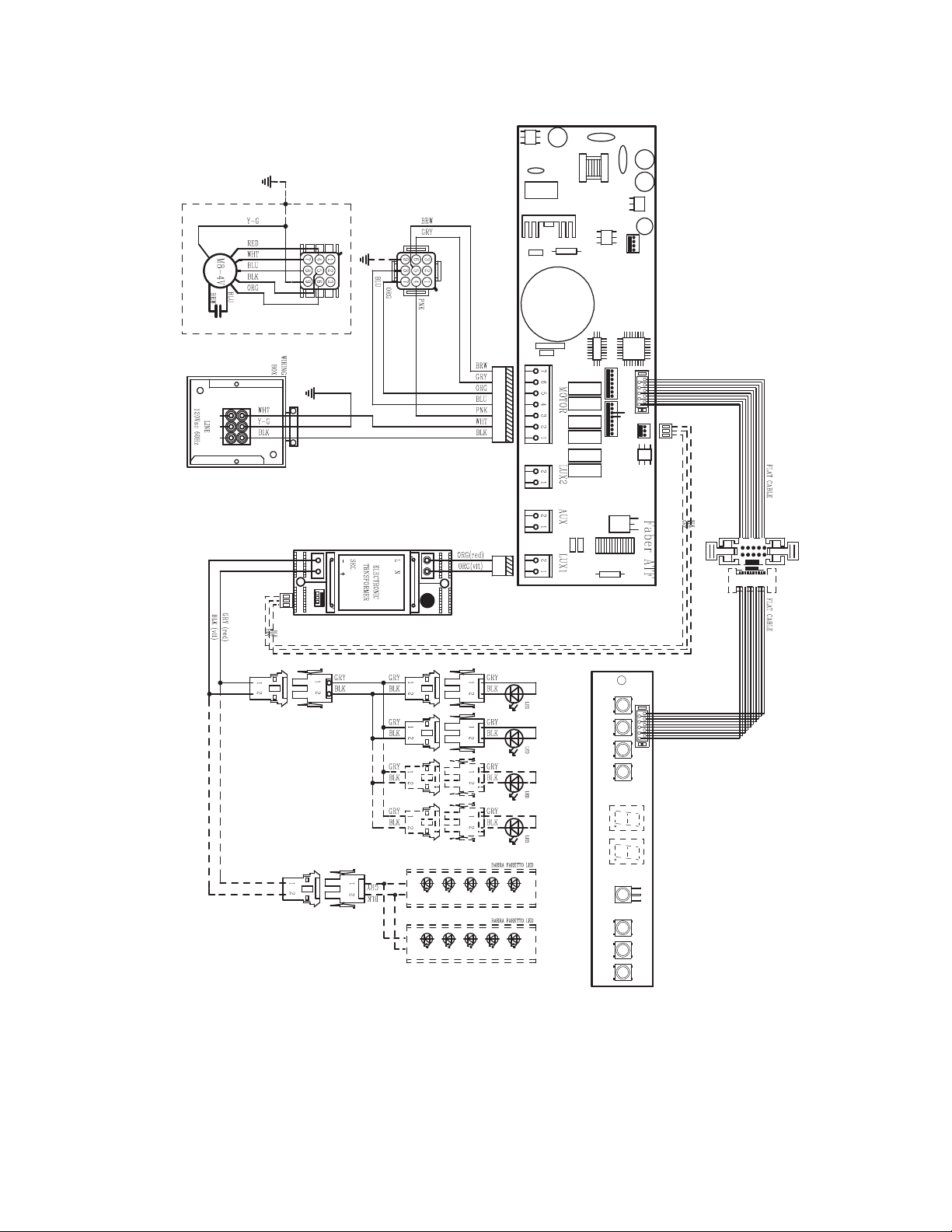
Wiring Diagram
+U
'B
+ U
'B

29
January 4, 2016
FABER CONSUMER WARRANTY & SERVICE
All Faber products are warranted against any defect in materials or workmanship for the original purchaser
for a period of 1 year from the date of original purchase (requires proof of purchase). This warranty covers
labor and replacement parts. Faber, at its option, may repair or replace the product or components
necessary to restore the product to good working condition. To obtain warranty service, contact the dealer
from whom you purchased the range hood, or the local Faber distributor. If you cannot identify a local Faber
distributor, contact us at (508) 358-5353 for the name of a distributor in your area.
The following is not covered by Faber's warranty:
1. Service calls to correct the installation of your range hood, to instruct you how to use your range hood, to
replace or repair house fuses or to correct house wiring or plumbing.
2. Service calls to repair or replace range hood light bulbs, fuses or filters. Those consumable parts are
excluded from warranty coverage.
3. Repairs when your range hood is used for other than normal, single-family household use.
4. Damage resulting from accident, alteration, misuse, abuse, fire, flood, acts of God, improper installation,
installation not in accordance with electrical or plumbing codes or Faber documentation, or use of products
not approved by Faber.
5. Replacement parts or repair labor costs for units operated outside the United States or Canada, including
any non-UL or C-UL approved Faber range hoods.
6. Repairs to the hood resulting from unauthorized modifications made to the range hood.
7. Expenses for travel and transportation for product service in remote locations and pickup and delivery
charges. Faber range hoods should be serviced in the home.
THIS WARRANTY DOES NOT ALLOW RECOVERY OF INCIDENTAL OR CONSEQUENTIAL DAMAGES, INCLUDING, WITHOUT
LIMITATION, DIRECT, INDIRECT, INCIDENTAL, SPECIAL OR CONSEQUENTIAL DAMAGES, PERSONAL INJURY/WRONGFUL
DEATH OR LOST PROFITS FABER WARRANTY IS LIMITED TO THE ABOVE CONDITIONS AND TO THE WARRANTY PERIOD
SPECIFIED HEREIN AND IS EXCLUSIVE. EXCEPT AS EXPRESSLY SPECIFIED IN THIS AGREEMENT, FABER DISCLAIMS ALL
EXPRESS OR IMPLIED CONDITIONS, REPRESENTATIONS, AND WARRANTIES INCLUDING, WITHOUT LIMITATION, ANY
IMPLIED WARRANTIES OF MERCHANTABILITY OR FITNESS FOR A PARTICULAR PURPOSE
.
This warranty gives you specific legal rights that may vary from state to state.
Model#: ______________________________ Serial #: _____________________________

30
VEUILLEZ LIRE ET CONSERVER LA PRÉSENTE NOTICE AVANT DE
COMMENCER L'INSTALLATION DE LA HOTTE DE CUISINE
5$13(22$,$-3/.411Í#4(1$+$1(204$#f4-%$4#$&1 (22$241+ 3 !+$#$"4(22.-Ů
a) Ne laissez jamais sans surveillance les éléments de la surface de cuisson à température élevée. Les
bouillonnements excessifs peuvent provoquer de la fumée et les débordements de graisse peuvent
RfDMl@LLDQ+fGTHKDCNHSģSQDBG@TEEĢDKDMSDLDMSĒTMDSDLOĢQ@STQDA@RRDNTLNXDMMD
b) Assurez-vous de toujours mettre en marche le ventilateur de la hotte lorsque vous cuisinez à tem-
OĢQ@STQDĢKDUĢDNTOQĢO@QDYTMLDSRl@LAĢODWBQģODR2TYDSSDBDQHRDRITAHKĢATEl@LAĢ
c) Nettoyez régulièrement les ventilateurs d'aspiration. Assurez-vous de ne pas laisser de la graisse
Rf@BBTLTKDQRTQKDUDMSHK@SDTQNTKDkKSQD
C4SHKHRDYSNTINTQRCDRONģKDRDSB@RRDQNKDRCDK@S@HKKD@OOQNOQHĢD4SHKHRDYSNTINTQRCDRTRSDMRHKDRCD
cuisine de la taille adaptée à celle de l'élément chauffant.
5$13(22$,$-3Ů/.41/1Í5$-(1+$2!+$2241$2$-" 2#$%$4#$&1 (22$241+ 3 !+$
#$"4(22.-24(5$9+$21$".,, -# 3(.-224(5 -3$2Ů
a) ÉTOUFFEZ LES FLAMMES à l'aide d'un couvercle hermétique, d'une plaque à biscuits ou d'un plateau
métallique, puis éteignez le brûleur. FAITES ATTENTION AUX BRÛLURES. Si le feu ne s'éteint pas
immédiatement, QUITTEZ LES LIEUX ET APPELEZ LES POMPIERS.
b) NE PRENEZ JAMAIS UNE CASSEROLE EN FLAMME - Vous pourriez vous brûler.
c) N'UTILISEZ JAMAIS DE L'EAU, ni un linge à vaisselle ou un torchon mouillé, pour éteindre le feu. Cela
pourrait provoquer une violente explosion de vapeur.
C4SHKHRDYTMDWSHMBSDTQ4-(04$,$-3RHŮ
5NTRģSDRBDQS@HMPTfHKRf@FHSCfTMDWSHMBSDTQCDBK@RRD !"DSPTDUNTRBNMM@HRRDYAHDMRNM
mode d'emploi.
2. Le feu est de faible intensité et se limite à l'endroit où il a démarré.
3. Les pompiers ont déjà été appelés.
4MDUNHDCDRNQSHDRDSQNTUDCDQQHġQDUNTRODMC@MSPTDUNTRĢSDHFMDYKDRl@LLDR
#e@OQĠRKDFTHCDgŰ*HSBGDM%HQDR@EDSX3HORŰuOTAKHġO@QK@-%/ @TWÍS@SR4MHR
AVERTISSEMENT - POUR RÉDUIRE LE RISQUE D'INCENDIE OU DE CHOC ÉLECTRIQUE, n'utilisez
jamais ce ventilateur en association avec un dispositif de réglage de vitesse à semi-conducteurs.
AVERTISSEMENT - POUR RÉDUIRE LES RISQUES D'INCENDIE, DE CHOC ÉLECTRIQUE OU DE
!+$2241$".1/.1$++$1$2/$"3$9+$2(-2314"3(.-224(5 -3$2Ů
1. Utilisez cet appareil uniquement de la façon prévue par le fabricant. Pour toute question, commu-
niquez avec le fabricant.
2. Avant de procéder à l'entretien ou au nettoyage de l'appareil, coupez l'alimentation au niveau du
panneau électrique et verrouillez-le pour vous assurer que l'électricité n'est pas rétablie accidentel-
KDLDMS2fHKMfDRSO@RONRRHAKDCDUDQQNTHKKDQKDCHRONRHSHECfHMSDQQTOSHNMCDKf@KHLDMS@SHNM@EkBGDYCD
façon ferme et bien visible un avis de danger, par exemple à l'aide d'une étiquette sur le panneau.
33$-3(.-Ů#DRSHMĢĒTMTR@FDCDUDMSHK@SHNMFĢMĢQ@KDTMHPTDLDMS-fTSHKHRDYO@RBDCHRONRHSHEONTQ
l'aspiration de vapeurs ou de matériaux dangereux ou explosifs.
AVERTISSEMENT - POUR RÉDUIRE LES RISQUES D'INCENDIE, DE CHOC ÉLECTRIQUE OU DE
!+$2241$".1/.1$++$1$2/$"3$9+$2(-2314"3(.-224(5 -3$2Ů
1. +fHMRS@KK@SHNMDSKDAQ@MBGDLDMSĢKDBSQHPTDCNHUDMSģSQDQĢ@KHRĢRO@QTMSDBGMHBHDMPT@KHkĢDSBNM-
formément à tous les codes et normes en vigueur, incluant ceux concernant la construction à
l'épreuve du feu.
2. kMCDF@Q@MSHQTMDBNLATRSHNMDSTMDĢU@BT@SHNM@CĢPT@SDRCDRF@YO@QKDRBNMCTHSDRCDK@BGD-
minée des appareils à combustion, une bonne aération est nécessaire pour éviter le refoulement.
Respectez les lignes directrices fournies par le fabricant du matériel chauffant, ainsi que les normes
CDRĢBTQHSĢBNLLDBDKKDROTAKHĢDRO@QK@-@SHNM@K%HQD/QNSDBSHNM RRNBH@SHNM-%/ DSK@ LDQHB@M
2NBHDSXENQ'D@SHMF1DEQHFDQ@SHNM@MC HQ"NMCHSHNMHMF$MFHMDDQR 2'1 $@TWÍS@SR4MHR@HMRH
que les codes en vigueur dans votre région.
3. Lorsque vous faites une ouverture ou percez dans un mur ou le plafond, veillez à ne pas endom-
L@FDQKDRkKRĢKDBSQHPTDRNTCf@TSQDRCHRONRHSHERB@BGĢR
4. +DRUDMSHK@SDTQRB@M@KHRĢRCNHUDMSSNTINTQRģSQDQ@BBNQCĢRĒKfDWSĢQHDTQ

31
3.43$.45$1341$# -2+$,41.4+$/+ -"'$1½/1.7(,(3Í#$+ '.33$#.(3
Î31$2"$++Í$
Un espace libre d'au moins 24" est requis entre le bas de la hotte et la surface de cuisson ou le comptoir.
"DSSDGNSSD@ġSġGNLNKNFTġDO@QKe4+ĐBDSSDCHRS@MBDCDK@RTQE@BDCDBTHRRNM
+DRO@BDKHAQDLHMHL@KQDPTHRODTSĢSQDOKTRFQ@MCRDKNMK@QġFKDLDMS@SHNMDML@SHĠQDCDBNMRSQTBSHNMCDUNSQD
QġFHNM/NTQKDRBTHRHMHĠQDRĐF@YDSKDRBTHRHMHĠQDRBNLAHMġDRTMDRO@BDLHMHL@KCDŭDRSQDBNLL@MCġ
DSONTQQ@HSĢSQDDWHFġ
+@OQNENMCDTQL@WHL@KDCDR@QLNHQDRRTRODMCTDRDRSCDŭ+DR@QLNHQDRRTRODMCTDRCDBG@PTDBŃSġ
CDKe@OO@QDHKCNHUDMSRDSQNTUDQĐ@TLNHMRŭCDK@RTQE@BDCDBTHRRNMNTCTBNLOSNHQ"NMRTKSDYK@
notice d'installation de la surface de cuisson ou de la cuisinière fournie par le fabricant avant de pratiquer
des ouvertures.
(-23 ++ 3(.-# -24-$, (2.-,.!(+$+eHMRS@KK@SHNMCDBDSSDGNSSDCNHSĢSQDBNMENQLDĐK@/@QSHD
CDK@MNQLD,@MTE@BSTQDC'NLD"NMRSQTBSHNM@MC2@EDSX2S@MC@QCR3HSKD"%1OQġBġCDLLDMS
la partie 280 de la norme Federal Standard for Mobile Home Construction and Safety, Title 24, HUD).
"NMRTKSDYK@jBGDSDBGMHPTDġKDBSQHPTD
CRITÈRES DE VENTILATION
#ġSDQLHMDYPTDKKDLġSGNCDCDUDMSHK@SHNMDRSLHDTW@C@OSġDĐUNSQD@OOKHB@SHNM+DRBNMCTHSRODTUDMS
passer par le mur ou le toit.
/NTQF@Q@MSHQTMDLDHKKDTQDDEjB@BHSġK@KNMFTDTQCDRBNMCTHSRDSKDMNLAQDCDBNTCDRCNHUDMSĢSQDKDOKTR
KHLHSġRPTDONRRHAKD+DCH@LĠSQDCDRBNMCTHSRCDUQ@HSĢSQDTMHENQLD-eHMRS@KKDYO@RCDTWBNTCDRDMRDL-
AKD4SHKHRDYTMQTA@MONTQB@M@KHR@SHNMR@jMCDRBDKKDQSNTRKDRINHMSRCTRXRSĠLDCDBNMCTHSR4SHKHRDYTM
B@KEDTSQ@FDONTQRBDKKDQKDRNTUDQSTQDRC@MRKDLTQDWSġQHDTQNTKDOK@MBGDQ@TSNTQCTBK@ODS
(KMfDRSO@RQDBNLL@MCĢCfTSHKHRDQCDRBNMCTHSRlDWHAKDR+DRBNMCTHSRlDWHAKDROQNUNPTDMSTMD
BNMSQDOQDRRHNMDSCDK@STQATKDMBDPTHCHLHMTDMSFQ@MCDLDMSKfDEkB@BHSĢCDKf@OO@QDHK
RRTQDYUNTRPTDKeDRO@BDKHAQDC@MRKDLTQNTKDOK@MBGDQDRSRTEjR@MSONTQKDBNMCTHSCeġU@BT@SHNM@U@MSCD
OQ@SHPTDQKDRNTUDQSTQDR-DBNTODYI@L@HRTMDONTSQDNTTMBGDUQNMR@TERHBeDRS@ARNKTLDMSMġBDRR@HQD
2eHKRe@UĠQDMġBDRR@HQDCDBNTODQTMDONTSQDNTTMBGDUQNMK@BNMRSQTBSHNMCeTMQDMENQBDLDMSDRSQDPTHRD
AVERTISSEMENT - Pour réduire le risque d'incendie, utilisez uniquement des conduits métalliques.
ATTENTION - Pour réduire le risque d'incendie et pour évacuer adéquatement l'air, assurez-vous
CDQ@BBNQCDQKDRBNMCTHSRĒKfDWSĢQHDTQm-DCHEETRDYO@RKf@HQCfĢU@BT@SHNMC@MRCDRDRO@BDRĒ
l'intérieur des murs ou du plafond, ou encore à l'intérieur d'un grenier, d'une galerie technique
ou d'un garage.
Installation dans les climats froids
+DRXRSĠLDCDUDMSHK@SHNMCNHSOQġUNHQTMQDFHRSQD@MSHQDENTKDLDMSRTOOKġLDMS@HQDONTQQġCTHQDKDkTWCe@HQEQNHC
HMUDQRD@HMRHPTeTMDA@QQHĠQDSGDQLHPTDONTQQġCTHQDK@BNMCTBSHNMCDRSDLOġQ@STQDRDWSġQHDTQDR+DQDFHRSQD
CNHSĢSQDHMRS@KKġCTBŃSġ@HQEQNHCO@QQ@OONQSĐK@A@QQHĠQDSGDQLHPTD+@A@QQHĠQDSGDQLHPTDCNHSĢSQDONRHSHNMMġD
KDOKTROQĠRPTDONRRHAKDCDKeDMCQNHSNŔKDRXRSĠLDCDUDMSHK@SHNMOġMĠSQDC@MRK@O@QSHDBG@TEEġDCDK@L@HRNM
q+DRXRSĠLDCDUDMSHK@SHNM#.(3CġANTBGDQĐKeDWSġQHDTQ
• NE FAITES PASCġANTBGDQKDRBNMCTHSRC@MRTMFQDMHDQNTTM@TSQDDMCQNHSEDQLġ
• N'UTILISEZ PASTMBK@ODSCDRġBGDTRDLTQ@KCDŰŭ
q(KMeDRSO@RQDBNLL@MCġCeTSHKHRDQCDRBNMCTHSRkDWHAKDR
• N'ENTRAVEZ PASKDkTWCDKe@HQCDBNLATRSHNMDSCDUDMSHK@SHNM
• Le non-respect des exigences en matière de ventilation pourrait entraîner un incendie.
AVERTISSEMENT
!
32
FICHE TECHNIQUE ÉLECTRIQUE
4MD@KHLDMS@SHNMCDBNTQ@MS@KSDQM@SHECDUNKSRĐŰ'YDRSQDPTHRDRTQTMBHQBTHSĐ
ETRHAKDCHRSHMBSCD@LOĠQDR(KDRSQDBNLL@MCġCeHMRS@KKDQTMETRHAKDSDLONQHRġNT
TMCHRINMBSDTQ+DETRHAKDCNHSĢSQDB@KHAQġBNMENQLġLDMS@TWBNCDRDMUHFTDTQONTQKDR
B@Q@BSġQHRSHPTDRMNLHM@KDRġKDBSQHPTDRCDKe@OO@QDHKHMCHPTġDRRTQK@OK@PTDRHFM@KġSHPTD
RHSTġDĐKeHMSġQHDTQCDKe@OO@QDHKĐOQNWHLHSġCTBNLO@QSHLDMSCDRBĒAK@FDRDWSDQMDR
INSTALLATION ÉLECTRIQUE AVEC BOÎTIER DE CONNEXION
"$3 // 1$(+#.(3Î31$4-(04$,$-3!1 -"'ͽ+e (#$#$%(+2#$"4(51$
+DB@KHAQDCDRjKRCNHSĢSQDBNMENQLD@TWBQHSĠQDRCDK@CDQMHĠQDġCHSHNMCT-@SHNM@K
$KDBSQHB@K"NCDCDKe -2(-%/ DSCDKeDMRDLAKDCDRBNCDRDSQġFKDLDMS@SHNMRDM
UHFTDTQ+DB@KHAQDCDRjKRDSKDRBNMMDWHNMRCNHUDMSĢSQD@C@OSġR@TWB@Q@BSġQHRSHPTDR
nominales de l'appareil. Il est possible de se procurer un exemplaire des normes in-
CHPTġDRBHCDRRTRDMBNLLTMHPT@MS@UDBŰ
National Fire Protection Association
Batterymarch Park
0THMBX,@RR@BGTRDSSRÍS@SR4MHR
"DS@OO@QDHKCDUQ@HSĢSQDAQ@MBGġCHQDBSDLDMS@TRDBSHNMMDTQĐETRHAKDNT@TCHRINMB-
SDTQO@QTMBĒAKDkDWHAKDCDBTHUQD@UDBAKHMC@FDNTF@HMDMNMLġS@KKHPTD+@HRRDYTM
ODTCDIDTC@MRKDBĒAKDONTQODQLDSSQDKDCġOK@BDLDMSCDKe@OO@QDHKRHCDRSQ@U@TW
CeDMSQDSHDMRe@UġQ@HDMSMġBDRR@HQDR4MQ@BBNQCCDBNMCTHSGNLNKNFTġO@QKe4+CDŭ
CNHSĢSQDHMRS@KKġ@TWCDTWDWSQġLHSġRCTBĒAKDCe@KHLDMS@SHNM@TMHUD@TCDKe@OO@QDHK
et de la boîte de liaison).
+NQRCDK@Qġ@KHR@SHNMCTAQ@MBGDLDMSġKDBSQHPTDQġ@KHRDYTMSQNTCDŰŭC@MRKD
LTQ2eHKRe@FHSCeTMSQNTC@MRKDANHRHKCNHSĢSQDONMBġONTQKDQDMCQDKHRRD2eHKRe@FHS
CeTMSQNTC@MRKDLġS@KTMO@RRDjKRDRSQDPTHR
q4MDLHRDĐK@SDQQDġKDBSQHPTDDRSQDPTHRDONTQBDSSDGNSSD
q-e43(+(2$9/ 2TMSTX@TCeD@TEQNHCDONTQK@LHRDĐK@SDQQDRHBDKTHBHDRSAQ@MBGġO@QCDR
INHMSRDMOK@RSHPTDO@QCDRQNMCDKKDRMNMLġS@KKHPTDRNTCe@TSQDRL@SġQH@TW
q-e43(+(2$9/ 2TMDBNMCTHSDCDF@YONTQK@LHRDĐK@SDQQD
q-e(-23 ++$9/ 2TMETRHAKDRTQKDBHQBTHSMDTSQDNTKDBHQBTHSCDLHRDĐK@SDQQD+@OQġRDMBD
CeTMETRHAKDC@MRKDBHQBTHSMDTSQDNTCDLHRDĐK@SDQQDODTSDMSQ@ıMDQTMBGNBġKDBSQHPTD
q"NMRTKSDYTMġKDBSQHBHDMPT@KHjġRHUNTRMeĢSDRO@RBDQS@HMCDK@LHRDĐK@SDQQDCDK@GNSSD
q+DMNMQDRODBSCDRDWHFDMBDRCDK@jBGDSDBGMHPTDġKDBSQHPTDONTQQ@HSDMSQ@ıMDQTMHMBDMCHD
AVERTISSEMENT
!

33
DIMENSIONS DE LA HOTTE
´
´
7-11/16"
7 11/16"
INSTALLATION AVEC VENTILATION CANALISÉE ARRIÈRE
K@GNSSDCDUQ@HSģSQDKHUQĢD@UDBBDSSDBNMkFTQ@SHNM
34
Min. 24" Min. 30"
35
Accessoires disponibles
Trousse d'évent de recyclage - Filtre à charbon actif - no d’article FILTER1
7URXVVHGH¿OWUHjFKDUERQORQJXHGXUpHODYDEOHQRG¶DUWLFOH),/7(5//
Trousse de cheminée télescopique accessoire - Conduit de cheminée supérieur et inférieur pour
ventilation canalisée ou avec recyclage - no d’article CHIMCHGR - gris / no d’article CHIMCHBK - noir
7pOpFRPPDQGHVDQV¿ODFFHVVRLUH5(0&75/
Réducteur de débit (600 à 400) - no d’article CFMRED-2
Réducteur de débit (600 à 300) - no d’article CFMRED
Pièces requises
- Conduit métallique 6" circulaire.
PIÈCES PRINCIPALES
Composants
Réf. Qté Composants du produit
1 1 Bâti de la hotte, avec : Commandes, éclai
UDJHV¿OWUHVYHQWLODWHXU
2 1 section arrière
8 1 Grille d'évent de recyclage
10 1 Registre ø 5 7/8"
Réf. Qté Composants d'installation
12a 4 Vis 1/4" x 9/16"
12b 2 vis 1/8"x3/8" (pour montage du boîtier de
connexion)
12e 2 Vis 1/8"x3/8" (pour recyclage pour montage
de la grille de ventilation)
Qté Documentation
1 Mode d'emploi
10
1
12a
2
H
I
12b
36
Choisissez la méthode de canalisation
Option sans canalisation, avec
recyclage d’air
Options d'installation avec
ventilation canalisée
Exige l'achat de l'accessoire à charbon actif
Horizontale
Verticale
6"
Pour réduire le risque d’incendie ou de
choc électrique, lorsque l’appareil est utilisé
en mode recyclage, utiliser uniquement le
modèle FILTER1 en guise de trousse de
conversion.
Arrière
L’achat de la cheminée accessoire est requis
46
Installation avec ventilation canalisée verticale et horizontale, avec la
trousse de cheminée en option
6"
6"
37 37
37
1
2
Tracez une ligne verticale sur le mur d'appui le plus haut que possible, au centre de l'emplacement où la hotte sera installée.
Tracez une ligne horizontale à l'endroit correspondant au bas de la hotte comme représenté dans l'illustration. Cet
emplacement doit se trouver à au moins 24" de la surface de cuisson, si elle est électrique, ou à 30" si elle est au gaz.
Tracez un repère sur le mur à l'endroit indiqué (A), 11 9/16" au-dessus de la ligne horizontale et à la distance de 4 5/16" à
GURLWHHWjJDXFKHGHODOLJQHYHUWLFDOH9pUL¿H]VLOHVGHX[PDUTXHVVRQWjpJDOLWp
Insérez deux chevilles et les vis (achetées séparément) dans les trous (A) en laissant libre 1/4" des vis.
Tracez un repère sur le mur à l'endroit indiqué (B), 4 1/4" au-dessus de la ligne horizontale et à la distance de 4 5/16" à
GURLWHHWjJDXFKHGHODOLJQHYHUWLFDOH9pUL¿H]VLOHVGHX[PDUTXHVVRQWjpJDOLWp
Insérez deux chevilles (achetées séparément).
Notice d'installation
Installation de la section arrière
´
´
11
9/16”
4
1/4”
4
5/16” 4 5/16”
$
%
$
%
38
3
Engagez la section arrière sur les vis du haut, comme
LOOXVWUpVXUO¶LPDJHFLGHVVXVHW¿[H]ODIHUPHPHQW
Depuis l’intérieur, vissez à fond les deux vis inférieures
(achetées séparément).
4
L
2x
L
2x
5
Ouvrez le panneau et dégagez le câble
de retenue comme illustré. Retirez les
¿OWUHVHQSRXVVDQWVLPXOWDQpPHQWOHOHYLHU
vers l'arrière de l'appareil et en le tirant
YHUVOHEDV1HMHWH]SDVOHV¿OWUHVPDLV
conservez-les pour plus tard.
Pour option sans canalisation,
avec recyclage d'air
41
Installation avec
canalisation vers l'arrière
39
Retirez les 4 vis comme illustré et enlevez les plaques
GH UHFRXYUHPHQW 1H OHV MHWH] SDV JDUGH]OHV SRXU
utilisation ultérieure.
Depuis l’intérieur de la hotte, utilisez un tournevis à lame
plate comme illustré pour débrancher les connecteurs de
gauche et de droite du ventilateur.
6
Dévissez les 2 vis (Posi-
Drive) qui retiennent le
ventilateur et déverrouillez-
le de sa position initiale,
comme illustré sur
l’image A.
E F
D G
[
[
Après avoir retiré le
ventilateur, tournez-le
FRPPHLOOXVWUpMXVTX¶jTX¶LO
se trouve dans la position
correcte de ventilation
arrière, comme illustré sur
les images B-C.
Utilisez les deux vis qui ont
pWpUHWLUpHVSRXU¿[HUOH
ventilateur, comme illustré
sur l’image D.
7
8
P
P1
2x
Fixez la grille d’évent de recyclage à l’aide de
deux vis.
9
12e
40
A10
Fixez la plaque de recouvrement à l’aide des 4 vis retirées
SUpFpGHPPHQWHWIDLWHVSDVVHUOH¿OGXERvWLHUGHFRQQH[LRQ
à l’extérieur du bâti de la hotte par l’encoche de la plaque
de recouvrement.
)L[H]OHV¿OWUHVjFKDUERQjODJULOOHQRLUHGHFKDTXHF{WpGX
YHQWLODWHXU3UHVVH]IHUPHPHQWOH¿OWUHjFKDUERQFRQWUHODJULOOH
QRLUHGHFKDTXHF{WpGXYHQWLODWHXUHWIDLWHVWRXUQHUOH¿OWUH
dans le sens des aiguilles d'une montre (vers l'avant de la hotte)
MXVTXjFHTXLOVRLWYHUURXLOOpHQSODFH)DLWHVWRXUQHUGDQVOH
sens contraire des aiguilles d'une montre (vers l'arrière de la
hotte) pour l'enlever.
Filtre à charbon actif accessoire requis - no
d'article - FILTER1 (acheté séparément)
A10
10
11 12
Depuis l’intérieur de la hotte, rebranchez les
connecteurs de gauche et de droite illustrés sur
l’image ci-dessus.

41
13
'pIRQFH]O¶RUL¿FHGXERvWLHU
de connexion pour brancher
le câble reliant la hotte à
l’alimentation.
Tirez le câble de l’alimentation
par le trou permettant le
raccord électrique du boîtier
de connexion.
Retirez le couvercle du
compartiment du boîtier de
connexion en dévissant les
deux vis.

42
14
A. Câble d'alimentation du réseau domestique
B. Fils noirs
&6HUUH¿OVKRPRORJXp8/
D. Fils blancs
()LOGHPLVHjODWHUUHYHUWRX¿OQXGHODOLPHQWDWLRQGRPHVWLTXHEUDQFKpjODYLVGHPLVH
à la terre verte
F. Câble d'alimentation de la hotte
G. Fil de mise à la terre vert du câble d'alimentation de la hotte branché à la vis de mise à la
terre verte.
E
A
F
D
C
B
G
Réalisation des branchements
Retirez le couvercle du compartiment des câblages externes.
NE METTEZ PAS l'alimentation sous tension avant d'avoir terminé l'installation!
Branchez le câble d'alimentation à la hotte.
%UDQFKH]OH¿OYHUWYHUWHWMDXQHGHPLVHjODWHUUHVRXVODYLVGHPLVHjOD
WHUUHYHUWH%UDQFKH]OH¿OEODQFGHODOLPHQWDWLRQDX¿OEODQFGHODKRWWHjODLGH
d'un connecteur verrouillé par rotation.
%UDQFKH]OH¿OQRLUGHODOLPHQWDWLRQDX¿OQRLUGHODKRWWHjODLGHGXQFRQQHF-
teur verrouillé par rotation.
Remettez en place le couvercle du compartiment des câblages externes.

43
15
16
Fixez le boîtier de connexion
comme illustré sur l’image à
l’aide des 2 vis (12b).
12b
Attention : Après l’installation du boîtier de connexion, placez le câble dans une section arrière, sans
contrainte sur le câble.
12a
Vissez les deux vis 12a dans la
section arrière en laissant 1/4"
de la tête des vis libre.

44
$YDQWGH¿[HUOHEkWLGHODKRWWH
sur la section arrière, dévissez les
YLV¿[DQWOHYHQWLODWHXU
&HWWHPHVXUHVLPSOL¿HUDOH
raccord de la canalisation de
sortie d’air.
E F
D G
[
[
Pour l’installation avec canalisation arrière
uniquement
8WLOLVH]FHSODQGLPHQVLRQQHOSRXUYRXVDLGHUjSODQL¿HUOH
raccord des canalisations.
Raccordez le dispositif aux canalisations du
plafond ou du mur.
Après DYRLU¿[pOHEkWLGHODKRWWHjODVHFWLRQ
arrière, ¿[H]OHYHQWLODWHXUGDQVVDSRVLWLRQ
précédente avec les 2 mêmes vis.
E F
D G
[
[
E F
D G
[
[

45
Fixez complètement le bâti de la hotte
sur la section arrière en installant les
deux vis 12a restantes dans les deux
trous inférieurs sur la section arrière.
Vissez les 4 vis.
18
M1 = 4x
M6x15
M1
4x
19
5HPHWWH]OHV¿OWUHVHQSODFHGDQVODKRWWH
et verrouillez le câble de retenue comme
illustré dans l’image à droite. Refermez
le panneau.
17
Engagez le bâti de la
hotte sur les vis du haut
(12a) de la section arrière
montée, puis vissez-les
fermement.
L
2x
12a
46
Installation avec ventilation canalisée verticale et horizontale, avec la
trousse de cheminée en option
Retirez les 4 vis comme illustré et enlevez les plaques
GH UHFRXYUHPHQW 1H OHV MHWH] SDV JDUGH]OHV SRXU
utilisation ultérieure.
Depuis l’intérieur de la hotte, utilisez un tournevis
à lame plate comme illustré pour débrancher les
connecteurs de gauche et de droite du ventilateur.
1 2
3
Ouvrez le panneau et dégagez le câble de retenue
FRPPH LOOXVWUp 5HWLUH]OHV ¿OWUHVHQ SRXVVDQW
simultanément le levier vers l'arrière de l'appareil
HWHQOHWLUDQWYHUVOHEDV1HMHWH]SDVOHV¿OWUHV
mais conservez-les pour plus tard.
Installation avec la trousse de cheminée en option - Préparation de la
hotte
47
4
Tirez le câble du
trou arrière.
Fixez le câble dans le trou du haut de la
hotte comme illustré.
Déplacez le câble de l’arrière de la
hotte vers le haut de la hotte.
48
Remettez en place la plaque de
recouvrement comme illustré à l’aide des
vis enlevées précédemment.
6
5
Dévissez les 2 vis qui retiennent le ventilateur et déverrouillez-le de sa position initiale, comme illustré sur l’image A.
E F
D G
[
[
$SUqVDYRLUUHWLUpOHYHQWLODWHXUWRXUQH]OHFRPPHLOOXVWUpMXVTX¶jTX¶LOVHWURXYHGDQVODSRVLWLRQFRUUHFWHGH
ventilation arrière, comme illustré sur les images B-C.
8WLOLVH]OHVGHX[YLV3RVL'ULYHTXLRQWpWpUHWLUpHVSRXU¿[HUOHYHQWLODWHXUFRPPHLOOXVWUpVXUO¶LPDJH'

49
8
Tracez une ligne verticale sur le mur d'appui le plus haut que possible, au centre de l'emplacement où la hotte sera installée.
Tracez une ligne horizontale à l'endroit correspondant au bas de la hotte comme représenté dans l'illustration. Cet
emplacement doit se trouver à au moins 24" de la surface de cuisson, si elle est électrique, ou à 30" si elle est au gaz.
A10
A10
Depuis l’intérieur de la hotte, rebranchez les
connecteurs de gauche et de droite illustrés sur
l’image ci-dessus.
7
Installation avec la trousse de cheminée en option - Préparation du mur
50
Tracez un repère sur le mur à l'endroit indiqué (A), 11 9/16" au-dessus de la ligne horizontale et à une distance de 5 1/8" à droite
HWjJDXFKHGHODOLJQHYHUWLFDOH9pUL¿H]VLOHVGHX[PDUTXHVVRQWjpJDOLWp
Insérez deux chevilles et deux vis dans les trous comme illustré et non complètement (achetées séparément).
Tracez un repère sur le mur à l'endroit indiqué (B), 4 1/4" au-dessus de la ligne horizontale et à une distance de 5 1/8" à droite
HWjJDXFKHGHODOLJQHYHUWLFDOH9pUL¿H]VLOHVGHX[PDUTXHVVRQWjpJDOLWp
Insérez deux chevilles (achetées séparément).
Placez une bride 7.2.1 sur le mur comme illustré, à environ 1 1/8" du plafond ou de la limite supérieure, en alignant le centre
(encoche) avec la ligne de référence verticale. Marquez l'emplacement du centre des trous du support sur le mur.
Placez la deuxième bride 7.2.1 sur le mur comme illustré, sous la première bride, à la hauteur de la section supérieure de la
cheminée fournie et alignez son centre (l’encoche) avec la ligne verticale.
Marquez l'emplacement du centre des trous de la bride sur le mur et percez des trous de ø 5/16" comme illustré.
Les vis d'installation fournies pour les brides doivent être renforcées par des chevilles (achetées séparément).
$
´
´
11
9/16”
4
1/4”
5
1/8” 5 1/8”
$
%
$
%
´
>
[
[
´
9
51
10
(QJDJH]HW¿[H]OHEkWLGHODKRWWH
sur le mur.
Depuis l’intérieur, vissez à fond les 4 vis 12a.
L
2x
4
L
4x
11
12
Utilisez les quatre
vis (incluses avec
la trousse de
cheminée télesco-
pique en option)
SRXU¿[HUO¶pWULHU
d’assemblage.
13
8
L
4x
M
2x
Fixez l’étrier
à l’aide des
vis incluses
avec la trousse
de cheminée
télescopique
en option.
Installation avec la trousse de cheminée en option
52
Installez le clapet de toiture ou le clapet mural acheté séparément. Raccordez le conduit métallique de 6"
au clapet de toiture ou au clapet mural, puis raccordez les conduits.
N1
10
B
11
N1
M1
4x
B
eFDUWH]OpJqUHPHQWOHVGHX[F{WpVGHODFKH-
minée supérieure et engagez-les à l’arrière des
brides, en vous assurant qu'ils sont solidement
ancrés.
)L[H]OHVF{WpVDX[EULGHVjODLGHGHVYLV
15 16
14

53
Réalisation des branchements
E
A
F
D
C
B
G
Retirez le couvercle du compartiment des câblages externes.
NE METTEZ PAS l'alimentation sous tension avant d'avoir terminé
l'installation!
Branchez le câble d'alimentation à la hotte.
%UDQFKH]OH¿OYHUWYHUWHWMDXQHGHPLVHjODWHUUHVRXVODYLVGH
PLVHjODWHUUHYHUWH%UDQFKH]OH¿OEODQFGHODOLPHQWDWLRQDX¿O
blanc de la hotte à l'aide d'un connecteur verrouillé par rotation.
17
A. Câble d'alimentation du réseau domestique
B. Fils noirs
&6HUUH¿OVKRPRORJXp8/
D. Fils blancs
()LOGHPLVHjODWHUUHYHUWRX¿OQXGHODOLPHQWDWLRQGRPHVWLTXHEUDQFKpjODYLVGHPLVH
à la terre verte
F. Câble d'alimentation de la hotte
G. Fil de mise à la terre vert du câble d'alimentation de la hotte branché à la vis de mise à la
terre verte.
12
N2
N1
N
2x
Écartez légèrement
OHVGHX[F{WpVGHOD
section inférieure et
assemblez-les entre
la section supérieure
et le mur, en vous
assurant qu'ils
sont correctement
installés.
B
A
18
%UDQFKH]OH¿OQRLUGHODOLPHQWDWLRQDX¿OQRLUGHODKRWWHjODLGHGXQFRQQHFWHXUYHUURXLOOpSDUURWDWLRQ
Remettez en place le couvercle du compartiment des câblages externes.
54
INFORMATIONS POUR L'UTILISATION ET L'ENTRETIEN
Pour de meilleurs résultats
$FWLYH]ODKRWWHTXHOTXHVPLQXWHVDYDQWGHFRPPHQFHUjFXLVLQHUSRXUFUpHUXQÀX[GDLUDGpTXDW/DLVVH]ODKRWWH
IRQFWLRQQHUTXHOTXHVPLQXWHVDSUqVDYRLU¿QLGHFXLVLQHUSRXUDEVRUEHUWRXWHODIXPpHHWOHVRGHXUVGHODFXLVLQH
S1
L T1 T2 T3 T4
Bouton Fonction DEL
L Allume/Éteint l'éclairage à la puissance maximale. -
Appuyez sur le bouton et tenez-le enfoncé pendant environ 2 secondes pour allumer/éteindre
progressivement l’éclairage.
-
T1 Allume et éteint le moteur à la vitesse un. -
T2 Allume le moteur à la vitesse deux. -
Appuyez sur ce bouton et tenez-le enfoncé pendant environ 5 secondes, lorsque tous les
GLVSRVLWLIVVRQWpWHLQWVPRWHXUHWpFODLUDJHSRXUDFWLYHUODODUPHGX¿OWUHjFKDUERQDFWLI/H
WpPRLQ'(/DSSURSULpFOLJQRWHGHX[IRLVSRXUFRQ¿UPHU
Pour éteindre l'alarme, appuyez de nouveau sur le bouton et tenez-le enfoncé pendant au
moins 5 secondes. Le témoin DEL approprié clignote une fois.
Clignotant
T3 Allume le moteur à la vitesse trois. -
Appuyez sur ce bouton et tenez-le enfoncé pendant environ 3 secondes, lorsque tous les
dispositifs sont éteints (moteur et éclairage), pour réinitialiser. Le témoin DEL S1 clignote trois fois.
Clignotant
T4 Allume le moteur à la vitesse INTENSIVE.
Cette vitesse est programmée pour fonctionner pendant 6 minutes. Après ce délai, le système
retournera automatiquement à la vitesse sélectionnée précédemment. Si cette modalité est
activée tandis que le moteur est éteint, la hotte s'éteindra après le délai.
-
$SSX\H]VXUFHERXWRQHWWHQH]OHHQIRQFpSHQGDQWVHFRQGHVSRXUDFWLYHUODWpOpFRPPDQGH
le témoin DEL clignotera deux fois.
Appuyez sur ce bouton et tenez-le enfoncé pendant 5 secondes pour désactiver la
WpOpFRPPDQGHOHWpPRLQ'(/FOLJQRWHUDXQHVHXOHIRLV
Clignotant
S1 /DODUPHGHVDWXUDWLRQGX¿OWUHjJUDLVVHPpWDOOLTXHVLJQDOHTXLOHVWQpFHVVDLUHGHQHWWR\HU
OHV¿OWUHV/DODUPHVDFWLYHORUVTXHODKRWWHDpWpHQIRQFWLRQSHQGDQWKHXUHV
Fixe
/RUVTXHOOHHVWDFWLYpHODODUPHGHVDWXUDWLRQGX¿OWUHjFKDUERQDFWLIVLJQDOHTXHOH¿OWUHGRLW
rWUHFKDQJp/HV¿OWUHVjJUDLVVHPpWDOOLTXHVGRLYHQWpJDOHPHQWrWUHQHWWR\pV/DODUPHGH
VDWXUDWLRQGX¿OWUHjFKDUERQDFWLIVDFWLYHORUVTXHODKRWWHDpWpHQIRQFWLRQSHQGDQWKHXUHV
Clignotant
55
SYSTÈME D'ÉCLAIRAGE À DEL
• Les ampoules DEL doivent être remplacées par un
service d'entretien autorisé Faber.
-DSSNX@FDCDRkKSQDRĒFQ@HRRDLĢS@KKHPTDR
Ils peuvent être lavés dans le lave-vaisselle et doivent être nettoyés
lorsque le témoin DEL S1 s'allume ou au moins une fois tous les
2 mois d'usage, ou encore plus fréquemment en cas d'utilisation
particulièrement intensive.
Réinitialisation du signal d'alarme
• Éteint l'éclairage et le moteur d'aspiration.
• Appuyez sur T3 et tenez-le enfoncé pendant au moins 3 se-
FRQGHV MXVTXjFH TXH OH WpPRLQ'(/ FOLJQRWH IRLVSRXU
FRQ¿UPHU
Nettoyage
• 5HWLUH]OH¿OWUHHQSRXVVDQWVLPXOWDQpPHQWOHOHYLHUYHUVODUULqUH
de l'appareil et en le tirant vers le bas.
• /DYH]OH¿OWUHVDQVOHSOLHU/DLVVH]OHVpFKHUFRPSOqWHPHQW
avant de le réinstaller (un changement de la couleur à la surface
GX¿OWUHDX¿OGXWHPSVQDDXFXQLPSDFWVXUVRQHI¿FDFLWp
• Remettez-le en place, en vous assurant que la poignée se
trouve vers l'avant.
• /HODYHYDLVVHOOHSRXUUDLWWHUQLUOH¿QLGX¿OWUHjJUDLVVHPpWDOOLTXH
1DLOK@BDLDMSCTkKSQDĒBG@QANM@BSHE
Il ne peut être lavé ni régénéré, et doit être changé lorsque le
témoin DEL S1 commence à clignoter, ou au moins une fois tous
les 4 mois. Si le signal d'alarme a été activé, il apparaît unique-
ment lorsque le moteur d'aspiration est activé.
Réinitialisation du signal d'alarme
• Éteint l'éclairage et le moteur d'aspiration.
• Appuyez sur T3 et tenez-le enfoncé pendant au moins 3 se-
FRQGHV MXVTXjFH TXH OH WpPRLQ'(/ FOLJQRWH IRLVSRXU
FRQ¿UPHU
Nettoyage
• (QOHYH]OH¿OWUHjFKDUERQHQOHIDLVDQWWRXUQHUGDQVOHVHQVGHV
DLJXLOOHVGXQHPRQWUHYHUVODUULqUHMXVTXjFHTXLOVHGpJDJH
GXFDUWHUGXPRWHXUSXLVHQOHWLUDQWYHUVOHF{Wp
• 3RXUUpLQVpUHUOHV¿OWUHVjFKDUERQSODFH]OHVVXUOHF{WpGX
ventilateur et poussez-les vers l'intérieur. Tournez ensuite le
¿OWUHjFKDUERQGDQVOHVHQVGHVDLJXLOOHVGXQHPRQWUHYHUV
ODYDQWMXVTXjFHTXLOVRLWELHQLQVWDOOp
5
Z
56
Schéma de câblage
+U
'B
+ U
'B

57
January 4, 2016
FABER CONSUMER WARRANTY & SERVICE
All Faber products are warranted against any defect in materials or workmanship for the original purchaser
for a period of 1 year from the date of original purchase (requires proof of purchase). This warranty covers
labor and replacement parts. Faber, at its option, may repair or replace the product or components
necessary to restore the product to good working condition. To obtain warranty service, contact the dealer
from whom you purchased the range hood, or the local Faber distributor. If you cannot identify a local Faber
distributor, contact us at (508) 358-5353 for the name of a distributor in your area.
The following is not covered by Faber's warranty:
1. Service calls to correct the installation of your range hood, to instruct you how to use your range hood, to
replace or repair house fuses or to correct house wiring or plumbing.
2. Service calls to repair or replace range hood light bulbs, fuses or filters. Those consumable parts are
excluded from warranty coverage.
3. Repairs when your range hood is used for other than normal, single-family household use.
4. Damage resulting from accident, alteration, misuse, abuse, fire, flood, acts of God, improper installation,
installation not in accordance with electrical or plumbing codes or Faber documentation, or use of products
not approved by Faber.
5. Replacement parts or repair labor costs for units operated outside the United States or Canada, including
any non-UL or C-UL approved Faber range hoods.
6. Repairs to the hood resulting from unauthorized modifications made to the range hood.
7. Expenses for travel and transportation for product service in remote locations and pickup and delivery
charges. Faber range hoods should be serviced in the home.
THIS WARRANTY DOES NOT ALLOW RECOVERY OF INCIDENTAL OR CONSEQUENTIAL DAMAGES, INCLUDING, WITHOUT
LIMITATION, DIRECT, INDIRECT, INCIDENTAL, SPECIAL OR CONSEQUENTIAL DAMAGES, PERSONAL INJURY/WRONGFUL
DEATH OR LOST PROFITS FABER WARRANTY IS LIMITED TO THE ABOVE CONDITIONS AND TO THE WARRANTY PERIOD
SPECIFIED HEREIN AND IS EXCLUSIVE. EXCEPT AS EXPRESSLY SPECIFIED IN THIS AGREEMENT, FABER DISCLAIMS ALL
EXPRESS OR IMPLIED CONDITIONS, REPRESENTATIONS, AND WARRANTIES INCLUDING, WITHOUT LIMITATION, ANY
IMPLIED WARRANTIES OF MERCHANTABILITY OR FITNESS FOR A PARTICULAR PURPOSE
.
This warranty gives you specific legal rights that may vary from state to state.
Model#: ______________________________ Serial #: _____________________________

58
LEA Y GUARDE ESTAS INSTRUCCIONES ANTES DE EMPEZAR
LA INSTALACIÓN DE ESTA CAMPANA
ADVERTENCIA: - PARA REDUCIR EL RIESGO DE INCENDIO DE GRASA:
-TMB@CDIDK@RTMHC@CDRCDRTODQkBHDCDR@SDMCHC@RDMKNR@ITRSDR@KSNR+NR
derrames por ebullición pueden causar humos y derrames de grasa que pueden
encenderse. Caliente los aceites lentamente en un ajuste bajo o medio.
! 2HDLOQDDMBHDMC@K@B@LO@M@BT@MCNBNBHMD@ETDFN@KSNN@Kl@LAD@Q@KHLDMSNR
ONQDIDLOKN"QDODR2TYDSSD"GDQQHDR)TAHKDD/DOODQBNQM!DDE%K@LAĢ
C) Limpie los ventiladores frecuentemente. No se debe permitir que la grasa se acu-
LTKDDMDKUDMSHK@CNQNDMDKkKSQN
D) Utilice una cacerola de tamaño adecuado. Utilice siempre utensilios de cocina
@OQNOH@CNRO@Q@DKS@L@ĿNCDKDKDLDMSNCDRTODQkBHD
ADVERTENCIA: - PARA REDUCIR EL RIESGO DE LESIONES A PERSONAS EN CASO
DE INCENDIO DE GRASA EN LA CAMPANA, TENGA EN CUENTA LO SIGUIENTE*:
A) APAGUE LAS LLAMAS con una tapa bien cerrada, una bandeja para galletas o una
bandeja metálica, luego apague el quemador. TENGA CUIDADO PARA EVITAR
QUEMADURAS. Si las llamas no salen inmediatamente EVACUE Y LLAME A LOS
BOMBEROS.
B) NUNCA RECOGER UNA CACEROLA EN LLAMAS - Usted puede ser quemado.
C) NO USE AGUA, incluyendo toallas húmedas o toallas - se pudiera producir una
violenta explosión de vapor.
D) Use un extintor SOLAMENTE si:
1. Usted sabe que usted tiene un extintor de la clase ABC, y sabe ya utilizarlo.
2. El incendio es pequeño y está contenido en el área donde comenzó.
3. Se está llamando a los bomberos.
4. Usted puede luchar el fuego con la espalda dirigida hacia una salida.
* Basado en "Consejos para luchas contra los incendios en las cocinas" publicado por NFPA
ADVERTENCIA - PARA REDUCIR EL RIESGO DE DESCARGAS ELÉCTRICAS O INCEN-
DIOS, no use este ventilador con ningún dispositivo de control de velocidad de estado.
ADVERTENCIA - PARA REDUCIR EL RIESGO DE INCENDIOS, DESCARGAS ELÉC-
TRICAS O LESIONES PERSONALES, OBSERVE LO SIGUIENTE:
1. Utilice esta unidad sólo en la forma prevista por el fabricante. Si tiene alguna pre-
gunta, póngase en contacto con el fabricante.
2. Antes de dar servicio o limpiar la unidad, desconecte la alimentación del panel
de servicio y bloquee los medios de desconexión del servicio para evitar que la
alimentación se conecte accidentalmente. Cuando los medios de desconexión
CDKRDQUHBHNMNOTDC@MRDQAKNPTD@CNRkIDkQLDLDMSDTMCHRONRHSHUNCD@UHRN
prominente, tal como una etiqueta, al panel de servicio.
PRECAUCIÓN: Para uso general de ventilación solamente. No utilizar para el escape
de materiales peligrosos o explosivos y vapores.
ADVERTENCIA - PARA REDUCIR EL RIESGO DE INCENDIOS, DESCARGAS ELÉC-
TRICAS O LESIONES PERSONALES, OBSERVE LO SIGUIENTE:
1. +@HMRS@K@BHŃMXDKB@AKD@CNDKĢBSQHBNCDADMRDQGDBGNRONQODQRNM@KB@KHkB@CNCD
acuerdo con todos los códigos y estándares aplicables, incluyendo la construcción
según normas anti-incendio.
2. 2DMDBDRHS@RTkBHDMSD@HQDO@Q@K@BNLATRSHŃMXDK@FNS@LHDMSN@CDBT@CNRCD
los gases a través de la chimenea del equipo de combustión de combustible para
DUHS@QDKBNMSQ@lTIN2HF@K@RCHQDBSQHBDRCDKE@AQHB@MSDCDKDPTHONCDB@KDE@BBHŃMX
las normas de seguridad tales como los publicados por la National Fire Protection
RRNBH@SHNM-%/ K@ LDQHB@M2NBHDSXENQ'D@SHMF1DEQHFDQ@SHNM@MC HQ"NMCH-
SHNMHMF$MFHMDDQR 2'1 $XK@R@TSNQHC@CDRCDKNRBŃCHFNRKNB@KDR

59
3. Al cortar o perforar la pared o el techo, no dañe el cableado eléctrico ni otros
servicios ocultos.
4. Los ventiladores con conductos siempre deben tener salida al exterior.
TODAS LAS ABERTURAS DE LA PARED Y EL PISO DONDE ESTÁ INSTALADA LA
CAMPANA SE DEBEN SELLAR.
Esta campana requiere por lo menos 24 "de espacio libre entre el fondo de la campana y la
RTODQjBHDCDBNBBHłMNDMBHLDQ@$RS@B@LO@M@G@RHCN@OQNA@C@ONQ4+@DRS@CHRS@MBH@CDK
OK@MNCDBNBBHłM
$RS@CHRS@MBH@LİMHL@OTDCDRDQL@XNQCDODMCHDMCNCDKNRBłCHFNRCDBNMRSQTBBHłMKNB@KDR/@Q@
KNROK@MNRCDBNBBHłMCDF@RXK@RBNBHM@RBNLAHM@C@RRDQDBNLHDMC@XOTDCDRDQMDBDR@QHN
un mínimo de 30".
La profundidad máxima de los gabinetes de arriba es de 13". Los gabinetes de arriba a ambos
K@CNRCDDRS@TMHC@CCDADMDRS@Q@TMLİMHLNCDŭONQDMBHL@CDK@RTODQjBHDCDBNBBHłMN
DMBHLDQ@"NMRTKSDK@RHMRSQTBBHNMDRCDHMRS@K@BHłMCDKOK@MNCDBNBBHłMNCDK@BNBHM@C@C@RONQ
DKE@AQHB@MSD@MSDRCDQD@KHY@QBT@KPTHDQQDBNQSD(-23 + "(í-$-" 2 ,í5(++@HMRS@K@BHłM
CDDRS@B@LO@M@CDADBTLOKHQBNMK@R-NQL@RCD"NMRSQTBBHłMX2DFTQHC@CCD5HUHDMC@R
,@MTE@BSTQ@C@R3İSTKN"%1/@QSD@MSDQHNQLDMSD-NQL@K%DCDQ@KO@Q@K@"NMRSQTBBHłM
XRDFTQHC@CCDK@R5HUHDMC@R,łUHKDR3İSTKN'4#O@QSD5D@1DPTHRHSNRDKġBSQHBNR
q$KRHRSDL@CDUDMSHK@BHłM#$!$SDQLHM@QETDQ@CDKGNF@Q
• NO termine el conducto en un ático u otro espacio cerrado.
• -.TSHKHBDS@O@RCDO@QDCSHONK@U@CDQNCDŪ
r-NRDQDBNLHDMC@DKTRNCDBNMCTBSNRlDWHAKDR
• NONARSQTX@DKkTINCD@HQDCDBNLATRSHłMXUDMSHK@BHłM
q$KHMBTLOKHLHDMSNCDKNRQDPTHRHSNRCDUDMSHK@BHłMOTDCDOQNUNB@QTMHMBDMCHN
ADVERTENCIA
!
Instalaciones en clima frío
2DCDADHMRS@K@QTMQDFHRSQNCDSHQN@CHBHNM@KO@Q@LHMHLHY@QDKkTINCD@HQDEQİNG@BH@@SQđR
XRDCDADHMRS@K@QTMCHRXTMSNQSġQLHBNMNLDSđKHB@O@Q@LHMHLHY@QK@BNMCTBBHłMCDK@R
SDLODQ@STQ@RDWSDQHNQDRBNLNO@QSDCDKRHRSDL@CDUDMSHK@BHłM$KQDFHRSQNCDADDRS@QDM
DKK@CNCD@HQDEQİNCDKCHRXTMSNQSġQLHBN$KCHRXTMSNQCDADDRS@QKNLđRBDQB@ONRHAKDCD
CNMCDDKRHRSDL@CDUDMSHK@BHłMDMSQ@DMK@O@QSDB@KDMS@C@CDK@B@R@
REQUISITOS DE VENTILACIÓN
#DSDQLHMDPTġLġSNCNCDUDMSHK@BHłMDRLDINQO@Q@RT@OKHB@BHłM$KBNMCTBSNOTDCDDWSDMCDQRD
@SQ@UġRCDK@O@QDCNDKSDBGN
La longitud del conducto y el número de codos deben mantenerse al mínimo para proporcionar
TMQDMCHLHDMSNDjBHDMSD$KS@L@ľNCDKBNMCTBSNCDADRDQTMHENQLD-NHMRS@KDCNRBNCNRITMSNR
Use cinta adhesiva para sellar todas las juntas en el sistema de conductos. Utilice calafateo para
sellar la pared exterior o la abertura del piso alrededor de la tapa.
-NRDQDBNLHDMC@DKTRNCDBNMCTBSNRlDWHAKDR$KBNMCTBSNlDWHAKDBQD@TM@BNM-
trapresión y una turbulencia del aire que reduce considerablemente el rendimiento.
RDFŕQDRDCDPTDG@X@RTjBHDMSDDRO@BHNKHAQDCDMSQNCDK@O@QDCNDKOHRNO@Q@DKBNMCTBSNCD
escape antes de hacer recortes. No corte una viga o un poste a menos que sea absolutamente
necesario. Si se debe cortar una viga o un poste, se debe construir una estructura de soporte.
ADVERTENCIA - Para reducir el riesgo de incendio, use solamente conductos de metal.
PRECAUCIÓN - Para reducir el riesgo de incendio y para descargar adecuadamente el
aire, asegúrese de sacar el aire - No expulse los humos en espacios dentro de paredes
o techos, áticos, espacios angostos o garajes.

60
REQUISITOS ELÉCTRICOS
2DQDPTHDQDTMRTLHMHRSQNDKġBSQHBNCDUNKSHNR'YRNKN" DMTMBHQBTHSNRDO@Q@CN
con fusible de 15 amperios. Se recomienda un fusible de retardo o un cortacircuitos. El
ETRHAKDRDCDADCHLDMRHNM@QRDFŕMKNRBłCHFNRKNB@KDRCD@BTDQCNBNMK@BK@RHjB@BHłM
DKġBSQHB@CDDRS@TMHC@CS@KBNLNRDDRODBHjB@DMK@OK@B@CDMŕLDQNCDRDQHDBK@RHj-
B@BHłMTAHB@C@CDMSQNCDK@TMHC@CBDQB@CDKBNLO@QSHLHDMSNCDB@AKD@CNCDB@LON
INSTALACIÓN ELÉCTRICA CON CAJA DE CABLEADO
ESTA UNIDAD DEBE CONECTARSE CON CABLE DE COBRE SOLAMENTE. Los
S@L@ľNRCDKNRB@AKDRCDADMBTLOKHQBNMKNRQDPTHRHSNRCDK"łCHFN$KġBSQHBN-@BHNM@K
-2(-%/ ŕKSHL@DCHBHłMXSNCNRKNRBłCHFNRXNQCDM@MY@RKNB@KDR$KS@L@ľN
CDKB@AKDXK@RBNMDWHNMDRCDADMBTLOKHQBNMK@BK@RHjB@BHłMCDKDPTHON2DOTDCDM
obtener copias de la norma enumerada anteriormente en:
National Fire Protection Association
Batterymarch Park
Quincy, Massachusetts 02269
$RSDDKDBSQNCNLġRSHBNCDADBNMDBS@QRDCHQDBS@LDMSD@K@CDRBNMDWHłMONQETRHAKDN
CHRXTMSNQ@SQ@UġRCDTMB@AKDkDWHAKDAKHMC@CNNMNLDSđKHBNCDBNAQDDMETMC@CN
#DID@KFNCDSDMRHłMDMDKB@AKDO@Q@ONCDQLNUDQDKCHRONRHSHUNRH@KFTM@UDYKNMD-
BDRHS@#DADG@ADQTMBNMDBSNQCDBNMCTBSNCDŭGNLNKNF@CNONQ4+DMB@C@
extremo del cable de suministro de energía (en el equipo y en la caja de conexiones).
KG@BDQK@BNMDWHłMDKġBSQHB@BNQSDTMNQHjBHNCDŭDMK@O@QDC4M@FTIDQN
BNQS@CN@SQ@UġRCDK@L@CDQ@CDADKHI@QRDG@RS@PTDPTDCDKHRN4M@FTIDQN@SQ@UġR
del metal debe tener un ojal.
q$RS@B@LO@M@QDPTHDQDBNMDWHłMDKġBSQHB@CDSHDQQ@
• Si la tubería de agua fría está interrumpida por juntas de plástico, de materiales no
LDSđKHBNRTNSQNRL@SDQH@KDR-.K@TSHKHBDO@Q@BNMDWHłM@SHDQQ@
• NO conecte a tierra a una tubería de gas.
• NO tenga un fusible en el circuito neutro o de tierra. Un fusible en el circuito neutro o
CDSHDQQ@ONCQİ@OQNUNB@QTM@CDRB@QF@DKġBSQHB@
q"NMRTKSDBNMTMDKDBSQHBHRS@B@KHjB@CNRHSHDMDCTC@R@BDQB@CDRHK@B@LO@M@DRSđ
correctamente conectada a tierra.
q$KHMBTLOKHLHDMSNCDKNRQDPTHRHSNRDKġBSQHBNROTDCDOQNUNB@QTMHMBDMCHN
ADVERTENCIA
!

61
DIMENSIONES DE LA CAMPANA
´
´
7-11/16"
7 11/16"
INSTALACIÓN DE VENTILACIÓN DE
CONDUCTOS TRASEROS
K@B@LO@A@CDADQı@UDMHQDMDRS@ONRHBHŃM

62
Mín. 24" Mín. 30"
63
Accesorios disponibles
.LWGHUHMLOODGHUHFLUFXODFLyQ)LOWURGHFDUEyQDFWLYDGRVNX),/7(5
.LWGH¿OWURGHFDUEyQGHODUJDGXUDFLyQODYDEOHVNX),/7(5//
.LWGHDFFHVRULRVSDUDFKLPHQHDWHOHVFySLFD&KLPHQHDVXSHULRUHLQIHULRUSDUDYHQWLODFLyQSRUFRQGXFWRV
RSRUUHFLUFXODFLyQVNX&+,0&+*5*ULVVNX&+,0&+%.1HJUR
Accesorio de control remoto inalámbrico - REMCTRL
Kit reductor Cfm (600-400) - sku# CFMRED-2
Kit reductor Cfm (600-300) - sku#CFMRED
Piezas necesarias
- Conducto metálico redondo 6" .
PARTES PRINCIPALES
Componentes
Ref. Cdad. Componentes del producto
1 1 Cuerpo de la campana, completo de:
Controles, Luces, Filtros, Ventilador.
6HFFLyQWUDVHUD
5HMLOODGHYHQWLODFLyQGHUHFLUFXODFLyQ
10 1 Registro ø 5 7/8"
Ref. Cdad. Componentes de Instalación
12a 4 Tornillos 1/4" x 9/16"
E 7RUQLOORV[SDUDHOPRQWDMHGHOD
FDMDGHFDEOHDGR
H 7RUQLOORV[SDUDHOPRQWDMH
GHODUHMLOODGHYHQWLODFLyQGHUHFLUFXODFLyQ
Cdad. Documentación
1 Manual de instrucciones
10
1
12a
2
H
I
12b

64
Elija su método de conducción
Sin conductos - Opción de
recirculación
Instalación de opciones de
ventilación con conductos
5HTXLHUHFRPSUDGHDFFHVRULRGHFDUEyQ
activado
Horizontal
Vertical
6"
Cuando se utiliza en el modo de recircu-
ODFLyQSDUDUHGXFLUHOULHVJRGHLQFHQGLR
\GHVFDUJDHOpFWULFDXWLOLFHVyORHONLWGH
FRQYHUVLyQ0RGHOR),/7(5
Trasero
Requiere compra de accesorio Chimenea
74
Instalación de ventilación con conductos verticales y horizontales con el
kit de chimenea opcional
6"
6"
65 65

65
1
2
'LEXMHXQDOtQHDYHUWLFDOHQODSDUHGGHVRSRUWHWDQDOWRFRPRVHDSRVLEOHHQHOFHQWURGHOiUHDGRQGHVHLQVWDODUiODFDPSDQD
'LEXMHXQDOtQHDKRUL]RQWDOHQGRQGHVHXELFDUiHOERUGHLQIHULRUGHODFDPSDQDFRPRVHLQGLFDHQOD¿JXUDTXHHVWiD
XQPtQLPRGHVREUHODVXSHU¿FLHGHFRFFLyQHOpFWULFD\VREUHODGHJDV
Marque la pared donde se indica (A), 11 9/16" sobre la línea horizontal y a una distancia de 4 5/16" a la izquierda y la
derecha de la línea vertical. Comprobando que las dos marcas estén niveladas.
,QVHUWHGRVWDSRQHVGHSDUHG\WRUQLOORVVHFRPSUDQSRUVHSDUDGRHQORVRUL¿FLRV$FRPRVHPXHVWUD\GHMHGH
los tornillos expuestos.
Marque la pared donde se indica (B), 4 1/4" sobre la línea horizontal y a una distancia de 4 5/16" a la izquierda y la derecha
de la línea vertical. Comprobando que las dos marcas estén niveladas.
Inserte dos tapones de pared (se venden por separado).
Instrucciones de instalación
Instalación de la sección trasera
´
´
11
9/16”
4
1/4”
4
5/16” 4 5/16”
$
%
$
%
66
3
(QJDQFKHODVHFFLyQSRVWHULRUFRPRVHPXHVWUDHQOD
imagen de arriba en los tornillos superiores y asegure
completamente.
Desde adentro, asegure completamente los dos tornillos
inferiores (se compran por separado).
4
L
2x
L
2x
5
Abra el panel, desbloquee el cable de
seguridad como se muestra. Quite los
¿OWURVHPSXMDQGRODSDODQFDKDFLDODSDUWH
posterior de la unidad y al mismo tiempo
WLUDQGRKDFLDDEDMR1RGHVHFKHORV¿OWURV
y reserve para uso futuro.
Para la opción de recirculación
sin conducto
69
Instalación de conducto
trasero
67
Retire los 4 tornillos como se muestra y quite las placas de
cubierta. No deseche y reserve para uso futuro.
Desde el interior de la campana, utilice un destornillador
de cabeza plana, como se muestra en la imagen de arri-
ba, para desconectar los conectores izquierdo y derecho
del ventilador.
6
Desatornille los 2 tornillos
(Posi-Drive) que sostienen
el ventilador y desbloquéelo
GHVGHODSRVLFLyQLQLFLDO
como se muestra en la
Imagen a.
E F
D G
[
[
Después de retirar el
ventilador, gire como se
muestra hasta que esté
HQODSRVLFLyQFRUUHFWDGH
YHQWLODFLyQWUDVHUDFRPRVH
muestra en la Imagen b-c.
Use los dos tornillos que se
quitaron para asegurar el
ventilador como se muestra
en la Imagen d.
7
8
P
P1
2x
)LMHODUHMLOODGHYHQWLODFLyQGHUHFLUFXODFLyQFRQ
dos tornillos.
9
12e

68
A10
)LMH OD SODFD GH FXELHUWD FRQ ORV WRUQLOORV UHWLUDGRV
SUHYLDPHQWH\SDVHODFDMDGHFDEOHDGRIXHUDGHOFXHUSRGH
la campana a través de la muesca en la placa de cubierta.
&RQHFWHFDGD¿OWURGHFDUEyQDODUHMLOODQHJUDDFDGDODGRGHO
YHQWLODGRU3UHVLRQHHO¿OWURGHFDUEyQ¿UPHPHQWHFRQWUDOD
UHMLOODQHJUDHQHOODGRGHOVRSODGRU\JLUHHO¿OWURHQVHQWLGR
horario (hacia la parte delantera de la campana) hasta que
HQFDMHHQVXOXJDU*LUHHQVHQWLGRDQWLKRUDULRKDFLDODSDUWH
posterior de la campana) para quitar.
$FFHVRULRGH¿OWURGHFDUEyQDFWLYDGRUHTXHULGR
- sku # - FILTER1 (se compra por separado)
A10
10
11 12
Desde el interior de la campana, vuelva a conectar los
conectores en los lados izquierdo y derecho que se
muestran en la imagen de arriba.
69
13
5RPSDHODJXMHURHQODFDMD
de cableado para conectar
la campana al cable de
suministro de energía.
Tire del cable de suministro
GHHQHUJtDDWUDYpVGHORUL¿FLR
SDUDODFRQH[LyQHOpFWULFDDOD
FDMDGHFDEOHDGR
Retire la cubierta del
FRPSDUWLPLHQWRGHODFDMDGH
conexiones desenroscando
los dos tornillos.

70
14
A. Cable de la fuente de alimentación doméstica
B. Cables negros
C. Conectores de cable con homologación UL
D. Cables blancos
E. Cable de tierra verde (o desnudo) de la fuente de alimentación doméstica conectada al
tornillo de tierra verde
F. Cable de alimentación de la campana
G. Cable de tierra verde del cable de suministro de energía de la campana conectado al
tornillo de tierra verde.
E
A
F
D
C
B
G
Instalación de conexión de cableado
Retire la tapa del compartimento de cableado de campo.
12HQFLHQGDODXQLGDGKDVWDTXHVHKD\DFRPSOHWDGRODLQVWDODFLyQ
&RQHFWHHOFDEOHGHODIXHQWHGHDOLPHQWDFLyQDODFDPSDQD
&RQHFWHHOFDEOHGHWLHUUDYHUGHYHUGH\DPDULOORGHEDMRGHOWRUQLOORGH
FRQH[LyQDWLHUUDYHUGH&RQHFWHHOFDEOHEODQFRGHODIXHQWHGHDOLPHQWDFLyQDO
cable blanco de la campana con un conector de cable tipo twist-on.
&RQHFWHHOFDEOHQHJURGHODIXHQWHGHDOLPHQWDFLyQDOFDEOHQHJURGHODFDP-
pana con un conector de cable tipo twist-on.
Reemplace la cubierta del compartimento de cableado de campo.

71
15
16
$VHJXUHODFDMDGHFDEOHDGR
como se muestra en la imagen
con los 2 tornillos (12b).
12b
Atención: 'HVSXpVGHODLQVWDODFLyQGHODFDMDGHFDEOHDGRFRORTXHHOFDEOHGHQWURGHXQDVHFFLyQ
posterior sin tirarlo demasiado.
12a
Atornille los dos tornillos 12a
HQODVHFFLyQSRVWHULRUFRQODV
cabezas expuestas 1/4".

72
$QWHVGH¿MDUHOFXHUSRGHOD
FDPSDQDDODVHFFLyQWUDVHUD
GHVWRUQLOOHORVWRUQLOORVSDUD¿MDU
el ventilador.
(VWDRSHUDFLyQVLPSOL¿FDUiOD
FRQH[LyQGHOFRQGXFWRGHVDOLGD
de aire.
E F
D G
[
[
Solo para la instalación de conducto trasero
8WLOLFHHVWHGLEXMRGLPHQVLRQDOSDUDD\XGDUFRQOD
SODQL¿FDFLyQGHODFRQH[LyQGHOFRQGXFWR
,QVWDOHHQHOFRQGXFWRGHFRQH[LyQGHOWHFKR
o la pared.
Antes de ¿MDUHOFXHUSRGHODFDPSDQD
DODVHFFLyQWUDVHUD¿MHHOYHQWLODGRUHQ
ODSRVLFLyQDQWHULRUFRQORVPLVPRVGRV
tornillos.
E F
D G
[
[
E F
D G
[
[

73
&RPSOHWHOD¿MDFLyQ GHOFXHUSRGH
OD FDPSDQD D OD VHFFLyQ WUDVHUD
instalando los dos tornillos 12a
UHVWDQWHV HQ ORV RUL¿FLRV LQIHULRUHV
GHODVHFFLyQSRVWHULRU
Asegure los 4 tornillos.
18
M1 = 4x
M6x15
M1
4x
19
9XHOYDDFRORFDUORV¿OWURVHQODFDPSDQD
y bloquee el cable de seguridad como
se muestra en la imagen a la derecha.
Cierre el panel.
17
Enganche el cuerpo
de la campana en los
tornillos superiores
DGHODVHFFLyQ
trasera montada, y luego
asegure completamente
los tornillos.
L
2x
12a
74
Instalación de ventilación con conductos verticales y horizontales con el
kit de chimenea opcional
Retire los 4 tornillos como se muestra y quite las placas de
cubierta. No deseche y reserve para uso futuro.
Desde el interior de la campana, utilice un
destornillador de cabeza plana, como se muestra en
la imagen de arriba, para desconectar los conectores
izquierdo y derecho del ventilador.
1
2
3
Abra el panel, desbloquee el cable de seguridad
FRPRVHPXHVWUD4XLWHORV¿OWURVHPSXMDQGROD
palanca hacia la parte posterior de la unidad y al
PLVPRWLHPSRWLUDQGRKDFLDDEDMR1RGHVHFKHORV
¿OWURV\UHVHUYHSDUDXVRIXWXUR
Instalación con el kit de chimenea opcional - Preparación de la campana

75
4
Tire del cable desde
HORUL¿FLRWUDVHUR
)LMHHOFDEOHHQHORUL¿FLRHQODSDUWH
superior de la campana como se muestra.
Mueva el cable desde la parte
posterior de la campana hasta la
parte superior de la campana.
76
Vuelva a asegurar la placa de cubierta
como se muestra con los tornillos retirados
previamente.
6
5
'HVDWRUQLOOHORVWRUQLOORVTXHVRVWLHQHQHOYHQWLODGRU\GHVEORTXpHORGHVGHODSRVLFLyQLQLFLDOFRPRVHPXHVWUDHQOD
Imagen a.
E F
D G
[
[
'HVSXpVGHUHWLUDUHOYHQWLODGRUJLUHFRPRVHPXHVWUDKDVWDTXHHVWpHQODSRVLFLyQFRUUHFWDGHYHQWLODFLyQWUDVHUD
como se muestra en la Imagen b-c.
Use los dos tornillos (Posi-Drive) que se quitaron para asegurar el ventilador como se muestra en la Imagen d.
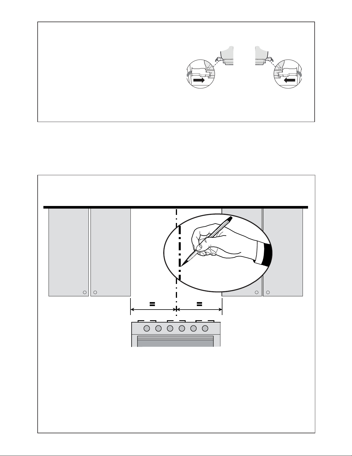
77
8
'LEXMHXQDOtQHDYHUWLFDOHQODSDUHGGHVRSRUWHWDQDOWRFRPRVHDSRVLEOHHQHOFHQWURGHOiUHDGRQGHVHLQVWDODUiODFDPSDQD
'LEXMHXQDOtQHDKRUL]RQWDOHQGRQGHVHXELFDUiHOERUGHLQIHULRUGHODFDPSDQDFRPRVHLQGLFDHQOD¿JXUDTXHHVWiD
XQPtQLPRGHVREUHODVXSHU¿FLHGHFRFFLyQHOpFWULFD\VREUHODGHJDV
A10
A10
Desde el interior de la campana, vuelva a conectar los
conectores en los lados izquierdo y derecho que se
muestran en la imagen de arriba.
7
Instalación con el kit de chimenea opcional - Preparación de la pared
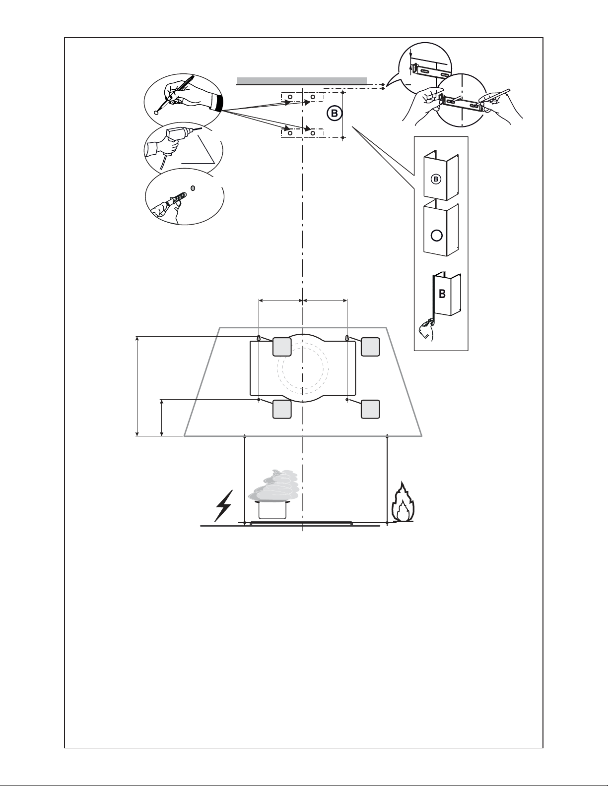
78
Marque la pared donde se indica (A), 11 9/16" por encima de la línea horizontal y a una distancia de 5 1/8" a la izquierda y
derecha de la línea vertical. Comprobando que las dos marcas estén niveladas.
,QVHUWHGRVWDSRQHVGHSDUHG\GRVWRUQLOORVHQORVRUL¿FLRVFRPRVHPXHVWUDQRFRPSOHWDPHQWHVHFRPSUDQSRUVHSDUDGR
Marque la pared donde se indica (B), 4 1/4" por encima de la línea horizontal y a una distancia de 5 1/8" a la izquierda y
derecha de la línea vertical. Comprobando que las dos marcas estén niveladas.
Inserte dos tapones de pared (se compran por separado).
Coloque un soporte 7.2.1 en la pared como se muestra a aproximadamente 1 1/8 " del techo o límite superior, alinee el centro
PXHVFDFRQODOtQHDGHUHIHUHQFLDYHUWLFDO\PDUTXHODSDUHGHQHOFHQWURGHORVDJXMHURVHQHOVRSRUWH
&RORTXHHOVHJXQGRVRSRUWHHQODSDUHGFRPRVHPXHVWUDGHEDMRGHOSULPHUVRSRUWHDODDOWXUDGHODVHFFLyQVXSHULRU
de la chimenea suministrada y alineando el centro (muesca) con la línea vertical.
0DUTXHODSDUHGHQHOFHQWURGHORVDJXMHURVHQHOVRSRUWH\WDODGUHFRQ¡FRPRVHPXHVWUD
/RVWRUQLOORVGHLQVWDODFLyQSURYLVWRVSDUDORVVRSRUWHVGHEHQDVHJXUDUVHFRQWDSRQHVGHSDUHGVHDGTXLHUHQSRUVHSDUDGR
$
´
´
11
9/16”
4
1/4”
5
1/8” 5 1/8”
$
%
$
%
´
>
[
[
´
9

79
10
(QJDQFKH\¿MHHOFXHUSRGHOD
campana en la pared.
Desde adentro, asegure completamente
los 4 tornillos 12a.
L
2x
4
L
4x
11
12
Utilice los cuatro
tornillos (incluidos
con el kit de chi-
PHQHDWHOHVFySLFD
RSFLRQDOSDUD¿MDU
el soporte angular.
13
8
L
4x
M
2x
)LMHHOVRSRUWH
utilizando los
tornillos que se
incluyen en el
kit de chime-
QHDWHOHVFySLFD
opcional.
Instalación con el kit de chimenea opcional
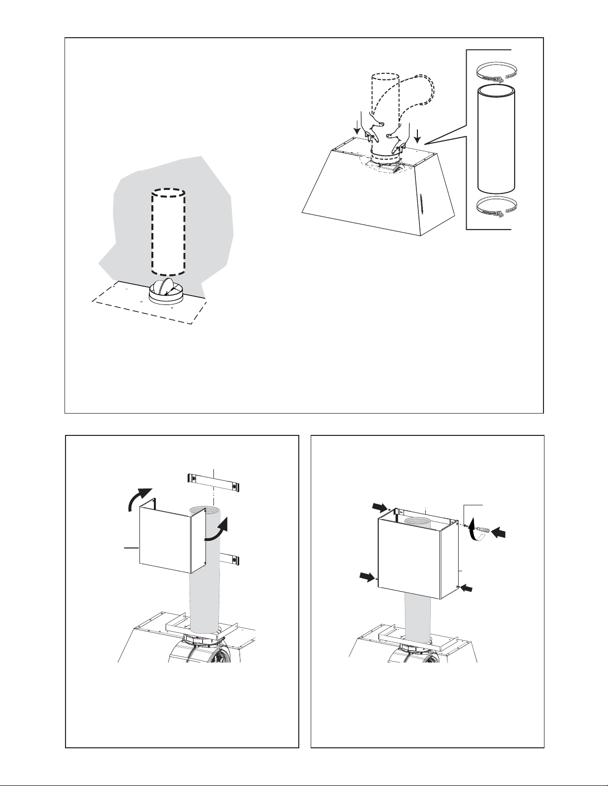
80
Instale el techo o la tapa de pared comprados por separado. Conecte los conductos metálicos de 6 "al
techo o a la tapa de pared y luego conecte los conductos.
N1
10
B
11
N1
M1
4x
B
Ligeramente ensanche los dos lados de la
chimenea superior y engánchelos detrás de
los soportes, asegurándose de que estén bien
asentados.
Asegure los lados a los soportes con los 4 tornillos.
15 16
14

81
Instalación de conexión de cableado
E
A
F
D
C
B
G
Retire la tapa del compartimento de cableado de campo.
NO encienda la unidad hasta que se haya completado la instala-
FLyQ
&RQHFWHHOFDEOHGHODIXHQWHGHDOLPHQWDFLyQDODFDPSDQD
&RQHFWHHOFDEOHGHWLHUUDYHUGHYHUGH\DPDULOORGHEDMRGHOWRUQL-
OORGHFRQH[LyQDWLHUUDYHUGH&RQHFWHHOFDEOHEODQFRGHODIXHQWH
GHDOLPHQWDFLyQDOFDEOHEODQFRGHODFDPSDQDFRQXQFRQHFWRUGH
cable tipo twist-on.
&RQHFWHHOFDEOHQHJURGHODIXHQWHGHDOLPHQWDFLyQDOFDEOHQHJUR
de la campana con un conector de cable tipo twist-on.
Reemplace la cubierta del compartimento de cableado de campo.
17
A. Cable de la fuente de alimentación doméstica
B. Cables negros
C. Conectores de cable con homologación UL
D. Cables blancos
E. Cable de tierra verde (o desnudo) de la fuente de alimentación doméstica conectada al
tornillo de tierra verde
F. Cable de alimentación de la campana
G. Cable de tierra verde del cable de suministro de energía de la campana conectado al
tornillo de tierra verde.
12
N2
N1
N
2x
Agrande ligeramente
los dos lados de la
VHFFLyQLQIHULRU\
enganche entre
ODVHFFLyQVXSHULRU\
la pared, asegu-
rándose de que
estén debidamente
DORMDGRV
B
A
18
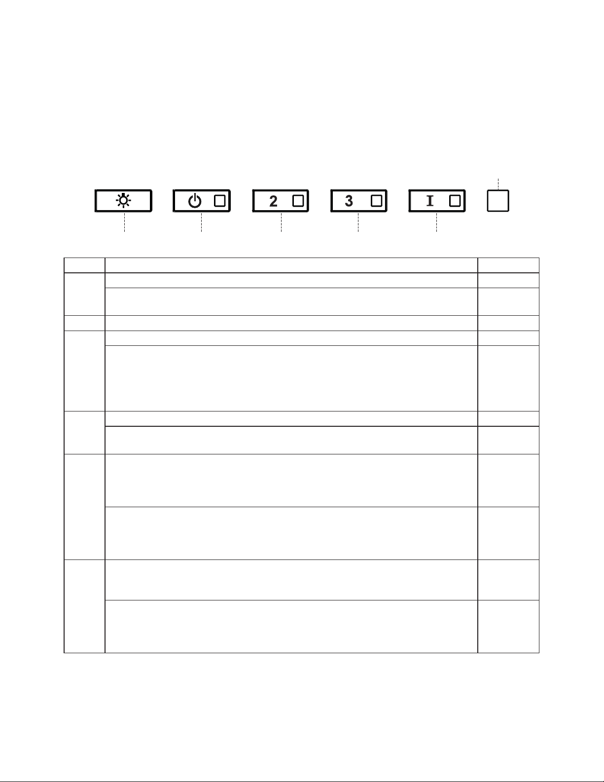
82
INFORMACIÓN DE USO Y CUIDADO
Para mejores resultados
(QFLHQGDODFDPSDQDYDULRVPLQXWRVDQWHVGHFRFLQDUSDUDGHVDUUROODUXQÀXMRGHDLUHDGHFXDGR'HMHTXHOD
FDPSDQDIXQFLRQHGXUDQWHYDULRVPLQXWRVGHVSXpVGHTXHVHFRPSOHWHODFRFFLyQSDUDHOLPLQDUWRGRHOKXPR
y los olores de la cocina.
S1
L T1 T2 T3 T4
Botón Función Led
L Enciende / apaga las luces a máxima potencia. -
0DQWHQJDSUHVLRQDGRHOERWyQGXUDQWHDSUR[LPDGDPHQWHVHJXQGRVSDUDDWHQXDUHOHQFHQGLGR
apagado de las luces.
-
T1 Enciende / apaga el motor a la velocidad uno. -
T2 Enciende el motor a la velocidad dos. -
0DQWHQJDSUHVLRQDGRHOERWyQGXUDQWHDSUR[LPDGDPHQWHVHJXQGRVFRQWRGDVODVFDUJDV
DSDJDGDVPRWRU\OXFHVSDUDDFWLYDUODDODUPDGH¿OWURGHFDUEyQDFWLYDGR(O/('FRUUHVSRQGLHQWH
SDUSDGHDGRVYHFHVSDUDFRQ¿UPDU
3DUDDSDJDUODDODUPDSUHVLRQHHOERWyQQXHYDPHQWH\PDQWpQJDORSUHVLRQDGRGXUDQWHDOPHQRV
5 segundos. El LED correspondiente parpadea una vez.
Destellando
T3 Enciende el motor a la velocidad tres. -
0DQWHQJDSUHVLRQDGRHOERWyQGXUDQWHDSUR[LPDGDPHQWHVHJXQGRVFRQWRGDVODVFDUJDV
apagadas (Motor y luces), para realizar un reinicio. El LED S1 parpadea tres veces.
Destellando
T4 Enciende el motor a velocidad INTENSIVA.
(VWDYHORFLGDGHVWiSURJUDPDGDSDUDIXQFLRQDUGXUDQWHPLQXWRV$O¿QDOGHHVWHWLHPSRHO
sistema regresa automáticamente a la velocidad establecida anteriormente. Si se activa con el
PRWRUDSDJDGRODFDPSDQDFDPELDUiD2))DO¿QDOGHOWLHPSR
-
Presione y sostenga durante 5 segundos para habilitar el mando remoto, indicado por el LED
parpadeando dos veces.
Presione y sostenga durante 5 segundos para deshabilitar el mando remoto, indicado por el LED
parpadeando una vez.
Destellando
S1 6HxDODODDODUPDGHVDWXUDFLyQGHO¿OWURGHJUDVDPHWiOLFRORTXHLQGLFDTXHHVQHFHVDULRODYDU
ORV¿OWURV/DDODUPDVHDFWLYDGHVSXpVGHTXHODFDPSDQDKDHVWDGRHQIXQFLRQDPLHQWRGXUDQWH
KRUDVGHWUDEDMR
)LMDGR
&XDQGRVHDFWLYDVHxDODODDODUPDGHVDWXUDFLyQGHO¿OWURGHFDUEyQDFWLYRORTXHLQGLFDTXH
HO¿OWUR GHEHFDPELDUVH ORV ¿OWURVGH JUDVDPHWiOLFRVWDPELpQ GHEHQODYDUVH/D DODUPDGH
VDWXUDFLyQGHO¿OWURGHFDUEyQDFWLYRHQWUDHQIXQFLRQDPLHQWRGHVSXpVGHTXHODFDPSDQDKD
HVWDGRWUDEDMDQGRGXUDQWHKRUDV
Destellando

83
Unidad De Iluminación Led
• Las luces LED deben ser reemplazadas por el servicio
autorizado por la fábrica Faber.
+HLOHDY@CDKNRkKSQNRCDFQ@R@LDSēKHBNR
(VWRVSXHGHQODYDUVHHQHOODYDYDMLOODV\GHEHQOLPSLDUVHFDGD
vez que se enciende el S1 Led o al menos una vez cada 2
meses de uso, o con mayor frecuencia si el uso es particular-
mente intenso.
Restablecer la señal de alarma
• $SDJDODVOXFHV\HOPRWRUGHDVSLUDFLyQ
• Presione T3 y mantenga presionado durante al menos 3
segundos, hasta que el LED parpadee tres veces como
FRQ¿UPDFLyQ
Limpieza
• 5HWLUHHO¿OWURHPSXMDQGRODSDODQFDKDFLDODSDUWHSRVWHULRU
GHODXQLGDG\DOPLVPRWLHPSRWLUDQGRKDFLDDEDMR
• /DYHHO¿OWURVLQGREODUORGHMHTXHVHVHTXHFRPSOHWDPHQWH
DQWHVGHUHHPSOD]DUORVLODVXSHU¿FLHGHO¿OWURFDPELDGH
color con el tiempo, esto no tendrá ningún efecto sobre su
H¿FLHQFLD
• Reemplace, asegurándose de que el asa esté orientada
hacia adelante.
• /DOLPSLH]DHQHOODYDYDMLOODVSXHGHHVWURSHDUHODFDEDGRGHO
¿OWURGHJUDVDPHWiOLFR
1DDLOK@YNCDKkKSQNCDB@QAŃM@BSHU@CN
Esto no se puede lavar ni regenerar, y debe cambiarse cuando
el LED S1 comience a parpadear, o al menos una vez cada
4 meses. La señal de alarma, si se ha activado, solo aparece
FXDQGRHOPRWRUGHDVSLUDFLyQHVWiHQFHQGLGR
Restablecer la señal de alarma
• $SDJDODVOXFHV\HOPRWRUGHDVSLUDFLyQ
• Presione T3 y mantenga presionado durante al menos 3
segundos, hasta que el LED parpadee tres veces como
FRQ¿UPDFLyQ
Limpieza
• 5HWLUHHO¿OWURGHFDUEyQJLUiQGRORHQHOVHQWLGRGHODVDJXMDV
GHOUHORMKDFLDDWUiVKDVWDTXHVHGHVEORTXHHGHODFDUFDVD
del motor y salga lateralmente.
• 3DUDYROYHUDLQVHUWDUFDGD¿OWURGHFDUEyQFROyTXHORFRQWUD
HOFRVWDGRGHOVRSODGRU\HPS~MHORKDFLDDGHQWUR/XHJR
JLUHHO¿OWURGHFDUEyQHQVHQWLGRKRUDULRKDFLDDGHODQWH
KDVWDTXHHQFDMHHQVXOXJDU
5
Z

84
Diagrama de cableado
+U
'B
+ U
'B

85
January 4, 2016
FABER CONSUMER WARRANTY & SERVICE
All Faber products are warranted against any defect in materials or workmanship for the original purchaser
for a period of 1 year from the date of original purchase (requires proof of purchase). This warranty covers
labor and replacement parts. Faber, at its option, may repair or replace the product or components
necessary to restore the product to good working condition. To obtain warranty service, contact the dealer
from whom you purchased the range hood, or the local Faber distributor. If you cannot identify a local Faber
distributor, contact us at (508) 358-5353 for the name of a distributor in your area.
The following is not covered by Faber's warranty:
1. Service calls to correct the installation of your range hood, to instruct you how to use your range hood, to
replace or repair house fuses or to correct house wiring or plumbing.
2. Service calls to repair or replace range hood light bulbs, fuses or filters. Those consumable parts are
excluded from warranty coverage.
3. Repairs when your range hood is used for other than normal, single-family household use.
4. Damage resulting from accident, alteration, misuse, abuse, fire, flood, acts of God, improper installation,
installation not in accordance with electrical or plumbing codes or Faber documentation, or use of products
not approved by Faber.
5. Replacement parts or repair labor costs for units operated outside the United States or Canada, including
any non-UL or C-UL approved Faber range hoods.
6. Repairs to the hood resulting from unauthorized modifications made to the range hood.
7. Expenses for travel and transportation for product service in remote locations and pickup and delivery
charges. Faber range hoods should be serviced in the home.
THIS WARRANTY DOES NOT ALLOW RECOVERY OF INCIDENTAL OR CONSEQUENTIAL DAMAGES, INCLUDING, WITHOUT
LIMITATION, DIRECT, INDIRECT, INCIDENTAL, SPECIAL OR CONSEQUENTIAL DAMAGES, PERSONAL INJURY/WRONGFUL
DEATH OR LOST PROFITS FABER WARRANTY IS LIMITED TO THE ABOVE CONDITIONS AND TO THE WARRANTY PERIOD
SPECIFIED HEREIN AND IS EXCLUSIVE. EXCEPT AS EXPRESSLY SPECIFIED IN THIS AGREEMENT, FABER DISCLAIMS ALL
EXPRESS OR IMPLIED CONDITIONS, REPRESENTATIONS, AND WARRANTIES INCLUDING, WITHOUT LIMITATION, ANY
IMPLIED WARRANTIES OF MERCHANTABILITY OR FITNESS FOR A PARTICULAR PURPOSE
.
This warranty gives you specific legal rights that may vary from state to state.
Model#: ______________________________ Serial #: _____________________________

86

87

991.0527.958_01 - 180319
D00004610_00