User Binder KBF P 720 Climate Chamber with ICH-compliant
SAFETY
Requirements for the chamber load
- Any solvent must not be explosive and flammable. A mixture of any component of the charging material with air must NOT be explosive. The operating temperature must lie below the flash point or below the sublimation point of the charging material. Any component of the charging material must NOT be able to release toxic gases.
- The loading material shall not contain any corrosive ingredients that may damage the machine components made of stainless steel, aluminum, and copper. Such ingredients include in particular acids and halides. Any corrosive damage caused by such ingredients is excluded from liability by BINDER GmbH.
- The chamber does not dispose of any measures of explosion protection.
Personnel Requirements
- Only trained personnel with knowledge of the Operating Manual can set up and install the chamber, start it up, operate, clean, and take it out of operation. Service and repairs call for further technical requirements (e.g. electrical know-how), as well as knowledge of the service manual.
Installation site requirements
- The chambers are designed for setting up inside a building (indoor use).
- The requirements described in the Operating Manual for installation site and ambient conditions (Chap. must be met.
- Foreseeable Misuse
- Other applications than those described in chap. 1.8 are not approved.
- This expressly includes the following misuses (the list is not exhaustive), which pose risks despite the inherently safe construction and existing technical safety equipment:
- Non-observance of Operating Manual
- Non-observance of information and warnings on the chamber (e.g. control unit messages, safety identifiers, warning signals)
- Installation, startup, operation, maintenance and repair by untrained, insufficiently qualified, or unauthorized personnel
- Missed or delayed maintenance and testing
- Non-observance of traces of wear and tear
- Insertion of materials excluded or not permitted by this Operating Manual.
- Non-compliance with the admissible parameters for processing the respective material.
- Installation, testing, service or repair in the presence of solvents
- Installation of replacement parts and use of accessories and operating resources not specified and authorized by the manufacturer
- Installation, startup, operation, maintenance or repair of the chamber in absence of operating instructions
- Bypassing or changing protective systems, operation of the chamber without the designated protective systems
- Non-observance of messages regarding cleaning and disinfection of the chamber.
- Spilling water or cleaning agent on the chamber, water penetrating into the chamber during operation, cleaning or maintenance.
- Cleaning activity while the chamber is turned on.
Residual Risks
- The unavoidable design features of a chamber, as well as its proper field of application, can also pose risks, even during correct operation. These residual risks include hazards which, despite the inherently safe design, existing technical protective equipment, safety precautions and supplementary protective measures, cannot be ruled out.
- Messages on the chamber and in the Operating Manual warn of residual risks. The consequences of these residual risks and the measures required to prevent them are listed in the Operating Manual. Moreover, the operator must take measures to minimize hazards from unavoidable residual risks. This includes, in particular, issuing operating instructions.
- The following list summarizes the hazards against which this Operating Manual and the Service Manual warn, and specifies protective measures at the appropriate spots:
- Unpacking, Transport, Installation
- Sliding or tilting the chamber
- Setup of the chamber in unauthorized areas
- Installation of a damaged chamber
- Installation of a chamber with damaged power cord
- Inappropriate site of installation
- Missing protective conductor connection
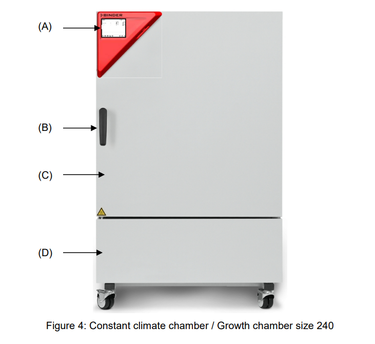
CHAMBER DESCRIPTION AND OVERVIEW
KBWF
- KBWF growth chambers allow simulating the parameters for natural conditions, such as temperature, humidity and light. They can be universally used for conditioning of various types of charging material, even for long-term applications.
- The chambers are equipped with a multifunctional microprocessor color display program controller for temperature, humidity, and illumination control. Temperature is displayed accurate to one-tenth of a degree and humidity to 0.1% r.h.
- With its microprocessor controlled humidifying and dehumidifying system the KBWF is a high-precision growth chamber for programmable light and climate conditions. With its comprehensive program control functions, the MB2 display program controller permits the high precision performance of temperature and humidity cycles and illumination control. Any climatic conditions can exactly be simulated constantly and precisely over long periods of time.
- The chamber is regularly equipped with daylight illumination tubes. It can be optionally equipped with plant growth lamps bearing the ideal spectrum for photosynthesis and thus become the ideal growing chamber for plants under programmable climate conditions.
- Operative ranges are plant biotechnology, agricultural industry, forestry and timber industry, pharmaceutical and chemical industry, basic research, quality assurance and material testing. The fluorescent tubes are built in light cassettes that can be freely positioned within wide areas. They illuminate very homogeneously the racks below them. The lamps can be switched in three groups. By adequately adjusting the program controller, an automatic day/night simulation can be effected.
Humidity control:
- A resistance humidifying system humidifies the air. For this purpose, use deionized demineralized) water. The option BINDER Pure Aqua Service allows using the chamber with any degree of water hardness.
Material:
- The inner chamber, the pre-heating chamber and the interior side of the doors are all made of stainless steel V2A (German material no. 1.4301, US equivalent AISI 304). The housing is RAL 7035 powder-coated. All corners and edges are also completely coated.
- All chamber functions are easy and comfortable to use thanks to their clear arrangement. Major features are easy cleaning of all chamber parts and avoidance of undesired contamination.
Controller:
- The efficient program controller is equipped with a multitude of operating functions, in addition to recorder and alarm functions. Programming of test cycles is easily accomplished via the modern
- MB2 touch screen controller and is also possible directly with a computer via Intranet in connection with the APT-COM™ 4 Multi Management Software (option, chap. 21.1). The chamber comes equipped with an Ethernet serial interface for computer communication. In addition, the BINDER APT-COM™ 4 Multi
- Management Software permits networking up to 100 chambers and connecting them to a PC for controlling and programming, as well as recording and representing temperature and humidity data. For further options, see chap.25.5.
- The chambers are equipped with four castors. Both front castors can be easily locked via the attached brakes.
Temperature range:
- 0 °C / 32 °F up to 70 °C / 158 °F without light cassettes, 10 °C / 50 °F up to 60 °C /
F with illumination
- KBF LQC / KBF LQC-UL: When at least one light sensor is plugged-in, the maximum temperature is automatically limited to 60 °C.
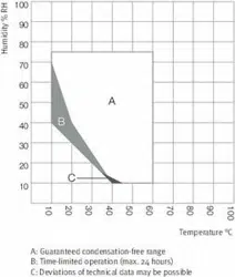
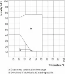
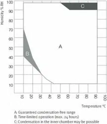
- Humidity range: 10% r.h. to 80% r.h.
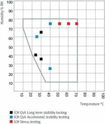
- For the control ranges of temperature and humidity, see climatic diagrams (chap. 18
COMPLETENESS OF DELIVERY, TRANSPORTATION, STORAGE, AND
INSTALLATION
- Note on second-hand chambers (Ex-Demo-Units):
- Second-hand chambers are chambers that were used for a short time for tests or exhibitions. They are thoroughly tested before resale. BINDER ensures that the chamber is technically sound and will work flawlessly.
- Second-hand chambers are marked with a sticker on the chamber door. Please remove the sticker before commissioning the chamber.
- Guidelines for safe lifting and transportation
- The front castors can be blocked by brakes. After operation, please observe the guidelines for temporarily decommissioning the chamber (chap. 24.2). Please move the chambers with castors only when empty and on an even surface, otherwise the castors may be damaged.
Storage
- Intermediate storage of the chamber is possible in a closed and dry room. Observe the guidelines for temporary decommissioning (chap. 24.2).
- Permissible ambient temperature range during storage:
- If the steam humidifying system has NOT been emptied: +3 °C / 37.4 °F to +60 °C / 140 °F.
- After BINDER Service has emptied the steam humidifying system: -10 °C / 14 °F to +60 °C / 140 °F
- With temperatures below +3 °C / 37.4 °F, water must be completely removed from the humidifying system.
INSTALLATION AND CONNECTIONS
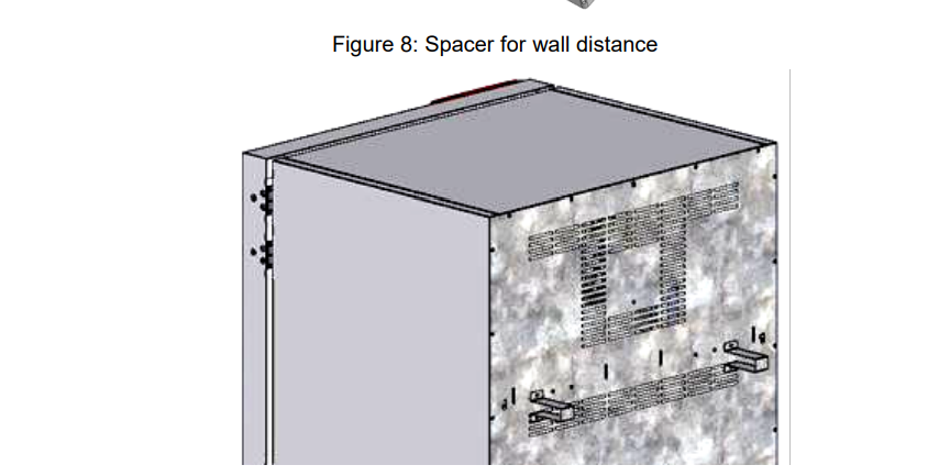
- Spacer for wall distance Please fix both spacers with the supplied screws at the chamber rear. This serves to ensure the prescribed minimum distance to the rear wall of 100 mm / 3.94 in.
Wastewater connection Fasten the wastewater hose to the wastewater connection “OUT” (14) on the rear of the chamber (olive ∅ 14 mm). Observe the following points:
• You can use a part of the supplied water hose as a drainage hose. In case another hose is used, it has to be permanently resistant against at least 95 °C / 203 °F.
• Mount the wastewater hose with a maximum positive inclination of 1 m and a maximum total length of 3 m.
• Protect the chamber end of the drainage hose with one of the supplied hose clamps. • Reliably prevent sucking back of wastewater. The end of the wastewater hose must not be immersed in liquids. This can be ensured e.g., by free discharge.
Automatic fresh water supply via water pipe
- An enclosure inside the chamber contains the connection kit for freshwater and wastewater. Install the freshwater connection using either the enclosed water hose or another pressure-resistant one. To accomplish this, remove the cover of the freshwater connection
- “IN” (13) on the rear of the chamber. Protect both ends of the hose with two of the four supplied hose clamps. Before turning on the chamber, check the connection for leaks. Water supply is automatically effected via the freshwater connection “IN” (13).
- Connection kit for connecting the chamber to the water main
- A safety kit against flooding caused by burst water hoses is enclosed with the constant climate chamber.
It consists of the following:
- Hose burst protection device hose nozzles with screwing hose clamps m water hose, divisible for the feed hose and drain
- Protection principle of hose burst protection:
- Whenever a strong water flow of about 18 l / min. occurs, e.g. caused by a burst water hose, a valve automatically cuts off the water supply, which can be heard as a clicking noise. The water supply now remains shut until it is manually released.
Assembly:
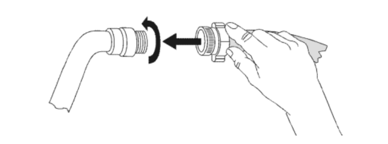
- Screw the hose burst protection device onto a water tap with a G¾ inch right turning thread connection.
- The connection is self-sealing. Establish the connection between the safety kit and the chamber with a part of the supplied hose. Protect both ends of the hose by the supplied hose clamps.
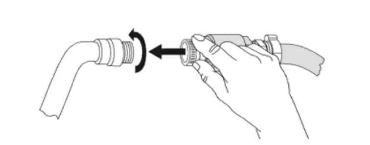
- We recommend connecting the hose as the last step in order to avoid twisting the hose while screwing on the safety kit.
- Open the water tap slowly in order to avoid actuating the hose burst protection device.
Release of the reflux protection device:
- In case the hose burst protection device interrupts the water supply, first find the reason and remove it as necessary.
- Close the water tap. Release the valve by a half left-turn of the upper knurled part. You can hear the release of the valve as a clicking noise. Tighten the burst protection device against the water tap by a right turn. Open the water tap slowly afterwards.
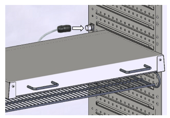
- Installation and connection of the light cassettes You can insert the light cassettes in different heights onto the beads at the lateral walls of the chamber.
- Insert and pull out the light cassettes only by the handles. Connect the cables of the light cassettes to its closest connection socket at the right side in the back of the chamber. Put the waterproof plug on the connection socket. When the plug has engaged, turn the locking-nut of the plug several times to the right up to its final stopping point. The plug is now automatically sealed into the socket.
FUNCTIONAL OVERVIEW OF THE MB CHAMBER CONTROLLER
- The MB2 chamber controller controls following parameters inside the chamber:
- Temperature in °C
- Relative humidity in % r.h.
- Fan speed in %
Illumination
- KBF LQC / KBF LQC-UL: In addition to displaying the actual values of UVA and the visible spectral range, the function “Light Quantum Control” permits cumulative measurement of the light doses. In Manual Mode you can enter target dose values of UVA and the visible spectral range. When they are reached, the UVA, and cool white fluorescent tubes automatically turn off independently from each other.
- For the control ranges of temperature and humidity, see climatic diagrams (chap. 18).
- You can enter the desired set point values in fixed value operation mode directly on the display surface or via the setpoint menu. For program operation the controller offers programming week and time programs.
- In addition there is a timer program available (stopwatch function).
- The controller offers various notifications and alarm messages with visual and audible indication and remote alarms via e-mail, an event list (trace file) and the graphical display of the measuring values in the chart recorder view.
- The MB2 program controller permits programming temperature and humidity cycles, and specifying illumination, fan speed and special controller functions for each program section. You can enter values or programs directly at the controller or use the APT-COM™ 4 Multi Management Software option) specially developed by BINDER.
Idle mode
- The controller is not functional, i.e., there is no heating or refrigeration and no humidification or dehumidification. The fan is off. The chamber approximates ambient values.
The fluorescent tubes are off.
- You can activate and deactivate this operating mode with the “Idle mode” control contact in Fixed value operating mode (chap. 8.4), time program operation (chap. 10.7.3) and week program operation chap. 11.6.5).
Fixed value operating mode
- The controller operates as a fixed-point controller, i.e., set-points for temperature, humidity, and fan speed can be defined, which are then maintained until the next manual change (chap. 8.1).
Timer program operation
- Stopwatch function: during an entered duration the controller constantly equilibrates to the setpoints entered in Fixed value operation mode.
Time program operation
- An entered time program for temperature and humidity is running. The controller offers 25 program memory places with 100 program sections each. The total number of program sections of all programs is unlimited
Week program operation
- An entered week program for temperature and humidity is running. The controller offers 5 program memory places with 100 switching points each. The switching points can be distributed over all days of the week.
START UP
Turning on the chamber
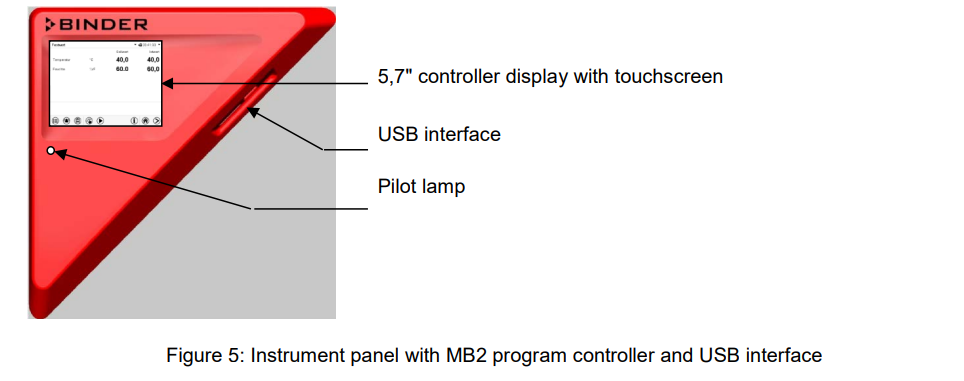
- After connecting the supply lines (chap. 4), turn on the chamber by its main power switch (1). The lit pilot lamp shows the chamber is ready for operation.
- When the main power switch is turned on and yet the controller display is dark, the display is in standby mode. Press on the touchscreen to activate it.
- Open the water-tap for freshwater supply. Alternatively, fill the freshwater can (option, chap. 21.9).
- The humidifying and dehumidifying system must be activated (deactivated operation line “Humidity off”, chap. 8.4 and setting “Control on”, chap. 6.3).
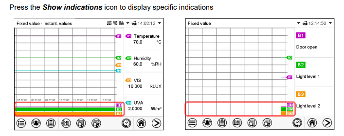
- KBF LQC / KBF LQC-UL: When operation line “LQC” is activated, light integration takes place: In fixed value and program operation mode, the fluorescent tubes automatically turn on until they reach the selected target dose values of UVA and the visible spectral range. If the operation line “Idle mode” is activated, the fluorescent tubes are off. In the chart recorder display, the actual values are displayed under “Instantaneous values” and the integrated light values under “Dose values”.
- After the first turning on of the chamber or after an interruption of the power supply the relative humidity will increase after a delay of about 20 minutes. During this period, the relative humidity can drop considerably.
- Warming chambers may release odors in the first few days after commissioning. This is not a quality defect. To reduce odors quickly we recommend heating up the chamber to its nominal temperature for one day and in a well-ventilated location.
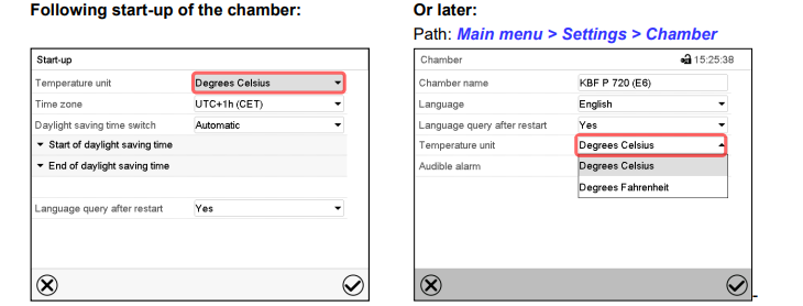
- Controller settings upon start up The window „Language selection“ enables the language selection, in case that it’s activated in the “Start-up” menu. Afterwards occurs a request of the time zone and the temperature unit.
- The controller will function in the operating mode, which was active before the last shut-down. It controls temperature and humidity in fixed value operating mode to the last entered values and in the program mode to the set points achieved beforehand.
Locked operation
- Provided that the user administration has been activated by the assignment of passwords for the different authorization types, the controller operation is first locked after turning on the unit, recognizable by the closed lock icon in the header.
- In the locked view the controller provides all display functions. No setting functions are available.
- The setpoints are shaded (light grey) in normal display. Changing them by direct entry in the fixed value operating mode is not possible. The functional icons for setpoint entry and program start in the footer are without function.
- After turning on the unit, user log-in is required to operate the controller (chap. 14.2)
- Operation without user log-in / without password-protection
- If the password function has been deactivated, after turning on the unit without user log-in there are those controller functions available, which correspond to the highest authorization level without a password protection. There is no lock icon in the header.
FUNCTION OF LIGHT MEASUREMENT, AND INTEGRATION: LIGHT
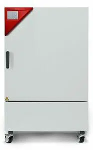
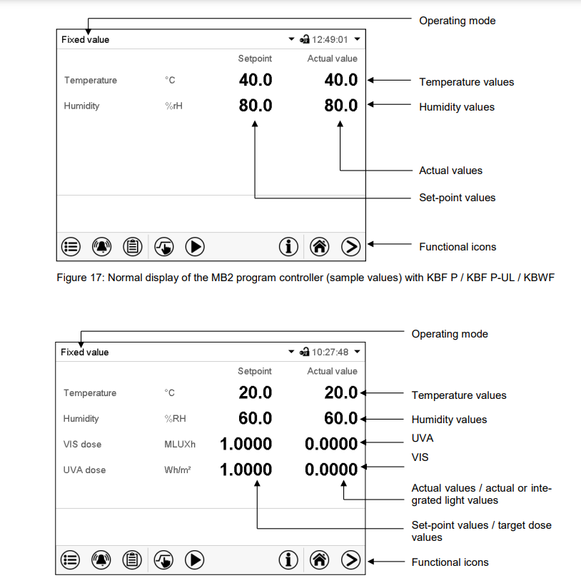
- Display of the instantaneous and the integrated values
- The instantaneous values and the dose values of VIS and UVA are constantly measured. The dose values (set-point and actual values) are always shown in Normal Display independent on the controller operation mode. Additionally in the chart recorder display the instantaneous values (actual values) are shown under “Instantaneous values” and the integrated light values (set-point and actual values) under “Dose values”, see chap. 17.
- Integrative function: Operation line “LQC On” not activated
- The LQC symbol in the screen header indicates that the integrative function has been activated via operation line “LQC On”.
KBF P / KBF P-UL + KBF LQC / KBF LQC-UL + KBWF (E6) 08/2020 page 55/183
- Integration takes place as soon as operation line “LQC On” is activated, and at least one target dose value other than 0.0 has been entered. With target dose value 0.0, or in case the entered target dose value has been reached, the fluorescent tubes do not turn on automatically. The illumination can be turned on and off with the operation lines “Light VIS” and “Light UVA”.
- Every minute the integrated values of UVA and VIS increase by the respective instantaneous value.
- The displayed units are Wh/m2 and MLUXh. The maximum value of the integrated value display is the respective value reached with the last addition before exceeding 99999. The integration display on the controller display will then not increase any longer. Recording by the APT-COM™ 4 Multi Management Software (option, chap. 21.1) can continue correctly until overflow of the numeral format Floating
Point.
- In fixed value and program operation mode the illumination equipment automatically turns on when entering a dose target value higher than a dose value already reached. Additionally activating operation lines “Light VIS” and “Light UVA” can prevent the automatic turning-off when the target dose value has been reached.
- If operation line “Idle mode” is activated, the integrative function is not active. The illumination is off.
- Integration continues until operation line “LQC On” is deactivated. The integrated values reached so far continually remain stored but are not displayed. Integration can be continued any time.
Resetting the integrated values
- Operation lines “LQC Reset VIS” and “LQC Reset UVA” serve to reset to zero the integrated values of UVA and VIS once in a time.
- To do this, the corresponding operation line must be activated for at least 5 seconds (consider when programming!). The reset is effective once, i.e. for a repeated reset, first deactivate the operation line (clear the checkbox and confirm) and then activate it again.
Operation line “LQC On” not activated
- There is no integration. Previously reached integrated values, if any, remain stored but are not displayed.
- You can turn on the fluorescent tubes with the operation lines “Light VIS” and “Light UVA”.
- The symbols “VIS” and “UVA” in the screen header indicate that the corresponding fluorescent tubes have been activated with the operation lines “Light VIS” and “Light UVA”.
SET-POINT ENTRY IN “FIXED VALUE” OPERATING MODE
- Automatic correction of the actual value when turning on or off the illumination
- The chambers have been adjusted for operation with maximum illumination. Since the illumination creates a heat input in the chamber, this is considered automatically when operating without illuminatio
- This can be recognized when turning on or off the illumination by a change of the actual temperature and humidity values, which subsequently will equilibrate again to the set-points.
TIMER PROGRAM: STOPWATCH FUNCTION
Timer program:
- stopwatch function During an entered duration the controller constantly equilibrates to the setpoints entered in Fixed value operation mode (temperature, humidity, fan speed, configuration of the operation lines). This duration can be entered as a “Timer program”.
- During the program runtime, any setpoint changes do not become effective; the controller equilibrates to the values which were active during program start.
Performance during program delay time
- During the configured program delay time until program start, the controller equilibrates to the current setpoints of Fixed value operation mode. Modifications of these setpoints are possible but become effective only after the timer program is finished
- When the configured moment for program start is reached, the program delay time ends and the program starts running. The controller equilibrates to the values which had been active during program start
TIME PROGRAMS
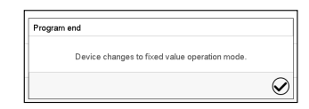
After the end of the program the message
- “Device changes to fixed value operation mode” appears on the screen. Press the Confirm icon. After confirming the message the controller changes to Fixed value operation mode. Temperature and humidity will then equilibrate to the setpoints of Fixed value operation mod
Starting an existing time program
In Normal display press the Program start icon to access the “Program start” menu.
“Program start” menu
• In the field “Program type” select the setting “Time program”.
• In the field “Program” select the desired program.
• Select the field “Program start” and enter the desired program start time in the “Program start” entry
menu.
- Press the Confirm icon. The program delay time until program start begins.
- The program end is adapted automatically depending on the entered program duration.
- After completing the settings, press the Confirm icon to take over the entries and exit the menu. The
- program starts running.
- If instead you press the Close icon to exit the menu without taking over the entries, the program will not
start.
Performance during program delay time During the configured program delay time until program start, the controller equilibrates to the current setpoints of Fixed value operation mode. Modifications of these setpoints are effective. When the configured moment for program start is reached, the program delay time ends and the program starts running.
WEEK PROGRAMS
Tolerance ranges
- For temperature and humidity and, with KBF LQC / KBF LQC-UL, for the VIS and UVA dose, you can specify a tolerance range for each program section with different values for the tolerance minimum and maximum. When the actual value exceeds the given threshold, the program is interrupted.
- This is indicated on the display (see below). When the actual temperature is situated again within the entered tolerance limits, the program automatically continues. Therefore, the duration of the program may be extended due to the programming of tolerances.
Repeating one or several sections within a time program
- You can repeat several subsequent sections together. It is not possible to define the start section the same time also as the target section, therefore you cannot repeat a single individual section. Enter the desired number of repetitions in the field
- Number of repetitions“ and the number of the section to start the repetition cycle with in the field “Start section for repetition” To have sections repeated infinitely, enter the number of repetitions as “-1”. The selected sections are repeated as many times as selected. Then the program continues
TEMPERATURE SAFETY DEVICES
Over temperature protective device (class
- The chamber is equipped with an internal temperature safety device, class 1 acc. to DIN 12880:2007. It serves to protect the chamber and prevents dangerous conditions caused by major defects
- If a temperature of approx. 110 °C / 230 °F is reached, the over temperature protective device permanently turns off the chamber. The user cannot restart the device again.
- The protective cut-off device is located internally. Only a service specialist can replace it. Therefore, please contact an authorized service provider or BINDER Service.
Overtemperature safety controller class 3.
- The chambers are regularly equipped with an electronic overtemperature safety controller (temperature safety device class 3.1 according to DIN 12880:2007).
- The safety controller is functionally and electrically independent of the temperature control system. If an error occurs, it performs a regulatory function. With option temperature safety device class 3.3 (chap. 13.3), the safety controller is not used. It must be set to the maximum limit value (70 °C / 158 °F).
- Please observe the DGUV guidelines 213-850 on safe working in laboratories, issued by the employers’ liability insurance association (for Germany).
- The overtemperature safety controller serves to protect the chamber, its environment and the contents from exceeding the maximum permissible temperature. In the case of an error, it limits the temperature inside the chamber to the entered safety controller set-point.
- This condition (state of alarm) is indicated visually and additionally with an audible alert if the buzzer is enabled (chap. 12.5). The alarm persists until the chamber cools down below the configured safety controller setpoint.
USER MANAGEMENT
“Master” authorization level
• Highest authorization level, only for developers
• Extensive authorization for controller operation and configuration, outputs/inputs, alarm settings, parameter sets and operating ring display
• All passwords can be changed in the “log out” submenu (chap. 14.3).
“Service” authorization level
• Authorization level only for BINDER service
• Extensive authorization for controller operation and configuration, access to service data
• The passwords for “Service”, “Admin” and “User” authorization levels can be changed in the “log out” submenu (chap. 14.3).
“Admin” authorization level
• Expert authorization level, for the administrator
• Authorization for controller configuration and network settings and for operating those controller functions required for operating the chamber. Restricted access to service data.
• Password (factory setting): “2”.
• The passwords for “Admin” and “User” authorization levels can be changed in the “log out” submenu (chap. 14.3).
“User” authorization level
• Standard authorization level for the chamber operator
• Authorization for operating the controller functions required for operating the chamber.
• No authorization for controller configuration and network settings. The “Settings” and “Service” submenus of the main menu are not available.
• Password (factory setting): “1”
• The password for the “User” authorization level can be changed in the “log out” submenu (chap. 14.3).
As soon as a password has been assigned for an authorization level, the access to this level and the related controller functions are only available after log-in with the appropriate password
If for an authorization level no password is assigned, the related controller functions of this level are available for every user without login. If passwords have been assigned for all authorization levels, access to the controller functions is locked without login.
Operation after user login
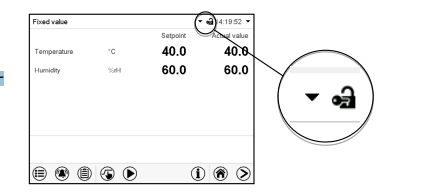
- At user login, the authorization level is selected and confirmed by entering the respective password. Following user login, controller operation is available, recognizable by the open-lock icon in the header.
- The available controller functions correspond to the user’s authorization level.
- Password protection activated for all levels: operation without user login is locked If passwords have been assigned for all authorization levels, the controller is locked without registration of a user.
- As long as no user is registered, controller operation is locked, recognizable at the closed-lock icon in the header. This requires that the user management has been activated by the assignment of passwords for the individual authorization levels.
GENERAL CONTROLLER SETTINGS
Selecting the temperature unit
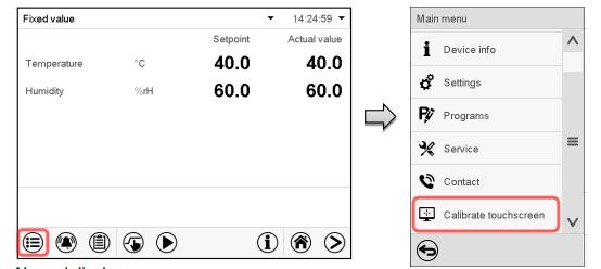
Touchscreen calibration
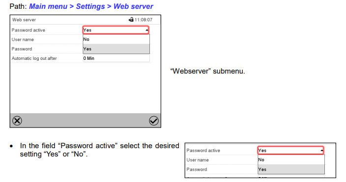
Web server
- Event list The “Event list” displays status information and errors of the current day. It enables to view the last 100 events or defective conditions of the chamber.
- Self-test function The self-test function enables an automated check of the proper chamber functioning as well as a targeted and reliable fault analysis.
- It is available with the “Master”, “Service”, and “Admin” authorization levels. In this case, the chamber successively undergoes various defined operating states, which serves to determine reproducible characteristic values. These characteristic values provide information on the performance and precision of the individual functional systems of the chamber (e.g., heating, refrigeration, humidification) of the chamber.
- The results of the self-test are stored in the service recorder of the controller. You can export them using the controller’s USB interface and send them to BINDER Service (use function “Export service data” to USB stick, chap. 15.6). BINDER Service will evaluate the data using an analyzing tool.
CHART RECORDER DISPLAY
Show and hide specific indications
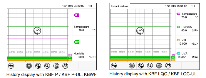
History display
HUMIDIFICATION / DEHUMIDIFICATION SYSTEM
Humidification / dehumidification system
- The chamber is equipped with a capacitive humidity sensor. This results in a control accuracy of up to +/- 3 % r.h. of the set point.
- The temperature-humidity diagrams show the possible working ranges for humidity. • In the “setpoints” menu you can turn humidity control (humidification and dehumidification) on or off with the setting “Control on/off” (chap. 6.3).
- With humidity control turned off, the humidification module cools down. After activation it will take up to 20 minutes until the humidification function is fully available again. This setting is required when operating the chamber without a water connection in order to avoid humidity alarms.
- Operation line “Humidity off” serves to turn off the humidification / dehumidification system in Fixed value operation (chap. 8.4, time program operation (chap. 10.7.3) and week program operation (chap. 11.6.5).
- This allows configuring the disconnection for individual program sections. When the humidification / dehumidification system is turned off via operation line it remain on standby (filled and heated). Therefore it is immediately available after turning on.
Humidifying system
- The humidifying and dehumidifying system is located in the humidity generation module. In a cylindrical container with a volume of about 2 liters an electrical resistance heating evaporates water.
- The water content is kept exactly at the boiling point, and thus steam can be immediately generated in sufficient quantity for rapid humidity increases or for compensation of humidity losses, e.g. by door openings.
- Condensation forming on the outer walls of the useable volume is led through a water drain in the outer chamber into the wastewater can which is pumped off automatically to the wastewater pipe when required.
DEFROSTING AT REFRIGERATING OPERATION
- BINDER constant climate chambers are very diffusion-proof. To ensure high temperature precision there is no automatic cyclic defrosting device.
- The DCT™ refrigerating system largely avoids icing of the evaporation plates. However, at very low temperatures the moisture in the air can condense on the evaporator plates leading to icing.
CLEANING AND DECONTAMINATION
- Standard commercial cleaning detergents free from acid or halides. Alcohol-based solutions. We recommend using the neutral cleaning agent Art. No. 1002-0016.
- Instrument panel Standard commercial cleaning detergents free from acid or halides. We recommend using the neutral cleaning agent Art. No. 1002-0016. KBF LQC / KBF LQC-UL: Light sensors Wipe with a soft, if desired moistened towel.
- Do not mechanically strain the light sensors during cleaning and take care not to scratch them. Zinc coated hinge parts rear chamber wall Standard commercial cleaning detergents free from acid or halides. Do NOT use a neutral cleaning agent on zinc coated surfaces.
MAINTENANCE AND SERVICE, TROUBLESHOOTING, REPAIR, TESTING.
Simple troubleshooting
- Chap. 23.5 describes troubleshooting by operating personnel. It does not require technical intervention into the chamber, nor disassembly of chamber parts.
- For personnel requirements please refer to chap. 1.1.
Detailed troubleshooting
- If errors cannot be identified with simple troubleshooting, further troubleshooting must be performed by
- BINDER Service or by BINDER qualified service partners or technicians, in accordance with the description in the Service Manual.
- For personnel requirements please refer to the Service Manual.
Repair
- Repair of the chamber can be performed by BINDER Service or by BINDER qualified service partners or technicians, in accordance with the description in the Service Manual.
- After maintenance, the chamber must be tested prior to resuming operation.
Electrical testing
- To prevent the risk of electrical shock from the electrical equipment of the chamber, an annual repeat inspection as well as a test prior to initial startup and prior to resuming operation after maintenance or repair, are required.
- This test must meet the requirements of the competent public authorities. We recommend testing under DIN VDE 0701-0702:2008 in accordance with the details in the Service Manual.
DISPOSAL
- Electrical and electronic equipment (WEEE), BINDER devices are classified as “monitoring and control instruments” (category 9) only intended for professional use“. They must not be disposed of at public collecting points.
- The chambers bear the symbol for the marking of electrical and electronic equipment manufactured / placed on the market in the EU after 13 August 2005 and be disposed of in separate collection according to Directive 2012/19/EU on waste electrical and electronic equipment (WEEE) and German national law for electrical and electronic equipment (Elektro- und Elektronikgerätegesetz, ElektroG). WEEE marking: crossed-out wheeled bin with solid bar under.
- A significant part of the materials must be recycled in order to protect the environment. At the end of the device’s service life, have the chamber disposed of according to the German national law for electrical and electronic equipment (Elektro- und Elektronikgerätegesetz, ElektroG from 20 October 2015, BGBl. I p. 1739) or contact BINDER service who will organize taking back and disposal of the chamber according to the German national law for electrical and electr
TECHNICAL DESCRIPTION
- According to Annex I of Directive 2012/19/EU of the European Parliament and of the Council on waste electrical and electronic equipment (WEEE), BINDER devices are classified as “monitoring and control instruments” (category 9) only intended for professional use“. They must not be disposed of at public collecting points.
- The chambers bear the symbol for the marking of electrical and electronic equipment manufactured / placed on the market in the EC after 13 August 2005 and be disposed of in separate collection according to the Directive 2012/19/EU on waste electrical and electronic equipment (WEEE). WEEE marking: crossed-out wheeled bin with solid bar under.
- At the end of the device’s service life, notify the distributor who sold you the device, who will take back and dispose of the chamber according to the Directive 2012/19/EU on waste electrical and electronic equipment (WEEE)