Loading ...
Loading ...
Loading ...
ASSEMBLY INSTRUCTIONS
7
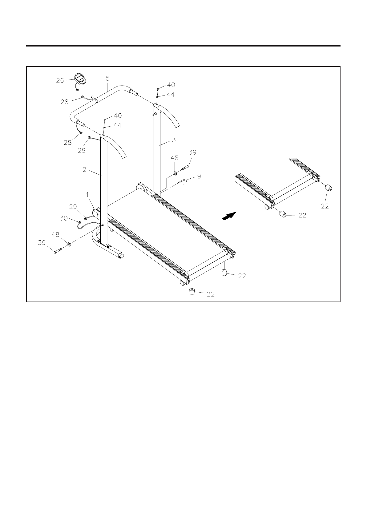
STEP 3: Place the BASE FRAME(1) between the LEFT and RIGHT UPRIGHTS(2, 3) and secure
with
HEX BOLTS(M12 x 70mm)(39) and WASHERS(M12)(48). DO NOT TIGHTEN COMPLETELY.
STEP 4: Secure the U-SHAPED HANDRAIL(5) onto the LEFT and RIGHT UPRIGHTS(2, 3) with
BUTTON HEAD BOLTS(6mm x 15mm)(40) and ARC WASHERS(M6)(44). Connect the UPPER
EXTENSION WIRE(28) to the LOWER EXTENSION WIRE(29).
STEP 5: Go back and tighten HEX BOLTS(M12 x 70mm)(39) in STEP 2. Connect the LOWER
EXTENSION WIRE(29) located on the LEFT UPRIGHT(2) to the SENSOR WIRE(30). Insert the
PULL PIN(9) through the RIGHT UPRIGHT(3) and BASE FRAME(1) to lock the BASE FRAME(1) in
position.
STEP 6: Install two "AA" batteries into the METER(26), two batteries included. See page 8 for detailed
battery installation instructions. Slide the
METER(26) onto the plate on the U-SHAPED HANDRAIL(5).
Connect the UPPER EXTENSION WIRE(28) to the METER(26).
STEP 7: Attach the BUMPER STANDS(22) to the bottom of the BASE FRAME(1).
NOTE: The BUMPER STANDS(22) may be stored on the end of the BASE FRAME(1) to increase the
angle of the treadmill and reduce the walking resistance. See page 10 for details on adjusting the walking
resistance.
Loading ...
Loading ...
Loading ...