Loading ...
Loading ...
Loading ...
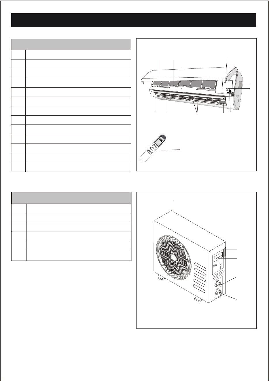
NAMES OF PARTS
No.
Description
1
2
Front panel
Air filter
Optional filter (if installed)
3
Terminal block cover
4
Emergency button
5
6
LED Display
Signal receiver
7
Airflow direction louver
8
Deflectors
9
Remote controller
10
Note: The above figures are only intended to be a
simple diagram of the appliance and may not
correspond to the appearance of the units that
have been purchased.
No.
Description
13
Air outlet grill
Terminal block cover
14
Gas valve
15
Liquid valve
16
11
Indoor unit rating label ( )Stick position optional
17
Outdoor unit rating label
12
Ionizer (Not equipped on this model) generator
13
15
16
17
INDOOR UNIT
5
OUTDOOR UNIT
1
2-3
6
4-5
9
11
8
10
7
14
12
10
Note: The deflectors are positioned mannually and placed under the flap.They are allowed to direct the airflow
rightward and leftward mannually.
Loading ...
Loading ...
Loading ...